snow caster operator's manual 9-50863 snow... · this manual also pertains to the k·so and...
TRANSCRIPT

I
-
SNOW CASTER
L-80 AN D L-84
Operator's Manual 9-50863
...
"
J I Case A Tenneco Company
.. ,.

A This Safety Alert Symbol Indicates Important .~
Safety Messages In This Manual When You See This Symbol Carefully Read The Message That Follows and Be Alert To The Possibility , Of Personal Injury Or Death
IF THIS MACHINE IS USED BY AN EMPLOYEE OR IS LOANED OR RENTED, MAKE ABSOLUTELY CERTAIN THAT THE OPERATOR(S), PRIOR TO OPERATING:
1. IS INSTRUCTED IN SAFE AND PROPER USE.
2. REVIEWS AND UNDERSTANDS THE MANUAL(S) PERTAINING TO THE MACHINE.
751253
~
BEFORE STARTING ENGINE STUDY OPERATOR'S MANUAL SAFETY MESSAGES
READ ALL SAFETY SIGNS ON MACHINE CLEAR THE AREA OF OTHER PERSONS
LEARN & PRACTICE SAFE USE OF CONTROLS BEFORE OPERATING
IT IS YOUR RESPONSIBILITY TO UNDERSTAND AND FOLLOW MANUFACTURER'S INSTRUCTIONS ON MACHINE OPERATION, SERVICE. AND TO OBSERVE PERTINENT LAWS AND REGULATIONS. OPERATOR AND SERVICE MANUALS MAY BE OBTAINED FROM YOUR EQUIPMENT DEALER.
.~
2

SAFETY MESSAGES
A IMPORTANT: The safety messages contained in this manual are to be used together with the Safety Messages appearing in the tractor operator's manual. Be sure to review both carefully before operating the tractor snow caster combination_
A CAUTION: Keep the area of operation clear of all persons particularly small children.
h CAUTION: Give complete and un· ~ divided attention to the job at hand.
3

;--.
A WARNING: Contact by any part of the body with the rotating snow caster auger can result in serious injury.
Extra care should be used around exposed areas such as the auger and discharge chute.
ALWAYS: 1. Disengage the attachment drive clutch,
2. shut off tr actor engine,
3. set parking brake, and
4. wait for all motion to stop.
BEFORE approaching or allowing anyone else to approach the front of the tractor to: 1. clear the auger or
discharge chute, 2 . change position of
chute deflector, 3. service or adjust snow
caster or tractor, or 4. for any other reason
h CAUTION: Nevel di,cct snow ~ discharge at people or buridilHjS.
h ~
A
A IMPORTANT:
CAUTION : Di s(, ngcf(j(' attachmellt d"ve clutch when tlallsportllHj.
CAUTION: Disengage the attachment d rive clutch when stal ti ng engine dnd whell transporting the snovv caster. Before the first snowfall, the area in which snow removal IS to take place should be cleared of all stones, ~ticks, pte., which might be picked LIP by the snow caster. OBSTACLES SUCH AS DRIVEWAY MARKERS, WATER OR GAS SHUT OFFS, ETC. SHOULD BE MARKED SO THEIR LOCATIONS UNDER THE SNOVV ARE' VE RY OBVIOUS .
CAUTION: Do not allow anyone other than the operator to ride on ..--.... the tractor or to be towed behind_
Always install new decals whenever ,the old decals are destroyed, lost, painted over or illegible. When individual parts are replaced that have decals attached, be sure to install a new decal with the new part. Replacement decals are available from your Case Dealer.
..........
.... 4

INTRODUCTION
The Model LSO, 3S" Snow Caster is designed for use on Case model 210, 220 and 222 Compact Tractors above serial number 9646S00. The Model LS4, 4S" Snow Caster is furnished complete to mount on all Model 222, 224, 444 and 446 Compact Tractors above serial number 9646S00.
This manual also pertains to the K·SO and K-S4 Snow Caster.
This manual covers recommended operating procedures, safety suggestions, maintenance information, adjustments and installation instructions. Read this manual carefully
before operating your snow caster. Your J I Case Compact Tractor Dealer is well qualified to answer any further questions you might have concerning your snow caster. Also, if the need should arise, his Service Department with factory trained technicians, genuine Case replacement parts and the required facilities is in a position to provide repairs in the shortest time possible.
The definitions "Right, Left, Front and Rear" as used throughout this manual relate to the tractor and snow caster when the operator is. seated facing forward in the normal operating pOSition on the tractor.
OPERATING CONTROLS
The principle components and controls of the tractor and The chute crank, attachment drive clutch and lift lever snow caster are identified in Figure 1 with the same controls are all conveniently located near the operator's description used throughout the manual. Refer to the position on the tractor. The auger is placed in motion by tractor Operator's Manual for identification of all tractor engaging the tractor attachment drive clutch. The chute controls. crank adjusts the direction of snow discharge and the
deflector angle controls the distance the snow is blown .
CHUTE CRANK
DEFLECTOR
SKID SHOE
FIGURE 1
Model 444 Tractor with L·84 Snow Caster, K-l0 Wheel Weights, and E· 16 Tire Chains
5

--TIRE CHAINS AND WHEEL WEIGHTS
The use of tire chains and wheel weights, or rear weight CAUTION: Extreme cdutlon should box is recommended for snow removal operation. The be exercised L1ndel slippery CUIHII extra traction resulting gives the tractor operator maneuv tlons. Reduce fUIWJI d speed. 111,1.111 erability in handling heavy snow removal jobs. These tilt! chains dnt! wlwel \V!'lqhh toAaccessories are sold by your dealer and are not included traction wheels fOI added saft~ly with the snow caster.
OPERATING TIPS
WARNING: Contact by any part
CAUTION: Nevel dlltxt SIlUW of the body With the rotating snow
~ dlschal'qe at people or burldllHjS. caster auger can result in ser ious injury.
h A Extra carc should be used droune! exposed areas such as the auger and discharge chute.1. Whenever possible, discharge snow downwind.
ALWAYS: 1. Disengage the attach· 2. Do not attempt to remove ice or hard packed frozen ment drive clutch,
snow. 2. shut off tractol engine,
3. set parking brake,3. Always overlap each pass slightly to assure complete and
snow removal. 4. wait for all motion to stop.
BEFORE a[)proaching 'J
or allOWing anyollP else4. Use extreme care when freeing a frozen or stuck auger to approach the frontor chute. Always turn off the tractor first. of the tractor to: 1. clear the <lugel 01
discharge chute.5. If tractor is equipped with Hydraulic Lift, operate with 2. change [)osltion of
lift lever in the "float" (full forward) position. Never chute detlector,
apply down pressure to the snow caster. With the 3. service or adjust snow
hydraulic lift lever in the "float" position, the skid castel 01 tractor. 01shoes will remain on the surface even though operating
4. fOI imy ottwr r('<lsonon uneven terrain .
METHODS OF SNOW REMOVAL
~W REMOVED T~R SIDE ~ NO SNOW PILED ON LEFT SIDE
START ON LEFT SIDE
~---------------~ t-- ROTATE CHUTE TO OPPOSITE SIDE ~
4 /c~ ~ FINISH.
~REMOVEDTO~
FIGURE 2 FIGURE 3
A defin ite pattern of operation is required to thoroughly clean the snow area. This pattern will avoid a second of discharge chute. If snow can only be blown to one side removal of snow and avoid blowing snow in unwanted of the driveway, start on the opposite side. See Figure 3. places. Where it is possible to blow snow to right and left, At the end of each pass, rotate chute to opposite side for as on long driveway, it is advantageous to start in the the return pass. At the end of each succeeding pass, rotate middle. See Figure 2. Work from one end to the opposite chute to opposite side to maintain direction of throw into end blowing snow to both sides without changing direction the same area.
6

PREPARING FOR SNOW REMOVAL
A
A
Snow removal
CAUTION: Disellgagi' tlw attach mellt drive clutch whell startlll(J ellgllH' alld when trallsportlng the snolV castel. Before the first snow· fall, the dll'il III which snow removal is to take place should be clealt~cI
of all stones, sticks, etc., which might "e picked up by the snow caster. OBST ACLES SUCH AS DRIVEWAY MARKERS, WATER OR GAS SHUT OFFS, ETC. SHOULD BE MARKED SO THEI R LOCATIONS UNDER THE SNOW ARE VERY OBVIOUS.
CAUTION: Do not allow anyone other than the operator to ride on the tractor or to be towed behind.
To become familiar with the controls, operate the tractor and snow caster in a clear area before removing snow. The more familiar you become with the snow caster the better results you will have in its use.
A light coat of wax applied to the inside surfaces of the discharge chute and deflector will help to prevel")t snow and slush from sticking. The inside of chute and deflector should be waxed several times during the snow removal season. Use any good commercial grade of paste wax or spray silicone which is available from your dealer or from your local hardware store .
Allow ample engine warm up time before starting snow removal.
Best results are obtained when snow is removed as soon as possible after it falls.
Check each item covered in the "ADJUSTMENTS" and "MAINTENANCE" sections of this manual before operating the snow caster.
SNOW CONDITIONS
conditions vary so greatly from the first light fluffy snowfall to wet or heavy snow that operating instructions must be flexible. The operator must operate according to depth of snow, wind direction, temperature, and surface conditions.
The auger speed and blowing distance are direct ly related to the engine speed. For maximum removal volume and distance, maintain high engine RPM (three-quarters to full governed throttle). Operating at lower throttle settings will increase fuel ecoRomy but reduce the blowing dis·
tance. Always operate the tractor in low range for safe and efficient snow removal . The speed control lever should be operated to provide a ground speed most compatible with the snow removal conditions .
I n extremely deep snow, raise snow caster into transport and remove top layer first. Lower the snow cilster to the ground and repeat process to remove the balance of snow. Working with repeated passes into and out of drifts will eventually move even the deepest of snow piles.
7
INSTALLATION
A. Locate the tractor on a smooth and level surface. Check. tires for equal and recommended pressures. The front tires should be inflated to 20 psi when the snow caster is installed.
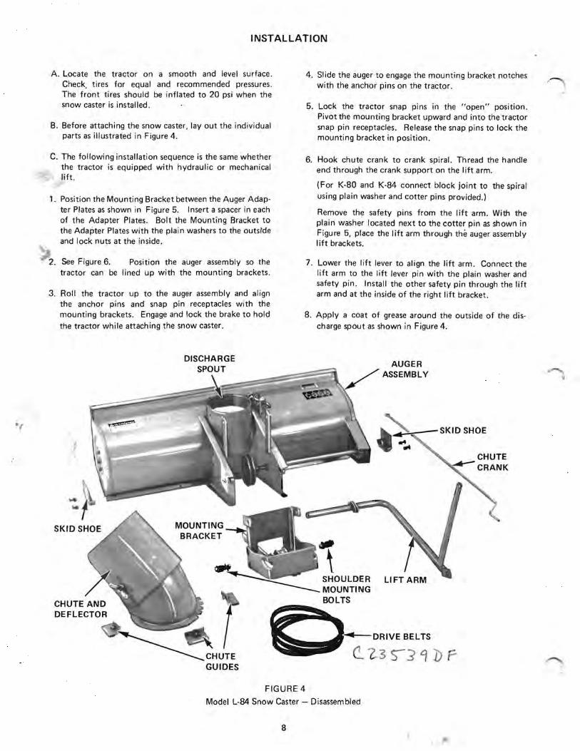
B. Before attaching the snow caster, layout the individual parts as illustrated in Figure 4.
C. The following installation sequence is the same whether the tractor is equipped with hydraulic or mechanical lift.
1. Position the Mounting Bracket between the Auger Adapter Plates as shown in Figure 5. Insert a spacer in each of the Adapter Plates. Bolt the Mounting Bracket to the Adapter Plates with the plain washers to the outsrde and lock nuts at the inside.
2. See Figure 6. Position the auger assembly so the tractor can be lined up with the mounting brackets .
3. Roll the tractor up to the auger assembly and align the anchor pins and snap pin receptacles with the mounting brackets. Engage and lock the brake to hold the tractor while attaching the snow caster.
.,
4. Slide the auger to engage the mounting bracket notches with the anchor pins on the tractor.
" 5. Lock the tractor snap pins in the "open" posItIOn.
Pivot the mounting bracket upward and into the tractor snap pin receptacles. Release the snap pins to lock the mounting bracket in position.
6. Hook chute crank to crank spiral. Thread the handle end through the crank support on the lift arm.
(For K-80 and K-84 connect block joint to the spiral using plain washer and cotter pins provided.)
Remove the safety pins from the Iift arm. With the plain washer located next to the cotter pin as shown in Figure 5, place the I ift arm through the auger assembly lift brackets.
7. Lower the lift lever to align the lift arm. Connect the lift arm to the lift lever pin with the plain washer and safety pin. Install the other safety pin through the lift arm and at the inside of the right lift bracket .
8. Apply a coat of grease around the outside of the discharge spout as shown in Figure 4.
~
lI
MOUNTING BRACKET
SHOULDER MOUNTING BOLTS
AUGER ASSEMBLY
.. ' -SKID SHOE
"~DRIVE BELTS
c.. 7.3 S-J 4 Df
FIGURE 4
Model L-84 Snow Caster - Disassembled
8 "\ .:-~

~--LIFTARM
NOTCHSKID SHOE MOUNTING BRACKET
CHUTE AND DEFLECTOR
ADAPTER PLATE MOUNTING BRACKET
FIGURE 5
Model L·84 Snow Caster - Assembled
9. Apply a coat of grease to both sides of the notched chute base ring. Place the chute over discharge spout and engage the base ring notches with the crank spiral.
10. Jhree round head bolts are furnished to attach the chute guides to the discharge spout. Install the bolts at the two side. guides with the round heads to the inside. For ease of assembly . install the front guide bolt with the nut and lockwasher to the inside.
NOTE Check to make certain the three guides are square with the chute base ring to prevent the chute from binding when turning the crank.
11 . Engage the attachment drive clutch. Raise the hood and remove the spark plug wire as a safety precaution . Insert the drive belt between the fan and heat exchanger and onto the attachment drive clutch pulley.
ANCHOR PIN
aRACKET
FIGURE 6 Model L·84 Snow Caster
9

NOTE Two belts are included with the 48" Model L84 Snow Caster to permit mounting on both high and low clearance tractors. If mounting this snow caster on a Model 444 or 446 tractor, use the longer of the two belts. Use the shorter of the two belts when mounting this snow caster on a Model 222 or 224 tractor _
12. See Figure 7_ Place the belt under the "fixed" idler pulley and around the "auger shaft" pulley _ Push down on the "spring idler" pulley lever and locate the belt on the underside . Check the belt to make certain it is correctly installed with the "vee" side in the vee groove pulleys and the "flat" side in the flat groove idler pulley.
13_ Disengage the attachment drive clutch and manually turn the auger to check the belt for proper operation . Reconnect the spark plug wire .
ATTACHMENT DRIVE CLUTCH
~
FIXED IDLER PULLEY
~
SPRING IDLER PULLEY
FIGURE 7
IMPORTANT Before operating the snow caster, review and follow the recommendations outlined in the Adjustments and Maintenance sections of this manual.
ADJUSTMENTS
1. Deflector - See Figure 8. The deflector has a slotted hole on each side for adjustment. To change the angle of the deflector, loosen the two locking wing nuts. By angl ing the deflector upward, the snow will be cast higher and further from the tractor. When angled downward, the deflector will direct the snow closer to the ground and it will be cast a shorter distance. tighten the locking wing nuts when the deflector is adjusted to the desired angle.
2. Skid Shoes - See Figure 8. Slotted mounting holes are provided to obtain the desired clearance between the base of the auger housing and the surface of the area to be cleared . When operating on a smooth surface such as cement or asphalt, the skid shoes can be set at the lower end of the slots. If operating on a rough surface such as gravel or earth, the skid shoes should be set at the upper end of the slots to prevent foreign material from entering and possibly damaging the snow caster.
DEFLECTOR W
AUGER DRIVE CHAIN ADJUSTMENT
FIGURE 8 Model L-84 Snow Caster
10
/

The heavy duty skid shoes can be rotated from one side of the caster to the other for increased life when the leading edges wear down.
The shoes can be installed with the skids facing either inward or outward . If the skids are installed inward they will protect the cutting edge by keeping it 3/16" higher than the skids when they are adjusted to the "minimum" clearance position. If the skids are installed inward the nuts and lockwashers must be to the inside to provide a "smooth" outside surface .
If the shoes are installed with the skids to the outside they can be adjusted further upward if desired to place the cutting edge in direct contact with a hard level surface. such as a concrete or asphalt driveway . If installed in this manner the nuts and lockwashers can be to the outside . This installation is not recommended when operating on dirt, gravel or uneven surfaces .
3. Cutting Edge - The replaceable cutting edge can also be reversed for increased life when the leading side wears down.
4. Auger Drive Chain Adjustment - The two auger mounting hubs have twelve holes in an eccentric circle around
the auger mounting shaft. The hubs also have an ori entation hole near the shaft. Chain slack at the lower section should be held to between 3/B" and 1 /2" under normal finger pressure midway between the drive sprockets.
When adjustment is necessary, remove the two bolts from the right hand mounting hub and rotate the hub in either direction until correct chain tension is obtained and reinstall the two bolts. Important - To keep the chain in line with the auger sprocket, rotate the left hand mounting hub to locate the orientation hole in the same position as the right hand hub.
Turn the auger to make certain there is no interference with the housing. If interference is encountered, remove the two bolts from the right hand mounting hub and rotate the hub in the opposite direction until correct tension is obtained. Reset the left hand hub to place the orientation hole in the same location as the right hand hub.
Should the available adjustment on the auger mounting hubs be used up, the overall chain length can be decreased by removing the offset (half) link from the chain .
MAINTENANCE
A CAUTION: Never attempt to servIce or make adjustments while the snow caster or tractor rs running.
Grease the discharge chute control crank, chute guides and the chute base ring. Figure B, daily to keep the crank turning freely.
Once a month during season or every 25 operating hours, lubricate the auger drive chain with Case Heavy Duty Chain and Cable Lubricant, or equivalent, available through your.Case Compact Tractor Dealer.
At the end of the snow season, the following steps are recommended:
1. Remove the snow '"ca§tef from tractor following the procedure outlined at the end of this manual.
2. Wash off any salt deposit which may have dried on the auger and chute. Paint or cover exposed metal with a light coat of oil. Case Touch-up Enamel is available through your Case Compact Tractor Dealer.
3 . Service the snow caster following lubrication instructions above. Oil the auger drive chain thoroughly using Case Chain and Cable Lubricant' to prevent rust from forming.
4. Store snow caster in a dry place.
REMOVING THE SNOW CASTER
1. Disconnect spark plug wire as a safety precautron, en gage the attachmenrdrive clutch .
2. Push the "spring idler" pulley to loosen and remove the belt . Disengage the clutch and reconnect the spark plug wire .
3. Disconnect the lift arm from the tractor lift lever. Re
move the safety pin from the front of the lift arm. Slide the lift arm part way out of the auger lift brackets to clear the tractor. Swing the lift arm with crank attached over the auger assembly.
4 . Pull the snap pins out to release the mounting bracket and back the tractor away.
PRINTED IN U_S.A.
NOTE The J I Case Company reserves the right to make improvements in design or changes in specifications at any time without incurring any obligation to install them on units previously sold .
U.S. Price $.40 12-78-RP-2000
11

. .~ .
-,- c
,, I
Printed In U. S. A.