smvt - phoenix pumps, inc. 3 turbine goulds water technology smvt sectional assembly item no....
TRANSCRIPT

SMVTVERTICAL MULTI-STAGE PUMP
TECHNICAL BROCHUREBSMVT

PAGE 2
TurbineGoulds Water Technology
SMVT PRODUCT LINE NUMBERING SYSTEM
The various versions of the SMVT line are identified by a product code number on the pump label. This number is also the catalog number for the pump. The meaning of each digit in the product code number is shown below.Note: Not all combinations are possible. Consult your Goulds Water Technology distributor.
Example Product Code: SM3A1J2C1VA
Product Line Flow Material Hz/RPM HP Driver Stages Seal Options Trim
A Trim D TrimB Trim E Special TrimC Trim
V = Vertical MountH = Horizontal Mount
1 = Standard 2B Crane Seal
A = 1, B = 2, C = 3, D = 4, E = 5, F = 6, G = 7,H = 8, J = 9, K = 10, L = 11, M = 12
1 = 1 PH ODP, 2 = 3 PH ODP, 3 = 3 PH 575 V ODP,4 = 1 PH TEFC, 5 = 3 PH TEFC, 6 = 3 PH 575 V TEFC,7 = 3 PH 415 V ODP, 8 = 3 PH 415 V TEFC
A = 3 HP, B = 5 HP, C = 7.5 HP, D = 10 HP, E = 15 HP, F = 20 HP, G = 25 HP, H = 30 HP, J = 40 HP, K = 50 HP, L = 60 HP, M = 75 HP
1 = 60 Hz, 3600 RPM; 2 = 50 Hz 2900 RPM
A = Standard construction with carbon steel casingD = Standard construction with SS casing
1 = 175 GPM, 2 = 230 GPM, 3 = 380 GPM, 4 = 480 GPM, 5 = 600 GPM, 6 = 700 GPM
SM = SMVT

PAGE 3
TurbineGoulds Water Technology
SMVT SECTIONAL ASSEMBLY
Item No. Description
1 Pump Body
1B Pipe Plug – Drain
2 Suction Cover
2A O-Ring – Suction Cover
3 Intermediate Bowl
3A Hex Screws – Bowl
4 Bearing
5 Impeller
6 Taperlock
7 Shaft
8 Casing
8A O-Ring – Casing
8B Hex Screws – Casing
9 Motor Support
9A Guard – Motor Support
9B Pipe Plug
9C Hex Screws – Motor Support
10 Mechanical Seal
10A Hex Screws – Seal
11 Coupling
11A Cap Screws – Coupling
11B Lock Washers – Coupling
11C Dowel Pin – Coupling
12 Motor
12A Hex Screws – Motor
13 Seal Plate

PAGE 4
TurbineGoulds Water Technology
MOTORSStandard motors supplied by Goulds Water Technology are NEMA standard TC frame motors open drip proof, or totally enclosed fan cooled enclosures. 60 Hz, 2-pole, three phase with 1.15 S.F. For other motor options, contact the factory.
DIMENSIONS AND WEIGHTS(All dimensions are in inches, weights are total unit weight.)
MODEL: SM1 60 HZGENERAL PUMP DESCRIPTION
Motor Dimensions (inches) Stage
Frame HP H1 H2 H3 M1 D1 D2 1 182TC 5 43.25 29.57 13.68 6.87 8.49 13.63 439 2 213TC 10 50.37 35.07 15.30 7.93 10.18 13.63 527 3 215TC 15 55.88 40.57 15.31 7.93 10.18 13.63 593 4 254TC 20 61.44 46.13 15.31 7.93 10.18 13.63 612 5 256TC 25 71.07 51.63 19.44 8.92 11.63 13.63 693 6 284TSC 30 77.69 57.13 20.56 8.94 11.50 13.63 797 7 286TSC 40 85.69 62.69 23.00 12.21 13.25 13.63 952 8 286TSC 40 91.25 68.25 23.00 12.21 13.25 13.63 1000
Wt.(lbs.)
ODP Motors
Motor Dimensions (inches) Stage
Frame HP H1 H2 H3 M1 D1 D2 1 184TC 5 44.75 29.57 15.18 6.87 8.60 13.63 439 2 215TC 10 52.07 35.07 17.00 8.05 10.62 13.63 536 3 215TC 15 57.57 40.57 17.00 8.05 10.62 13.63 666 4 256TC 20 68.1 46.13 21.97 10.04 12.94 13.63 687 5 284TSC 25 77.32 51.63 25.69 13.11 15.56 13.63 886 6 286TSC 30 82.82 57.13 25.69 13.11 15.56 13.63 965 7 286TSC 40 88.38 62.69 25.69 13.11 15.56 13.63 1138 8 286TSC 40 93.94 68.25 25.69 13.11 15.56 13.63 1154
Wt.(lbs.)
TEFC Motors
Motor dimensions are based on Goulds Water Technology's choice motors. Other manufacturer’s motor may have different dimensions.
Construction: Cast iron stainless steel fitted
Capacity: 50 – 225 GPM
Head: 50–880 feet
Staging: 1–8
Minimum flow: 50 GPM
Maximum working pressure:
175 PSI with ANSI Class 125 flange (up to 3 stage) 400 PSI with ANSI Class 250 flange (More than 3 stage)
Temperatures: Liquid temperature from -13°F (-25°C) to 150°F (65°C)
Solids handling:
Although not recommended, the pump may pass a 1⁄8" solid.
Piping Connections:
Suction and discharge openings are 3" with ANSI Class 125 or 250 flanges.
Component Description Material ASTM Spec.
Motor Support Cast Iron A48 Class 30
Shaft Coupling Cast Iron A48 Class 30
Mechanical SealType 316SS, Carbon Silicon Carbide
Seal Cover Cast Iron A48 Class 30
Casing Steel or Type 316SSA53 Grade A or A312 S31600
Casing and Suction O-ring
NitrileD2000 2BG715B14
Pump Shaft Type 416SS A582 S41600
Intermediate Bowl
Cast Iron A48 Class 30
Bowl Bearing Bronze B854 C90300
Impeller Type 316SS A744 CF8M
Taperlock Type 316SS A276 S31600
Suction Cover Cast Iron A48 Class 30
Pump Body Cast Iron A48 Class 30
Hex Head Capscrew
Steel SAE J429 Gr. 8
Socket Head Capscrew
Steel SAE J429 Gr. 8
Washer Steel A108 G10180
Pipe Plug Malleable Iron A197

PAGE 5
TurbineGoulds Water Technology
SM1 60 HZ PERFORMANCE CURVE3500 RPM CI/SS Construction
0
100
200
300
400
500
600
700
800
900
1000
0 50 100 150 200 250
50
60
70
80
0 50 100 150 200 2500
10
30
40
15 HP 3 Stage
10 HP 2 Stage
TOTA
L D
YN
AM
IC H
EA
D (F
EE
T)E
FFIC
IEN
CY
(%)
CAPACITY (U.S. GPM)
NP
SHR
(FE
ET)
SM160 Hz
3500 RPM
Efficiency
NPSHR
40 HP 8 Stage
40 HP 7 Stage
30 HP 6 Stage (A)
25 HP 5 Stage
30 HP 6 Stage (B)
20 HP 4 Stage
5 HP 1 Stage
40
20
Efficiency Correction1 - Stage -3.02 - Stage -2.03 - Stage -0.54 - Stage 0.0

PAGE 6
TurbineGoulds Water Technology
Motor Dimensions (inches) Stage
Frame HP H1 H2 H3 M1 D1 D2 1 184TC 7.5 43.25 29.57 13.68 6.87 8.94 13.63 445 2 215TC 15 50.38 35.07 15.31 7.93 10.18 13.63 545 3 254TC 20 55.88 40.57 15.31 7.93 10.18 13.63 612 3 256TC 25 60.01 40.57 19.44 8.92 11.63 13.63 645 4 256TC 25 65.57 46.13 19.44 8.92 11.63 13.63 692 4 284TSC 30 66.69 46.13 20.56 8.94 11.50 13.63 750 5 284TSC 30 72.19 51.63 20.56 8.94 11.50 13.63 797 5 286TSC 40 74.63 51.63 23.00 12.21 13.25 13.63 857 6 286TSC 40 80.13 57.13 23.00 12.21 13.25 13.63 904 6 286TSC 50 80.13 57.13 23.00 12.21 13.25 13.63 997 7 286TSC 50 85.69 62.69 23.00 12.21 13.25 13.63 1044
Wt.(lbs.)
ODP Motors
Motor Dimensions (inches) Stage
Frame HP H1 H2 H3 M1 D1 D2 1 184TC 7.5 44.75 29.57 15.18 8.05 10.62 13.63 469 2 215TC 15 52.07 35.07 17.00 8.05 10.62 13.63 618 3 256TC 20 62.54 40.57 21.97 10.04 12.94 13.63 687 3 284TSC 25 66.26 40.57 25.69 13.11 15.56 13.63 871 4 284TSC 25 71.82 46.13 25.69 13.11 15.56 13.63 918 4 286TSC 30 71.82 46.13 25.69 13.11 15.56 13.63 918 5 286TSC 30 77.32 51.63 25.69 13.11 15.56 13.63 965 5 286TSC 40 77.32 51.63 25.69 13.11 15.56 13.63 1043 6 286TSC 40 82.82 57.13 25.69 13.11 15.56 13.63 1090 6 326TSC 50 84.92 57.13 27.79 14.12 17.35 13.63 1205 7 326TSC 50 90.48 62.69 27.79 14.12 17.35 13.63 1252
Wt.(lbs.)
TEFC Motors
Motor dimensions are based on Goulds Water Technology’s choice motors. Other manufacturer’s motor may have different dimensions.
DIMENSIONS AND WEIGHTS(All dimensions are in inches, weights are total unit weight.)
MODEL: SM2 60 HZGENERAL PUMP DESCRIPTION
Construction: Cast iron stainless steel fitted
Capacity: 50 – 300 GPM
Head: 80–880 feet
Staging: 1–7
Minimum flow: 50 GPM
Maximum working pressure:
175 PSI with ANSI Class 125 flange (up to 3 stage) 400 PSI with ANSI Class 250 flange (More than 3 stage)
Temperatures: Liquid temperature from -13°F (-25°C) to 150°F (65°C)
Solids handling:
Although not recommended, the pump may pass a ¼" solid.
Piping Connections:
Suction and discharge openings are 3" with ANSI Class 125 or 250 flanges.
Component Description Material ASTM Spec.
Motor Support Cast Iron A48 Class 30
Shaft Coupling Cast Iron A48 Class 30
Mechanical SealType 316SS, Carbon Silicon Carbide
Seal Cover Cast Iron A48 Class 30
Casing Steel or Type 316SSA53 Grade A or A312 S31600
Casing and Suction O-ring
NitrileD2000 2BG715B14
Pump Shaft Type 416SS A582 S41600
Intermediate Bowl
Cast Iron A48 Class 30
Bowl Bearing Bronze B854 C90300
Impeller Type 316SS A744 CF8M
Taperlock Type 316SS A276 S31600
Suction Cover Cast Iron A48 Class 30
Pump Body Cast Iron A48 Class 30
Hex Head Capscrew
Steel SAE J429 Gr. 8
Socket Head Capscrew
Steel SAE J429 Gr. 8
Washer Steel A108 G10180
Pipe Plug Malleable Iron A197
MOTORSStandard motors supplied by Goulds Water Technology are NEMA standard TC frame motors open drip proof, or totally enclosed fan cooled enclosures. 60 Hz, 2-pole, three phase with 1.15 S.F. For other motor options, contact the factory.
PAGE 7
TurbineGoulds Water Technology
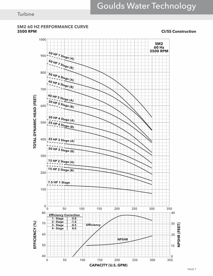
SM2 60 HZ PERFORMANCE CURVE3500 RPM CI/SS Construction
0
100
200
300
400
500
600
700
800
900
1000
0 50 100 150 200 250 300 350
50
60
70
80
0 50 100 150 200 250 300 3500
10
30
40
7.5 HP 1 Stage
SM260 Hz
3500 RPM
15 HP 2 Stage (B)
15 HP 2 Stage (A)
20 HP 3 Stage (B)
25 HP 3 Stage (A)
25 HP 4 Stage (B)
30 HP 4 Stage (A)
30 HP 5 Stage (B)
40 HP 5 Stage (A)
40 HP 6 Stage (B)
50 HP 6 Stage (A)
50 HP 7 Stage (B)
50 HP 7 Stage (A)
40
20
TOTA
L D
YN
AM
IC H
EA
D (F
EE
T)E
FFIC
IEN
CY
(%)
CAPACITY (U.S. GPM)
NP
SHR
(FE
ET)Efficiency
NPSHR
Efficiency Correction1 - Stage -2.02 - Stage -1.53 - Stage -0.54 - Stage 0.0
PAGE 8
TurbineGoulds Water Technology
Motor Dimensions (inches) Stage
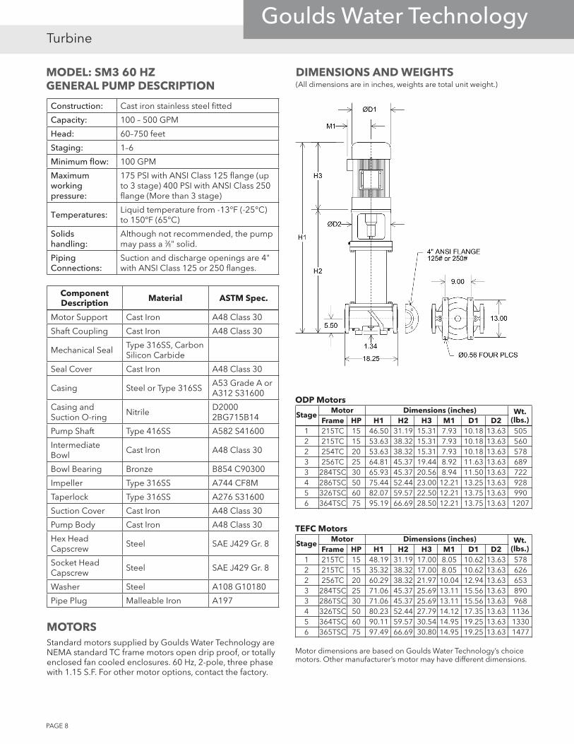
Frame HP H1 H2 H3 M1 D1 D2 1 215TC 15 46.50 31.19 15.31 7.93 10.18 13.63 505 2 215TC 15 53.63 38.32 15.31 7.93 10.18 13.63 560 2 254TC 20 53.63 38.32 15.31 7.93 10.18 13.63 578 3 256TC 25 64.81 45.37 19.44 8.92 11.63 13.63 689 3 284TSC 30 65.93 45.37 20.56 8.94 11.50 13.63 722 4 286TSC 50 75.44 52.44 23.00 12.21 13.25 13.63 928 5 326TSC 60 82.07 59.57 22.50 12.21 13.75 13.63 990 6 364TSC 75 95.19 66.69 28.50 12.21 13.75 13.63 1207
Wt.(lbs.)
ODP Motors
Motor Dimensions (inches) Stage
Frame HP H1 H2 H3 M1 D1 D2 1 215TC 15 48.19 31.19 17.00 8.05 10.62 13.63 578 2 215TC 15 35.32 38.32 17.00 8.05 10.62 13.63 626 2 256TC 20 60.29 38.32 21.97 10.04 12.94 13.63 653 3 284TSC 25 71.06 45.37 25.69 13.11 15.56 13.63 890 3 286TSC 30 71.06 45.37 25.69 13.11 15.56 13.63 968 4 326TSC 50 80.23 52.44 27.79 14.12 17.35 13.63 1136 5 364TSC 60 90.11 59.57 30.54 14.95 19.25 13.63 1330 6 365TSC 75 97.49 66.69 30.80 14.95 19.25 13.63 1477
Wt.(lbs.)
TEFC Motors
Motor dimensions are based on Goulds Water Technology’s choice motors. Other manufacturer’s motor may have different dimensions.
DIMENSIONS AND WEIGHTS(All dimensions are in inches, weights are total unit weight.)
MODEL: SM3 60 HZGENERAL PUMP DESCRIPTION
Construction: Cast iron stainless steel fitted
Capacity: 100 – 500 GPM
Head: 60–750 feet
Staging: 1–6
Minimum flow: 100 GPM
Maximum working pressure:
175 PSI with ANSI Class 125 flange (up to 3 stage) 400 PSI with ANSI Class 250 flange (More than 3 stage)
Temperatures: Liquid temperature from -13°F (-25°C) to 150°F (65°C)
Solids handling:
Although not recommended, the pump may pass a 3⁄8" solid.
Piping Connections:
Suction and discharge openings are 4" with ANSI Class 125 or 250 flanges.
Component Description Material ASTM Spec.
Motor Support Cast Iron A48 Class 30
Shaft Coupling Cast Iron A48 Class 30
Mechanical SealType 316SS, Carbon Silicon Carbide
Seal Cover Cast Iron A48 Class 30
Casing Steel or Type 316SSA53 Grade A or A312 S31600
Casing and Suction O-ring
NitrileD2000 2BG715B14
Pump Shaft Type 416SS A582 S41600
Intermediate Bowl
Cast Iron A48 Class 30
Bowl Bearing Bronze B854 C90300
Impeller Type 316SS A744 CF8M
Taperlock Type 316SS A276 S31600
Suction Cover Cast Iron A48 Class 30
Pump Body Cast Iron A48 Class 30
Hex Head Capscrew
Steel SAE J429 Gr. 8
Socket Head Capscrew
Steel SAE J429 Gr. 8
Washer Steel A108 G10180
Pipe Plug Malleable Iron A197
MOTORSStandard motors supplied by Goulds Water Technology are NEMA standard TC frame motors open drip proof, or totally enclosed fan cooled enclosures. 60 Hz, 2-pole, three phase with 1.15 S.F. For other motor options, contact the factory.

PAGE 9
TurbineGoulds Water Technology
SM3 60 HZ PERFORMANCE CURVE3500 RPM CI/SS Construction
0
100
200
300
400
500
600
700
900
60
70
80
0 100 200 300 400 5000
10
20
40
0 100 200 300 400 500
SM360 Hz
3500 RPM
800
50 150 250 350 450
15 HP 1 Stage
15 HP 2 Stage (B)
20 HP 2 Stage (A)
25 HP 3 Stage (B)
30 HP 3 Stage (A)
50 HP 4 Stage
60 HP 5 Stage
75 HP 6 Stage
50
30
90
TOTA
L D
YN
AM
IC H
EA
D (F
EE
T)E
FFIC
IEN
CY
(%)
CAPACITY (U.S. GPM)
NP
SHR
(FE
ET)
Efficiency
NPSHR
Efficiency Correction1 - Stage -5.52 - Stage -2.53 - Stage -1.04 - Stage 0.0

PAGE 10
TurbineGoulds Water Technology
Motor Dimensions (inches) Stage
Frame HP H1 H2 H3 M1 D1 D2 1 215TC 15 45.75 30.44 15.31 7.93 10.18 13.63 499 1 254TC 20 45.75 30.44 15.31 7.93 10.18 13.63 518 2 256TC 25 56.26 36.82 19.44 8.92 11.63 13.63 600 2 284TSC 30 57.38 36.82 20.56 8.94 11.50 13.63 657 2 286TSC 40 65.26 36.82 23.00 12.21 13.25 13.63 717 3 286TSC 40 66.22 43.22 23.00 12.21 13.25 13.63 765 3 286TSC 50 66.215 43.22 23.00 12.21 13.25 13.63 857 3 326TSC 60 71.07 43.22 22.50 12.21 13.75 13.63 865 4 364TSC 75 78.13 49.63 28.50 12.21 19.25 13.63 1024
Wt.(lbs.)
ODP Motors
Motor Dimensions (inches) Stage
Frame HP H1 H2 H3 M1 D1 D2 1 215TC 15 47.44 30.44 17.00 8.05 10.62 13.63 572 1 256TC 20 52.41 30.44 21.97 10.04 12.94 13.63 593 2 284TSC 25 62.51 36.82 25.69 13.11 15.56 13.63 793 2 286TSC 30 62.51 36.82 25.69 13.11 15.56 13.63 825 2 286TSC 40 67.95 36.82 25.69 13.11 15.56 13.63 903 3 286TSC 40 68.91 43.22 25.69 13.11 15.56 13.63 951 3 326TSC 50 71.01 43.22 27.79 14.12 17.35 13.63 1065 3 364TSC 60 79.11 43.22 30.54 14.95 19.25 13.63 1205 4 365TSC 75 80.43 49.63 30.80 14.95 19.25 13.63 1294
Wt.(lbs.)
TEFC Motors
Motor dimensions are based on Goulds Water Technology’s choice motors. Other manufacturer’s motor may have different dimensions.
DIMENSIONS AND WEIGHTS(All dimensions are in inches, weights are total unit weight.)
MODEL: SM4 60 HZGENERAL PUMP DESCRIPTION
Construction: Cast iron stainless steel fitted
Capacity: 200 – 600 GPM
Head: 70–520 feet
Staging: 1–4
Minimum flow: 200 GPM
Maximum working pressure:
175 PSI with ANSI Class 125 flange (up to 3 stage) 400 PSI with ANSI Class 250 flange (4 stage)
Temperatures: Liquid temperature from -13°F (-25°C) to 150°F (65°C)
Solids handling:
Although not recommended, the pump may pass a 3⁄8" solid.
Piping Connections:
Suction and discharge openings are 4" with ANSI Class 125 or 250 flanges.
Component Description Material ASTM Spec.
Motor Support Cast Iron A48 Class 30
Shaft Coupling Cast Iron A48 Class 30
Mechanical SealType 316SS, Carbon Silicon Carbide
Seal Cover Cast Iron A48 Class 30
Casing Steel or Type 316SSA53 Grade A or A312 S31600
Casing and Suction O-ring
NitrileD2000 2BG715B14
Pump Shaft Type 416SS A582 S41600
Intermediate Bowl
Cast Iron A48 Class 30
Bowl Bearing Bronze B854 C90300
Impeller Type 316SS A744 CF8M
Taperlock Type 316SS A276 S31600
Suction Cover Cast Iron A48 Class 30
Pump Body Cast Iron A48 Class 30
Hex Head Capscrew
Steel SAE J429 Gr. 8
Socket Head Capscrew
Steel SAE J429 Gr. 8
Washer Steel A108 G10180
Pipe Plug Malleable Iron A197
MOTORSStandard motors supplied by Goulds Water Technology are NEMA standard TC frame motors open drip proof, or totally enclosed fan cooled enclosures. 60 Hz, 2-pole, three phase with 1.15 S.F. For other motor options, contact the factory.

PAGE 11
TurbineGoulds Water Technology
SM4 60 HZ PERFORMANCE CURVE3500 RPM CI/SS Construction
0
100
200
300
400
500
600
50
60
70
90
0 100 200 300 400 500 70010
20
30
500 100 200 300 400 500 700
SM460 Hz
3500 RPM
600
15 HP 1 Stage (B)
20 HP 1 Stage (A)
25 HP 2 Stage (C)
30 HP 2 Stage (B)
40 HP 2 Stage (A)
40 HP 3 Stage (C)
50 HP 3 Stage (B)
75 HP 4 Stage (A)
75 HP 4 Stage (B)
60 HP 3 Stage (A)
80
600
40
TOTA
L D
YN
AM
IC H
EA
D (F
EE
T)E
FFIC
IEN
CY
(%)
CAPACITY (U.S. GPM)
NP
SHR
(FE
ET)Efficiency
NPSHR
Efficiency Correction1 - Stage -5.02 - Stage -2.03 - Stage 0.0

PAGE 12
TurbineGoulds Water Technology
Motor Dimensions (inches) Stage
Frame HP H1 H2 H3 M1 D1 D2 1 213TC 10 46.49 31.19 15.30 7.93 10.18 13.63 487 1 215TC 15 46.50 31.19 15.31 7.93 10.18 13.63 505 2 254TC 20 53.63 38.32 15.31 7.93 10.18 13.63 578 2 256TC 25 57.76 38.32 19.44 8.92 11.63 13.63 611 3 284TSC 30 65.93 45.37 20.56 8.94 11.50 13.63 722 3 286TSC 40 68.37 45.37 23.00 12.21 13.25 13.63 782 4 286TSC 40 75.44 52.44 23.00 12.21 13.25 13.63 836 4 286TSC 50 75.44 52.44 23.00 12.21 13.25 13.63 928 5 326TSC 60 82.06 59.56 22.50 12.21 13.75 13.63 1082 6 364TSC 75 95.19 66.69 28.50 12.21 19.25 13.63 1207
Wt.(lbs.)
ODP Motors
Motor Dimensions (inches) Stage
Frame HP H1 H2 H3 M1 D1 D2 1 215TC 10 48.19 31.19 17.00 8.05 10.62 13.63 496 1 215TC 15 48.19 31.19 17.00 8.05 10.62 13.63 578 2 256TC 20 60.29 38.32 21.97 10.04 12.94 13.63 653 2 284TSC 25 64.01 38.32 25.69 13.11 15.56 13.63 804 3 286TSC 30 71.06 45.37 25.69 13.11 15.56 13.63 890 3 286TSC 40 71.06 45.37 25.69 13.11 15.56 13.63 968 4 286TSC 40 78.13 52.44 25.69 13.11 15.56 13.63 1022 4 326TSC 50 80.23 52.44 27.79 14.12 17.35 13.63 1136 5 364TSC 60 90.36 59.56 30.80 14.95 19.25 13.63 1330 6 365TSC 75 97.49 66.69 30.80 14.95 19.25 13.63 1477
Wt.(lbs.)
TEFC Motors
Motor dimensions are based on Goulds Water Technology’s choice motors. Other manufacturer’s motor may have different dimensions.
DIMENSIONS AND WEIGHTS(All dimensions are in inches, weights are total unit weight.)
MODEL: SM5 60 HZGENERAL PUMP DESCRIPTION
Construction: Cast iron stainless steel fitted
Capacity: 200 – 700 GPM
Head: 40–600 feet
Staging: 1–6
Minimum flow: 200 GPM
Maximum working pressure:
175 PSI with ANSI Class 125 flange (up to 4 stage) 400 PSI with ANSI Class 250 flange (5 and 6 stage)
Temperatures: Liquid temperature from -13°F (-25°C) to 150°F (65°C)
Solids handling:
Although not recommended, the pump may pass a ½" solid.
Piping Connections:
Suction and discharge openings are 4" with ANSI Class 125 or 250 flanges.
Component Description Material ASTM Spec.
Motor Support Cast Iron A48 Class 30
Shaft Coupling Cast Iron A48 Class 30
Mechanical SealType 316SS, Carbon Silicon Carbide
Seal Cover Cast Iron A48 Class 30
Casing Steel or Type 316SSA53 Grade A or A312 S31600
Casing and Suction O-ring
NitrileD2000 2BG715B14
Pump Shaft Type 416SS A582 S41600
Intermediate Bowl
Cast Iron A48 Class 30
Bowl Bearing Bronze B854 C90300
Impeller Type 316SS A744 CF8M
Taperlock Type 316SS A276 S31600
Suction Cover Cast Iron A48 Class 30
Pump Body Cast Iron A48 Class 30
Hex Head Capscrew
Steel SAE J429 Gr. 8
Socket Head Capscrew
Steel SAE J429 Gr. 8
Washer Steel A108 G10180
Pipe Plug Malleable Iron A197
MOTORSStandard motors supplied by Goulds Water Technology are NEMA standard TC frame motors open drip proof, or totally enclosed fan cooled enclosures. 60 Hz, 2-pole, three phase with 1.15 S.F. For other motor options, contact the factory.
PAGE 13
TurbineGoulds Water Technology
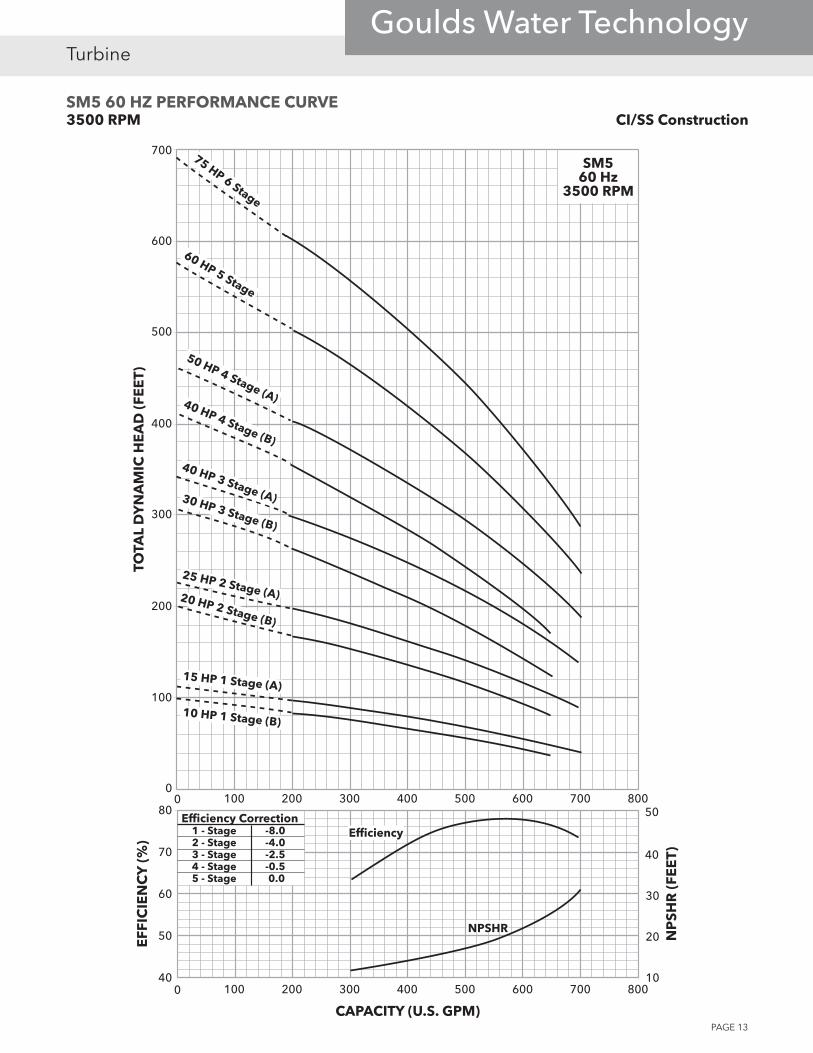
SM5 60 HZ PERFORMANCE CURVE3500 RPM CI/SS Construction
0
100
200
300
400
500
600
700
40
60
70
80
0 100 200 300 400 500 600 80010
40
500 100 200 300 400 500 600 800
SM560 Hz
3500 RPM
700
700
50 20
30
75 HP 6 Stage
60 HP 5 Stage
50 HP 4 Stage (A)40 HP 4 Stage (B)
40 HP 3 Stage (A)30 HP 3 Stage (B)
25 HP 2 Stage (A)20 HP 2 Stage (B)
15 HP 1 Stage (A)
10 HP 1 Stage (B)
TOTA
L D
YN
AM
IC H
EA
D (F
EE
T)E
FFIC
IEN
CY
(%)
CAPACITY (U.S. GPM)
NP
SHR
(FE
ET)
Efficiency
NPSHR
Efficiency Correction1 - Stage -8.02 - Stage -4.03 - Stage -2.54 - Stage -0.55 - Stage 0.0
PAGE 14
TurbineGoulds Water Technology
Motor Dimensions (inches) Stage
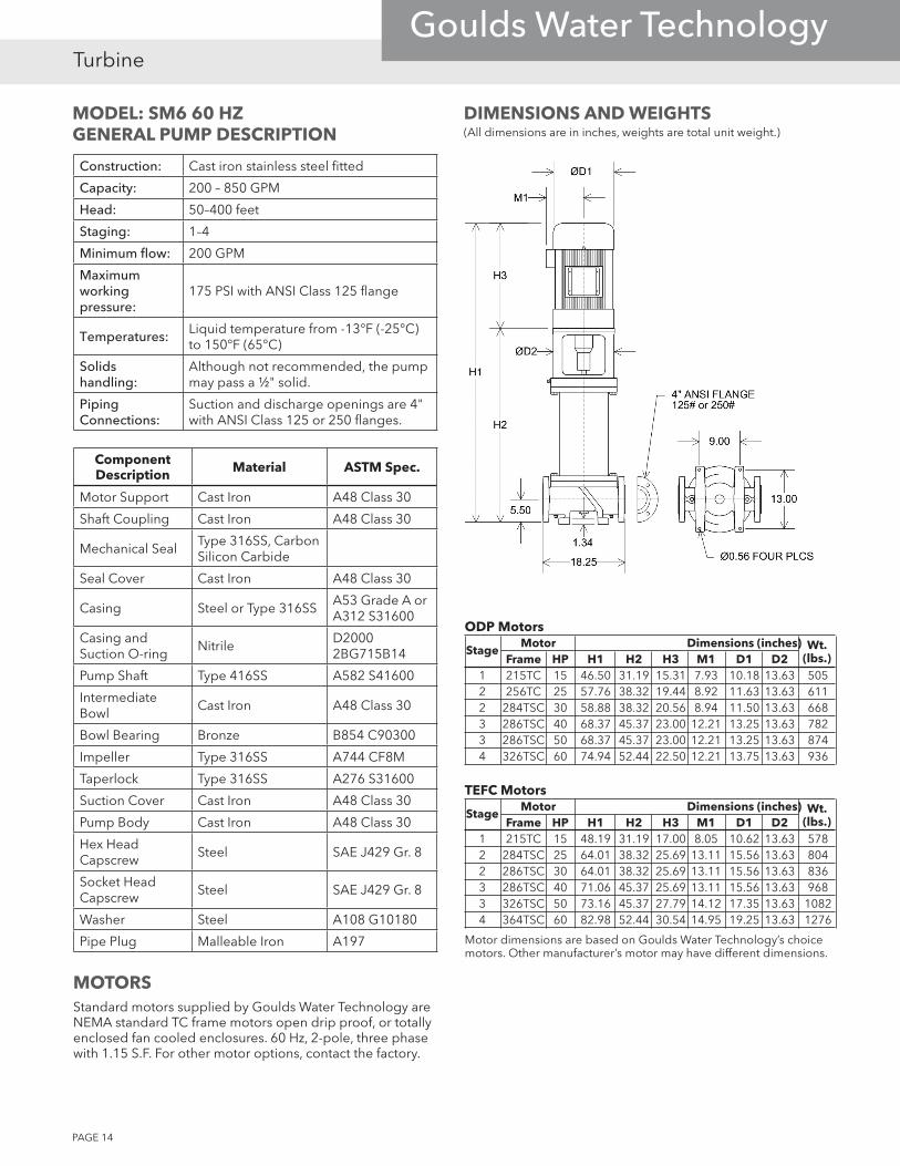
Frame HP H1 H2 H3 M1 D1 D2 1 215TC 15 46.50 31.19 15.31 7.93 10.18 13.63 505 2 256TC 25 57.76 38.32 19.44 8.92 11.63 13.63 611 2 284TSC 30 58.88 38.32 20.56 8.94 11.50 13.63 668 3 286TSC 40 68.37 45.37 23.00 12.21 13.25 13.63 782 3 286TSC 50 68.37 45.37 23.00 12.21 13.25 13.63 874 4 326TSC 60 74.94 52.44 22.50 12.21 13.75 13.63 936
Wt.(lbs.)
ODP Motors
Motor Dimensions (inches) Stage
Frame HP H1 H2 H3 M1 D1 D2 1 215TC 15 48.19 31.19 17.00 8.05 10.62 13.63 578 2 284TSC 25 64.01 38.32 25.69 13.11 15.56 13.63 804 2 286TSC 30 64.01 38.32 25.69 13.11 15.56 13.63 836 3 286TSC 40 71.06 45.37 25.69 13.11 15.56 13.63 968 3 326TSC 50 73.16 45.37 27.79 14.12 17.35 13.63 1082 4 364TSC 60 82.98 52.44 30.54 14.95 19.25 13.63 1276
Wt.(lbs.)
TEFC Motors
Motor dimensions are based on Goulds Water Technology’s choice motors. Other manufacturer’s motor may have different dimensions.
DIMENSIONS AND WEIGHTS(All dimensions are in inches, weights are total unit weight.)
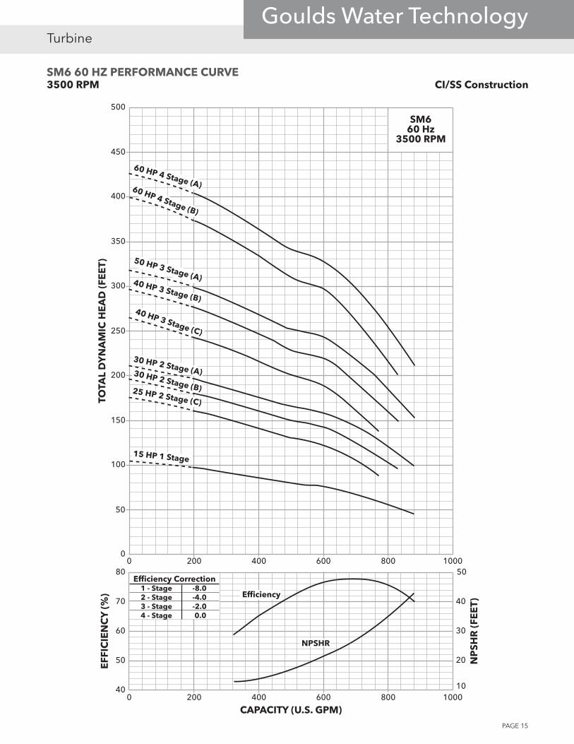
MODEL: SM6 60 HZGENERAL PUMP DESCRIPTION
Construction: Cast iron stainless steel fitted
Capacity: 200 – 850 GPM
Head: 50–400 feet
Staging: 1–4
Minimum flow: 200 GPM
Maximum working pressure:
175 PSI with ANSI Class 125 flange
Temperatures: Liquid temperature from -13°F (-25°C) to 150°F (65°C)
Solids handling:
Although not recommended, the pump may pass a ½" solid.
Piping Connections:
Suction and discharge openings are 4" with ANSI Class 125 or 250 flanges.
Component Description Material ASTM Spec.
Motor Support Cast Iron A48 Class 30
Shaft Coupling Cast Iron A48 Class 30
Mechanical SealType 316SS, Carbon Silicon Carbide
Seal Cover Cast Iron A48 Class 30
Casing Steel or Type 316SSA53 Grade A or A312 S31600
Casing and Suction O-ring
NitrileD2000 2BG715B14
Pump Shaft Type 416SS A582 S41600
Intermediate Bowl
Cast Iron A48 Class 30
Bowl Bearing Bronze B854 C90300
Impeller Type 316SS A744 CF8M
Taperlock Type 316SS A276 S31600
Suction Cover Cast Iron A48 Class 30
Pump Body Cast Iron A48 Class 30
Hex Head Capscrew
Steel SAE J429 Gr. 8
Socket Head Capscrew
Steel SAE J429 Gr. 8
Washer Steel A108 G10180
Pipe Plug Malleable Iron A197
MOTORSStandard motors supplied by Goulds Water Technology are NEMA standard TC frame motors open drip proof, or totally enclosed fan cooled enclosures. 60 Hz, 2-pole, three phase with 1.15 S.F. For other motor options, contact the factory.
PAGE 15
TurbineGoulds Water Technology
SM6 60 HZ PERFORMANCE CURVE3500 RPM CI/SS Construction
0
50
100
150
200
250
300
350
400
450
500
40
60
70
80
0 200 400 600 800 100010
30
20
500 200 400 600 800 1000
SM660 Hz
3500 RPM
15 HP 1 Stage
50
40
30 HP 2 Stage (A)30 HP 2 Stage (B)25 HP 2 Stage (C)
40 HP 3 Stage (C)
40 HP 3 Stage (B)
50 HP 3 Stage (A)
60 HP 4 Stage (B)
60 HP 4 Stage (A)
TOTA
L D
YN
AM
IC H
EA
D (F
EE
T)E
FFIC
IEN
CY
(%)
CAPACITY (U.S. GPM)
NP
SHR
(FE
ET)
Efficiency
NPSHR
Efficiency Correction1 - Stage -8.02 - Stage -4.03 - Stage -2.04 - Stage 0.0
SMVT FEATURES AND BENEFITS
All units:
Flow range: 50 GPM through 850 GPM
Heads Range: Up to 880'
Efficiencies: Up to 80%
Proven turbine pump design for high efficiencies and durability
Vertical unit - excellent for limited space installations
Vertical and Horizontal pump offering
Standard Goulds Water Technology turbine parts used, for quicker repair and repair part delivery
Quality John Crane 2B Cartridge Mechanical Seal
Precision balanced rotating elements
Will Pass up to ½" solids depending upon the particular model
Motor available in ODP or TEFC enclosure
Temperature: From –13º F to 150º F for standard construction
Construction:Heavy duty construction for longer service life
Materials: Standard Cast Iron / Stainless Steel Fitted Construction with bronze bearings Optional Stainless Steel casing
Principal Markets:Commercial Applications Booster Units High Rise Building Water Applications HVAC
Municipal Applications Package Pump Stations, Booster Stations Water Treatment Applications
Irrigation Applications Turf Irrigation, Golf Courses, Stadiums Nurseries, Greenhouses, Sprinkler Systems
Xylem, Inc.P.O. Box 5487Lubbock, TX 79408Phone: (806) 763-7867 Fax: (800) 453-4749www.xyleminc.com/brands/gouldswatertechnology
Goulds is a registered trademark of Goulds Pumps, Inc. and is used under license. CentriPro and Aquavar SOLO are trademarks of Xylem Inc. or one of its subsidiaries.
© 2012 Xylem Inc. BSMVT August 2009