sms software user's guide - eyeonsystem files/sms user guide issue 6 2.pdf · additional card...
TRANSCRIPT

SMS SoftwareUser's Guide
SECURITY MANAGEMENT SYSTEM
9600-0429

© G4S Technology Ltd. 2009
All rights reserved. No part of this publication may be reproduced in any form without the written permissionof G4S Technology Ltd.
Challenge HouseInternational DriveTewkesburyGlosGL20 8UQUK
Telephone: +44 (0) 1684 850977
Security Management System User's Guide
v6.2 – 30th September 2009
Stock number: 9600-0429
Microsoft and Windows are registered trademarks of Microsoft Corporation.BACnet is a registered trademark of ASHRAE.Crystal Reports is a registered trademark of Crystal Decisions.Image compression software is based in part on the work of the Independent JPEG Group.Philips and MIFARE are registered trademarks of Philips Electronics N.V.HID is a registered trademark of HID Corporation.iCLASS is a trademark of HID Corporation.Texas Instruments is a trademark of Texas Instruments Incorporated.Fault Tolerant Streaming is a trademark of G4S Technology Ltd.GCS, GCS TopGuard and ProxiPen are registered trademarks of GCS.All other brand names are trademarks of their respective owners.
MPEG-4 Video components powered by ATEME
Security Management System User’s Guide i
Contents1 Preface ............................................................................................................................ iv
1 Chapter 1: Introduction to Security Management......................................................1-1About the Security Management System...............................................................................................1-1
Purpose............................................................................................................................................1-1Security Management Software ......................................................................................................1-1Doors...............................................................................................................................................1-1Gaining Access ...............................................................................................................................1-1Alarms and Events ..........................................................................................................................1-2System Configuration......................................................................................................................1-2Reporting.........................................................................................................................................1-2System Partitioning (Multiple Companies).....................................................................................1-3Standard Features............................................................................................................................1-3Optional Features ............................................................................................................................1-3
The Components of a Security Management System...........................................................................1-4Card Readers...................................................................................................................................1-4Exit-Request Buttons ......................................................................................................................1-4Door Lock .......................................................................................................................................1-5Door Monitors.................................................................................................................................1-5The Server and Client PCs..............................................................................................................1-5Printer..............................................................................................................................................1-5Controllers (Nodes).........................................................................................................................1-6Modems...........................................................................................................................................1-6Monitor Points ................................................................................................................................1-6Auxiliary outputs.............................................................................................................................1-6CCTV and Digital Video Systems ..................................................................................................1-7Intruder/Alarm Panels .....................................................................................................................1-7Intercom Systems ............................................................................................................................1-7
Product Types ..........................................................................................................................................1-8Business Edition Systems ...............................................................................................................1-8Professional Edition Systems..........................................................................................................1-8Enterprise Edition Systems .............................................................................................................1-8Global Edition Systems...................................................................................................................1-8
2 Chapter 2: Getting Started...........................................................................................2-1Starting the Security Management Software ........................................................................................2-1About the User Interface.........................................................................................................................2-2
Selection and Definition Screens ....................................................................................................2-3About your User Permissions .................................................................................................................2-3What you need to do next........................................................................................................................2-4
3 Chapter 3: Card Administration ..................................................................................3-1About the Card Holders Screen .............................................................................................................3-1
Creating or Finding a Card Holder .................................................................................................3-1Last Name, First Name and Middle Name......................................................................................3-3

Contents
ii Security Management System User’s Guide
Card Number .................................................................................................................................. 3-3Setting Up Card Details.......................................................................................................................... 3-4
Card Holder's Picture ..................................................................................................................... 3-4Active and Inactive Dates............................................................................................................... 3-4PIN Code........................................................................................................................................ 3-5Facility/Customer Code.................................................................................................................. 3-5Badge Design and Badge Expires .................................................................................................. 3-5Additional Card Options ................................................................................................................ 3-5Card Status ..................................................................................................................................... 3-5
Creating and Assigning Access Rights .................................................................................................. 3-6Defining Time Codes and Hours.................................................................................................... 3-7Defining Holidays .......................................................................................................................... 3-9
Specifying Personal Data...................................................................................................................... 3-11Locating a Card Holder........................................................................................................................ 3-12
4 Chapter 4: Producing ID Badges.................................................................................4-1Introduction............................................................................................................................................. 4-1Designing Badges .................................................................................................................................... 4-1Producing a Card Holder's Badge......................................................................................................... 4-3
Entering Card Details and Capturing the Card Holder's Picture .................................................... 4-3Approving Official ......................................................................................................................... 4-3Capturing the Card Holder's Signature........................................................................................... 4-3Capturing Fingerprint and Hand Geometry Data ........................................................................... 4-4Selecting and Previewing the Badge Design.................................................................................. 4-4Printing and Encoding the Badge................................................................................................... 4-5Smart Card Button.......................................................................................................................... 4-6
5 Chapter 5: Visitor Management...................................................................................5-1Setting Up Visitors .................................................................................................................................. 5-1Visitor Details .......................................................................................................................................... 5-2Personal Details ....................................................................................................................................... 5-2Visitor Card Details, Access Rights and Biometrics ............................................................................ 5-2Visitor Reports ........................................................................................................................................ 5-3
6 Chapter 6: Digital Video Management ........................................................................6-1Introduction............................................................................................................................................. 6-1Summary of Key Features...................................................................................................................... 6-1Using the Virtual Matrix Screen............................................................................................................ 6-3Using the Video Playback Screen .......................................................................................................... 6-4Identity Verification................................................................................................................................ 6-5
Using the Find Button .................................................................................................................... 6-6Video Storage Management Module ..................................................................................................... 6-7Using CCTV Switchers and Cameras ................................................................................................... 6-8
Viewing a CCTV Image During Alarm Acknowledgement .......................................................... 6-8Digital Video and CCTV Switcher Commands.................................................................................... 6-9

Contents
Security Management System User’s Guide iii
Digital Video Camera Commands ..................................................................................................6-9CCTV Switcher Commands............................................................................................................6-9
Playback from Alarms and Reports.......................................................................................................6-9Graphics Integration .............................................................................................................................6-10
7 Chapter 7: Alarms Monitoring .....................................................................................7-1Understanding Alarms Monitoring........................................................................................................7-1
How New Alarms are Signaled.......................................................................................................7-1The Steps to Take When an Alarm Occurs...........................................................................................7-2
Viewing the Details of an Alarm ....................................................................................................7-2Setting Up Alarm Filters .................................................................................................................7-3Viewing a Graphic of the Alarm's Location....................................................................................7-4Acknowledging an Alarm...............................................................................................................7-4Resetting the Alarm ........................................................................................................................7-5Clearing the Alarm..........................................................................................................................7-5
8 Chapter 8: Producing Reports ....................................................................................8-1Introduction .............................................................................................................................................8-1Activity Reports .......................................................................................................................................8-1History Reports........................................................................................................................................8-2Locator Reports .......................................................................................................................................8-3Card Reports............................................................................................................................................8-3Access Reports .........................................................................................................................................8-4Visitor Reports .........................................................................................................................................8-4Configuration Reports ............................................................................................................................8-5Muster (Roll Call) Reports .....................................................................................................................8-6
Muster Report Configuration ..........................................................................................................8-6Monitoring a Muster .......................................................................................................................8-7
9 Chapter 9: Other Features ...........................................................................................9-1Setting Up User Roles and Accounts......................................................................................................9-1
Setting Up Roles .............................................................................................................................9-1Creating User Accounts ..................................................................................................................9-2
Sending Commands .................................................................................................................................9-3Manual Commands (Command Center) .........................................................................................9-3Scheduled Commands.....................................................................................................................9-4Trigger Commands .........................................................................................................................9-5
Threat Level Management......................................................................................................................9-7Guard Patrol Management.....................................................................................................................9-7Graphics Management ............................................................................................................................9-8Web Access...............................................................................................................................................9-9Reader Modes ..........................................................................................................................................9-9
Card-and-PIN Mode........................................................................................................................9-9User-Code Mode.............................................................................................................................9-9Card-Command Mode...................................................................................................................9-10

Contents
iv Security Management System User’s Guide
Keycard Mode .............................................................................................................................. 9-10Customer Code Only Mode.......................................................................................................... 9-10Customer Code Only No Store Mode .......................................................................................... 9-10Enabled/Disabled Mode ............................................................................................................... 9-10Fingerprint Mode.......................................................................................................................... 9-10Duress Mode ................................................................................................................................ 9-11Delete-on-PIN-Error Mode .......................................................................................................... 9-11Toggle Mode ................................................................................................................................ 9-11Two-Card Mode ........................................................................................................................... 9-11Reader-Inhibit Mode .................................................................................................................... 9-11Antipassback Modes .................................................................................................................... 9-11
Backing Up and Archiving ................................................................................................................... 9-11Multi-Company Installations ............................................................................................................... 9-12
The Benefits of a Single System .................................................................................................. 9-12Company Groups - Keeping Information Private......................................................................... 9-12Device Sharing for Access Rights................................................................................................ 9-13Routing Alarms ............................................................................................................................ 9-13
A Index ..................................................................................................................................i
1 PrefaceThe aim of this User's Guide is to get you started and to get you familiar with the terminology andtools for security management. This guide does not attempt to describe the details of each and everyoption on every screen; the Online Help is provided for that purpose.
Chapter 1 gives an introduction to security management and should be read by anyone who isunfamiliar with the subject and who needs to manage or use the system. Each of the remainingchapters describe the key features in more detail.
The following documents provide additional information about optional modules or utilities:
� Building Control Installation & User Guide� 813 Fingerprint Reader User's Guide� Directory Synch Manager Installation & User Guide� Guard Patrol Manager Installation & User Guide� Intrusion Management Installation & User Guide� NIC Module Configuration Guide� Web Access Installation & User Guide� XML Developer's Kit Installation & User Guide� Threat Level Manager Installation & User Guide� Data Connect Manual� Disconnected Doors Installation and User Guide� Digital Video Design Guide

Security Management System User’s Guide 1-1
1 Chapter 1: Introduction to SecurityManagement
About the Security Management SystemPurpose
The Security Management System is a powerful integrated solution for organizations requiringautomated security. The system consists of both hardware and software components, which can becustomized to match the security requirements of any size of company.
Depending on the components purchased, the system provides centralized control, monitoring andrecording of all aspects of security, including access control, CCTV monitoring, digital videorecording and playback, intruder detection, guard patrolling and intercom management.
Security Management SoftwareYour Security Management System is supplied with the Security Management System software(SMS software), which runs within the Microsoft® Windows® operating system on a PC.
The SMS software includes an extensive range of standard features, complimented by acomprehensive range of fully-integrated additional software modules to provide greater levels ofefficiency, flexibility and effectiveness.
The software enables you to perform tasks such as to set up the rules of access control, design andprint badges, manage visitors, view alarms, produce reports, control CCTV cameras, replay CCTVrecordings from digital video servers or recorders, and manage the system. Easy-to-use alarms-monitoring capabilities are provided, which are intended to be used by guards or other securitypersonnel.
DoorsThroughout this User's Guide, the term "door" is used. The system can be set up to control anyconcept of a door, from a turnstile or revolving door to an elevator floor, which underlines theproduct's inherent flexibility.
Gaining AccessTo gain access to an access-controlled area, a person normally presents a card (otherwise known as abadge) to a reader situated next to the door. The entry of a personal identification number (PIN) mayalso be necessary, or a fingerprint for biometric readers. The system then determines whether or notto grant access based on a predefined set of rules known as access rights. If access is granted, thedoor is released automatically.
Access rights specify which readers (and hence doors) the person is allowed to use and at what times.You set up these rules by using the Security Management Software on a PC. Not only can the access

Introduction to Security Management
1-2 Security Management System User’s Guide
rights vary from day to day, but also for specified holidays, which maintains the security of yourbuilding during vacation periods, shutdown periods or any other nominated days.
An access-control card contains a unique number that identifies the card holder to the system. Thenumber on the card may have been added by the manufacturer or installer, or you may have anencoder to do this yourself.
There are several different types of reader. In some cases, a card needs to be swiped through a slot,and in others, a card needs only to be presented in close proximity to the reader.
Alarms and EventsThe system constantly monitors all activity at devices such as readers, doors and monitor points, andlogs all major actions that take place. It logs when access is granted, when doors are closed and moreserious conditions, such as when a door is forced or when a lost card has been used. Each of theseconditions is classed as an alarm or event, depending on importance, with alarms being the mostimportant.
Details of all alarms can be displayed at a PC for the immediate attention of a guard and are alsologged for future reporting. Events are simply logged for reporting. All alarms and events can bereviewed in reports, which can be set up to be printed automatically at specified intervals.
You can also set up a video camera, siren or some other device to operate automatically when anevent or alarm occurs. The ability to switch on sirens and other so-called "auxiliary outputs" in thisway is achieved through the use of trigger commands (otherwise known as conditional or IF, THEN,WHEN commands). Trigger commands are a very powerful feature, which provide extremeflexibility without the overhead of complexity.
Using the Remote Alarms Management module of the Security Management Software, alarms can bedirected to maintenance or security personnel by email.
System ConfigurationYour Security Management System has a wide variety of configurable modes of operation thatenable you to match the system to your specific needs. Some modes are set up during installation,according to your requirements, and some you can switch on and off at will, perhaps as a result oftrigger commands. For example, antipassback rules can be set up to prevent people from passingback their card to another person, or you can switch a card reader into card-and-PIN mode to forcethe entry of a PIN as well as a card.
The ability to customize the system to show only those features that your users require ensures thatoperator training is kept to a minimum and allows users who have different requirements to bepresented with different features. The ability to customize the system in many other ways underlinesthe inherent flexibility of its design and ensures that the system performs to your exact requirements,without compromising ease of use.
ReportingThe software enables you to produce an extensive set of reports, either on an ad-hoc basis orautomatically at scheduled times and dates. Many can be customized to show exactly the informationyou require. They enable you to obtain the most up-to-date information about the status of yoursystem and can provide a historical record of attempted violations of security.

Introduction to Security Management
Security Management System User’s Guide 1-3
System Partitioning (Multiple Companies)One of the major strengths of this Security Management System is its ability to be used in buildingsthat are occupied by more than one company, perhaps with multiple tenancies. The system allows thedetails of each company's cards to be kept private from other companies, with perhaps only one userhaving system management privileges for the complete system.
Throughout the majority of this User's Guide, we assume that a single-company installation is in use.We explain the implications of using the system for more than one company in the section titledMulti-Company Installations on page 9-12.
Standard FeaturesStandard features of the Security Management Software include:
� Easy-to-use and up-to-date user interface.� Complete control of access rights (to specify "who" is allowed to go "where" and "when").� Easy card administration, including bulk amendments.� Dynamic alarms management.� Graphics interface (e.g. to display alarms on plans of the building).� Badge designing and printing.� Database partitioning.� Login permissions control user access to screens and the menu options displayed.� Extensive reporting options.� Commands.� Visitor management.� Antipassback management.� Area occupancy management.� Straightforward control of hardware using manual and automated commands.� Comprehensive context-sensitive online help system.� Alarm Panel Intrusion Integration (some interfaces optional).� Dial in and Dial-Out Alarms.� Email Alarms.
Optional FeaturesOptional features include:
� Magnetic Stripe and Smart Card Encoding.� Threat Level Management.� XML Developer's Kit.� Building Control (BACnet®) interface.� CCTV Switching and Digital Video Recorder Integration.� Symmetry EN9000 Series Video Server for digital video recording, storage and playback.� Intercom Control Integration.� Card Data Import and Card Data Export.� Guard Patrols and integration with GCS TopGuard®.� Safety Roll Call Management (mustering).� Web access.� Muster (Roll Call) Reporting.

Introduction to Security Management
1-4 Security Management System User’s Guide
The Components of a Security Management SystemFigure 1.1 shows some of the key components of the Security Management System. In this section,we describe the purpose of each component.
PSTN
Modem
Modem
Card reader
Door lock
Door monitor
Exit-requestbutton
Monitor point
Controllers
Controller
Auxiliaryoutput
FIRE ESCAPE
Symmetry EN-9000 Series Video Servers, CCTV cameras, switcher units, monitors and digital video recorders
Networked ClientsPrinter
Network
EN-9000 Series Video Server
Server
Intruder Alarm Panels
Intercoms
Figure 1.1: Components of a Security Management System
Card ReadersCard readers enable people to perform access-control transactions. The card reader reads the person'scard number and passes this information to the node, which decides whether or not to grant access,i.e. to unlock the door.
Each reader is dedicated to a specific door, and therefore is located close to the door, to allow thecard holder to open the door before it re-locks.
Exit-Request ButtonsWhen pressed, exit-request buttons release a door's lock. They are normally located next to an exit toallow people free access to leave the premises.

Introduction to Security Management
Security Management System User’s Guide 1-5
Door LockThe door's lock is released following a successful access-control transaction or by pressing an exit-request button. After a predefined length of time (normally a matter of seconds), the door is re-lockedautomatically. The door can be permanently unlocked, then re-locked by scheduled commands (seepage 9-3), which may be particularly useful for busy periods of the day.
Door MonitorsEach door has a door-monitor contact, which detects when the door is open and when it is closed.This information enables the node to determine whether, for example, the door has been forced orkept open too long.
The Server and Client PCsThe server, which should never be switched off, is the PC that holds and manages the SecurityManagement System's databases. All data about the Security Management System, including cardholders, access rights and alarms is stored in the server's databases. The server also performs variousmanagement functions, such as to process transactions made at access-control readers, start trigger orscheduled commands across controllers and initiate scheduled reports.
Other PCs known as "clients" can be connected to the server via a network. Clients provide the userinterface to the Security Management Software. They enable you to carry out tasks such as to set upcard holders, specify access rights, print badges, view alarms, produce reports, and monitor, record orplay back CCTV images. They also provide the communications ports to the security managementhardware located around the building, such as the nodes that operate the doors and readers.
There can be many clients in use simultaneously, up to a limit determined by the system purchased.The number of clients required depends on the number of nodes and other security managementhardware in use, and the number of users who need to use the Security Management Software. In alarge system, many clients may be required, each for a different purpose. Each user of the SecurityManagement Software has a set of login privileges, which determine the range of screens that areavailable and the functions that can be carried out.
Alarms can be sent to any of the clients according to the time of day, day of the week or even onholiday dates. This allows, for example, alarms to be displayed on the receptionist's PC during theday, then on the guard's PC during the night.
Some clients can be designated for special purposes. "Web clients", available with the optional WebAccess Module, enable remote connection over the Internet or Intranet.
PrinterA printer enables reports or the currently-displayed screen to be printed. Any Windows-compatibleprinter can be used. Specialist badge printers can be used for badge printing and optional cardencoding.

Introduction to Security Management
1-6 Security Management System User’s Guide
Controllers (Nodes)Controllers, or nodes, provide distributed intelligence for the Security Management System. Using acopy of the relevant rules that have been set up on the client PCs, nodes manage all their connecteddevices, including readers, doors, monitor points and auxiliary outputs. A node can independentlydecide whether or not to grant access, and can respond in the desired manner to any attempted accessviolation. Alarm messages are immediately sent to a client PC for the attention of the guard or alarmreporting.
There are several different types of node that the Security Management System can support,including multiNODE-2, M2000, M2100 and M2150.
The number of readers, etc. that a node can manage depends on the node type. The M2150, forexample, is able to manage up to 16 readers. Your system can be easily expanded to provide moredevices by connecting additional nodes.
Communication between a PC and a chain of nodes can be carried out via a serial link, over anetwork link, or using a dial-up modem. Alternatively, a mixture of methods can be employed. Forexample, a PC can communicate with a chain of nodes via a network (LAN) link, but there may alsobe a fall-back modem link from the chain to the PC, which could be used to send alarms in the eventthat the network communications link is inoperative.
Serial communications can be enhanced by connecting the final node in the chain to another port onthe PC. In the event that the communications link is broken, the PC can communicate to the nodesvia the alternative port.
An optional communications encryption feature is also available to provide communications securitybetween a LAN chain and the controlling PC.
ModemsModems enable nodes situated at remote sites to be used by providing the means to communicateover standard telephone connections. The system administrator sets up the times that the PC andremote nodes communicate (to upload locally stored activity), which is usually at night.
To maintain the security of the system, alarms detected by the remote nodes are communicated to thecontrolling client PC immediately.
A modem can also be used to route alarms automatically to totally independent installations of theSecurity Management System. This enables alarms generated at, for example, a site that is unmannedduring the night to be automatically routed to a site that has 24-hour manned security.
Monitor PointsThese are infra-red detectors, floor pads, door contacts or similar devices. They are constantlymonitored, and if triggered by an intrusion, cause the node to generate a predetermined response,such as displaying the alarm on the PC or recording video.
Auxiliary outputsThese are output devices such as external lights, video cameras and barriers that can be switched onor off (or switched on for a predefined period of time), either by a manual command from a client PCor automatically by a scheduled or trigger command. For example, a scheduled command may switchon an outside light at specific times of the day.

Introduction to Security Management
Security Management System User’s Guide 1-7
CCTV and Digital Video SystemsThe Security Management system supports a wide range of CCTV and digital video equipment,which enables:� Live CCTV images to be displayed and recorded from any client of the SMS software.� Camera pan, tilt, focus and preset positions to be controlled.� Fully-integrated control of EN-9000 Series Video Servers. These devices, which connect directly
to the network, enable video from analog cameras to be viewed, recorded digitally and replayed.Video can be saved to an optional hard drive, or to a Symmetry Network Video Recorder (NVR)located anywhere on the network. Fault Tolerant Streaming™ technology ensures that video isrecorded in the event of any network or central storage failure.The EN-9000 Series Video Servers use efficient H.264 video compression. When compared toMPEG-4 and M-JPEG compression, H.264 substantially reduces network bandwidth and storagerequirements, without compromising image quality.The EN-9000 Series Video Servers support up to D1 resolution and 30 frames per second foreach camera. 4GB SD card and USB ports are provided as standard for local transfer ofrecordings to removable media. An HDMI (high definition) output allows a live four-matrixvideo monitor to be connected locally.Trigger commands can be set up to record pictures of alarm incidents – the recordings are taggedto the initiating alarm and can be easily replayed.
� The use of IP digital video cameras, which connect directly to the network.� Control of Digital Video Recorders (DVRs) and connected cameras.� Manual or automatic control of external CCTV switchers. CCTV switchers are used to switch
live video from any connected camera to a selected monitor in response to manual or automaticcommands.
The SMS software provides comprehensive tools for monitoring, controlling, recording, archivingand replaying video. An "identity verification" feature allows a guard to compare the live image of acard holder with the stored image and, if necessary, to allow or deny access.
Digital video and other CCTV features are available with the Digital Video Management module.
Intruder/Alarm PanelsIn addition to its own alarms-monitoring capabilities through the use of monitor points, the SecurityManagement System also provides integration with intruder and fire alarm panels though theIntrusion Interface module. This enables complete alarms monitoring and reporting from acentralized user interface.
Commands enable areas to be armed or disarmed, and detectors to be enabled or disabled as required.Trigger commands can provide automatic control of external equipment when alarms occur.
Intercom SystemsThe optional Intercom Management Module provides an easy-to-use graphical interface formanaging and answering calls from intercoms. Operators can communicate with callers using simplescreen buttons, and a Command button allows a barrier or door associated with the selectedintercom to be opened.

Introduction to Security Management
1-8 Security Management System User’s Guide
Product TypesThere are four different types of Security Management System: Business, Professional, Enterpriseand Global Edition.
Business Edition SystemsBusiness Edition is a true client/server system, with a maximum configuration of up to 16 readers and3 clients. If required all software can be installed on a single PC. Each node can support up to 1000cards.
Business Edition uses SQL Server databases managed by the Microsoft Data Engine (MSDE). Withits maximum database size of 2GB, MSDE has been designed and optimized for use on smallersystems.
Professional Edition SystemsProfessional Edition builds on the capabilities of Business Edition to provide a maximumconfiguration of up to 512 readers and 9 clients depending on the package purchased, with anunrestricted number of cards.
Enterprise Edition SystemsThis provides all the features of the Professional Edition system, but utilizes the full Microsoft SQLServer relational database management system, which meets the needs of high performance andscalability. This configuration supports unrestricted expansion for large systems.
Global Edition SystemsThis builds on Enterprise Edition to provide enhanced capabilities for remote management ofmultiple systems spread over a number of geographically separate sites.
Global Edition supports "Global Clients" (see Figure 1.2). Each Global Client can connect to anyregional system and log on as if it were a local client of that site. This gives true remote managementof sites, allowing full access (dependent upon user permissions) for history reporting, cardadministration and control of readers, doors and monitor points.
Optionally, Global Clients can also be provided with alarms-handling capabilities. This allows thehead office or regions to communicate alarms to the Global Client for centralized alarm notificationand management. Alarms can be routed to Global Clients at specified periods of the day, such asduring out-of-hours periods.

Introduction to Security Management
Security Management System User’s Guide 1-9
Server (holds local databases)
Networked Clients
Region 1
Global Client
Region 2
Server(holds local databases)
Server(holds local databases)
Networked Clients
Networked Clients
Access-control equipment isconnected to each regionalsystem in the normal way.
Region 0 (Head Office)
Figure 1.2: Global Edition System, with Global Clients
A further option of the Global Edition system provides central card handling (see Figure 1.3). Thisallows card holders to be defined centrally, assigned to one or more regional systems, thenautomatically imported to each site.

Introduction to Security Management
1-10 Security Management System User’s Guide
Region 0 (Head Office)
Server - holds local databases and the central card handler database
Region 1 Region 2
Server(holds local databases)
Server(holds local databases)
Networked ClientsNetworked Clients
Networked ClientsCentral Card
Handler Client
Figure 1.3: Example Global Edition System, with Central Card Handling
Central card handling not only provides a multi-site organization with the improved efficiency ofcentral card management, but also provides the ideal solution when persons require access to morethan one site, as one operation will add cards at all the required locations.
The Global Edition architecture provides the ultimate resilience for multi-site applications, since anyfailure of the corporate network links still allows autonomous regional systems to continue operatingfully at a local level.

Security Management System User’s Guide 2-1
2 Chapter 2: Getting Started
Starting the Security Management SoftwareTo start the Security Management Software:
1. Double-click the following icon on the Windows desktop:
Alternatively, select Start/Programs/Security Management System/Security ManagementSystem.
2. You are now prompted to log in, as shown below. To gain access to the screens of the SecurityManagement Software, you need to enter your allocated user name and password. Only if theseare valid is access granted.
Once you have logged in, you can change your password by using the Set Password option in theTools menu.
The Logoff option in the File menu enables you to log off and return to the Login screen.Note that the system may automatically log you out if you have not used the computer for apredefined period of time (default 15 minutes).
After a successful login, the Security Management window is displayed, with the menu options andtoolbar shown at the top of the window, as shown next.

Getting Started
2-2 Security Management System User’s Guide
About the User InterfaceThe software uses the Microsoft Windows graphical user interface, which makes the product easy tolearn and use.
The user interface consists of a number of logically-organized screens, which can be accessed from asingle menu bar or from toolbars, which can be dragged to any position within the SecurityManagement window. Customized toolbars can also be defined to give access to your favoritescreens.
Figure 1.2: Example Toolbars
The software uses features such as icons, toolbars, tree views and drag-and-drop techniques to makethe user interface intuitive and a pleasure to use. However, if you ever need information,comprehensive context-sensitive online help is available from every screen.
Selecting an option such asCard Holders from theIdentity menu displays ascreen in the main area of thewindow.
The toolbar givesquick access tooptions.
These display your loginname and company name.
These show the number ofalarms and the priority ofthe highest-priority alarm.

Getting Started
Security Management System User’s Guide 2-3
Selection and Definition ScreensMany options, such as in the Identity, Admin and Configure menus, display two screens: the"Selection" screen (e.g. the Card Holder Selection screen) and the "Definition" screen (e.g. the CardHolder Definition screen). The Selection screen is the screen that is displayed when you first selectthe option. For example:
The screen contains a Find option, which enables you to find all existing items (e.g. existing cardholders). The items found are listed on the screen, often with other related information.
If you want to be selective about the items to list, you can choose the filter options in the upper areaof the screen. Selecting Find then displays only those items that match the filter settings.
Selecting one of the items listed, followed by Open displays the Definition screen, which enablesyou to:
� View or modify the details of the selected item. Note: you are given view-only access if anotherperson on the network is already viewing or modifying the item.
� Use a Delete option to delete the item entirely from the system.
� Use a Copy option to copy the item's details to create a new item.
Alternatively, you can select the New option to create a new item (e.g. to set up a new card holder).
About your User PermissionsThe user name you have entered determines the options that are available to you, and your userpermissions within the screens. For example, you may have full permissions to change information insome screens, but view-only permissions in others. Details of how to set up users and theirpermissions are given on page 9-1.

Getting Started
2-4 Security Management System User’s Guide
What you need to do nextBefore you start to use the SMS Software, you need to make sure your system's hardware has beenconfigured correctly using the options in the Install menu. This User's Guide assumes that these taskshave been completed for you by an installer and includes setting up:
� The client PCs that are being used.
� The PC ports that the security management hardware connects to.
� The node chains.
� The nodes, readers, monitor points, CCTV cameras, video servers, etc. used in your system.
Once these tasks are complete, you can work through this User's Guide to learn more about the SMSsoftware. You will find out how to:
� Set up card holders and access rights – Chapter 3.
� Design, print and encode ID badges (or cards for access control) – Chapter 4.
� Use the system for visitor management – Chapter 5.
� Use and control CCTV cameras and digital video systems – Chapter 6.
� Set up and use the alarms-monitoring features – Chapter 7.
� Set up and generate reports – Chapter 8.
� Use other important features – Chapter 9.
Other optional modules are described in separate manuals; see page iv.

Security Management System User’s Guide 3-1
3 Chapter 3: Card Administration
This chapter describes how to set up card holders and define access rights.
About the Card Holders ScreenThe Card Holders screen, displayed by selecting the Card Holders option in the Identity menu, iswhere you set up the details of each person who requires an access-control card or identity badge(except visitors, who are set up in the Identity/Visitors screen). Using the Card Holders screen, youcan:
� Enter the details of the card holder, such as the card holder's name, card number and personaldetails.
� Specify the card holder's access rights. That is, the doors through which the card holder can gainaccess, and the times that access can be gained.
� Capture a photograph and signature to include on the printed badge.
� Print and encode cards.
� Capture biometric data, such as fingerprints, which can be encoded onto smart cards for access athigh-security fingerprint readers.
Creating or Finding a Card HolderWhen you select the Identity/Card Holders option, the Selection screen is displayed first:

Card Administration
3-2 Security Management System User’s Guide
In this screen, you can:
� Click Find to find an existing card holder, then click Open to view or modify the card holder'sdetails.
� Click New to create the details for a new card holder.
In the following example, the card details for Alex Taylor (an existing card holder) have been openedfrom the Selection Screen.
The Card Holder Definition screen contains a series of tabs:
� Card Details tab – Allows you to capture the card holder's picture and to set up informationsuch as the dates that the card is valid, the badge design and any special privileges that you wantto assign to the card. See Setting Up Card Details on page 3-4.
� Access Rights tab – Specifies the doors through which the card holder is allowed to gain access.See Creating and Assigning Access Rights on page 3-6.
� Personal tab – Allows you to specify personal information about card holder. See SpecifyingPersonal Data on page 3-11.
� Locator tab – For finding the card holder's current location. See Locating a Card Holder onpage 3-11.
� Biometrics tab – Enables you to capture biometric data, such as the card holder's fingerprintsand signature. See page 4-4.
You may not have access to some tabs, depending on your user permissions.
The following sections describe the key features of the Card Holders screen. If you needfurther information, please refer to the Online Help.

Card Administration
Security Management System User’s Guide 3-3
Last Name, First Name and Middle NameEach card holder must have their name specified in Last Name, First Name and Middle Name.
If possible, you should make sure that these three fields make the card holder's name unique,otherwise you may find reports, etc. confusing if two people have the same name.
Card NumberThe Card Number should normally be unique. If the card is used for access control, the cardnumber must correspond to the number on the card issued to the card holder.
If you leave the Card Number field empty when defining the details of a new card holder, a cardnumber is allocated automatically when you select Save, providing Auto Card Number is selectedin the Configure/Preferences/System screen. If Auto Card Number is not selected, a card number ofzero is used (you can enter the correct card number at a later date).
If you are using magnetic stripe cards and have an appropriate encoding unit, you can encode thecard number onto the card using the Tools/Encode Cards screen or when printing the badge. If youare using smart cards, you can use a Smart Card button in the Card Holders screen to encode thecard.

Card Administration
3-4 Security Management System User’s Guide
Setting Up Card DetailsThis section describes key features of the Card Details tab in the Identity/Card Holders screen:
Card Holder's PictureIf this large icon is displayed on the right of the Card Details tab, it indicatesthat the card holder's picture has not yet been captured. A picture may berequired for the card holder's badge (see page 4-3). Once captured, the actualpicture of the card holder replaces the icon.
The tab provides two alternative methods to capture the person's picture:
� Live – Click this to capture a live picture of the card holder's from acamera connected to your PC.
� Import – Click this to import a stored picture of the card holder (e.g. takenby a digital camera).
Active and Inactive DatesUse the Active Date and Inactive Date to specify the period over which the card can be used to gainaccess (the doors and times that the card can be used are defined in the Access Rights tab). A cardcannot be used as from midnight on its Inactive Date, irrespective of access rights.

Card Administration
Security Management System User’s Guide 3-5
PIN CodeThe PIN Code option enables you to specify a PIN (Personal Identification Number) for the cardholder. This is essential for any card holder who will be using card-and-PIN readers, since accesscannot be granted until the card holder presents the card and enters the correct PIN.
By using commands (see page 9-3), you can switch any reader between card-only and card-and-PINmodes at any time. When a reader is in card-only mode, a PIN does not have to be entered, whichmay be appropriate at busy times of the day.
A card holder can also use the PIN to create a "duress" alarm/event by preceding the PIN with a zeroand not entering the last digit. The alarm/event signals that the card holder is gaining access underduress. Duress mode can be switched on or off for each reader.
Facility/Customer CodeSome cards include a customer code (otherwise known as a facility code), which identifies the cardholder's company. You need to choose the code from the Facility/Customer Code menu. The codesin the menu are defined in the Facility/Customer Codes screen in the Configure menu.
Badge Design and Badge ExpiresYou can use the Badge Design menu to choose the badge design for the card holder (see page 4-4).
If the badge design has an expiry period, the expiry date is displayed in Badge Expires. If the badgeis used as an access-control card, it will not be able to be used to gain access after this date.
Additional Card OptionsYou can use the checkboxes in the Additional Card Options area to specify additional privilegesfor the card holder. For example:
� Executive Card – An executive need not enter a PIN at readers in card-and-PIN mode.
� Extended Door Times – This is useful for card holders who are disabled, or for some otherreason require more time than is normally necessary to open and get through a door. If you selectthe option, the system uses the extended door times (as set up in the Admin/Door Timing screen)each time the card holder gains access.
� Command Card Holder – This enables the card holder to generate card command messages atkeypad readers. The messages can be made use of by trigger commands, for example to arm ordisarm intruder alarm systems or to switch lights on or off. Card commands can also be used byusers to change their PIN or the door open time.
Card StatusThe Card Status area displays and enables you to change the current status of a card. For example,selecting Card Lost, as it implies, is useful if the card has been lost or stolen, since if the card isused, the "Lost Card" alarm/event is generated and access is not granted.
Active is the normal status for a card and enables the card to be used normally.
An Expired status can be set automatically if the card remains unused for a specified period of time(perhaps because the card holder no longer works for your company). The time period can bespecified in the Configure/Preferences/System screen.

Card Administration
3-6 Security Management System User’s Guide
Creating and Assigning Access RightsA card holder's access rights, which can be specified in the Access Rights tab of the Card Holdersscreen, determine which parts of the building he or she has access to and at what times. For example:
The card holder's Assigned Access Rights can comprise Normal Rights and Advanced Rights,displayed in a graphical tree view. You can expand the branches of the tree to view their contents inthe normal way. Normal rights are the standard access rights assigned to the card holder. The toplevel of this branch is always displayed in the tree view.
Advanced rights are used to replace the normal access rights between specified dates. For example, ifthe card holder has temporary duties in a different office or building, advanced rights can be used toassign the new access rights for the relevant dates. If no advanced rights are set, you can select ShowAll to set up the advanced rights.
You can assign access rights by, for example, selecting Readers, followed by Assign. In this case,the Assign Reader dialog is displayed:

Card Administration
Security Management System User’s Guide 3-7
In the Assign Reader dialog, you choose one or more readers that the card holder is allowed to accessfrom the list in the top-left corner. You also need to choose a time code (described in the nextsection), which restricts access to the reader to specified times of the day. In the previous example,the area on the right shows that the "Main Entrance" reader has been selected with the "NormalOffice Hours" time code. The graphic in the bottom-left corner shows that the time code has beenspecified as 08:00 to 18:00 Monday to Friday, which restricts the use of the "Main Entrance" readerto those times.
In addition to readers, the Access Rights tab allows access rights to be set up using:
� Reader groups – A reader group is a group of one or more card readers, as set up in theAdmin/Group/Readers screen. Reader groups allow access to a group of readers to be assignedquickly and easily.
Normally, employees who work in the same office require the use of the same readers, so definingreader groups reduces the amount of work involved in setting up employees' access rights.
� Floor groups – A floor group is a group of one or more elevator floors, as set up in theAdmin/Group/Floor/Output screen. You will need to use them if you want to restrict the floorsthat can be selected on an elevator's control panel. For example, some employees may requireaccess to floors 1 to 10, but others may require access to floors 1 and 2 only.
� Access codes – An access code is a predefined set of access rights set up in theAdmin/Group/Access Codes screen. An access code can define a collection of access rights toreaders, reader groups and floor groups. By using access codes, you can assign a card holderaccess to all these items in one simple operation.
Access codes are particularly useful if you need to assign the same access rights to more than oneperson. For example, you could set up an access code called "Admin Staff" containing all theaccess rights needed by the card holders working in the Administration department.
Defining Time Codes and HoursYou can define time codes by using the Admin/Times/Time Codes screen:

Card Administration
3-8 Security Management System User’s Guide
Using the pull-down lists in the Standard Weekly Hours tab, you choose the "hours definition" to usefor each day of the week. In the previous example, "08:00-18:00 General" has been selected for eachweek day, which indicates that access is allowed from 08:00 to 18:00.
By default, a number of hours definitions are automatically installed during software installation,including "08:00-18:00 General". An hours definition contains one or more time intervals, whichdetermine when people will be able to gain access. In the following example, the hours definition"08:00-18:00 Except Lunch" has been selected, which consists of two intervals:
There can be a maximum of ten different time intervals per time code (six for micronodes).
You can add or modify hours definitions using the Admin/Times/Hours screen. For example:
Note: Time codes (and therefore hours definitions) are used when setting up access rights, scheduledcommands and trigger commands. You can use the Category pull-down menu shown in the top-rightcorner of the Hours Definition and Time Code Definition screen to restrict the item's use. Forexample, selecting Access Right enables the time code or hours definition to be used only whensetting up access rights. The default setting is General, which allows unrestricted use.

Card Administration
Security Management System User’s Guide 3-9
Defining HolidaysBy using the Configure/Holiday screen, you can set up holiday dates, which gives you the capabilityof having different access times for holiday periods.
In the Holiday screen, you first name the holiday types in the boxes near the bottom of the screen(e.g. "Public Holiday" and "Christmas Shutdown"). You then select one or more dates, click Assignand choose the holiday types to assign to the selected dates:

Card Administration
3-10 Security Management System User’s Guide
Once you have used the Holiday screen to define the holiday dates, you can use the Holiday Hourstab in the Admin/Times/Time Codes screen to specify the hours to use for each holiday type. In thefollowing example for the "Normal Office Hours" time code, "No Hours" is selected for the"Christmas Shutdown" holiday type and "08:00-14:00" for the "Half Day" holiday type (e.g.Christmas Eve).
Defining holidays makes it easy to adjust access rights for holiday dates.
Displaying the Holiday Check Dialog
The Holiday screen includes an option named Holiday Check 7 days Prior. It's a good idea to setthis option, since it causes a Holiday Check dialog to be displayed when you log in at any timeduring the 7-day period prior to the holiday date (so that you can check that the holiday date iscorrect before it occurs):
The dialog is displayed only when logging in at the machine specified by RouteHoliday/Advance/Retard Checks to in the Configure/Preferences/System screen (a similar dialog isdisplayed to warn of a daylight-savings time change).

Card Administration
Security Management System User’s Guide 3-11
Specifying Personal DataYou can use the Personal tab of the Identity/Card Holders screen, as shown below, to specifypersonal data about the card holder.
The personal data titles displayed in this tab (such as "Job Title", "Hair Color" and "Gender") are setup in the Identity/Personal Data/Settings/Card Holder screen.
A pull-down list may be displayed for some personal data titles. These are for common informationsuch as "Hair Color", "Gender", etc. For these titles, you can choose predefined data from the pull-down lists. Depending on how the titles are set up in the Identity/Personal Data/Settings/Card Holderscreen, you may be able to type text directly into the empty first box of the pull-down list. In thiscase, the information you type is automatically added to the list the next time you use the screen.
The personal data titles that do not have pull-down lists are for information that is likely to bedifferent for each person, such as "Date of Birth". For these, you simply type the text directly into thebox. If a "Mask" is set up in the Identity/Personal Data/Settings/Card Holder screen, you may berequired to enter the information in a particular format, such as mm/dd/yyyy for a date value.
Specifying personal data provides useful additional information about the card holder that may berequired from time to time. In addition, it also enables you to use the Card Data Title and VisitorData Title filters in the Card Holder/Visitor Selection screen. These filters can be used to find aperson's name from specified personal data, such as a vehicle license number.
Depending on system preferences, it may be mandatory to specify data for some or all of the titles.These have a red marker on the right-hand side. If there are mandatory fields, you will not be able tosave the card holder's details until you have specified personal data in them.
Card Administration
3-12 Security Management System User’s Guide
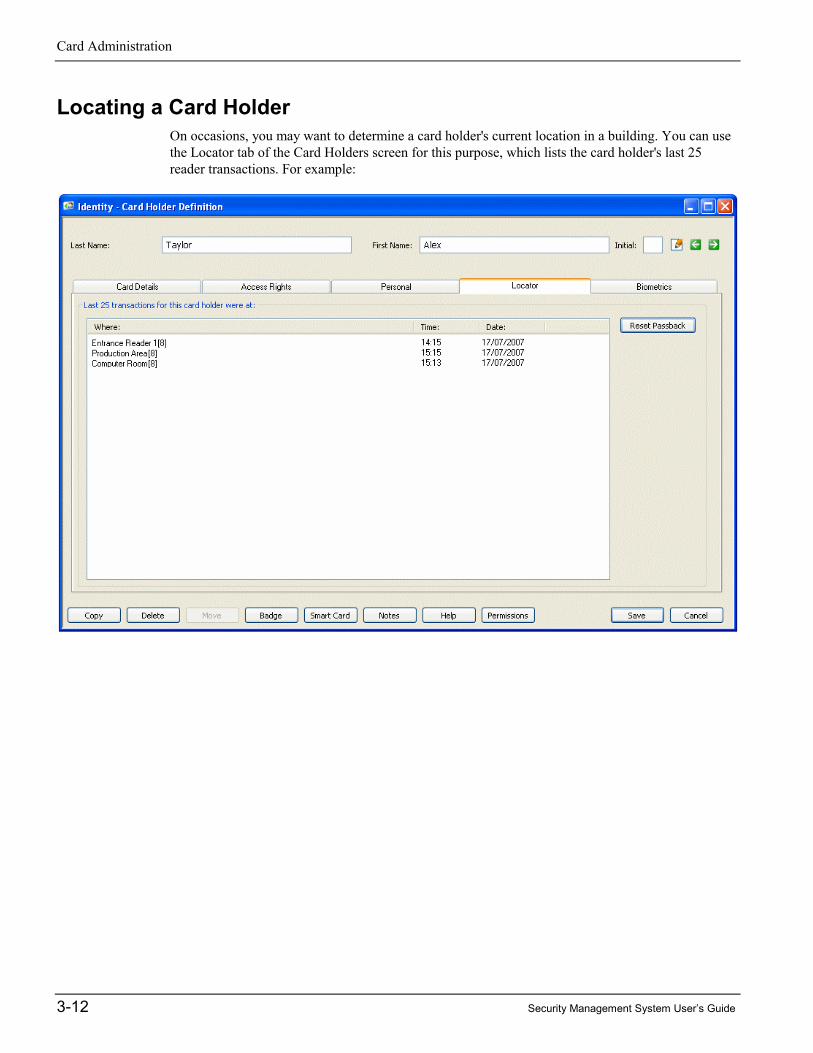
Locating a Card HolderOn occasions, you may want to determine a card holder's current location in a building. You can usethe Locator tab of the Card Holders screen for this purpose, which lists the card holder's last 25reader transactions. For example:

Security Management System User’s Guide 4-1
4 Chapter 4: Producing ID Badges
Introduction
The Security Management Software provides acomprehensive set of tools that allow you to designand print ID badges quickly and easily. A badgemay be used for identification purposes only, or foraccess control, or both.
Producing ID badges is easy. First, you use theTools/Badge Designer screen to create a library ofbadge designs, then the Identity/Card Holdersscreen to select, print and encode a badge for eachperson.
Using the Identity/Card Holders screen, you can quickly enter any information that is required for thebadge, such as the card holder's name and card number. You can also capture the person's picture,signature and any biometric data, then print and encode the card. The user interface has beendesigned to optimize operator efficiency, while allowing full control to include all the graphics andinformation required.
This chapter describes the process of producing badges. An alternative method of becoming familiarwith the process is to use the interactive tutorial, which is available from the Help menu of the SMSsoftware.
Designing BadgesYou can design badges using the Tools/Badge Designer screen. A badge design specifies theappearance of the badge, including the position and type of information to include. For example, abadge design could include the card holder's name, expiry date, company logo and card holder'spicture. The system gives you all the tools you need to create customized badge designs in minutes,with text and graphics applied to both sides of the badge.
Using the Badge Designer, you can create a library of badge designs. You may, for example, decideto create different designs for administration staff, cleaners, contractors and security staff.
A key feature of the Badge Designer is the ability to associate default access rights with each badgedesign for access control purposes. Any card holder allocated a badge design is automatically giventhe badge access rights, which eliminates the need to set up access rights for each person.

Producing ID Badges
4-2 Security Management System User’s Guide
The overall simplicity of the software, supported by context-sensitive help and an interactive tutorial,ensures that anyone with basic mouse/keyboard skills can begin to use the Badge Designer quicklyand efficiently.
Figure 4.1 gives an overview of the key features provided by the Badge Designer.
Figure 4.1: The Badge Designer Definition Screen
Note:• When you open the Badge Designer screen, the menu bar changes to include the options
necessary for designing badges.• Right-clicking an item and selecting Rule enables you to set up a rule that determines whether or
not the item is displayed for a card holder, depending on personal data. For example, you maywant a logo to be displayed only for card holders who belong to a specific department.
You can use the buttons todraw or place downobjects, such as shapes,text and a company logo.
You can use this buttonto toggle betweendesigning side 1 andside 2 of the badge.
You can define the position andsize of the card holder'ssignature and picture, then usethe Identity/Card Holders screento capture this data.
The Database Field tool allows you todefine the position of text that varies foreach card holder, such as the card holder'sname or card expiry date.
Pressing the right-hand mouse key in "whitespace" (or selecting Properties/Side Type)displays a menu that enables you to place achip or magnetic stripe on the current side.
You can associate default accessrights with the badge design.
You can specify an expiryperiod. A badge cannotbe used to gain accessonce expired.

Producing ID Badges
Security Management System User’s Guide 4-3
Producing a Card Holder's BadgeOnce you have produced the badge designs, you can select each card holder's badge from theIdentity/Card Holders screen, as described next
Entering Card Details and Capturing the Card Holder's PictureFirst, you need to make sure that the card holder's details are correct, and to ensure that the cardholder's picture has been captured (assuming that a picture is to be printed on the badge). Use theCard Details tab to do this, as described on page 3-4.
Approving OfficialThe Card Details tab includes an Approving Official option. You can use this to choose the name ofthe person who has authorized the badge to be issued. You can set up approving officials in theAdmin/Approving Official screen:
Capturing the Card Holder's SignatureIf the card holder's signature is to be printed on the card, capture it using the Signature area:
There are three ways of capturing a signature:
� Live – Click this to capture a live picture of the signature from acamera connected to your PC.
� Import – Click this to import a stored picture of the signature (e.g.taken by a digital camera).
� Import Pad – Click this to capture the signature online from asignature pad attached to your computer. The card holder writes thesignature on the pad and the system captures it automatically.
Once you have captured the signature, the icon shown above is replaced by the person's actualsignature.
Producing ID Badges
4-4 Security Management System User’s Guide
Capturing Fingerprint and Hand Geometry DataBiometric recognition is taking an increasingly prominent position as a solution for today's ever-increasing requirement for total security. The Security Management Software uses the latesttechnologies to enable fingerprint and hand geometry to be used as part of access-controltransactions.
Fingerprint and hand geometry biometric data can be captured using the Biometrics tab, making iteasy to set up a card holder's details, capture the biometric data and produce a badge from a singlelocation in the user interface.
After capturing the biometric data, you can use the optional Smart Card Management Module toencode the biometric data onto a smart card, which the card holder presents to a biometric reader togain access. The reader checks the hand or fingerprint data on the card with the actual hand orfingerprint to confirm the person's identity.
Smart-card technology provides the possibility of using a single card for multiple purposes.
For detailed information, please refer to the online help in the SMS software. Alternatively, if you areusing 813 fingerprint readers, you can obtain details of how to enroll fingerprints and use 813 readersfrom the 813 Fingerprint Reader User's Guide.
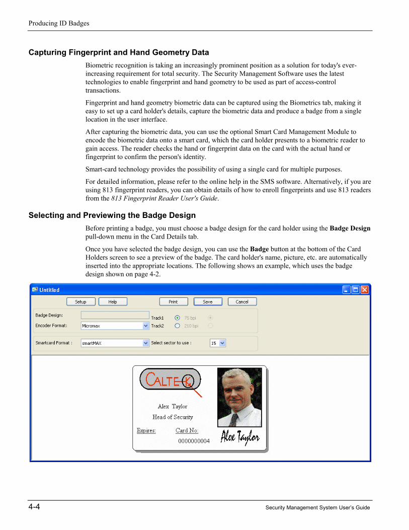
Selecting and Previewing the Badge DesignBefore printing a badge, you must choose a badge design for the card holder using the Badge Designpull-down menu in the Card Details tab.
Once you have selected the badge design, you can use the Badge button at the bottom of the CardHolders screen to see a preview of the badge. The card holder's name, picture, etc. are automaticallyinserted into the appropriate locations. The following shows an example, which uses the badgedesign shown on page 4-2.

Producing ID Badges
Security Management System User’s Guide 4-5
The preview screen contains an Encoder Format option and, if "Smart Card Encoding" option isinstalled, a Smartcard Format option. You can use these to define the format to be used whenencoding the badge.
Printing and Encoding the BadgeIf you wish to print an individual badge, you can simply select Print when viewing the preview ofthe badge, as shown in the previous picture. A suitable combined printer and encoder will print andencode the card in one operation. If smart cards are used, only Philips® MIFARE® formatting issupported from this screen (other formats are supported using the Smart Card button; see page 4-6).
Alternatively, you can save the card holder's details and print several badges in the same print runusing the Identity/Print Badges screen.
If you decide to use the Identity/Print Badges screen, the selection of badge and encoding formatsyou made in the Card Holders screen are treated as defaults, which can be overridden from the PrintBadges screen.
As with other options in the Identity menu, Identity/Print Badges displays a Selection screen, inwhich you select the badges to print. Having done this, the Print Badges screen is displayed, asshown in the following picture. Selecting Print starts the printing/encoding process.
You can override each card holder'sdefault badge and encoding format.
Each person's badge isdisplayed as it is being printed.

Producing ID Badges
4-6 Security Management System User’s Guide
Smart Card ButtonIf the "Smart Card Encoding" cost option is installed, a Smart Card button is available in the CardHolder's screen. Clicking Smart Card displays the following screen, which enables you to encodethe card number and optional biometric data onto the badge if it is a smart card used for accesscontrol:
This screen supports various smart card types, including Philips MIFARE, Philips MIFARE DESfire,HID®, HID iCLASS™, and Texas Instruments™ (ISO 15693). Several different encoders are alsosupported.

Security Management System User’s Guide 5-1
5 Chapter 5: Visitor Management
Setting Up VisitorsThe Visitor Management features of the Security Management Software enable you to improve theefficiency of the visitor check-in process, enhance site security and manage visitor details moreeffectively. The system allows easy entry of visitor details through a dedicated Identity/Visitorsscreen, which can be accessed from any client PC or Web browser (with the Web Access option):
The screen can be used by any authorized employee to enter personal information about their visitorsbefore they arrive on site. This approach can significantly reduce check-in delays, improve efficiencyand enable security staff to verify a person's identity more carefully on arrival.
The Identity/Visitors screen has been designed to enable people who are not normally users of theSecurity Management Software to enter the personal details of their visitors. The Visitors screen issimilar to the Identity/Card Holders screen.

Visitor Management
5-2 Security Management System User’s Guide
It is possible to give different users different levels of access to the Identity/Visitors screen.Some tabs in the screen may not be available, depending on you user privileges (defined inthe Configure/User/Roles screen).
Visitor DetailsThe Visitor Details tab enables you to specify general details of the visitor, such as when the visitor isexpected to arrive and depart, who he/she is visiting, and the name of the escort (if required). In asimilar manner to the Identity/Card Holders screen, you can also capture the visitor's picture, choosea badge design, then print the visitor's badge on a badge printer.
A major benefit of the Visitor Management module is the ability to sign visitors in and out from theVisitor Details tab, using the Sign In and Sign Out buttons. Full details of when the visitor signed inand out are maintained in the History box located near the bottom of the screen.
The current status of the visitor (Pending, Active or Closed) is displayed in a color-coded box nearthe bottom-left corner of the screen, which can instantly show you whether the visitor is still on site.
If Email Notification of Visitor Signing In is selected in the Configure/Preferences/System screen,an email is automatically sent to the card holder when the visitor is signed in. The email address isdefined using a personal data title in the card holder's details. The personal data title must have aCategory of type Email, as defined in the Identity/Personal Data/ Settings/Card Holder screen.
The Visitor Details tab is also able to display a scanned or imported image of the visitor's businesscard. This time-saving feature ensures speedy and accurate acquisition of basic information about avisitor, such as address and contact information, and is of particular benefit in cases when the visitordetails are not entered before the visitor arrives.
Personal DetailsThe Identity/Visitors screen includes a Personal tab, in which you can enter personal details of thevisitor in a similar manner to the Personal tab of the Identity/Card Holders screen (see page 3-11).
The personal data titles (such as "Visitor's Company Name", "Reason for Visit", "Visit ArrangedBy", "Hair Color", etc.) are different from those used for card holders and are set up in theIdentity/Personal Data/Settings/Visitor screen.
Pre-defined data items for each of these personal data titles can be defined in the Identity/PersonalData/List/Visitor Data screen. For example, for the data title "Hair Color", you may want to definedata items such as "Black", "Brown" and "Blonde". You can select pre-defined data items frommenus in the screen.
Visitor Card Details, Access Rights and BiometricsIf the visitor requires an access-control card, you need to specify a card number and other details inthe Card Details tab. You also need to use the Access Rights tab to specify which areas the cardholder can access, and at what times. Setting up card details and access rights for a visitor is similarto setting up the same details for a standard card holder, as described on page 3-4 and 3-6.
If biometric card readers are being used, it may be necessary to capture the visitor's fingerprints orhand geometry before encoding the visitor's access-control card. You can do this using theBiometrics tab, in the same way as for a standard card holder (see page 4-4). If magnetic stripe cards
Visitor Management
Security Management System User’s Guide 5-3
are being used, you can encode the card at the same time it is being printed (assuming you are using acombined badge printer and encoder).
Once a visitor has left the site, it is possible to delete the card number from the visitor's details, thensave the details. This allows the card number to be assigned to another visitor, without deleting theprevious visitor's details, which may be reused if the visitor revisits the site.
Visitor ReportsThe system provides extensive visitor reporting capabilities:
� Identity/Reports/Visitors – You can list details of visitor cards.
� Identity/Reports/Access – You can list details of the access rights of visitor cards.
� View/History/Activity – You can view previous alarms and events generated by visitors.
� View/History/Cardholders Onsite – You can find out which visitors used an entrance reader.
� View/Locator – You can find out the current location of selected visitors.
� View/Muster – The muster (roll call) report includes visitors.
All visitor transactions at access-controlled doors are recorded, and any infringements of site securityare immediately reported.

Visitor Management
5-4 Security Management System User’s Guide

Security Management System User’s Guide 6-1
6 Chapter 6: Digital Video Management
IntroductionThe optional Digital Video Management module provides integration with CCTV and Digital Videosystems. The module enables video images to be viewed, recorded and replayed from easy-to-usescreens within the SMS software.
The Digital Video Management module provides an open platform that supports IP camerasconnected directly to the network, Symmetry EN-9000 Series Video Servers (see page 1-7),Symmetry Network Video Recorders (NVRs) and a wide range of Digital Video Recorders (DVRs),as documented in the Digital Video Design Guide. If required, images can be recorded continuouslyor at scheduled times of the day or night.
A DVR is a device that can record and store images from CCTV cameras. Storing video locally on aDVR avoids the need to transmit video across the network only for recording purposes, and thereforeprevents the system consuming network bandwidth.
This chapter gives an overview of the screens and options available in the Digital Video ManagementModule.
Note: Video Storage Management is used for the recording of video from EN-9000 Series VideoServers and IP cameras (page 6-7).
Summary of Key FeaturesThe following is a summary of key features.
Virtual Matrix Screen:� Simultaneously displays multiple live images from digital video cameras.
� Up to 72 simultaneous live images per PC.
� Includes controls for camera pan, tilt, zoom and focus.
� Instant Record feature.
� Save, print and export images.
� Camera sequencing.
� Camera tours.
� Supports display of Web pages.
� Instant Replay feature.
� Alarm and activity display.

Digital Video Management
6-2 Security Management System User’s Guide
Video Playback screen:� Allows easy replay of video recordings.
� Filter options enable recordings to be located quickly from the database.
� Simultaneous replay of up to four recordings.
� JPEG picture export.
Tagging:� Tagged recordings produced by, for example, a Record Video trigger command or user recording,
are prevented from being overwritten and enable easy playback.
� Also supports tagging by a user-applied "bookmark".
Camera Support:� A wide range of camera types is supported, including Symmetry and Axis IP cameras.
� Maximum number of cameras is license dependent.
CCTV switcher integration:� Cameras attached to legacy CCTV switchers can be viewed, controlled and switched to any
monitor.
� Ancillary devices (such as lamps and wipers) can be switched on or off.
Commands:� Commands can, for example, run scheduled recordings and record incidents automatically (e.g.
from any intrusion or access event).
� Supports commands to switch live video to the virtual matrix.
Playback from alarms or reports:� Incidents recorded automatically by an alarm or event can be easily replayed from history reports
or the View/Alarms screen.
Graphics integration:� Live video can be played from a graphic, such as a plan or map of the building.
Identity Verification:� Operators can compare the live image of a card holder who is using a reader, against the stored
image.

Digital Video Management
Security Management System User’s Guide 6-3
Using the Virtual Matrix ScreenThe View/Digital Video/Virtual Matrix screen enables you to simultaneously view live pictures fromdigital video cameras or Web pages. Each image is displayed in a "cell" located on the right-handside of the screen. Two Virtual Matrix screens can be open at the same time.
To display live images, find the camera or Web page in the tree view, then drag and drop it into acell. You can also drag and drop images from one cell to another. Double-clicking an image displaysthe image in the largest cell.
Note: Black or gray areas in a picture indicate "privacy zones" configured by the installer.
You can change the number ofcells displayed and theirpositions using the ChangeLayout option.
The right-click menu providescontext-sensitive options; forexample, to record video or replaythe last five minutes of video.
Clicking here can display a control to zoom in/out, focus, pan, tilt andfocus the camera, or to move the camera to a preset position. The controlmakes available only those functions the camera supports.
This panel enables you to start camerasequencing, display an image fullscreen, list alarms, view currentactivity and run camera tours.
The tree view contains the digitalvideo cameras set up in the Installscreens, and all Web pages addedusing the Create URL button, whichis located above the tree view.
Once you have decided which cameras and/or Web pages to view, andhave moved each into a cell, you can save the configuration as a"view" using the Save button. The next time you open the screen, youcan select the view from the pull-down menu, which automaticallydisplays the Web pages and camera images in that view.

Digital Video Management
6-4 Security Management System User’s Guide
Using the Video Playback ScreenThe View/Digital Video/Video Playback screen enables you to replay video recordings. Up to fourrecordings can be simultaneously replayed in "cells" located on the right-hand side of the screen. Youcan swap between displaying one and four cells by right-clicking on a cell and selecting/deselectingExpand Cell.
To play a recording:1. In the tree view located near the top-left corner of the screen, select the camera(s) that made the
recording(s).
2. Use the Include pull-down menu to specify the types of video recordings to find from thedatabase. Select All Video if you want to find all recordings.
3. Use the Date and Time panel to specify the date and time range of the recordings to find.
4. Click the Find button. The Results panel lists all recordings that are of the correct type andinclude any part of the time period specified by the From and To fields.
5. Drag and drop any recording listed in the Results panel into a cell, or double-click. Playbackstarts from the Start time shown in the Results panel.
You can changeplayback speed, orpause and play therecording.
The time line shows periods during which recordings exist for thecurrently selected cell, and your current position in the recording. Youcan drag and drop the marker to replay from a different time. Thedifferent colors in the time line indicate different types of recording, e.g.bookmarked recordings, or recordings started by an alarm condition.
You can use these options to performactions such as saving the recording as anAVI movie, zooming in or out of the timeline and bookmarking periods of interest.
This lists therecordingsavailable for theselected cameras.

Digital Video Management
Security Management System User’s Guide 6-5
Identity VerificationThe Identity/Identity Verification screen displays live video from all cameras in a selected identityverification group, as set up in the Admin/Group/Identity Verification screen. Cameras connecteddirectly to the PC can be used (such as a webcams). If Digital Video Management is installed, digitalvideo cameras can also be used.
An identity verification group can contain up to four cameras, and each camera has an associatedreader. For example, the "Front Door" reader may be associated with the "Front Door" camera. Whenthere is a transaction from a known card at an associated reader, the stored image of the card holderor visitor is displayed next to the live image. This enables a guard to compare the two images toverify the person's identity. For example:
If there is an invalid transaction (such as At Wrong Door), the card holder's stored image is outlinedwith a flashing red border.
The field below the pictures displays information about the transaction made at the reader, suchwhether access was granted, the card number (in square brackets) and the date and time of thetransaction. The remaining three fields provide additional information, such as the person's full name,line manager and card expiry date. The information displayed is specified the Configure/IdentityVerification screen.
If necessary, the system can be set up in "PC Door Control mode", which requires the guard to selectGrant Access ( ) or Deny Access ( ) for each transaction.
If only one camera is used and Rotate in 2 x 2 View is selected in the Admin/Group/IdentityVerification screen, the screen displays the last four verification transactions, with the associatedimages.
It is possible to have a camera selection of None in the Admin/Group/Identity Verification screen. Inthis case, the stored image and transaction details are displayed in the Identity/Identity Verificationscreen, with no live image.

Digital Video Management
6-6 Security Management System User’s Guide
Using the Find ButtonThe Find button ( ) is useful in cases where a person who does not have their access card hasasked for access. Clicking the button displays a card selection screen, which allows the name of thecard holder to be selected:
Clicking Open displays the card holder's stored image and details:
If required, you can use the green buttons to select the previous/next card holder. Clicking OKinserts the card holder's picture and details into the Video Verification screen, where access can beaccepted or denied.

Digital Video Management
Security Management System User’s Guide 6-7
Video Storage Management ModuleThe optional Video Storage Management Module is used to create Symmetry NVRs, which storevideo from IP cameras or Symmetry EN-9000 Series Video Servers to a network storage device.
The system can be set up with one or more Symmetry NVRs. A Symmetry NVR is provided "asstandard" on the database server when the Digital Video Management software is installed. Ifrequired, licenses for additional Symmetry NVRs can be purchased.
Configuration of data storage is set up using the Configure/Digital Video/Network Video Recorderscreen, as shown below.
Multiple storage locations can be set up to store videofrom each device. If the location at the top of the listbecomes full, the next location is used.
You can set up schedules that automatically purge recordings fromthe storage device that are older than a specified number of days.Different purge settings can be defined for different types ofrecordings (e.g. tagged video can be purged less often).

Digital Video Management
6-8 Security Management System User’s Guide
Using CCTV Switchers and CamerasA CCTV switcher is a device that can be connected to a serial port of an SMS client PC. Theswitcher unit has connections for cameras and monitors, and is able to switch live video from anyconnected camera to any connected monitor. A CCTV switcher is also able to switch ancillarydevices, such as camera lamps and wipers, on or off.
You can switch video to a selected monitor, control camera position and switch ancillary devices onor off using the View/CCTV Cameras screen, as shown below. Alternatively, commands can be setup to perform the actions automatically at scheduled times or in response to alarms or events.
Viewing a CCTV Image During Alarm AcknowledgementA Command button is provided in the Alarm Acknowledgement screen, which can be used to switchthe CCTV camera at the alarm location to a pre-defined monitor. This enables the operator to viewthe images at the alarm location quickly and easily. You can set up the command activated by theCommand button using the Admin/Alarm/Commands screen.
You can use the buttons to controlthe camera's pan/tilt, zoom andfocus, and to move it to a presetposition (camera type permitting).
If a switcher has a separate hardwiredvideo connection to the PC, thepictures displayed at the CCTVmonitor are also displayed here.
These shows the name of the camera andmonitor selected in the Selection screen.Pictures from the camera areautomatically switched to the monitor.
These buttons switchthe camera's ancillarydevices on or off.
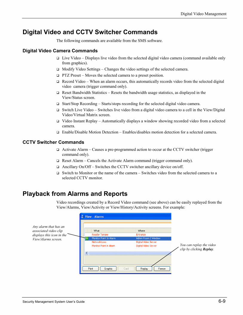
Digital Video Management
Security Management System User’s Guide 6-9
Digital Video and CCTV Switcher CommandsThe following commands are available from the SMS software.
Digital Video Camera Commands� Live Video – Displays live video from the selected digital video camera (command available only
from graphics).� Modify Video Settings – Changes the video settings of the selected camera.� PTZ Preset – Moves the selected camera to a preset position.� Record Video – When an alarm occurs, this automatically records video from the selected digital
video camera (trigger command only).� Reset Bandwidth Statistics – Resets the bandwidth usage statistics, as displayed in the
View/Status screen.� Start/Stop Recording – Starts/stops recording for the selected digital video camera.� Switch Live Video – Switches live video from a digital video camera to a cell in the View/Digital
Video/Virtual Matrix screen.� Video Instant Replay – Automatically displays a window showing recorded video from a selected
camera.� Enable/Disable Motion Detection – Enables/disables motion detection for a selected camera.
CCTV Switcher Commands� Activate Alarm – Causes a pre-programmed action to occur at the CCTV switcher (trigger
command only).� Reset Alarm – Cancels the Activate Alarm command (trigger command only).� Ancillary On/Off – Switches the CCTV switcher ancillary device on/off.� Switch to Monitor or the name of the camera – Switches video from the selected camera to a
selected CCTV monitor.
Playback from Alarms and ReportsVideo recordings created by a Record Video command (see above) can be easily replayed from theView/Alarms, View/Activity or View/History/Activity screens. For example:
You can replay the videoclip by clicking Replay.
Any alarm that has anassociated video clipdisplays this icon in theView/Alarms screen.
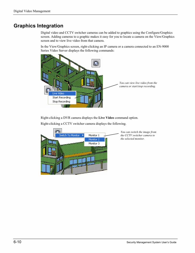
Digital Video Management
6-10 Security Management System User’s Guide
Graphics IntegrationDigital video and CCTV switcher cameras can be added to graphics using the Configure/Graphicsscreen. Adding cameras to a graphic makes it easy for you to locate a camera on the View/Graphicsscreen and to view live video from that camera.
In the View/Graphics screen, right-clicking an IP camera or a camera connected to an EN-9000Series Video Server displays the following commands:
Right-clicking a DVR camera displays the Live Video command option.
Right-clicking a CCTV switcher camera displays the following.
You can view live video from thecamera or start/stop recording.
You can switch the image fromthe CCTV switcher camera tothe selected monitor.

Security Management System User’s Guide 7-1
7 Chapter 7: Alarms Monitoring
Understanding Alarms MonitoringEach major action that takes place at devices such as readers and monitor points is classed as eitheran event or alarm. Events are non-serious conditions and are simply logged for future reporting.Alarms, however, (such as "Door Forced") are potentially serious violations of security and arealways displayed in the Alarms screen, which forms the central part of the system's alarmsmonitoring capabilities.
It essential that the user who is tasked with alarms monitoring is either logged into theSecurity Management Software or has the Login screen displayed. The system should havebeen set up so that no other scenario is possible.
How New Alarms are SignaledWhen a new alarm occurs, the PC that is receiving the alarms makes a sound, which can be set up tovary depending on the alarm type and location of the alarm. If the Login screen is displayed, alarmdetails are shown in a box in the bottom-left corner of the dialog:
The box shows:
� The number of new alarms, i.e. the number of alarms that you have not yet acknowledged. Youwill find out how to acknowledge an alarm later in this section.
� The total number of alarms.
� The priority of the highest-priority new alarm (1 is the highest priority, 999 is the lowest).
If you are logged in, this information is shown at the bottom of the display area, together with aSilence button to stop the sound:
When there is a new alarm, you will see a flashing blue light in the Windows System Tray. Thischanges to a picture of a card after all alarms have been acknowledged. In addition, you may see"Alarm!" in the background of the Security Management Window (depending on client preferences).
If your system has been set up for real-time printing, details of the alarm are automatically printed. Itis normal to use an impact printer that has continuous stationery for this purpose.

Alarms Monitoring
7-2 Security Management System User’s Guide
Your system can also be set up to display a graphic of the alarm location or to send an email to anominated person.
The Steps to Take When an Alarm OccursWhen an alarm occurs, carry out the following steps:
1. View the details of the new alarm in the View/Alarms screen.
2. If graphics have been set up, view the location of the alarm (this may be displayed automatically).
3. Acknowledge the alarm to determine what instructions to follow, e.g. the instruction may be to"Contact Patrol Guard to Investigate Cause".
4. Reset the alarm.
5. Clear the alarm from the Alarms screen.
All of the actions you take are recorded for future reporting. The above steps are described in moredetail in the following sections.
Viewing the Details of an AlarmWhen a new alarm occurs, the first action to take is to open the Alarms screen from the View menu,if it is not already open. The Alarms screen gives details of all alarms that have not yet been cleared;for example:

Alarms Monitoring
Security Management System User’s Guide 7-3
All new alarms are, by default, shown in red and in order of priority. The card number (if known) isshown in square brackets. Alarms change color from red to blue or green as you go through thevarious steps of dealing with the alarm; we'll describe the meaning of blue and green shortly.
Details of each alarm are given, including who caused the alarm (if known from the card used), thealarm message and the location.
Optionally (and providing a Dedicated Micros DVR is not being used), the lower half of the screendisplays a pie chart of outstanding alarms, an alarm statistics panel and a bar chart that shows whenalarms were received. You can change the viewing angle of a chart by clicking on the picture andmoving the mouse.
Ideally, you should keep the Alarms screen displayed at all times, since it allows you to read thedetails of new alarms as soon as they occur.
Setting Up Alarm FiltersClicking the Filters button in the Alarms screen displays the following screen, which enables you todefine one or more alarm filters:
Each filter you define creates an extra tab in the Alarms screen. The tab displays only those alarmsthat the filter is set up to display. Each SMS client can display different alarm filters.
Alarm filters provide a method of partitioning the viewing of alarms in the Alarms screen. You can,for example, create an alarm filters to display only alarms of a specified type or from a specifiedlocation, or combinations of different alarm types.
The panel near the bottom of the screen shows how the currently selected alarms filter is set up. Inthis example, the "Assembly Area" filter will display alarms from the assembly area reader or fromthe assembly area window monitor point.

Alarms Monitoring
7-4 Security Management System User’s Guide
Viewing a Graphic of the Alarm's LocationIf graphics have been defined for your installation, clicking on an alarm, then selecting the Graphicbutton displays a graphic of the alarm's location.
Graphics can also be accessed at any time by selecting the Graphics option in the View menu, orthey can be set up (in the Configure/Preferences/Client screen) to be displayed automatically.
Acknowledging an AlarmAs soon as possible after a new alarm occurs, you should acknowledge it by using the AcknowledgeAlarms screen, as shown in the following picture. The screen can be displayed by double-clicking onthe alarm in the Alarms screen, or if a graphic is being viewed, by selecting the Acknowledge buttonfrom the Graphics screen.
The Acknowledge Alarms screen displays the instructions that you should follow (in this case,"SEND GUARD TO INVESTIGATE"). The instructions are specific to the type of alarm and are setup using the Admin/Alarm/Instructions and Admin/Alarm/Definitions screens.
The Acknowledge Alarms screen also provides a Comments box in which you can record the actionstaken. You add a comment either by typing text in the box or by selecting the Select StandardComment button and choosing one of the predefined comments. Predefined alarm comments are setup by an administrator using the Admin/Alarm/Comments screen.
Selecting OK acknowledges the alarm and redisplays the Alarms screen, which now shows the alarmin blue (alarm acknowledged, but device not reset) or green (alarm ready to be cleared). These statesare described in the sections that follow.
If required, you can return to the Acknowledge Alarms screen to add more comments by reselectingthe alarm in the Alarms screen. Your previous comments are shown in the Previous Comments box,as shown in the following picture.

Alarms Monitoring
Security Management System User’s Guide 7-5
Each comment in the Previous Comments box is prefixed with the name of the user who added thecomment and the time that the comment was added.
The Command button (to the right of Select Standard Comment) is ungrayed if a command hasbeen set up for the alarm in the Admin/Alarm/Commands screen. Selecting the button sends thecommand. The command may, for example, cause the CCTV image at the alarm location to bedisplayed on a CCTV monitor, which allows you to see the person who caused the alarm.
Resetting the AlarmIf the whole alarm message, or just the time and date, are shown in blue in the Alarms screen, itindicates that you have acknowledged the alarm, but the physical device has not been reset. Forexample, a fire exit that has a monitor point has not been closed. The device must be reset before youcan clear it from the Alarms screen.
Some alarms, such as card alarms, do not have a 'blue' status.
Clearing the AlarmIf the whole alarm message, or just the time and date, are shown in green in the Alarms screen, itindicates that you have acknowledged the alarm and if necessary reset it, but have not yet cleared itfrom the screen.
The alarm can be cleared by selecting the alarm (which displays the Acknowledge Alarm screen),followed by the Clear button. You may also want to add a comment before selecting Clear, such as"Supervisor Notified".

Alarms Monitoring
7-6 Security Management System User’s Guide

Security Management System User’s Guide 8-1
8 Chapter 8: Producing Reports
IntroductionThe reporting features within the Security Management Software enable comprehensive listings ofalarms, events, user actions, access rights, configuration settings and other information to beproduced, giving full traceability of all essential information.
It's easy to produce a wide range of different types of report. You can, for example, produce reportsof the card holders who have been granted access through specified doors, the people who haveattempted to gain entry into unauthorized areas, and the actions taken to acknowledge alarms.
Using the reports provided, you can quickly find the information you need. The extensive filteringoptions ensure that the reports display only the information you require, leading to improved clarityand ease of use.
For added flexibility, the system enables a library of customized reports to be defined, which canprinted automatically at scheduled intervals. For ultimate customization of report format and content,integration with the popular Crystal Reports® software is provided.
The reporting system is essential for any manager who needs to be assured that attempted breaches ofsecurity or other incidents can be investigated properly and quickly, or who requires comprehensivepaper records of how the system has been configured.
Activity ReportsActivity reports are accessible from the View menu at nominated client machines (as set up in theInstall/Clients screen) and are displayed on the screen. The View/ Activity report displays all alarmsand events as they occur, and has a History button that displays on a day-by-day basis any alarmsand events that have been recorded in the system's log. For example:
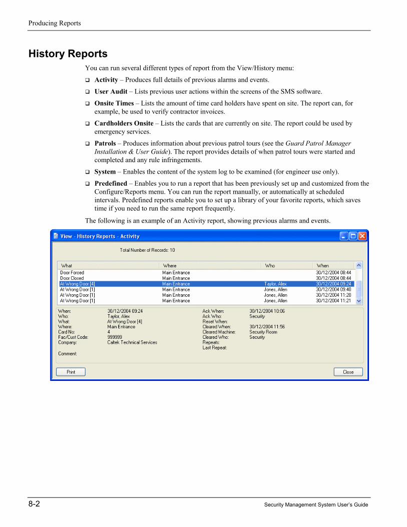
Producing Reports
8-2 Security Management System User’s Guide
History ReportsYou can run several different types of report from the View/History menu:
� Activity – Produces full details of previous alarms and events.
� User Audit – Lists previous user actions within the screens of the SMS software.
� Onsite Times – Lists the amount of time card holders have spent on site. The report can, forexample, be used to verify contractor invoices.
� Cardholders Onsite – Lists the cards that are currently on site. The report could be used byemergency services.
� Patrols – Produces information about previous patrol tours (see the Guard Patrol ManagerInstallation & User Guide). The report provides details of when patrol tours were started andcompleted and any rule infringements.
� System – Enables the content of the system log to be examined (for engineer use only).
� Predefined – Enables you to run a report that has been previously set up and customized from theConfigure/Reports menu. You can run the report manually, or automatically at scheduledintervals. Predefined reports enable you to set up a library of your favorite reports, which savestime if you need to run the same report frequently.
The following is an example of an Activity report, showing previous alarms and events.

Producing Reports
Security Management System User’s Guide 8-3
Locator ReportsThere are two types of locator report. The first is actually a tab of the Card Holders or Visitorsscreen, rather than a true report. It lists the card holder's last 25 transactions (see page 3-11).
The second is accessible from the View menu and shows, for each selected card holder, the name ofthe reader that last granted access. This can help you to determine the current location of one or morecard holders. For example:
Card ReportsThe Identity/Reports/Cards screen enables you to produce a report that lists how selected cardholders have been set up in the Card Holders screen:

Producing Reports
8-4 Security Management System User’s Guide
Access ReportsYou can use the Identity/Reports/Access screen to produce reports of access rights:
Using the Filter By pull-down list, you can, for example, produce reports of:
� Cards using a specified time code.
� Cards using a specified reader, floor or output group.
� Cards that can use a specified door.
� Doors that can be accessed by a specified card.
� Cards that are to expire between specified dates.
� Cards unused for a specified number of days.
The reports can include or exclude inactive cards and visitor cards.
Visitor ReportsThe Identity/Reports/Visitors report produces a list of current, previous and future visitors. You may,for example, want to use this report to find out the names of all the visitors expected on a specifieddate.

Producing Reports
Security Management System User’s Guide 8-5
Configuration ReportsYou can use the Tools/Configuration/Reports screen to produce a large number of different reports toview how readers, holidays, time codes, users, commands, etc. have been set up. For example:
You can also use Tools/Configuration/View to display a tree view of how your system is set up, asshown in the following picture.

Producing Reports
8-6 Security Management System User’s Guide
Muster (Roll Call) ReportsA muster report (available only with the "Safety Roll Call Management Module") shows a list ofpeople who are recorded by the Security Management Software as being in the building, togetherwith details of the last reader they used. It is intended to be used during fire or other emergencies toassist the rescue services. The following is an example of a muster report:
Muster reports can be produced automatically when a monitor point triggers, such as an output of afire alarm. You can also produce then manually using the View/Muster screen.
Muster Report ConfigurationThe muster report must first be set up using the Configure/Muster screen:
You can choose to order thecard holders in the reportby name or card number.
You can organize the reportinto separate sections (e.g. bydepartment).
A person is included in thereport only if the last readerused is an on-site reader.
A card holder is removed from amuster report when he or sheperforms a transaction at amuster reader.
The report can be startedautomatically when a monitor pointsuch as a fire alarm triggers (AutoStart), or manually from theView/Muster screen (Manual Start).
The report repeats itself automaticallyuntil there is no-one left in the buildingor until you reset it.
The delay should be set to givemost people enough time to reacha muster reader.
You can send the report to morethan one location.
This prevents the first report beingproduced until there are fewer thana specified number of people left tomuster.
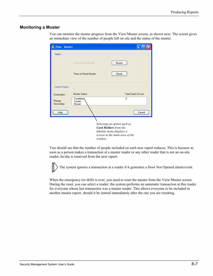
Producing Reports
Security Management System User’s Guide 8-7
Monitoring a MusterYou can monitor the muster progress from the View/Muster screen, as shown next. The screen givesan immediate view of the number of people left on site and the status of the muster.
You should see that the number of people included on each new report reduces. This is because assoon as a person makes a transaction at a muster reader or any other reader that is not an on-sitereader, he/she is removed from the next report.
The system ignores a transaction at a reader if it generates a Door Not Opened alarm/event.
When the emergency (or drill) is over, you need to reset the muster from the View/Muster screen.During the reset, you can select a reader; the system performs an automatic transaction at this readerfor everyone whose last transaction was a muster reader. This allows everyone to be included inanother muster report, should it be started immediately after the one you are resetting.
Selecting an option such asCard Holders from theIdentity menu displays ascreen in the main area of thewindow.

Producing Reports
8-8 Security Management System User’s Guide

Security Management System User’s Guide 9-1
9 Chapter 9: Other Features
This chapter describes other key miscellaneous features of the Security Management Software.
Setting Up User Roles and AccountsA user is a person who uses the Security Management Software on the PC. There are two stages tosetting up users:
1. Use the Configure/User/Roles screen to define one or more user roles. Each role (e.g. SystemManager) specifies a set of permissions to the screens of the Security Management Software.
2. Use the Configure/User/Accounts screen to create the user's account, which specifies the user'slogin name, password and role.
Setting Up RolesRoles are set up in the Configure/User/Roles screen:
A role defines a set of access privileges to the screens of the Security Management Software. Aseries of roles can be set up for different categories of user. In the example shown above, the role has

Other Features
9-2 Security Management System User’s Guide
been named "Security Guard", which could be assigned to any user who needs to perform guard tasksin the Security Management Software.
Each role provides four levels of access to each screen: View (orange), Modify (blue), Delete (green)and None (red). If, for example, you set the access to a screen to be view only, users who belong tothe role will be able to view the contents of the screen, but nothing else. Modify access allows usersto alter the information in the screen, and Delete access enables users to delete complete records,such as a card holder definition.
Roles enable the range of tasks to be carried out by each type of user to be restricted, which not onlyenhances system security, but also simplifies the user interface, since the system displays menuoptions for only those screens that a user has access to. Roles make it easy to set up the privileges ofnew users or modify the privileges of existing users.
As with most computer systems that offer these types of security arrangements, only one user shouldhave full access to all options (and, if applicable, to every company's information).
Creating User AccountsYou can create a user's login name and password, and assign the user to a role using theConfigure/User/Accounts screen:
A simple selection of the role (in the User Role menu) instantly sets up the user's required privileges.
The Secure Logon options enable logons to be accepted only after a user has presented a smart cardor fingerprint at an appropriate reader. The Cardholder Fingerprint Enrollment Options are usedwhen enrolling fingerprints in the Identity/Card Holders or Identity/Visitors screen.
If different SMS language packs areinstalled, you can choose thelanguage to use for the user. Whenthe user logs in, menus and optionswill be displayed in the specifiedlanguage.

Other Features
Security Management System User’s Guide 9-3
Sending CommandsThe ability to send commands is an extremely powerful feature of the Security Management System,which enables you to change the status and mode of operation of devices such as readers, monitorpoints, auxiliary outputs and cameras.
There are three types of commands:
� Manual Commands – These enable you to change the status or mode of operation of a deviceimmediately. For example, you can send a manual command to release a door's lock, or to switcha reader from card-only mode to card-and-PIN mode.
� Scheduled Commands – These cause commands to be executed at pre-defined times each day.For example, you could set up a scheduled command to switch on CCTV recording at the sametime each day.
� Trigger Commands – A trigger command is executed only when a defined action takes place.For example, a CCTV camera could be switched to a specified SMS client when an alarm sensoris triggered, or doors can be unlocked on a fire alarm. Trigger commands are also known asconditional or "If, Then, When" commands.
The following sections explain the different types of command in more detail.
A time-saving feature is the ability to send a single command to a group of monitor points,readers or auxiliary outputs (created using the options in the Admin/Group menu). Thecommand is then executed at all devices in the group.
Manual Commands (Command Center)
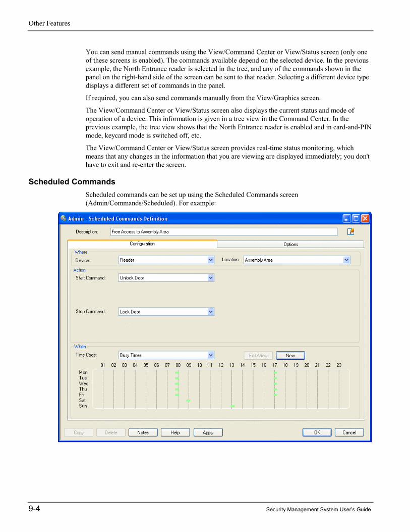
Other Features
9-4 Security Management System User’s Guide
You can send manual commands using the View/Command Center or View/Status screen (only oneof these screens is enabled). The commands available depend on the selected device. In the previousexample, the North Entrance reader is selected in the tree, and any of the commands shown in thepanel on the right-hand side of the screen can be sent to that reader. Selecting a different device typedisplays a different set of commands in the panel.
If required, you can also send commands manually from the View/Graphics screen.
The View/Command Center or View/Status screen also displays the current status and mode ofoperation of a device. This information is given in a tree view in the Command Center. In theprevious example, the tree view shows that the North Entrance reader is enabled and in card-and-PINmode, keycard mode is switched off, etc.
The View/Command Center or View/Status screen provides real-time status monitoring, whichmeans that any changes in the information that you are viewing are displayed immediately; you don'thave to exit and re-enter the screen.
Scheduled CommandsScheduled commands can be set up using the Scheduled Commands screen(Admin/Commands/Scheduled). For example:

Other Features
Security Management System User’s Guide 9-5
Scheduled commands consist of a pair of commands and a time code. You nominate one of thecommands as a start command and the other as a stop command. The start command is then executedat each start time in the time code, and the stop command is executed at each stop time.
Consider the following example, which reflects the scheduled command set up in the previouspicture:
Time code ("Busy Times"):
07:45 to 08:05 Monday to Friday
16:55 to 17:15 Monday to Friday
08:45 to 09:05 Saturday only
12:55 to 13:15 Sunday only
Start command: Unlock Door
Stop command: Lock Door
This example shows a scheduled command that could be used to unlock and re-lock the main door tothe Assembly Area at busy times of the day. The start command is Unlock Door, which enablespeople to gain access without having to use their cards. The command is executed at 07:45 and 16:55Monday to Friday, 08:45 on Saturdays and 12:55 on Sundays.
The stop command is Lock Door, which means that after the command, people gain access in thenormal way; that is, by presenting a card to the reader. The command is executed at 08:05 and 17:15Monday to Friday, 09:05 on Saturdays and 13:15 on Sundays.
It is normal, although not compulsory, for the start and stop commands to have opposite effects.
Scheduled commands can also be useful to switch readers into different modes. For example, as anadded security measure, you may want to switch readers into card-and-PIN mode during the night.
You can also enable and disable a monitor point or a group of monitor points, which may be useful ifpeople want to open, for example, monitored fire exits during the day.
An auxiliary output or a group of auxiliary outputs can also be switched on or off according to timeof day, which may be appropriate for external lights or other devices.
Trigger CommandsScheduled commands bring a great deal of flexibility to your Security Management System, but evenmore flexibility is achieved through the use of trigger commands (otherwise known as conditionalcommands), as set up in the Admin/Commands/Trigger screen. The following picture shows anexample of a trigger command, which is generated when the "Workshop Fire Exit" monitor point isin the alarm state.

Other Features
9-6 Security Management System User’s Guide
A trigger command is executed if a specified alarm/event message is generated from a specifieddevice/card between a start and stop time of a specified time code. This becomes clear from a simpleexample! Consider the trigger command set up in the previous picture:
Device name: Workshop Fire Exit (a monitor point)
Alarm/event message: Monitor Point in Alarm
Command to: Main Siren (an auxiliary output)
Command: Output On
Time code: Always
In this example, if the Workshop Fire Exit monitor point generates the alarm/event "Monitor Point inAlarm" at any time, then the Main Siren is switched on.
In this case, the command is triggered as a result of an alarm/event from a monitor point, but you canalso trigger commands from, for example, a reader or card alarm/event. If you choose a monitorgroup or reader group, the command is triggered if any device in the group generates the selectedalarm/event.

Other Features
Security Management System User’s Guide 9-7
Threat Level ManagementThe optional Threat Level Manager features of the Security Management System enable you tochange a building's security at the click of a button. You can enhance security when there is a greaterthreat of criminal or terrorist activities, or during times of limited occupancy such as holiday or siteshutdown periods, and lower it at other times. Five threat levels are available, each of which you cancustomize using the Configure/Threat Levels screen to provide a different level of security:
Changing the threat level (in the Admin/Change Threat Level screen) can determine which cardshave access, which areas they can access and the scheduled and trigger commands that can operate.For further information, please read the Threat Level Manager Installation and User Guide.
Guard Patrol ManagementThe Guard Patrol Manager is an optional module for configuring, recording and reviewing guardpatrols. The module includes a complete set of tools for setting up and managing patrols entirelyfrom the SMS software. It benefits from the ability to use access-control readers as tour checkpoints,resulting in the need for no specialist hardware or data-collection devices, and making theintroduction of patrol management both cost-effective and easy to implement.
Patrols can be set up to specify the sequence of checkpoints to visit and the time allowed for theguard to travel between them.

Other Features
9-8 Security Management System User’s Guide
The progress of a patrol can be monitored, and previous patrols reviewed in reports. Of particularbenefit in high-security applications is the ability for the system to notify SMS operators immediatelyof any rule infringements, such as missed checkpoints or late arrival.
The module also provides an interface to the popular GCS® TopGuard® software. TopGuard makesit easy to check a wide range of items, such as windows, fire extinguishers and keys, and for theguard to record any incidents during a tour. Simply presenting a data-collection device such as aProxiPen® to a small tag records the visit or incident. The interface automatically transfers all visitedcheckpoints and any recorded incidents to the SMS software for centralized reporting and alarmhandling.
For further information, please read the Guard Patrol Manager Installation and User Guide.
Graphics ManagementThe View/Graphics screen enables devices such as readers, doors, CCTV cameras and sensors to beeasily monitored, located and controlled from graphics. A graphic, could, for example, be a map orplan of the building.
Graphics can show the current alarm status of any device being monitored. If the graphic is a map,this makes it easy to determine the location of an alarm and to send personnel quickly to an incident,leading to improved site security and efficiency.
Graphics, which are installed in the Install/Graphics screen and configured in the Configure/Graphicsscreen, can contain links to other graphics, enabling an operator to locate an alarm or device withincreasing accuracy. To make response times even quicker, a graphic can be set up to be displayedautomatically when an alarm occurs.
Graphics also allow an operator to control devices. For example, an operator can grant accessthrough a selected door, connect to an intercom or switch a CCTV camera to a specified monitor.
Graphics provide an easy-to-use interface for monitoring and controlling the security managementsystem. The simplicity and intuitive interface enables personnel to obtain the benefits of usinggraphics with minimal previous knowledge.

Other Features
Security Management System User’s Guide 9-9
Web AccessThe optional Web Access module enables you to monitor, control and administer your SecurityManagement System using Microsoft Internet Explorer or the Citrix Program Neighborhood softwareover the Internet or through your company's intranet.
Using the Web Access module, you have the ability to perform a wide range of tasks, such as settingup card holders, producing badges, generating reports, viewing digital video, monitoring alarms andregistering visitor details. A Web Client requires no sentinel or special software to be installed,making it the ideal choice for users who require casual access to the SMS software from any location.
Server
Web Client
Web Client
Internet
The user interface at a Web Client is the same as is displayed at a standard client of the SMSsoftware. This enables users to obtain the full benefits from the easy-to-use software and eliminatesthe overhead of learning a new user interface.
Reader ModesReaders are, of course, a key element of your Security Management System and their behavior mustbe matched to your site's specific requirements.
Readers can be switched into several different modes, as described next.
Card-and-PIN ModeBy using commands, you can switch any reader that has a keypad between card-only and card-and-PIN mode. When a reader is in card-only mode, there is no need to enter a PIN to gain access. Withcard-and-PIN mode, a PIN has to be entered, unless the card holder has executive card privileges, asset up in the Card Holders screen.
It may be a good idea to switch to card-only mode at busy times of the day by using a scheduledcommand.
User-Code ModeUser-code mode can be used by keypad readers. When a reader has been enabled for user-codemode, card holders are able to gain entry without their card by:
1. Pressing the # key.
2. Entering the card number (no need to enter leading zeroes).
3. Pressing the * key.
There is no need to present the card to the reader (although the use of a card will be accepted in thenormal way).

Other Features
9-10 Security Management System User’s Guide
You can enable user-code mode by sending the User Code Only or User Code + PIN command to thereader. User Code + PIN forces card holders to enter a PIN as well as the card number while thereader is enabled for user-code mode.
You can disable user-code mode by sending the User Code Disable command to the reader.
Card-Command ModeCard-command mode enables a card holder who has the Command Card Holder option set in theIdentity/Card Holders screen to generate card command messages at keypad readers. The messagescan be made use of by trigger commands, for example to arm or disarm intruder-alarm systems,switch lights on or off, or to change the card PIN or door open time.
In order to allow the card holder to generate a card-command, the reader must have been enabled forthe mode by sending the Card Command Mode On command to the reader. You can disable card-command mode by sending the Card Command Mode Off command.
Keycard ModeA keycard holder can switch a reader between keycard-in and keycard-out states (access rightspermitting) by presenting his or her card, followed by a four-digit PIN in a special sequence; thisbeing 3412 for a PIN of 1234. When a reader is in keycard-out state, all cards except keycards aredenied access, irrespective of access rights. When a card reader is in keycard-in state, normaloperation is resumed. Keycard mode can be useful in cases where, for example, an intruder alarmneeds to be armed and disarmed manually only by authorized personnel.
The reader must be keycard enabled in the Install/Access Control/Reader screen and any person whoneeds to be a keycard holder must have the privilege selected in the Identity/Card Holders screen.
You can enable or disable keycard mode by sending the Keycard Mode On or Keycard Mode Offcommand to the reader. You can set the keycard-in or keycard-out modes by using the Keycard In orKeycard Out command.
Customer Code Only ModeThis mode allows access to any card encoded with a valid customer code, as configured in theFacility/Customer Codes screen in the Configure menu. When in this mode, a card's access rights areoverruled. Refer to the View/Command Center Online Help for further details.
Customer Code Only No Store ModeThis mode operates in the same manner as Customer Code Only mode, except that a record of eachtransaction will not be stored.
Enabled/Disabled ModeThe Disable Reader and Enable Reader commands enable you to disable and enable a readerrespectively. Disabling a reader stops people from being able to use it.
Fingerprint ModeFingerprint readers can be set up to require just one fingerprint or two fingerprints using the SingleFingerprint Mode and Two Fingerprint Mode commands. You can disable the requirement to presenta fingerprint using the Disable Fingerprint Mode command.

Other Features
Security Management System User’s Guide 9-11
Duress ModeA card holder can also use the PIN to create a "duress" alarm/event by preceding the PIN with a zeroand not entering the last digit. A duress alarm/event signals that the card holder is gaining accessunder duress. Duress mode can only be used at readers that have been duress enabled in theInstall/Access Control/Reader screen.
Delete-on-PIN-Error ModeIf a card holder enters an incorrect PIN, the "Wrong PIN" alarm/event is generated. The system canbe set up to prevent the card from being used if the PIN is entered incorrectly a specified number oftimes. The system or node (depending on the Delete PIN Errors Globally preference) will no longeraccept the card and the "Deleted for PIN" alarm/event is generated.
Toggle ModeIf a reader is enabled for toggle mode in the Install/Access Control/Reader screen, each valid access-control transaction or each valid exit request (from an exit-request switch) causes the door to togglebetween being permanently locked and permanently unlocked.
As an example, the mode could be used for an entrance that is constantly manned by a guardthroughout the day. In the morning, the guard could use his or her card to unlock the doorpermanently, then monitor everyone entering the building. To lock the door permanently, the guardcould simply perform a normal access-control transaction on the way out.
Two-Card ModeIf a reader has been enabled for two-card mode in the Install/Access Control/Reader screen, two validaccess transactions from two different cards must be made at the reader before access is granted. Thetransactions must be made within a specified period of time.
This mode is used in areas of a building where it is important that more than one person is present.
Reader-Inhibit ModeThis mode is typically used for readers that control turnstiles. If a reader is enabled for reader-inhibitmode in the Install/Access Control/Reader screen, when a card holder is granted access, the reader iseffectively disabled until the card holder has passed through the turnstile and it has re-locked.
Antipassback ModesA reader can be switched into various antipassback modes. Please refer to the Online Help for furtherinformation.
Backing Up and ArchivingA backup, which can be produced using the Tools/Backup screen, is a copy of the data in the SMSdatabase. A backup enables your data to be recovered in the event of, for example, a computer fault.
It is absolutely essential that backups are taken regularly; ideally every day. The recommendation isthat the timed backup feature is selected, with the backup time set to 04:00. This will give enoughtime for processes that occur at midnight to be completed, and for any remote sites to dial-in with theprevious day's data. It is best to avoid a backup time of 02:00, otherwise confusion may arise on thedaylight-saving dates.

Other Features
9-12 Security Management System User’s Guide
An archive is a copy of the historical transaction data from the SMS database; that is, cardtransactions, alarms, events and user activity. Producing archives may be necessary for reportingpurposes, since data that is older than a specified number of days is deleted automatically, asspecified by the Purge Daily Logs After option in the Configure/Preferences/System screen.
Normally, the interval between archives should be slightly less than Purge Daily Logs After. Forexample, if Purge Daily Logs After is set to 90 days, archives should be taken every 89 days.
Depending on your requirements, archiving may not be required at all; data older than a specifiedamount may not be of any interest. It is also important to realize that if an archive is used to producea report, the whole archive is re-inserted into the transaction database.
Multi-Company InstallationsOne of the major features of the Security Management System is its ability to be shared by two ormore companies, which probably makes this product the best choice of system to install in buildingsthat will, or may, be occupied by more than one occupant.
The Benefits of a Single SystemUsing a single Security Management System, rather than a separate system for each company, canbring many advantages. Not only are the initial procurement costs likely to be lower, but thereafterthe on-going security costs should be reduced.
One of the major cost savings for large sites is likely to come from the more efficient use of securitymanpower, since, if required, a single guard can monitor alarms for the complete site. This can bedone on a permanent basis or, if required, the system can be set up so that alarms are routed to acentral guard only at night and during holidays/weekends, etc.
For smaller sites, the ability to route alarms to a central point in this way makes it possible forcompanies to share the costs of employing a guard, which should enhance the security of theestablishment.
In addition to cost savings, a single system brings major benefits in terms of flexibility. If, forexample, a tenant has negotiated the use of more of the building, no rewiring or other major worksare required; only a few settings need to be changed at the PC. This degree of flexibility is obviouslyan essential consideration for new buildings, where the tenancy agreements may not have beencompleted.
Company Groups - Keeping Information PrivateIn a multi-company installation, each company's information can be kept private from othercompanies, with perhaps only one user having system management privileges for the completesystem.
To keep information private, your user permissions (as set up in the Configure/User/Roles screen)specifies the companies that you are allowed to access. In certain screens, such as Identity/CardHolders, you can set up, view and edit information for only those companies that you havepermission to access. You choose the specific company to work on by using the Companies optionin the View menu.
When you are working on one company's information, you normally have no visibility to theinformation set up for other companies. There is one exception to this rule, and that is when the CardHolders by Company option in the Configure/Preferences/System screen is deselected. Whendeselected, you are given view-only access to the Card Details, Personal and Biometrics tabs in the

Other Features
Security Management System User’s Guide 9-13
Card Holders screen for any card holder from any company. You are also able to add and removenormal access rights using readers, groups and time codes belonging to the currently-selectedcompany. This can be a useful feature when readers need to be used by employees from differentcompanies.
Options in the View menu, except View/Alarms and View/Activity also operate only on the currentlyselected company if View Menu by Company in the Configure/Preferences/System screen isselected. When deselected (the default), the options operate on all companies you have access to.
Device Sharing for Access RightsEach device such as a reader, monitor point and auxiliary output is allocated to a specific company,which enables that company to maintain exclusive control over the use of its devices.
However, in situations where a reader needs to be shared by more than one company (such as at mainentrances to the building), the 'owning' company can add the reader to a shared reader group, whichenables another company to use the reader in their access rights.
The same applies to floors: elevator floors that need to be shared can be added to a shared floorgroup.
An alternative method is to use the Card Holders by Company option, as explained earlier in thissection.
Routing AlarmsYou have complete freedom to route each company's alarms to one or more client PCs. This is inaddition to the ability to route alarms to different PCs on the network according to time of day, day ofthe week or even holiday dates.
A modem can be used to route alarms automatically to a totally independent installation of theSecurity Management System. This enables alarms generated at, for example, a site that is unmannedduring the night to be automatically routed to a central manned site.
Alarms can also be routed to an email message or pager using the Email Alarms feature.

Other Features
9-14 Security Management System User’s Guide

Security Management System User’s Guide i
A Index
A
Access codes................................................................................................................. 3-7Access control
meaning of............................................................................................................... 1-1Access listing................................................................................................................ 8-4Access rights
creating............................................................................................................. 3-6, 5-2meaning of............................................................................................................... 1-1reports...................................................................................................................... 8-4
Access times ................................................................................................................. 3-7Alarm panels................................................................................................................. 1-7Alarms
acknowledging ........................................................................................................ 7-4clearing.................................................................................................................... 7-5color of .................................................................................................................... 7-3comments ................................................................................................................ 7-4email........................................................................................................................ 1-2filters ....................................................................................................................... 7-3how new alarms are signaled .................................................................................. 7-1how they are used.................................................................................................... 1-2instructions .............................................................................................................. 7-4locating on graphics ................................................................................................ 7-4meaning of............................................................................................................... 1-2monitoring ............................................................................................................... 7-1number of ................................................................................................................ 7-1priority of ................................................................................................................ 7-1reporting .................................................................................................................. 8-1resetting................................................................................................................... 7-5routing ................................................................................................................... 9-13statistics ................................................................................................................... 7-3steps to take............................................................................................................. 7-2viewing details ........................................................................................................ 7-2
Alarms box ................................................................................................................... 7-1Alarms screen ............................................................................................................... 7-2Antipassback............................................................................................................... 9-11Approving official ........................................................................................................ 4-3Archives...................................................................................................................... 9-12Auxiliary outputs
groups of ................................................................................................................. 9-3purpose of................................................................................................................ 1-6

Index
ii Security Management System User’s Guide
B
Backups....................................................................................................................... 9-11Badge ........................................................................................................... See ID BadgeBadge Designer............................................................................................................. 4-1Biometrics ..................................................................................................................... 4-4Business Edition ........................................................................................................... 1-8
C
Camera support .......................................................................................................... 6-2Card
commands.......................................................................................................3-5, 9-10details....................................................................................................................... 3-4encoding ...........................................................................................................3-3, 4-5lost/stolen................................................................................................................. 3-5number..................................................................................................................... 3-3options ..................................................................................................................... 3-5PIN................................................................................................................... See PINstatus ........................................................................................................................ 3-5
Card holderaccess rights............................................................................................................. 3-6active date................................................................................................................ 3-4badge design ............................................................................................................ 4-4capturing hand geometry or fingerprint ................................................................... 4-4capturing photograph............................................................................................... 4-3capturing signature .................................................................................................. 4-3creating .................................................................................................................... 3-2details....................................................................................................................... 3-4finding ............................................................................................................3-1, 3-11locating ...........................................................................................................3-12, 8-3name ........................................................................................................................ 3-3personal data.......................................................................................................... 3-11printing a badge ....................................................................................................... 4-3reports ...................................................................................................................... 8-3screen....................................................................................................................... 3-1
Card-and-PIN mode ...................................................................................................... 9-9Card-command mode...........................................................................................3-5, 9-10Card-only mode............................................................................................................. 9-9CCTV..............................................................................................................1-7, 6-1, 7-5CCTV Cameras screen.................................................................................................. 6-8CCTV switcher............................................................................................................ 6-2Central card handling.................................................................................................... 1-9Clearing alarms ............................................................................................................. 7-5Client............................................................................................................................. 1-5Command cards ............................................................................................................ 3-5Command Center .......................................................................................................... 9-3Commands
conditional ............................................................................................................... 9-3manual ..................................................................................................................... 9-3scheduled ................................................................................................................. 9-4setting up ................................................................................................................. 9-3trigger ...................................................................................................................... 9-5
Index
Security Management System User’s Guide iii
Communicationsremote...................................................................................................................... 1-6to node..................................................................................................................... 1-6
Company..................................................................................................................... 9-13multiple companies ............................................................................................... 9-12
Company groups......................................................................................................... 9-12Configuration reports.................................................................................................... 8-5Copy ............................................................................................................................. 2-3Customer code .............................................................................................................. 3-5Customer Code mode ................................................................................................. 9-10
D
Daylight savings ......................................................................................................... 3-10Definition screen .......................................................................................................... 2-3Delete............................................................................................................................ 2-3Commands.................................................................................................................... 6-9Digital video ................................................................................................................. 1-7
commands ............................................................................................................... 6-9integration ............................................................................................................... 6-1
Digital Videomanagement ............................................................................................................ 6-1
Digital Video Recorder (DVR) ............................................................................. 1-7, 6-1Disabled people ............................................................................................................ 3-5Door
doors included in access rights................................................................................ 3-7locks ........................................................................................................................ 1-5meaning of............................................................................................................... 1-1monitor .................................................................................................................... 1-5times ........................................................................................................................ 3-5
Duress mode ........................................................................................................ 3-5, 9-11
E
Elevators .............................................................................................................. 3-7, 9-13Email alarms ................................................................................................................. 1-2Emergencies ................................................................................................................. 8-6EN-9000 Series Video Server....................................................................................... 1-7Encode cards.......................................................................................................... 3-3, 4-5Encoding cards ............................................................................................................. 4-6Encryption .................................................................................................................... 1-6Enterprise Edition......................................................................................................... 1-8Events
how they are used.................................................................................................... 1-2meaning of............................................................................................................... 1-2reporting .................................................................................................................. 8-1
Executive card .............................................................................................................. 3-5Exit-request buttons
purpose of................................................................................................................ 1-4Extended door times ..................................................................................................... 3-5
F
Facility code.................................................................................................................. 3-5Fall-back modem .......................................................................................................... 1-6

Index
iv Security Management System User’s Guide
Find ............................................................................................................................... 2-3Fingerprint..................................................................................................................... 4-4Fingerprint mode......................................................................................................... 9-10Fingerprint readers ........................................................................................................ 4-4Fire muster report.......................................................................................................... 8-6Floors
groups of.................................................................................................................. 3-7included in access rights .......................................................................................... 3-7shared..................................................................................................................... 9-13
G
Global Clients ............................................................................................................... 1-8Global Edition............................................................................................................... 1-8Graphics............................................................................................... 6-2, 6-10, 7-4, 9-8Guard patrols................................................................................................................. 9-7
H
Hand Geometry Unit..................................................................................................... 4-4History reports .............................................................................................................. 8-2Holiday Check dialog ................................................................................................. 3-10Holidays ........................................................................................................................ 3-9Hours......................................................................................................................3-7, 3-8
I
ID badgecapturing biometric data .......................................................................................... 4-4capturing picture...................................................................................................... 4-3capturing signature .................................................................................................. 4-3choosing design ....................................................................................................... 4-4designing ................................................................................................................. 4-1encoding .................................................................................................................. 4-6printing .................................................................................................................... 4-5rule........................................................................................................................... 4-2
Identity verification....................................................................................................... 1-7Identity Verification.................................................................................................... 6-2Identity Verification screen........................................................................................... 6-5Import............................................................................................................................ 4-3Import Pad..................................................................................................................... 4-3Intercom systems........................................................................................................... 1-7Intruder alarm panels .................................................................................................... 1-7IP Camera ..................................................................................................................... 6-1
K
Keycard mode ............................................................................................................. 9-10
L
LAN .............................................................................................................................. 1-6Live ............................................................................................................................... 4-3Locator .................................................................................................................3-12, 8-3Log
backing up and archiving....................................................................................... 9-12Logging in..............................................................................................................2-1, 7-1

Index
Security Management System User’s Guide v
Logging off ................................................................................................................... 2-1
M
M2000/M2100...................................................................................................See NodesModem
purpose of................................................................................................................ 1-6Monitor points
groups of ................................................................................................................. 9-3purpose of................................................................................................................ 1-6
Monitoring alarms ........................................................................................................ 7-1multiNODE-2 ....................................................................................................See NodesMuster report
configuring .............................................................................................................. 8-6monitoring ............................................................................................................... 8-7using ........................................................................................................................ 8-6
N
Networks....................................................................................................................... 1-5New .............................................................................................................................. 2-3Nodes
communications ...................................................................................................... 1-6purpose of................................................................................................................ 1-6remote...................................................................................................................... 1-6
O
Optionspermitted to use ....................................................................................................... 9-2
P
Password................................................................................................................ 2-1, 9-1Patrols ........................................................................................................................... 9-7PC
client........................................................................................................................ 1-5server ....................................................................................................................... 1-5
Personal data........................................................................................................ 3-11, 5-2Photograph.................................................................................................................... 4-3PIN
entering........................................................................................................... 9-9, 9-10entering incorrectly ............................................................................................... 9-11signaling duress.............................................................................................. 3-5, 9-11specifying ................................................................................................................ 3-5switching on/off requirement .................................................................................. 9-9
Predefined reports......................................................................................................... 8-2Preferences ........................................................................................................ 3-10, 9-12Printer
purpose of................................................................................................................ 1-5Printing badges ............................................................................................................. 4-5Priority of alarm............................................................................................................ 7-1Professional Edition...................................................................................................... 1-8
R
Reader-inhibit mode ................................................................................................... 9-11

Index
vi Security Management System User’s Guide
Readerschanging mode of operation .................................................................................... 9-9enabling/disabling.................................................................................................. 9-10fingerprint mode .................................................................................................... 9-10groups of.................................................................................................................. 3-7included in access rights .......................................................................................... 3-7inhibiting for turnstiles .......................................................................................... 9-11purpose of ................................................................................................................ 1-4shared..................................................................................................................... 9-13
Reportsaccess....................................................................................................................... 8-4activity ..................................................................................................................... 8-1card .......................................................................................................................... 8-3configuration............................................................................................................ 8-5history...................................................................................................................... 8-2locator ...................................................................................................................... 8-3muster ...................................................................................................................... 8-6predefined................................................................................................................ 8-2producing................................................................................................................. 8-1roll-call .................................................................................................................... 8-6visitor....................................................................................................................... 5-3
Roles ............................................................................................................................. 9-1Roll-call report .............................................................................................................. 8-6
S
Screenaccess privileges ...................................................................................................... 9-1
Security managementcomponents of ......................................................................................................... 1-4optional features ...................................................................................................... 1-3product types ........................................................................................................... 1-8purpose .................................................................................................................... 1-1standard features...................................................................................................... 1-3starting software ...................................................................................................... 2-1steps to set up the system......................................................................................... 2-4window .................................................................................................................... 2-2
Selection screen ............................................................................................................ 2-3Server ............................................................................................................................ 1-5Silence button ............................................................................................................... 7-1Smart cards.................................................................................................................... 4-6Status of devices ........................................................................................................... 9-4Switcher .................................................................................................................1-7, 6-8
T
Threat levels.................................................................................................................. 9-7Time codes
defining.................................................................................................................... 3-7purpose of ................................................................................................................ 3-7used in commands ................................................................................................... 9-5
Timesaccess....................................................................................................................... 3-7
Toggle mode ............................................................................................................... 9-11

Index
Security Management System User’s Guide vii
Toolbar ......................................................................................................................... 2-2Turnstiles .................................................................................................................... 9-11Two-card mode........................................................................................................... 9-11
U
Unused cards ................................................................................................................ 3-5User interface................................................................................................................ 2-2User-code mode............................................................................................................ 9-9Users
setting up ................................................................................................................. 9-1
V
Video Playback screen .......................................................................................... 6-2, 6-4Video Server Storage Software .................................................................................... 6-1Video Storage Management ......................................................................................... 6-7View System Configuration ......................................................................................... 8-5Virtual Matrix ............................................................................................................... 6-3Virtual Matrix screen.................................................................................................... 6-1Visitor
management ............................................................................................................ 5-1reports...................................................................................................................... 5-3
W
Web access ................................................................................................................... 9-9Web clients ................................................................................................................... 1-5

Index
viii Security Management System User’s Guide