smr safety and security - gnssn.iaea.org
TRANSCRIPT

1 SMR: Safety and Security
SMR: Safety and Security Presented to AAEA By: Advanced Systems Technology and Management (AdSTM) Vienna, Austria January 12 - 15, 2016
US NRC INTERNATIONAL REGULATORY DEVELOPMENT PARTNERSHIP (IRDP)

2 SMR: Safety and Security
NUCLEAR REACTORS SAFETY FUNDAMENTALS
2

3 SMR: Safety and Security
FUNDAMENTAL SAFETY OBJECTIVES 1. General nuclear safety objective
• Defend against radiological hazards
2. Radiation protection objective • Keep radiation exposure within NPP, or when due to
planned release - keep below limits and as low as reasonably achievable (ALARA)
• Mitigation of radiological consequences of any accidents

4 SMR: Safety and Security
FUNDAMENTAL SAFETY OBJECTIVES (cont’d) 3. Technical safety objective
• Reasonable measures to prevent/mitigate accidents/ consequences
• For ALL possible accidents considered that radiological consequences are minor and below prescribed limits
• Ensure likelihood of accidents with serious radiological consequences is extremely low

5 SMR: Safety and Security
ACCEPTANCE CRITERIA
• Specified indicators or measures are employed for assessing the ability of a structure, system, or components to perform their intended safety function
• Quantitative criteria for nuclear and radiation safety • Deterministic criteria
• Pressure in Reactor Coolant System (RCS) and main steam system maintained below acceptable design limits
• Peak cladding temperature < 2200°F • Probabilistic safety metrics
• Taken into account with the deterministic assessment • Assist in Identifying and correcting severe accident
issues

6 SMR: Safety and Security
FUNDAMENTAL SAFETY FUNCTIONS • Critical functions must be performed in all
operational states, including during and following accidents 1. Control of reactivity
2. Removal of heat from the core
3. Confinement of radioactive materials, control of
operational discharges, and limitation of accidental releases

7 SMR: Safety and Security
DEFENSE-IN-DEPTH STRATEGY • Five levels of defense:
• Level 1: Prevention of abnormal operation and failures
• Level 2: Control of abnormal operation and detection of failures
• Level 3: Control of accidents within the design basis • Level 4: Control of severe plant conditions, including
prevention of accident progression and mitigation of the consequences of severe accidents
• Level 5: Mitigation of radiological consequences of significant releases of radioactive materials

8 SMR: Safety and Security
MULTIPLE BARRIERS (7) Barrier Function 1. Ceramic Fuel pellets
Only a fraction of the gaseous and volatile fission products is released from the pellets.
2. Metal cladding
The cladding tubes contain the fission products released from the pellets. During the life of the fuel, less than 0.5 percent of the tubes may develop pinhole sized leaks through which some fission products escape into the RCS.
3. Reactor vessel and piping
The 8 - to 10 -in. ( 20 - to 25- cm) thick steel vessel and 3- to 4-in. (7 .6- to 10. 2-cm) thick stainless steel piping contain the reactor cooling water. A portion of the circulating water is continuously passed through filters to keep the radioactivity low.
4. Containment The nuclear steam supply system is enclosed in a containment building strong enough to withstand the rupture of any pipe in the reactor coolant system.
NUREG/CR-6042

9 SMR: Safety and Security
MULTIPLE BARRIERS Barrier Function 5. Exclusion area A designated area around each plant separates the
plant from the public. Entrance is restricted. 6. Low population zone, evacuation plan
Residents in the low population zone are protected by emergency evacuation plans.
7. Population center distance
Plants are located at a distance from population centers.

10 SMR: Safety and Security
ACCIDENT PREVENTION AND MITIGATION • Likelihood of accidents must be extremely low
• Probabilistic Risk Assessment (PRA) estimates
• Consequences of accidents must be kept low • Severe accident measures • Severe accident management plan
• Emergency preparedness

11 SMR: Safety and Security
SAFETY SYSTEMS
• Restore safety functions • Reactivity control
• SCRAM system
• Core heat removal • Emergency core cooling system (ECCS)
• Reactor Coolant System (RCS) heat removal • Residual heat removal
• Emergency feedwater system

12 SMR: Safety and Security
SAFETY SYSTEM CHARACTERISTICS • Design basis capability
• Reliability
• Redundancy
• Diversity
• Environmental qualification
• Seismic qualification
• Physical separation

13 SMR: Safety and Security
SUPPORT SYSTEMS
• Provide support to safety systems
• Electric power: AC and batteries (DC)
• Pneumatic and steam
• Instrumentation and control
• Component cooling
• Water source
• Ultimate heat sink

14 SMR: Safety and Security
ULTIMATE HEAT SINK
• Dedicated supply of water for heat removal
• Must be capable of providing sufficient cooling for at least 30 days • Allow for simultaneous shutdown/cool down of all
units and maintain them in a safe shutdown condition, and
• In the event of an accident in one unit, to limit the effects, to permit simultaneous/safe shutdown of the remaining units, and to maintain them in a safe shutdown condition.

15 SMR: Safety and Security
CONTAINMENT
• Final barrier
• Volume / pressure capability
• Sprays / Heat exchangers / suppression pool
• Hydrogen control
• Isolation / leak-tightness
• Radionuclide suppression systems
16 SMR: Safety and Security
SESSION IV Approaches to Nuclear Safety for SMRs

17 SMR: Safety and Security
TIERED APPROACH TO SAFETY FOR SMRs • First Tier: Safety-by-design
• Eliminate accidents by design or substantially reduce probability
• Second Tier: Passive Safety Systems • Systems using natural forces to protect /mitigate
• Third Tier: Active Safety Systems
• Systems that require an operator action and motive force

18 SMR: Safety and Security
SMR SAFETY BY DESIGN
• Design/engineering to eliminate accidents or classes of accidents
• Corresponding safety systems are not needed
• Safety-by-design: reduce the probability of remaining accidents and mitigate the consequences
• Designs become simpler, safer and more economical
19 SMR: Safety and Security
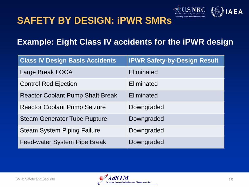
SAFETY BY DESIGN: iPWR SMRs
Example: Eight Class IV accidents for the iPWR design Class IV Design Basis Accidents iPWR Safety-by-Design Result
Large Break LOCA Eliminated
Control Rod Ejection Eliminated
Reactor Coolant Pump Shaft Break Eliminated
Reactor Coolant Pump Seizure Downgraded
Steam Generator Tube Rupture Downgraded
Steam System Piping Failure Downgraded
Feed-water System Pipe Break Downgraded

20 SMR: Safety and Security
ACTIVE VS PASSIVE SAFETY • Active safety systems require external power, force,
action or signal • Decay heat removal may require:
• Electric actuation signal • Motor-driven (or manually operated) valve to open • Pump to operate to establish coolant flow
• Need for external power creates accident vulnerabilities (Fukushima) but can be mitigated by multiple redundant and diverse external power sources

21 SMR: Safety and Security
ACTIVE VS PASSIVE SAFETY (cont’d) • Passive safety systems operate on laws and forces
of nature • SMR decay heat removal may require:
• Natural convection of coolant water (heated water rises, cooled water sinks)
• Natural circulation of water by forces of convection and gravity
• No coolant pumps needed • Passive systems still have vulnerabilities (forces of
nature are weak) but are more reliable and robust

ACTIVE PWR vs PASSIVE iPWR SMR
Passive iPWR SMR
Active LWR

23 SMR: Safety and Security
NRC AND IAEA TREATMENT OF ACTIVE vs PASSIVE • NRC classifies structures and components in 10
CFR 54.21(a)(1)(i), • “Structures and Components Subject to Aging
Management Review” • Passive: Reactor Vessel, Reactor pressure boundary,
Steam generators, Pressurizer, Piping, Pump casings, Valve bodies, Core shroud, Component supports, etc.
• Active: Pumps, Valves, Motors, Diesel generators, Air compressors, Snubbers, Control rod drive, Ventilation dampers, Pressure transmitters, Water level indicators, etc.
•

24 SMR: Safety and Security
NRC AND IAEA TREATMENT OF ACTIVE vs PASSIVE (Continued)
• IAEA (1991) specifies level of passivity ranging from Category A (most passive with no signals, external forces, power sources, moving parts or fluids) to Category D the least passive and requires: • Energy from stored sources or elevated fluids (no
power from normal AC) • Active components are limited to controls,
instrumentation and valves • Manual initiation is excluded
• Gen III+ LWRs use many passive safety components and systems

25 SMR: Safety and Security
DESIGNING BEYOND DESIGN BASIS EVENTS (DBE) - FUKUSHIMA
• Fukushima is a classic beyond DBE
• Safety systems at the plants were not designed to withstand the event
• Fukushima led to “stress tests” for existing plants and “FLEX” to mitigate the consequences of extreme events

26 SMR: Safety and Security
DESIGNING BEYOND DESIGN BASIS EVENTS (DBE) – FUKUSHIMA (Continued)
• Fukushima lessons learned resulted in 4 considerations that provided an opportunity for SMRs to design for beyond DBEs: • Low probability events still happen • Reliance on electrical power to prevent core damage is
a substantial vulnerability • Designing for a grace period of 24 or even 72 hours to
prevent core damage may not be sufficient • Multiple reactor units must plan for events in one unit
to impact other units

27 SMR: Safety and Security
SMR DESIGN LESSONS LEARNED ON BEYOND DBEs
• Not all conceivable low probability events should be designed for – apply a rational cost vs. benefit analysis
• Design and implement multiple and redundant safety systems – “defense in depth” – when it makes sense to do so
• SMRs will develop PRAs to statistically assess whether an accident sequence will result in significant core damage, or core damage frequency (CDF)

28 SMR: Safety and Security
SMR DESIGN LESSONS LEARNED ON BEYOND DBEs (cont’d)
• CDFs for SMRs - one probable core damage event in nearly a billion years
• SMR designs have unlimited cooling grace period
• SMR multi-module designs will ensure that an event at one module will not initiate or exacerbate an event at another unit

29 SMR: Safety and Security
LWR SMR DESIGN SAFETY FEATURES Safety aspects of iPWR with integrated pressure vessel include: • Eliminates large coolant pipes • Heat exchangers above core facilitates natural circulation • Larger water volume per unit power for decay heat removal • Steam generators in primary vessel provides heat sink and facilitates
passive cooling of secondary systems • Internal control rod drive mechanisms eliminate rod ejection
accidents and reduce penetrations • Large water volume between core and primary vessel provides
additional shielding and reduces pressurized thermal shock
30 SMR: Safety and Security
iPWR SMR Safety Features (cont’d) • Pipe penetrations that are small and generally positioned high
on the RPV (increased amount of water in core after a hypothetical pipe break)
• Depressurization of RPV by safety-grade system to allow gravity feed of secure water
• Decay heat removal from reactor core by passive safety systems
• Natural circulation normal core cooling or use of many low head reactor coolant pumps to greatly reduce or eliminate traditional loss-of-flow accidents

31 SMR: Safety and Security
iPWR SMR Safety and Security Features (cont’d) • Smaller radioactive source term
• iPWR features establishes technical justification for
siting SMRs near electricity load centers, with the smaller EPZ.
• Safety system can be powered purely by gravity and does not rely on pumps or motors.

32 SMR: Safety and Security
SMR ENHANCED SAFETY BY PRA PRAs assess the probabilities and consequences of multiple failures of systems and components which lead to beyond DBEs and result in core damage or releases of radionuclides to the public. Important characteristics of SMR designs critical to PRA-informed and safety outcomes include: • Defense-in-depth design features provide additional safety
barriers • PRA-guided design enhances safety • PRA application to reduce emergency planning zone (EPZ) • Smaller plant permits underground siting and seismic
isolation • Better security, not subject to external natural hazards,
reduces aircraft impact

33 SMR: Safety and Security
Example: NuScale iPWR SMR (50 Mwe) • Relies on natural forces (convection, conduction, and gravity) for
its normal ops and safety features
• Uses a factory-manufactured containment vessel to house the reactor vessel, steam generator, heat exchangers, and other components. The completed module is shipped to the site
• A NuScale power plant can include as many as 12 modules (600 MWe gross)
• It does not require backup sources of electricity to enter a safe cooldown condition after a total loss offsite power

34 SMR: Safety and Security
Example: NuScale iPWR SMR (Cont’d)
• Minimal safety-related valves (failed-safe position for actuation of the emergency core cooling system
• Passive cooling capacity is designed for unlimited period of core cooling with no need for pumps or additional water
• It would be placed in a below-grade, stainless steel–lined concrete pool, containing 8 million gallons of water
• Normal operations - heat is removed from the pool through a closed loop cooling system and ultimately rejected to the atmosphere
• On loss of AC power decay heat is transferred to the reactor pool by passive safety systems.

35 SMR: Safety and Security
Example: NuScale iPWR SMR (Cont’d) • After an extended period, the pool inventory will be
reduced and there is a transition to air-cooling by natural circulation
• In the course of a design-basis accident scenario, there is never a time when the reactor core is not covered with water.
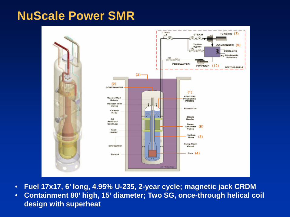
NuScale Power SMR
• Fuel 17x17, 6’ long, 4.95% U-235, 2-year cycle; magnetic jack CRDM • Containment 80’ high, 15’ diameter; Two SG, once-through helical coil
design with superheat
37 SMR: Safety and Security
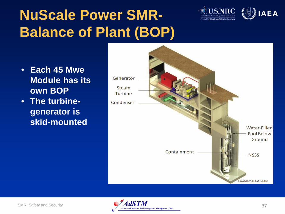
NuScale Power SMR- Balance of Plant (BOP)
• Each 45 Mwe Module has its own BOP
• The turbine-generator is skid-mounted
38 SMR: Safety and Security
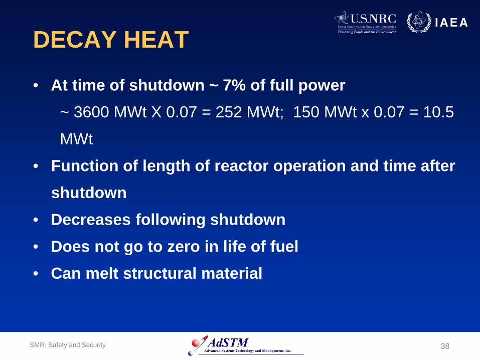
DECAY HEAT
• At time of shutdown ~ 7% of full power ~ 3600 MWt X 0.07 = 252 MWt; 150 MWt x 0.07 = 10.5
MWt
• Function of length of reactor operation and time after shutdown
• Decreases following shutdown • Does not go to zero in life of fuel • Can melt structural material
39 SMR: Safety and Security
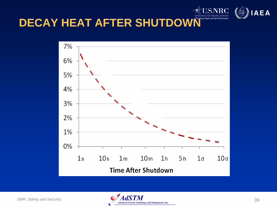
DECAY HEAT AFTER SHUTDOWN

40 SMR: Safety and Security
DECAY HEAT (cont’d) • Reactor heat up phenomena
• rapid oxidation of the zircaloy cladding • melting of the cladding • melting of the fuel
• Radioactive material released when fuel overheated or
melted
• Decay heat must be removed at all times
• Traditional reactors must have emergency core cooling systems (ECCS) to remove decay heat

NuScale Long-term Containment Cooling
At 1 second: 150 MWth x 0.067 = 10 MWth