smoke and heat exhaust control unit mcr 9705smoke and heat exhaust control unit mcr 9705 – user...
TRANSCRIPT
Nr dok: HO.18.00313 EN.doc rew.: B z dn.: 09.10.2018
Gdańsk, 09.10.2018 r.
Technical and Operating Documentation
User Instruction Manual
Smoke and Heat Exhaust Control Unit mcr 9705

Smoke and Heat Exhaust Control Unit mcr 9705 – User Instruction Manual
Strona 2 z 24
Table of Contents 1. Introduction .......................................................................................................... 3 2. About the mcr 9705 control unit ........................................................................... 4
3. Exploitation ........................................................................................................... 8 4. Assembly and start up ........................................................................................ 12 5. Instruction manual for checking connection and performance of the mcr 9705
control unit .......................................................................................................... 14 6. Typical connection diagrams .............................................................................. 16
7. Service and maintenance ................................................................................... 20 8. Warranty terms and conditions ........................................................................... 20 9. Technical specifications ..................................................................................... 22 10. The Declaration of Performance ........................................................................ 23 11. European Certificate of Constancy of Performance ........................................... 23
We recommend keeping this Instruction Manual inside the control unit, so that the information is always available when required!
The mcr 9705 control unit meets the requirements of the National Technical Assessment CNBOP-PIB-KOT-2018/0051-1009 issue 2 and the essential requirements of EU directives: 2014/35/EU (LVD) regarding electrical equipment provided for use within
certain voltage limits;
2014/30/EU (EMC) regarding electromagnetic compatibility.
Related documents: - European certification of constancy of performance of construction
products CNBOP-PIB No.1438-CPR-0607 and The Declaration of Performance No. 092/HO/2018 of 12/09/2018 confirming the compliance of the power supply with the requirements of EN 12101-10: 2007.
- EU Declaration of Conformity No. 091/HO/2018 dated 09/12/2018.
The above documents can be downloaded from the "MERCOR” S.A. company website - www.mercor.com.pl
Thank you for selecting the mcr 9705 control unit. Please, read these instructions carefully and follow the guidelines. This will ensure smooth and reliable operation of the device.
“MERCOR” S.A. reserves the right to modify the product or the documentation without notice.
We wish to ensure your full satisfaction with our products and we will be glad to provide You with professional service and assistance if necessary.
„MERCOR” S.A.
Electrical and electronic equipment should be disposed of and collected separately.
18
1438
Smoke and Heat Exhaust Control Unit mcr 9705 – User Instruction Manual
Strona 3 z 24
1. Introduction
The mcr 9705 control unit is used in smoke exhaust systems to control the operation of:
- electrical actuators and in particular vent actuators in mcr PROLIGHT, mcr THERMOLIGHT, mcr ULTRA THERM, mcr LAM, mcr LAM-N,
- valves of alarm boxes with CO2 cartridges, - drive of automatic rolled curtains PROSMOKE CE/CE1, mcr
PROSMOKE FSv2 CE, - electromagnetic door locks and in other mcr series products used for fire
protection purposes, which require 24 V= power supply.
The electrical mcr 9705 unit should be installed near the smoke exhaust window or in the building supervision room. The unit is powered with 230 V AC voltage. The working DC voltage is 24 V on output terminals to which the devices of the electrical smoke exhaust control system are connected. The unit is equipped with batteries which ensure system operation for 72 hours after a power outage. After that time a single emergency opening of smoke vents is possible. If the mcr 9705 control panel is used to control the PROSMOKE FSv2 CE mcr curtains, the standby time depends on the number of connected curtains (for details refer to the mcr PROSMOKE FSv2 CE curtains).
The unit has the following features: • automatic alarm release by a signal from a fire alarm control unit
• manual alarm release by alarm pushbuttons,
• automatic alarm release by smoke sensors,
• transmitting information about alarm (NO/NC signal),
• transmitting information about the defect of the system (NO/NC signal),
• transmitting information about vent opening (NO/NC signal),
• manual opening of a smoke vents for ventilation of the building during normal operation without activating the alarm status,
• automatic closing of smoke vents opened for ventilation, in case of rain or strong wind (when a weather monitoring unit with a wind-rain sensor is installed).
The mcr 9705 unit is equipped with audio and visual alarm indicators of its operating status, which allows easy identification of the alarm’s source or a system defect.
Smoke exhaust vents which were opened in emergency mode can be closed (cancellation of the alarm state) providing that the cause of the alarm has been removed. If mcr 9705 is equipped with manual pushbutton mcr RPO-1, remote operation and display of the unit’s status is possible (defect and alarm signals, remote alarm reset and closing vents after the alarm). mcr 9705 is performed in two series of type, which are based on modules: - 5 A, 2 x 5 A, 3 x 5 A, 4 x 5 A, 5 x 5 A, 6 x 5 A, 7 x 5 A, 8 x 5 A; or - 8 A, 2 x 8 A, 3 x 8 A, 4 x 8 A, 5 x 8 A, 6 x 8 A, 7 x 8 A, 8 x 8 A. Series of type [8A] shall be used only for natural smoke and heat exhaust systems.

Smoke and Heat Exhaust Control Unit mcr 9705 – User Instruction Manual
Strona 4 z 24
Closing of the vent after its emergency opening (deleting the alarm state) takes place after the cause of the alarm has been removed. Connecting of the mcr RPO-1 manual smoke exhaust pushbutton enables remote control panel operation (alarm enabling, alarm deleting and closing the vent after the alarm) and remote signalling of the system status (READY, FAULT, ALARM).
2. About the mcr 9705 control unit
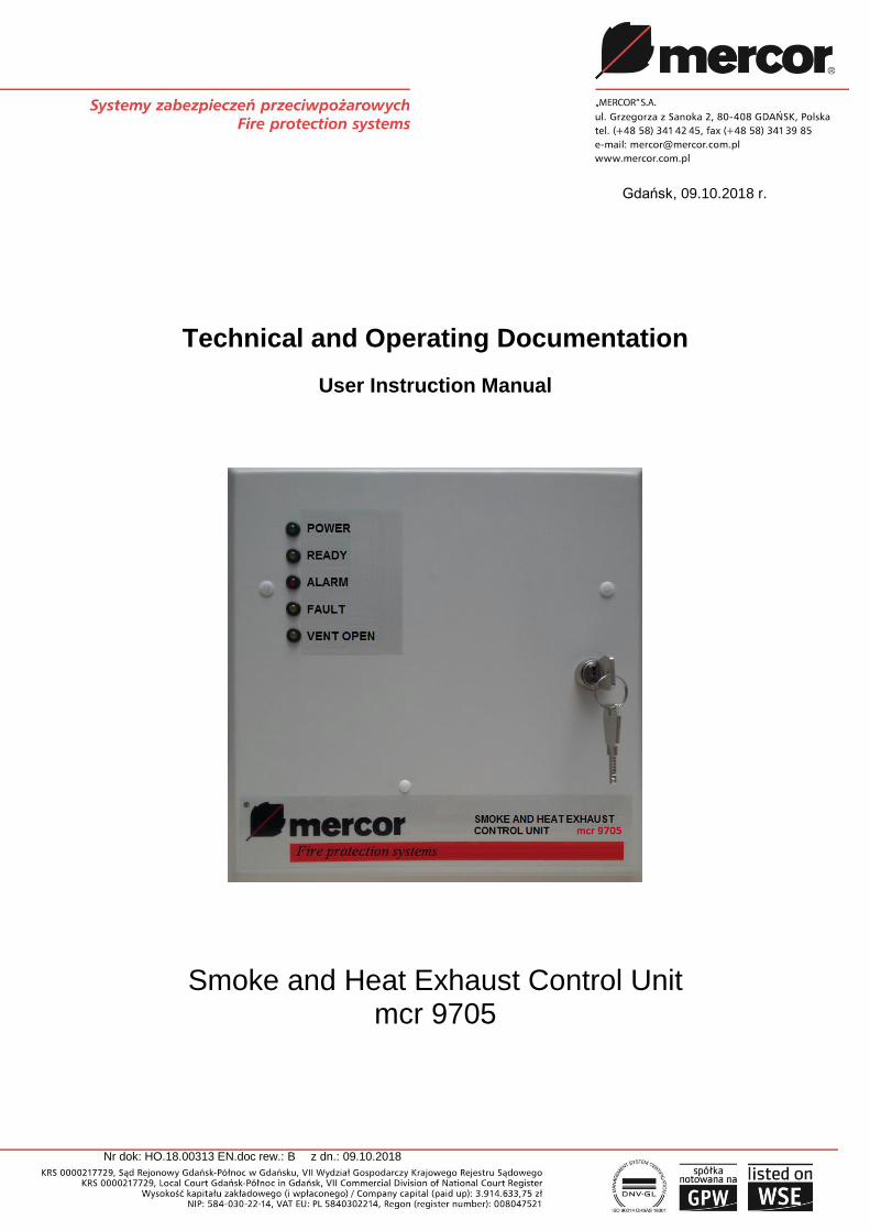
Pic. 1 Front panel of a control unit.
On the front panel, there are diodes which indicate the status of the control center:
No. Description Color Function
1 POWER SUPPLY green indicates that both power supplies are present
2 READY yellow indicates no alarm, system ready for operation
3 ALARM red optical alarm indicator
4 FAULT yellow general system failure signal
5 VENT OPEN or: CURTAIN (DOOR CLOSED)*
red indicates that smoke vents are open or door closed*
* doors closed (in remote door control systems).
As a standard, the control unit is equipped with a lock (6).

Smoke and Heat Exhaust Control Unit mcr 9705 – User Instruction Manual
Strona 5 z 24
Pic. 2 Inside view of the control unit’s door.
On the inside of the control unit’s door there’s an audio alarm device (22) and the optical indicator board (23). Optical indicators are used for the system diagnostics:
Item Color Information
7 red alarm; source: sensor line
8 red alarm; source: pushbutton line
9 red alarm; source: external input terminal
10 yellow defect to the actuator line (line gap)
11 yellow defect to the sensor line (line gap)
12 yellow defect to the pushbutton line (line gap or short-circuit)
13 not installed
14 yellow not used
15 yellow disconnection of the sensor line (SW1-2)
16 yellow disconnection of the pushbutton line (SW1-3)
17 yellow disconnection of the in/out connectors providing information about alarm and defect (SW1-4)
18 green power supply (same as on the front panel)
19 yellow ready (same as on the front panel)
20 yellow check – testing the correct operation of signals
21 red indication of open vent or dropped curtain (same as on the front panel)
22
23
7 8 9
10 11 12 13
14 15 16 17
18
19
20
21

Smoke and Heat Exhaust Control Unit mcr 9705 – User Instruction Manual
Strona 6 z 24
Pic. 3 Interior view of the control unit.
At the bottom of the control unit module there is a multi-function button:
No. Description Function
24
RESET
in the alarm state - deleting the alarm and closing the vent
in the state of supervision - closing the vent
Press the button for at least 1 second!
To the left of the RESET button there is an eight-position switch SW1 (27), designed to set the functions of the control unit:
Switch position Function
SW1-1 Disconnection of the actuator line
SW1-2 Disconnection of the sensor line
SW1-3 Disconnection of the ROP pushbutton line
SW1-4 Disconnection of the in/out relay contacts
SW1-5 Full opening of the vents during non-emergency ventilation in in "ventilation" and "hatch" mode
SW1-6 Activation of the mode – “door’s control”
SW1-5 + SW1-6
Enabling the electric locking drive/ activating alarm boxes ------------------------------------------------------------------------ Activation of automation mode in mcr PROSMOKE CE/CE1 curtain (for control panels with the "curtain" option)
SW1-7 -
SW1-8 Disabling the autoreset function
Note: the default setting for SW1-1 to SW1-7 – is OFF position, SW1-8 – is ON position.
Smoke and Heat Exhaust Control Unit mcr 9705 – User Instruction Manual
Strona 7 z 24
Above the RESET pushbutton there are jumpers regulating the vent’s opening time in ventilation and entrance mode (combinations of settings can be found in Chap. 3.2):
No. Description Function
46 H6 depending on the combination created with the H5 jumper
47 H5 depending on the combination created with the H6 jumper
Along the top edge of the module's PCB there are terminal strips which are used to connect the system’s elements:
No. Description Function
28 P6 Input for ventilation (U-up, D-down, ┴ - joint, closing contacts)
29 P7 input for wind/rain controls (closing contact)
30 P8 output for actuators (-,+)
31 P9 RPO(+,-) pushbutton line
32 P10 control input from ROP-1 (R,U)
33 P11 sensor’s line (+,-)
34 P12 power supply of the alarm signal loop (+, -)
35 P13 external alarm input, 24V= relay
36 P14 alarm indication output - relay contact
37 P15 defect indication output - relay contact
38 P16 programmable / service output (ex. opening the vent/ door closing) - relay contact
39 P17 RPO-1 indication output (1, 2, 3)
48 P19 power supply for alarm signaling loop (-, +) Note: For control units designed for the purpose of a smoke curtain, above the elements [30,44]
there is additional 4 poles terminal strip for mcr PROSMOKE CE/CE1 curtains’ actuators.
There are two additional entries in the upper right corner:
No. Description Function
25 P1 key switch input
26 P2 programmable / service input
Moreover, in the lower right corner there are:
No. Description Function
40 P4 positive pole of the battery
41 P5 negative pole of the battery
On-board fuses:
No. Description Function
43 FS1 batteries protection (6.3 A or 8 A* quick)
44 FS3 actuator’s line protection (6.3 A or 8 A* quick)
230 V 50 Hz power supply is connected to the terminal strip (42) in the top left
corner of the assembly board (inside the control unit).
Overload circuit breaker FS2 (45) – C 4 A or 6 A* on the assembly board provides protection for the 230 V mains circuit and the possibility for disconnecting power supply.
Smoke and Heat Exhaust Control Unit mcr 9705 – User Instruction Manual
Strona 8 z 24
There are following sizes of overload circuit breaker:
Central unit type: Circuit breaker type:
mcr 9705-5A C4A
mcr 9705-8A C6A
mcr 9705-10A, -15A, -16A C10A
mcr 9705-20A until -50A D10A
mcr 9705-55A and above D16A
3. Exploitation
3.1. Normal operation
On the front panel (Pic. 1) are placed following indicator lights:
yellow diode - READY
green diode - POWER SUPPLY Description of the optical indicators on the front panel:
PO
WE
R S
UP
PLY
`
RE
AD
Y
ALA
RM
FA
ULT
VE
NT
OP
EN
UNIT STATUS
+ VENT OPEN □ ANY STATUS
- VENT CLOSED
B ACTUATOR IN OPERATION + ON
- + ALARM
+ + - - NORMAL OPERATION - OFF
- - B MAINS FAILURE
+ - - + DEFECT B BLINKS
+ - - - DISCONNECTION
mcr 9705 is a maintenance-free device. It requires constant 230 V mains power supply. In case of power shortage caused by mains failure, the installed batteries will ensure 72-hour emergency power supply. Any power outage exceeding 72 hours can result in permanent damage of the batteries.
3.2. Non-emergency ventilation (daily ventilation) For smoke vents equipped with electrical smoke exhaust actuators and the
system with ventilation pushbuttons, it is possible to open smoke vents for non-emergency ventilation of the building in the normal usage conditions. When the
pushbuttons ( or ) are pressed and held down for at least 1 s, the vents are being open or close, respectively.
Pushing the button will always cause the smoke vent to be closed
completely. The function of the button depends on the position of the SW1-5 switch in the unit module (Pic. 3 item 27):
SW1-5 OFF - The vent opens only when the button is pressed (default setting), but no longer than for the time specified by the settings

Smoke and Heat Exhaust Control Unit mcr 9705 – User Instruction Manual
Strona 9 z 24
on the jumpers H6 and H5 (Pic. 3 item 46 and item 47 table of settings below),
SW1-5 ON - Pressing the button once causes the vent to open for the time specified by appropriate settings on the H6 and H5 jumpers (Pic. 3 item 46 and item 47).
Pic. 4 Sample ventilation button and a two-position key switch.
If the system is additionally equipped with a key switch (Pic. 4), setting the ignition switch in the "1" position activates the "hatch" mode in place of the "ventilation" mode. When "hatch" mode is active: - the weather station’s displays don’t cause vent’s closing,
- it is not possible to close the vent with the ventilation button , - the vent opens, just like in "ventilation" mode, by pressing the ventilation button,, - the time of opening the damper depends on the settings on the H6 and H5 jumpers, the vents:
Jumper: Condition: Opening time in:
„ventilation mode” „ventilation mode”
H6 - depending on how long ventilating button is pressed down (maximum 140 seconds) H5 -
H6 present* 20 s 45 s
H5 present*
H6 - 15 s 40 s
H5 present
H6 present 10 s 35 s H5 -
*default settings
NOTE!!
The ventilation function is inactive when an emergency alarm is active or if there’s mains power outage!

Smoke and Heat Exhaust Control Unit mcr 9705 – User Instruction Manual
Strona 10 z 24
3.3. Automatic weather monitoring unit
If the system is equipped with wind and/or rain sensor, the sensor will prevent from opening of the smoke vents for non-emergency, daily ventilation in adverse weather conditions. The wind/rain sensor will automatically close smoke vents (or prevent the vents from being opened by using the ventilation pushbutton) if the wind or atmospheric precipitation is too strong.
Note!
1. In case of the ALARM signal, smoke exhaust vents will be opened regardless of weather conditions!
2. Do not use alarm buttons for non-emergency ventilation!
3.4. Emergency alarm
If the status of the unit is in the ‘alarm’ state, the red ALARM diode on the front panel will light up, the audio alarm indicator will go off and the yellow “VENT OPEN” diode will blink to indicate operation of actuators. Once the smoke vents are open, the VENT OPEN diode will stay on.
In automatic door mode, in the ALARM state, the control panel cuts off the power from the actuators, which releases the door holders.
The door automation mode is also used to control the operation of mcr PROSMOKE FSv2 CE smoke curtains. In this case, after cutting off the power from the actuators, the curtains automatically fall into the working position.
NOTE: the door automation mode is not intended for the controlling the mcr PROSMOKE CE/CE1 curtains.
In the electric locking drive/activating alarm boxes, in the ALARM state, the control panel gives a fixed 24 V signal, but does not give a signal with reversed polarity in the alarm reset state.
Alarm release methods: Manual - break the glass of the smoke release pushbutton and push the button.
Automatic – depending on the type of sensors used, they will be automatically activated when the temperature rises or the smoke conditions will appear.
Automatic release from an external source – a signal from an external device (e.g. Fire Alarm Unit) is supplied to the alarm signal-in terminals of the control unit (Pic. 3 item 35). The alarm will cause 24 V power outage on P13 terminals.
3.5. Deleting an emergency alarm To delete the alarm status, one first needs to open the unit with the correct key
and determine the source of alarm, using the optical indicators inside the unit (Pic. 2). Depending on the source of the alarm, remove its cause and reset the alarm:
After manual alarm release (the RPO line), replace the glass in the alarm
Smoke and Heat Exhaust Control Unit mcr 9705 – User Instruction Manual
Strona 11 z 24
pushbutton, delete the alarm either using the RESET button on the casing of the control unit or by using the ALARM RESET button in the RPO-1 unit (hold the button down for at least 1 s). The red ALARM diode will be turned off, and the yellow READY diode will light up.
After alarm release from a smoke sensor (the sensor line), delete the alarm using the RESET button. The sensor will not activate the alarm again if there’s no longer excessive smoke/high temperature. The red ALARM diode will be turned off, and the yellow READY diode will light up.
After alarm release from an external source (in/out) one first needs to delete the alarm in the device which initiated the response of the mcr 9705 control unit. Depending on the SW1-1 setting, there are 2 possible ways to delete the alarm: SW1-8 in ON position - After deleting the alarm in the device which initiated the response of control unit, delete the alarm with the RESET key. The ALARM diode goes out, the READY diode lights up. SW1-8 in the OFF position - After deleting the alarm in the device which initiated the response of the control unit it will be cleared automatically (in door automation mode with a delay of 75 s). The ALARM diode goes out, the READY diode lights up. The actuators of the devices will be actuated by the control unit in the closing direction. Then delete the alarm using the RESET button. The red ALARM diode will be turned off, and the yellow READY diode will light up. If the cause of the alarm can’t be removed (for example, when there’s an alarm source failure), one needs to access the segment representing the relevant alarm source in the SW1 switch in the control centre module (Pic. 3 item 27) and adjust it from the “OFF” to the “ON” position (in accordance to the description on the optical signal board – disconnection of the RPO/sensor/in-out line). In next step delete the alarm using the RESET button. The red ALARM diode will be turned off. The yellow READY diode will not light up.
In this case CALL THE SERVICE
3.6. Closing the vents after alarm release To close the vent, the alarm must first be deleted. After the alarm has been
deleted, the vent will close automatically. The red “VENT OPEN” diode will begin to blink, indicating the operation of actuators. Once the smoke exhaust vents are closed, the “VENT OPEN” indicator will be turned off (after approx. 140s.)
3.7. Diagnosis of the faults Optical indicators (Pic. 2) placed on the inside part of the central unit’s door
enable identification of the system’s defects.
A blinking “FAULT” diode provides information about the mains failure or batteries failure. In this case, one has to check whether there’s voltage (230 V) on the control unit’s terminals and the status of FS1 and FS2 cut-out fuses (see page 7).
If there is a signal indicating a fault in the actuator line, check the on board fuse FS3.
Smoke and Heat Exhaust Control Unit mcr 9705 – User Instruction Manual
Strona 12 z 24
Never change the default settings of the voltage potentiometer for the batteries.
In case of a system defect CALL THE SERVICE
3.8. Curtain control - Additional info For mcr PROSMOKE CE / CE1 curtains use the mcr 9705 control unit with the
"curtain" option. Set the control unit into the curtain control mode (SW1-5 and SW1-6 ON).
For mcr PROSMOKE FSv2 CE curtains, use the standard mcr 9705 control panel. The control panel should be set to door automation mode (SW1-6 ON).
The control unit’s standby time in cooperation with the curtains mcr PROSMOKE FSv2 CE depends on the number of connected smoke curtains - additional information in the DTR of mr PROSMOKE FSv2 CE smoke curtains.
4. Assembly and start up
1. Sensors line - 2 leads (e.g. YnTKSY) from P11 terminals. Terminal resistor 5,1 kΩ in the base of the last sensor. The maximum number of sensors is limited in accordance with the list of technical parameters (see chapter 9 Technical specifications).
2. Smoke exhaust pushbuttons line (RPO) - 7 leads from P9 (alarm closing contact), P10 (control inputs) and P17 terminals (indicator output). Terminal resistor 10 kΩ in the last pushbutton. The maximum number of pushbuttons in accordance with the technical parameters (see page 20).
3. Actuators line - 2 leads in silicone insulation (feature PH30, for example HLGs), from P8 terminals. Terminal resistor 10 kΩ in the last connection box. The line is protected by a 6,3 A or 8 A fuse (FS3). The maximum number of actuators in accordance with the technical parameters. Only specific leads shall be used, leads that are compatible with actual regulations.
Attention: In case of multi module centrals – do not connect galvanized outputs [to actuators] of different modules.
4. Ventilation - pushbuttons for ventilation (manual vent control- upwards, downwards) – 3 leads (e.g. YTKSY or YDY) from P6 terminals. It is possible to connect several pushbuttons in parallel.
5. Hatch function - switch with key (for switching between the functions "ventilation" - "hatch") - 2 wires (YTKSY or YDY) from terminals P1
6. Automatic weather monitoring unit for closing the vents in case of a strong wind/ heavy rain - 2 leads (e.g. YTKSY or YDY) from P7 terminals.
7. External alarm input to the 24 V relay coil – 2 leads (e.g. YnTKSY) from P13 terminals. If the device which activates the alarm (fire alarm control unit) has a 24 V output, it shall be connected directly to the P13 terminal. Loss of voltage at the P13 terminal will activate the alarm. If the device which activates the alarm is equipped with a voltage-free null contact (NC), we have to use the loop power supply available on the P12 terminal (see Diag. 1 or Pic. 3). The P12 terminal is short-circuit resistant and can carry a load of maximum two relays. Once the line is connected remove the H1 jumper which blocks the external alarm.

Smoke and Heat Exhaust Control Unit mcr 9705 – User Instruction Manual
Strona 13 z 24
8. Voltage-free output NC (or NO) for information about alarm – 2 leads (e.g. YnTKSY) from P14 terminals. The H2 jumper allows to select NC (default) or NO output.
9. Voltage-free output NC (or NO) for information about defect – 2 leads (e.g. YnTKSY) from P15 terminals. The H3 jumper allows to select NC (default) or NO output.
10. Voltage-free output NC (or NO) for information about vent opening – 2 leads (e.g. YnTKSY) from P16 terminals. The H4 jumper allows to select NC (default) or NO output.
11. Mains 230 V, 50 Hz should be connected to the terminal strip on the unit assembly board. The power supply for the unit should be separate (units only on the mains line), protected by means of a properly marked overload circuit breaker in the switching station. The recommended circuit breaker: I = number of control units * 4 A, or * 6A for series of type 8A. It is not recommended to connect more than eight units on a single line. Do not protect the line by means of a GFCI (RCCB) circuit breaker.
12. 24 V power supply from batteries (P4, P5). The batteries should be connected in series, taking polarity into account. Make the connection after the control unit has been launched by use of mains power supply.
13. Large systems – connecting multiple control units. In order to increase the number of sensors, ROP buttons or actuators connected to the system, one can connect multiple control units.
To relay an alarm from one control unit to another, use the P14 alarm output terminal and the P13 alarm input terminal with P12 power supply.
Do not connect output lines [to actuators] of different modules.
Control units can be connected together into ventilation sections. To do this, connect in parallel the P6 ventilation terminals of all control units in a section: U-up, D-down, ground-joint. Connect the weather monitoring unit only to one (any one) control unit in the section, to P7 terminals.
When connecting the weather monitoring unit to more than one ventilation section, connect individual units in parallel.
Important! - connect the P7 terminals on the left to one line, and the ones on the right to the other line - do not cross!
14. Remote door controls. The control unit is also adapted to operating in the remote door control mode. To switch on the door control mode, use the SW1-6 switch (set it to ON). Connect electromagnetic door locks to the P8 terminals.
15. Unlocking electric locking drive\ activation of alarm boxes. The control unit can work in the release mode of interphone installation and / or triggering alarm boxes. In order to activate the mode, the switches no. SW1-5 and SW1-6 should be set to the ON position.
16. Other devices activated only in the alarm state The mcr 9705 control unit has the option of connecting external devices supplied with 24 V = voltage, working in the alarm state, such as the SA-K7 optical-acoustic indicators. They can be connected in one of two options: - devices with their own power source should be connected with 2 wires (YnTKSY) via NC isolated (or NO) voltage output on terminal P16 (jumper H4 is used to select NC output - factory or NO),
Smoke and Heat Exhaust Control Unit mcr 9705 – User Instruction Manual
Strona 14 z 24
- in the case of a device without a separate power source, connect the 2 wires (YnTKSY) with the power supply from terminal P19. An example of both variants of connection is shown in Diag. 4. NOTE - the maximum load on the alarm loop terminals is 110 mA!
17. Start-up. Before switching on the power supply, check if the leads are connected properly. Note: the leads should be placed and connected in accordance with relevant standards and basic rules for wiring. First switch on the 230 V mains voltage, and only then connect the batteries. The reverse order is not recommended because of a large current surge that occurs during the charging of the condenser in the power supply adaptor.
18. In a correctly operating unit, the following LED indicator are on: READY, POWER SUPPLY, and VENT OPEN. When the CLOSE VENTS button is pressed, the VENT OPEN diode begins to blink and then switches off after about 5 minutes. When the actuator is in operation, the VENT OPEN diode keeps blinking.
19. In order to check the operation of ventilation, the weather monitoring unit should be disconnected. The weather monitoring unit blocks ventilation for several minutes after the wind has ceased, and in case of rain the sensor needs to get dry, which takes even more time.
20. The LEDs on the inside of the unit’s door make detailed defect identification possible. To test their operation, press the TEST button and hold it down for about 1 s. To test the operation of the audible alarm indicator, press simultaneously the TEST and RESET buttons.
Note: in order to connect the unit you should use leads which satisfy the requirements of current regulations.
5. Instruction manual for checking connection and performance of the mcr 9705 control unit
For reasons of operational safety and reliability of the fire protection system, after
installing the control panel, check the device by following instructions.
1. Check the correctness and reliability of connection of all cables (main power,
input and output lines, line continuity resistors) in accordance with with Operation
Manual and the installation design.
2. Check the value of the power supply voltage of the control unit - it should be
230 V %10
%15
, 50 Hz.
3. Perform the control panel start-up in accordance with the Operation Manual (Chapt. 4, par. 17, 18).
4. Check whether the control panel remains in the normal operating state (Chapt. 3.1).
5. After min. 12 hours of charging the batteries, check the voltage at the battery terminals. The measurement must be carried out in the normal operating state (Chapt. 3.1). The voltage at the battery terminals should be in the range of 26.5 ÷ 28 V =.
6. Perform auditing of optical and acoustic signalling (Chapt. 4, Par. 18, 20). 7. Check the correctness of fault detection by the control unit: damage to the sensor
line (e.g. take out the last sensor from the socket), damage to the RPO button
line (e.g. to open the RPO line, P9 terminal), damage to the actuator lines (e.g.
Smoke and Heat Exhaust Control Unit mcr 9705 – User Instruction Manual
Strona 15 z 24
open the actuators line, the control panel in mode smoke exhaust), power supply
damage (e.g. 230 V disconnect), battery detection (e.g. disconnect the batteries).
Tests should be performed in a normal operating state for any potential damage.
In each test case, the fault condition should be detected and signalled on the
front panel of the control unit, on the service panel for selected faults, by means
of the mcr RPO-1 button (if connected) and on the fault indication output (by
ohmmeter control).
8. Check whether the control panel is correctly detecting alarms. Check all
connected alarm sources:
a. alarm from the RPO line (press the mcr RPO-1 button),
b. alarm from the sensor line (activate the sensor),
c. alarm from the external alarm line (activate external device or open the line).
Tests should be performed in the normal operating state independently for each
connected alarm source. In any case, the alarm condition should be detected
and signaled by the control unit (Chapt. 3.4) on the front panel, on the service
panel with the diode of the proper alarm source, with the diode of the button mcr
RPO-1 (if connected) and on the alarm signal output (ohmmeter control), and all
connected fire devices controlled by the control panel should be controlled.
9. Check the correctness of the line disconnection signaling on the service panel: after switching the segments (1 ÷ 4) of switch SW1 (page 6) the appropriate LEDs should light up on the service panel, and the READY diode on the front panel should go out. After the test, restore the lines to the connection status.
10. If applicable, check that the daily ventilating function (Chapt. 3.2) and the programmable \ service output (page 7) are connected.
11. Check whether the control unit remains in the normal operating state after all tests have been performed (Chapt. 3.1).
12. The control panel can be put into operation if all tests have been completed
correctly. Only an efficient and properly connected control unit can work in fire
protection systems. In the event that at least one result of the above tests is not
correct, the control panel cannot be used in security systems and should be
restored for proper operation.
After checking the above points, make a record in all fields of the table below.
Date of control
Result: Working/not working
Name and surname
Name of enterprise:
“MERCOR” S.A.’s authorization no:

Smoke and Heat Exhaust Control Unit mcr 9705 – User Instruction Manual
Strona 16 z 24
6. Typical connection diagrams
Diag. 1 Typical configuration of a smoke exhaust system equipped with the mcr 9705-5A
control unit.
Elements:
CP - weather monitoring unit mcr P054 LT - ventilation pushbutton ŁNK - key switch for activating the "hatch" mode ME - electromechanical actuator OCD – optical smoke sensor (e.g. KL731) PM - connection box RPO – manual smoke exhaust pushbutton mcr RPO-1
Attention! Not all the elements of the system (in particular the fire protection control unit and the weather monitoring unit) must be present in the smoke exhaust system.

Smoke and Heat Exhaust Control Unit mcr 9705 – User Instruction Manual
Strona 17 z 24
Diag. 2 Typical connection of smoke curtain to control unit mcr 9705 (Execution for curtains
mcr PROSMOKE CE/CE1).
Elements: OCD – optical smoke sensor (sensors should be connected according to advice of
a manufacturer) RPO – manual smoke exhaust pushbutton mcr RPO-1 PM – connection box ME – electromechanical actuator 24 V = curtain mcr PROSMOKE CE/CE1 Attention! 1. Not all the elements of the system (in particular the connection with fire protection control unit) must be present in the smoke exhaust system. 2. Central unit or module operating with smoke curtain cannot be connected simultaneously to smoke vent’s actuators, weather central unit or ventilation push buttons.
Smoke and Heat Exhaust Control Unit mcr 9705 – User Instruction Manual
Strona 18 z 24
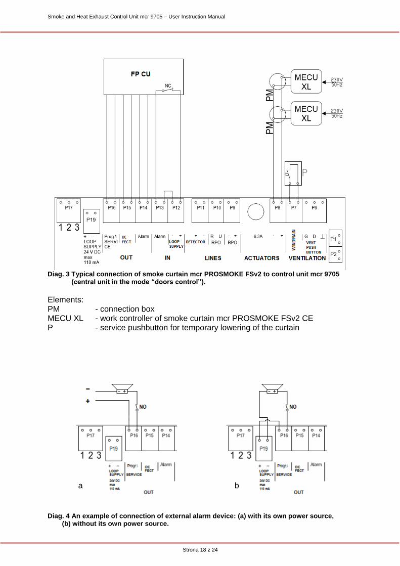
Diag. 3 Typical connection of smoke curtain mcr PROSMOKE FSv2 to control unit mcr 9705
(central unit in the mode “doors control”).
Elements: PM - connection box MECU XL - work controller of smoke curtain mcr PROSMOKE FSv2 CE P - service pushbutton for temporary lowering of the curtain
Diag. 4 An example of connection of external alarm device: (a) with its own power source,
(b) without its own power source.
b a
Smoke and Heat Exhaust Control Unit mcr 9705 – User Instruction Manual
Strona 19 z 24
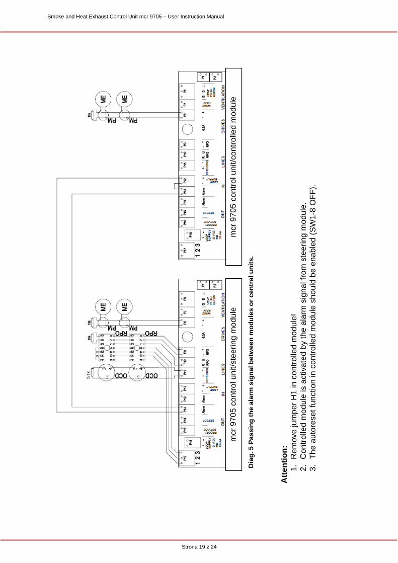
Dia
g. 5 P
assin
g t
he a
larm
sig
nal b
etw
een
mo
du
les
or
cen
tral u
nit
s.
Att
en
tio
n:
1.
Rem
ove
ju
mp
er
H1
in
co
ntr
olle
d m
od
ule
!
2.
Con
tro
lled
mod
ule
is a
ctiva
ted b
y th
e a
larm
sig
na
l fr
om
ste
ering
mo
du
le.
3.
Th
e a
uto
rese
t fu
nction
in c
on
tro
lled
mo
du
le s
ho
uld
be
ena
ble
d (
SW
1-8
OF
F).
mcr
97
05
co
ntr
ol u
nit/s
tee
rin
g m
od
ule
m
cr
97
05
co
ntr
ol u
nit/c
on
tro
lled m
od
ule

Smoke and Heat Exhaust Control Unit mcr 9705 – User Instruction Manual
Strona 20 z 24
7. Service and maintenance The technical condition of fire protection devices installed in the facility is of key importance to ensure the safety of users of this facility. The guarantee of reliable operation of the devices can only be obtained by providing regular and professional service care. “MERCOR” S.A. they should be subjected to periodical technical inspections and maintenance operations every six months during the entire period of operation, i.e. during the warranty period, as well as after the warranty period. Inspections and maintenance should be carried out by the manufacturer or by companies having valid authorization for the service of devices “MERCOR” S.A. The service carried out in accordance with the above recommendations is one of the basic conditions of preservation of rights arising from the guarantee and the obligation of the users / owners or managers of the resulting facilities from the law. The obligation to carry out service inspections of fire-fighting equipment results from the provisions of the Ordinance of the Minister of Interior and Administration of June 7, 2010 on fire protection of buildings, other construction objects and areas (Journal of Laws of 2010 No. 109, item 719). In order to be able to perform activities included in the scope of service inspections, as well as service and warranty activities such as visual inspection or repair, it is necessary to provide physical access to the devices. It is recommended to perform those check-ups in between of inspections: 1. Checking the status of signaling of control LEDs. 2. Checking the condition of electrical connections paying special attention to
looseness and mechanical damage. In matters related to technical inspections, maintenance and repairs of devices, you can contact representatives of “MERCOR” S.A., tel. +48/ 58 341 42 45 during operating hours 8 - 16 (Mon-Fri), e-mail: [email protected].
8. Warranty terms and conditions
1. “MERCOR” S.A. grants a 12-month quality guarantee for equipment, starting from the date of purchase, unless the agreement provides otherwise.
2. If during the term of guarantee any physical defects of the equipment become evident, “MERCOR” S.A. shall remove them within 21 days of the written notification, subject to paragraph 6.
3. “MERCOR” S.A. reserves the right to lengthen the repair time in the event of complicated repairs or those that require non-standard sub-assemblies [elements] or spare parts to be purchased.
4. Liability under the Guarantee covers only defects resulting from causes inherent in the equipment sold.
5. In the event of defects resulting from inappropriate operation of the equipment or due to other reasons stated in par. 6, the Buyer/Guarantee Holder shall bear the costs of their removal.
6. The guarantee does not cover:
damages and breakdowns of the equipment due to inappropriate operation, user’s interference, lack of maintenance or periodic servicing;

Smoke and Heat Exhaust Control Unit mcr 9705 – User Instruction Manual
Strona 21 z 24
equipment damages resulting from causes other than those that “MERCOR” S.A. is responsible for, in particular: acts of God such as torrential rainfall, flood, hurricane, flooding, stroke of thunder, overvoltage in the mains, explosion, hail, fall of aircraft, fire, avalanche, landslide and secondary damages due to the above-listed causes. Torrential rain is defined as rain with an efficiency index of at least 4 (or 5 in Chomicz scale or torrential rain grade IV (A4)). Should it be impossible to determine the index mentioned in the previous sentence, the actual condition and the degree of damage at the place of its origin proving that it is the consequence of torrential rain will be considered. Hurricane is defined as wind blowing at the speed of at least 17.5 m/s (damages are deemed to have been caused by hurricane if the effects of hurricane have been found in the immediate neighborhood);
damages due to failure to immediately report the defect discovered;
worsened quality of coating due to the natural ageing process (fading, oxidation);
defects due to using abrasive or aggressive cleaning products;
parts liable to natural wear and tear during operation (e.g. seals) unless a manufacturing fault has occurred;
damages due to aggressive external factors, especially chemical and biological ones.
7. Each defect under guarantee should be reported to a local representative of “MERCOR” S.A. immediately, i.e. within 7 days of its discovery.
8. Applications can be made by phone at +48/ 58 341 42 45, by email to [email protected] or by sending a letter to: “MERCOR” S.A. 80-408 Gdańsk, Grzegorza z Sanoka 2.
9. The Buyer/Guarantee Holder is responsible for proper operation and maintenance of the equipment and for regular (min. twice a year) servicing.
10. The Guarantee shall expire forthwith if:
The Buyer/Guarantee Holder makes design modifications on his own without consulting “MERCOR” S.A.,
Maintenance or periodic servicing are not done in due time or are performed by unauthorized persons or a service center not authorized by “MERCOR” S.A., or the equipment is operated in the wrong way,
Any interference of unauthorized persons – except activities connected with normal operation of the equipment.
11. Moreover, in the cases specified in par. 10, “MERCOR” S.A. has no warranty obligations.
As regards matters not regulated by these "Warranty terms and conditions", relevant regulations in the Civil Code, and in particular Art. 577-581 shall apply.

Smoke and Heat Exhaust Control Unit mcr 9705 – User Instruction Manual
Strona 22 z 24
9. Technical specifications The data in the table below applies to the control panel with a single module:
Item Value
Base type: 5 A 8 A
Control unit type conventional
Power supply voltage – basic power supply 230 V %10
%15
50 Hz
Rated power 150 VA 250 VA
Output voltage (power supply for actuators) 24 V DC, max. 5,2 A
24 V DC, max. 8 A
Stand-by power supply 2 pcs. of batteries (3,2 Ah, 12 V) connected in series
Charging voltage for set of batteries 27,5 V 0,2 V @20C
Working temperature range -5C ... +55C
Maximum number of sensors in line: 20 pcs.*
Maximum number of RPO-1 pushbuttons: 8 pcs.
Maximum number of actuators – by type: MCRL KT10x and MCRL KR10x or KT10x and KR10x
5 pcs. 8 pcs.
MCRW 08x or G08x or SG08x or S08x 6 pcs. 10 pcs. MCRW 10x or G10x or SG10x or S10x 5 pcs. 8 pcs. MCRW 16x or G16x or SG16x 3 pcs. 5 pcs. MCRW 20x or G20x or SG20x 2 pcs. 4 pcs. MCRW 26x or G26x or SG26x 2 pcs. 3 pcs. MCRW 40x or G40x or SG40x 1 pcs. 2 pcs. MCRW 60x or G60x or SG60x - 1 pcs. MCRW 80x or G80x or SG80x - 1 pcs. (other types of electric actuators depending upon consumed and maximum current.)
- -
Maximum number of electromagnetic door locks – by type:
mcr TE 50 40 pcs. 40 pcs. mcr TE 100 30 pcs. 30 pcs.
The maximum number of curtain modules CE/CE1
2 pcs. Width < 4 m
2 pcs. Width >= 4 m
The maximum number of curtain modules FSv2 CE
12 pcs.
Operation time without mains voltage, in READY mode
min. 72 h**
Load for relay outputs max 100 mA, 24 V
Environmental class according to KOT I
Environmental class of the power supply according to PN-EN 12101-10
I
Protection level for housing IP 54
Dimensions (H x W x D) 300 x 300 x 120 mm
* In standby mode, the current consumption of 1 sensor cannot exceed 60 μA! ** After this time, the control unit can open actuators once and alarm for 30 minutes. The backup time in the door automation mode depends on the number of connected devices.

Smoke and Heat Exhaust Control Unit mcr 9705 – User Instruction Manual
Strona 23 z 24
10. The Declaration of Performance
11. European Certificate of Constancy of Performance

Smoke and Heat Exhaust Control Unit mcr 9705 – User Instruction Manual
Strona 24 z 24