smog-hog model sh-pp - clarcor industrial air ... smog-hog ® units consist of ... penney-type...
TRANSCRIPT
SMOG-HOGMODEL SH-PP
Owner’sManual

KNOW YOUR EQUIPMENT
READ THIS MANUAL FIRST.
IF YOU DO NOT FULLY UNDERSTAND THE INSTRUCTIONS, CONSULT YOUR LOCALREPRESENTATIVE BEFORE PROCEEDING WITH INSTALLATION OR OPERATION.
Your SMOG-HOG Air Cleaning System should provide many years of trouble-free service. Thismanual will help you understand the operation of your SMOG-HOG Air Cleaning System. It willalso help you understand how to maintain it in order to achieve top performance. For quick futurereference, fill in the system and filter information in the spaces below. To expedite your service,have the following information available when contacting UAS.
UAS ORDER REFERENCE: ______________________________________________________
UNIT MODEL: _________________________________________________________________
UNIT SERIAL NUMBER: ________________________________________________________
HIGH VOLTAGE POWER SUPPLY NUMBER: _______________________________________
SYSTEM ACCESSORIES:
______________________________________________________________________________
______________________________________________________________________________
______________________________________________________________________________
______________________________________________________________________________
INSTALLATION DATE: __________________________________________________________
SMOG-HOG CUSTOMER SERVICEUNITED AIR SPECIALISTS, INC.
4440 Creek RoadCincinnati, Ohio 45242
1-800-252-4647 FAX: 513-891-4882

TABLE OF CONTENTSPage
1. SAFETY PRECAUTIONS................................................................................. 1
2. UNIT NOMENCLATURES ................................................................................ 1
3. DESCRIPTION AND OPERATION................................................................... 13.1 Power Packs ............................................................................................... 23.2 Ionizers ....................................................................................................... 23.3 Collection Cells ........................................................................................... 23.4 Filters .......................................................................................................... 23.5 Junction Boxes ........................................................................................... 23.6 Other Equipment ........................................................................................ 2
4. INSTALLATION ................................................................................................. 24.1 Inspection of Equipment ............................................................................. 24.2 Storage ....................................................................................................... 24.3 Installation Planning ................................................................................... 34.4 Installation .................................................................................................. 3
5. OPERATION ..................................................................................................... 45.1 Pre-Start-up Checks ................................................................................... 45.2 Start-up....................................................................................................... 5
6. MAINTENANCE AND MANUAL CLEANING ................................................... 56.1 Routine Maintenance.................................................................................. 56.2 Manual Cleaning of SMOG-HOG Components .......................................... 56.3 Manual Cleaning Methods .......................................................................... 66.4 When Are Components Clean .................................................................... 7
7. TROUBLESHOOTING...................................................................................... 77.1 Tools Required ............................................................................................ 77.2 Checkout Before Testing ............................................................................. 87.3 Troubleshooting Procedures ....................................................................... 87.4 Power Pack/AC Voltage Checks ................................................................. 87.5 DC High Voltage Checks Without Utilizing A High Voltage Probe .............. 87.6 Measuring for High Voltage (DC Only) ....................................................... 97.7 Checking Ionizers ....................................................................................... 97.8 Checking Collection Cells ........................................................................... 97.9 Indicator Lamp ............................................................................................ 9
8. BENCH TEST PROCEDURE ......................................................................... 11
9. STANDARD PART REPLACEMENT PROCEDURES .................................... 129.1 Ionizer Wires ............................................................................................. 129.2 Door Feed-Through Insulator ................................................................... 129.3 Door Gasket ............................................................................................. 129.4 Replacement Parts List/Recommended Spare Parts ............................... 13
10. ORDERING PARTS........................................................................................ 1410.1 Replacement Parts ................................................................................. 1410.2 Returning Parts ...................................................................................... 1410.3 Freight Cost ............................................................................................ 14
11. FIGURES........................................................................................................ 15


Model SH-PP Owner’s Manual 1
1. SAFETY PRECAUTIONSThis manual contains important safety information andprecautionary measures. It is impossible to list allpotential hazards associated with the SMOG-HOG AirCleaning System in each application. Proper use of theequipment must be discussed with United AirSpecialists, Inc. (UAS) or your local SMOG-HOG®
representative. Operating personnel must be aware of,and adhere to, the most stringent safety procedures.
General
• The SMOG-HOG® must not be used in explosiveatmospheres.
• The SMOG-HOG® must not be used to collectemissions that are explosive.
• The SMOG-HOG® must not be used to collectemissions with a temperature higher than 120°Fwithout approval from UAS.
• The SMOG-HOG® must not be used to collectemissions with a water to oil ratio greater than 50:1without consulting with UAS.
Application
• The SMOG-HOG® is suitable exclusively forparticulate emission filtration only. Any other oradditional use is considered improper. Improper usemay cause damage to equipment or injury topersonnel.
• UAS will not accept liability for any damage resultingfrom such improper use. Risks are carried solely bythe user.
• The SMOG-HOG® is not suitable for filtration ofgasses.
Operation
• The SMOG-HOG® is only to be operated in a safeand serviceable condition.
• The SMOG-HOG® must be shut down immediatelyin the event of a defect. Faults must be rectified atonce.
• Do not operate the SMOG-HOG® with either the fanand motor compartment door or the collectioncomponent door open.
Maintenance
• The SMOG-HOG® must be switched off andisolated from the power source when carrying outmaintenance and repair work.
• Only suitable qualified personnel are to work on theelectrical systems.
• Exercise great care when handling the SMOG-HOG®
collection components, wear protective clothing andsafety glasses.
• Comply with local and national codes whendisposing of pollutants collected on the collectioncomponents.
2. UNIT NOMENCLATURESMOG-HOG® Air Cleaning Systems can include variouscombinations of plenums and conditioning devicesconnected in series in the direction of airflow. TheSMOG-HOG® unit configuration is clearly defined ondocuments and nameplates, refer to Figure 1.
SMOG-HOG® units consist of “modules,” each moduleacting as one electrical entity. Modular units designatedas “single-wide” (one module wide) have access doorsto collection components located such that, whenviewing the door, air passes from left to right. Oppositeside access is available, when viewing the door, airpasses from right to left specified, air passing from rightto left. “Double-wide” (two modules wide) units haveaccess doors on both sides. When an applicationdictates, multiple SMOG-HOG® units may be placed inseries in the direction of airflow, which could be a two-pass or three-pass SMOG-HOG® Air Cleaning System.
The nominal airflow rating of one ionizer and onecollector cell is 1,000 to 1,500 CFM.
3. DESCRIPTION AND OPERATIONThe SMOG-HOG® Air Cleaning System is a two-stage,Penney-type precipitator used for removal of submicronhydrocarbon emissions and other airborne contaminants.The two “stages” consist of an ionizer and a collector cell.
Each ionizer consists of a series of 15 mil tungsten steelwires, charged to a high DC voltage and centeredbetween a like series of grounded plates. Airborneparticles are charged positively through the ionizer’sintense electrostatic field.
Each collector cell consists of a large number of parallelplates, alternately charged with high DC voltage (thesame polarity as the ionizer but about half its voltage)forming a magnetic field. Charged particles aresimultaneously attracted to ground plates which arerepelled by charged plates, the result being a highlyefficient removal of charged particulate.
The ionizers and collector cells are preceded and/orfollowed by filter media to assure even distribution of air,at low velocity, through the collection components. Air
2 Model SH-PP Owner’s Manual
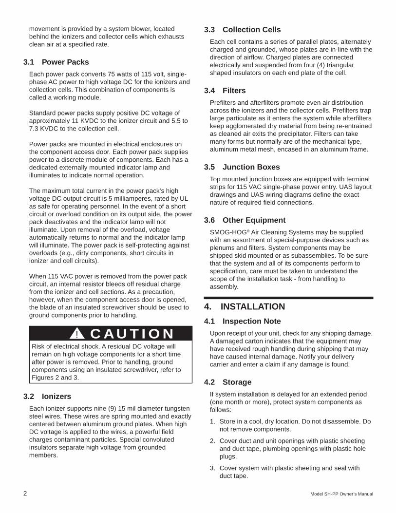
movement is provided by a system blower, locatedbehind the ionizers and collector cells which exhaustsclean air at a specified rate.
3.1 Power Packs
Each power pack converts 75 watts of 115 volt, single-phase AC power to high voltage DC for the ionizers andcollection cells. This combination of components iscalled a working module.
Standard power packs supply positive DC voltage ofapproximately 11 KVDC to the ionizer circuit and 5.5 to7.3 KVDC to the collection cell.
Power packs are mounted in electrical enclosures onthe component access door. Each power pack suppliespower to a discrete module of components. Each has adedicated externally mounted indicator lamp andilluminates to indicate normal operation.
The maximum total current in the power pack’s highvoltage DC output circuit is 5 milliamperes, rated by ULas safe for operating personnel. In the event of a shortcircuit or overload condition on its output side, the powerpack deactivates and the indicator lamp will notilluminate. Upon removal of the overload, voltageautomatically returns to normal and the indicator lampwill illuminate. The power pack is self-protecting againstoverloads (e.g., dirty components, short circuits inionizer and cell circuits).
When 115 VAC power is removed from the power packcircuit, an internal resistor bleeds off residual chargefrom the ionizer and cell sections. As a precaution,however, when the component access door is opened,the blade of an insulated screwdriver should be used toground components prior to handling.
3.2 Ionizers
Each ionizer supports nine (9) 15 mil diameter tungstensteel wires. These wires are spring mounted and exactlycentered between aluminum ground plates. When highDC voltage is applied to the wires, a powerful fieldcharges contaminant particles. Special convolutedinsulators separate high voltage from groundedmembers.
3.3 Collection Cells
Each cell contains a series of parallel plates, alternatelycharged and grounded, whose plates are in-line with thedirection of airflow. Charged plates are connectedelectrically and suspended from four (4) triangularshaped insulators on each end plate of the cell.
3.4 Filters
Prefilters and afterfilters promote even air distributionacross the ionizers and the collector cells. Prefilters traplarge particulate as it enters the system while afterfilterskeep agglomerated dry material from being re-entrainedas cleaned air exits the precipitator. Filters can takemany forms but normally are of the mechanical type,aluminum metal mesh, encased in an aluminum frame.
3.5 Junction Boxes
Top mounted junction boxes are equipped with terminalstrips for 115 VAC single-phase power entry. UAS layoutdrawings and UAS wiring diagrams define the exactnature of required field connections.
3.6 Other Equipment
SMOG-HOG® Air Cleaning Systems may be suppliedwith an assortment of special-purpose devices such asplenums and filters. System components may beshipped skid mounted or as subassemblies. To be surethat the system and all of its components perform tospecification, care must be taken to understand thescope of the installation task - from handling toassembly.
4. INSTALLATION
4.1 Inspection Note
Upon receipt of your unit, check for any shipping damage.A damaged carton indicates that the equipment mayhave received rough handling during shipping that mayhave caused internal damage. Notify your deliverycarrier and enter a claim if any damage is found.
4.2 Storage
If system installation is delayed for an extended period(one month or more), protect system components asfollows:
1. Store in a cool, dry location. Do not disassemble. Donot remove components.
2. Cover duct and unit openings with plastic sheetingand duct tape, plumbing openings with plastic holeplugs.
3. Cover system with plastic sheeting and seal withduct tape.
! C AU T I O NRisk of electrical shock. A residual DC voltage willremain on high voltage components for a short timeafter power is removed. Prior to handling, groundcomponents using an insulated screwdriver, refer toFigures 2 and 3.

Model SH-PP Owner’s Manual 3
When removing system components from storage,check gaskets, seals and electrical components forlong-term effects of exposure to moisture and dustbefore proceeding with installation.
4.3 Installation Planning
Drawings should be reviewed and plans completed forhandling and installing the SMOG-HOG® Air CleaningSystem. Location, support, structure ductwork and worksequence should be identified to assure an orderlyinstallation.
Location
System should be located for safe maintenance access.Locating the system indoors eliminates the climateassociated problems when maintenance is required.
Clearances
Component Access Door. A clearance of 36 inches isrecommended for door opening, allowing for removal/installation of the ionizers, collector cells and filters.
Electrical Enclosure Access. A minimum of 24 inchesis required from overhead obstructions to allow accessto electrical top boxes. At least 36 inches of sideclearance allows reasonable access to power andcontrol panels.
Bottom Working Clearance. Plumbing access beneaththe unit should be at least 24 inches.
Supports
The SMOG-HOG® Air Cleaning Systems can besupported with factory channel support (optional) orwithout factory channel support. Typically, lifting pointsare identified on the system layout drawings, includingpertinent installation notes. These system support pointsserve to facilitate handling by the user or the designatedinstalling contractor. Field structural support design isthe responsibility of the installer to provide adequatebearing support. SMOG-HOG® Air Cleaning Systemsare not designed from hanging support from the top ofthe unit.
Utilities/Drains
Mechanical and electrical service requirements areclearly indicated on the system layout drawing. Thedrain pipes from the SMOG-HOG® Air Cleaning Systemshould be equipped with a drain trap, refer to Figure 4.
Ductwork
Quality ductwork is important to optimum systemperformance and to the integrity of the entire installation.Sealed connections prevent air and liquid leakage
during operation. Systems handling oily emissionsshould have all-welded seams, with ductwork pitched toproper collection points, usually toward the SMOG-HOG® itself. Duct velocities should generally be within1500 to 2500 FPM. Gaskets and sealant must becompatible with the material collected and thetemperature of the airstream.
4.4 Installation
SMOG-HOG® Air Cleaning System subassemblies areusually shipped to the job site on flatbed trailers. Mostcan be handled by forklift truck, but final placement mayrequire a crane. See system layout drawing for weights,sizes and notes detailing responsibilities of the installer.
Unloading By Forklift. A SMOG-HOG® Air CleaningSystem may be unloaded by use of forklift trucks, referto Figure 5. Extreme caution should be exercised toguarantee that the load is lifted at its center of gravity.When placing the unit on the ground, blocks should belocated under the component exactly where placedduring shipment.
The preferred method of lifting large components is theuse of a spreader bar, refer to Figure 6, 7 and 8 toguarantee vertical pull on lifting eyes/lugs on the systemcomponent. SMOG-HOG® Air Cleaning Systems overtwo tiers high should not be handled by forklift.
Unloading By Crane. Handling of larger SMOG-HOG®
Air Cleaning Systems is a job for a competent rigger.Spreader bars should be located over the lifting lugs.
SMOG-HOG® Air Cleaning Systems are factoryprewired. With proper planning, refer to InstallationPlanning, final installation should be straight forward.The SMOG-HOG® subassemblies (multiple passes if sorequired) should be rigidly supported with requiredclearances, refer to Installation Planning.
Larger SMOG-HOG® subassemblies may be shippedhorizontally with the ionizers, collector cells and filtermedia shipped on a separate skid. Do not install thesecomponents until the SMOG-HOG® Air Cleaning Systemis installed.
! C AU T I O NDuctwork and accessories attached to the SMOG-HOG® System must be independently supported.
! C AU T I O NWhen systems are shipped disassembled, certainsections may be fastened together to minimize truckspace. Remove shipping bolts prior to handling thesecomponents.

4 Model SH-PP Owner’s Manual
Order of Installation. When SMOG-HOG® Air CleaningSystems are shipped as subassemblies, the side ofeach transition is identified with an airflow arrow. Wheninstalled correctly, all airflow arrows point toward theoutlet of the system.
Leveling. Systems should be level. If a system is notlevel (front-to-back and side-to-side), place suitableshims between the system and support surface. Shimsshould be the entire length of the surface.
Gaskets. Gasketing or sealant is required at the fieldflange connections. Care is required in preparingsurfaces, attaching gasketing and in sealing corners toprevent leaks. Surfaces to be gasketed should besmooth and free of rust and dirt. Gaskets corners maybe abutted, but the method shown in Figure 9 is asuperior method.
Inlet/Outlet Plenums (optional). Factory transitionplenums have all-welded seams and reinforced flangesto assure tight gasket sealing. Inlet plenums includediffusers to guarantee even air distribution to the systemcomponents. Mounting hole patterns exactly matchadjacent flanges. Sheet metal plenums and ductworksupplied by others should be made to the same qualitystandards to assure system performance.
Drains. Air passing through the system is undernegative pressure. A drain trap must be installed toserve as a vacuum break and to assure proper drainageof the system during operation. The minimum trap “loop”height is equal to the system static pressure in inches ofwater plus 3 additional inches, refer to Figure 4.Cleanout plugs should be installed in the trap tofacilitate cleaning. Drain materials may be cooper or iron(if collected materials permit). Multiple SMOG-HOG®
drains may be routed to a single transport pipe. Drainpipes that are exposed to outside ambient conditionswill require heat tracing/insulation.
Electrical Connection
All field wire terminations will be completed to a top orside electrical junction box(es). System drawings willidentify field wiring requirements as illustrated withdashed lines, including, if so required, electricalcomponents not supplied by UAS, refer to Figure 15for a typical wiring diagram.
5. OPERATION
5.1 Pre-Start-up Checks
Loose Fittings. SMOG-HOG® systems pass rigidinspection before shipment. However, vibrations duringtransit and installation may have loosened certain bolts,nuts or other attaching devices. Check and tighten asrequired.
Installing Components. If ionizers and collection cellswere removed for shipment or installation, refer toFigure 10 for proper installation and electrical contactalignment.
Ductwork Connections. Blower speeds (blowersupplied by others) are set to compensate for staticpressure losses in ductwork. Starting the blower beforeductwork is complete or before debris is removed canresult in motor overload or other system damage.
Blower Rotation. (System blower supplied by others.)For proper airflow, the blower must be operating in thecorrect direction. Even if the blower is runningbackwards, air will move in the proper direction, but atsignificantly reduced rates. Blower rotation will beidentified on the blower housing. If blower rotation isincorrect, a qualified electrician should pursue switchingtwo of the three field wiring terminations within thedisconnect electrical enclosure.
UAS Field Inspection and Operator Orientation. TheSMOG-HOG® system may include field inspectionservice. Inspection service will be listed on your orderacknowledgment. If so, contact your UAS representativeas installation nears completion, allowing at least twoweeks for scheduling of personnel. UAS Field Service willfax a checklist to confirm that the system and processare ready for operation. Field inspection service includesa review of all electrical and mechanical connections,including operational checks on all UAS-suppliedequipment. After actual inspection and confirmation thatthe system is operating to specifications, the UAStechnician reviews system operation with maintenanceand operations personnel.
! NOTICEElectrical installation/connections should only bemade by qualified personnel and be in accordancewith local and national regulations.
! C AU T I O NRisk of electrical shock. A residual DC voltage willremain on high voltage components for a short timeafter power is removed. Prior to handling, groundcomponents using an insulated screwdriver, refer toFigures 2 and 3.
! NOTICEElectrical changes should only be made by qualifiedpersonnel.

Model SH-PP Owner’s Manual 5
UAS technicians are available for system service at adaily rate plus travel and expenses.
5.2 Start-Up
Depending upon specifications (by others), the SMOG-HOG® system may be electrically interlocked placing theSMOG-HOG® system on-line automatically or by a pushbutton. At start-up, all indicator lamps should illuminateto the power pack enclosures. If an indicator lamp(s)fails to illuminate, check that the toggle switch is in theon position to the power pack enclosure. If indicatorlamp still will not illuminate, refer to Section 7,Troubleshooting.
6. MAINTENANCE AND MANUALCLEANING
THE FOLLOWING SECTIONS ARE FOR THE USE OFTRAINED PERSONNEL ONLY.
6.1 Routine Maintenance
Once the system is operational, periodic maintenance isnecessary to assure peak performance. Follow acommon sense pattern of observation and log abnormalconditions. Since systems reflect the process undercontrol, maintenance patterns will vary accordingly.
System Checklist. The following is a checklist formaintaining your SMOG-HOG®:
Check Power Pack Indicator Lamps Daily. Blinking,dim or extinguished indicator lamps indicate abnormal
functioning of an operating module. If the indicatorlamps seem abnormal, proceed with component checkbelow and/or refer to Section 7 “Troubleshooting.”
Check Component Appearance Weekly. With allindicator lamps illuminated, a quick check of a fewmodules could show symptoms of a growing problem orconfirm if manual cleaning is required.
To check the condition of the ionizers and collector cells,place the system off-line. Open the component accessdoor and ground the ionizer wire support bar and thecollector cell, refer to Figures 2 and 3. Note thecondition of the door feed-through insulators andcabinet walls. Experience will dictate whethercontaminant buildup seems excessive or not.Remember, dirty insulators and components cause ahigh voltage reduction. Whenever opening a componentaccess door, clean the door feed-through insulators.
Remove both ionizers from the module, noting thecondition of contact springs (distorted? skewed?),standoff insulators (dirty?), and ionizer wires (broken?sagging?). Wires should be taut and centered betweenground plates. Remove both collector cells from themodule, noting the condition of contact springs(distorted? skewed?), cell plates (dirty? bent?skewed?), triangular insulators (dirty?).
Ionizer and collector cell cabinet tracks should be free ofcontaminant buildup, providing a good ground contact.
Aluminum filters should be clean enough to allow air topass through freely. They should be in line with theirframes and not sagging in the direction of airflow.Sumps should be free of debris and any standing water.Door flange gasket should be in place and in goodcondition.
If, after following these guidelines, the problem is notapparent, refer to Section 7, Troubleshooting, or placethe toggle switch to the power pack enclosure in the offposition, eliminating undue power pack stress. Note thecondition and schedule troubleshooting.
6.2 Manual Cleaning of SMOG-HOG®
Components
While there are many methods of manual cleaning,certain key cleaning criteria contribute to theeffectiveness of every method. These include the type ofdetergent, detergent strength, water temperature,agitation/impingement, duration, rinse procedure anddry-out time.
Type of Detergent. In general, the detergent used onmost applications will be alkaline in nature. It isextremely important that the detergent have a built-inbuffering agent to prevent deterioration to the aluminum.
! C AU T I O NHazardous live and moving parts are exposed duringthe following procedures. Switch off/isolate theelectrical supply to the SMOG-HOG Air CleaningSystem before servicing.
! C AU T I O NRisk of electrical shock. A residual DC voltage willremain on high voltage components for a short timeafter power is removed. Prior to handling, groundcomponents using an insulated screwdriver, refer toFigures 2 and 3.
! NOTICECleaning and servicing should only be done byqualified and trained personnel.
Some collected contaminants may be hazardous.Consult factory or local safety personnel beforeservicing unit and for proper disposal of collectedcontaminants.

6 Model SH-PP Owner’s Manual
Detergents are available through United Air Specialistsfor specific applications and contaminants.
Detergent Strength. Detergent concentration, or“strength,” in a mixture with water varies with theapplication from 1:1 to 5:1 to even 20:1 parts water toparts detergent, refer to detergent manufacturer’sdirections. More or less detergent may eventually berequired for effective cleaning at reasonable detergentcost. Typically, 20:1 is recommended as a starting point.Experimentation is almost always necessary.
Water Temperature. Detergents can be up to twice aseffective in hot water, and hot water alone is veryeffective in softening built-up residue. Water temperatureshould be 140°F to 180°F, not to exceed 190°F.
Agitation/Impingement. These methods are virtuallythe same, with impingement being the most extremeform of agitation. Any liquid movement over built-upresidue will dissolve some of the contaminant, allowingdetergent to work on the next layer. A reduction incleaning time duration usually results.
Cleaning Cycle Duration. In most cleaning methods,adequate time must be allowed for the detergent todissolve the contaminant thoroughly. Reaction time willvary depending on detergent strength, temperature andagitation. Guidelines for mixing, heating and expectedresults are included on specification sheets for mostdetergents.
Rinse Procedure. Cleaned components must be rinsedoff quickly and thoroughly to remove any remainingcontaminants. Even if the components appear to beclean, some detergent residue may remain. This shouldbe removed because the residue may contribute tovoltage bleed-down when the components are placed inservice. Also, even though the detergent is “buffered”(i.e., treated to prevent deterioration of the aluminum),prolonged contact with the components could causeminor corrosion. As with cleaning, hot water should beused for rinsing.
Dry-Out Time. Collection components should be drybefore the system is placed back into operation. Start-up of a wet system causes dead shorts and/or arcingconditions. Wet ionizers, collector cells and mesh filtersshould be placed in a warm room until they are dry.Techniques such as hand wiping insulators and blowingdry with compressed air will greatly shorten drying time.
Cleaned components may also be dried out by placingthem in the system and placing the system on-line, withall power pack enclosure toggle switches in the offposition for approximately 30 minutes.
6.3 Manual Cleaning Methods
The manual cleaning method selected for a givensystem will depend on the type of contaminant, rate ofdeposit, facility limitations such as cleaning timewindows (process down time) and available utilities. Anyone of the following three acceptable cleaning methodsmay be included in such a plan.
Hot Detergent Soak Tank. This method involves placingcomponents in an agitated solution of hot water anddetergent, and is the most effective method. With properdetergent selection, this procedure will quickly removemost contaminants collected in a precipitator.
Components should not be placed in highlyconcentrated detergent solutions or allowed to soak forextended periods (e.g., overnight), especially atelevated temperatures. Extended soaking (e.g., days) insolvent or detergent solution will degrade componentsover time and should be avoided.
Automatic Parts Washers. Certain commercially-available units combine and automate the featuresnecessary for effective cleaning, including waterheating, detergent injection, agitation, rinsing anddrying.
Portable Pressure Washer. A self-contained pressurewasher with a spray wand can be an effective cleaningmethod, providing it is used with caution. Care must betaken not to expose collection cell plates to close-upand prolonged blasts of high temperature or highpressure water. Cell plates deform under continuousexposure to such conditions.
OTHER CLEANING CONSIDERATIONS
The previous methods address the cleaning of SMOG-HOG® components only. The cabinetry should also beperiodically cleaned (e.g., during normal plannedmaintenance downtimes) to be certain that thecontaminants do not buildup in the unit sumps, therebyobstructing drains. Each time manual maintenance isperformed, the door feed-through insulators should bethoroughly cleaned. Voltage output of the power packsshould also be checked when maintenance isperformed.
UAS and/or your local representative can provideassistance in choosing the best method for cleaningSMOG-HOG® components in your application.
! C AU T I O NNever mix acid and alkaline detergents for manualcleaning. Detergent mixing could cause rapid heatrelease, gel formation or other undesirable condition.

Model SH-PP Owner’s Manual 7
6.4 When Are Components Clean?
After manual cleaning, the ionizers, collector cells andpre/afterfilters should have a clean, not necessarily“new,” aluminum appearance. Slight discoloration will notaffect system efficiency. The following is a checklist foracceptable components:
• Ionizer
1. Aluminum frame and plates are free of contaminantbuildup.
2. Standoff insulators are clean and white (no residualcoating). Cracked or carbon-tracked insulators havebeen replaced.
3. Wires and springs are intact and taut, centeredbetween plates and free of coatings.
4. Contact springs and contact screws are properlyaligned (contact springs not deformed).
5. Bent or broken parts have been repaired orreplaced.
• Collection Cell
1. Aluminum frame is square, plates are parallel andhot plates are centered between ground plates.
2. Residual particulate has been removed betweenplates and at corner supports. Material bridgingacross plates has been removed.
3. Triangular insulators are free of contaminant.Cracked or carbon-tracked triangle insulators havebeen replaced.
4. Contact springs and contact screws are properlyaligned (contact springs not deformed).
5. Bent or broken parts have been repaired orreplaced.
• Prefilters/Afterfilters
1. Aluminum media and frame are free ofcontaminant.
2. Frame is square and media is intact.
3. Filters are installed with drain holes down andarrow on their frames pointing in the direction ofairflow.
• Cabinet
1. Door feed-through insulators are clean and white.
2. Door gaskets are clean and intact.
3. Component tracks are free of contaminant (forcomponent grounding).
4. Module sumps and bottom drains are clear andfree-flowing.
5. Walls, ceiling and doors are free of heavy buildup.
6. Blower has been checked for heavy buildup,cleaned if required.
7. TROUBLESHOOTINGTHE FOLLOWING SECTIONS ARE FOR THE USE OFTRAINED PERSONNEL ONLY.
Before proceeding with troubleshooting, check forproper electrical alignment of contact springs andcontact screws, refer to Figure 10. Improper electricalalignment and deformed contact springs can causearcing, indicator lamp blinking or dead short condition,indicator lamp not illuminated.
When a SMOG-HOG® Air Cleaning System is equippedwith component access doors to each side of thesystem, the location arrangement of contact springs andcontact screws will be different from side to side. Whenionizers and collection cells are removed from one sideof the unit, those same ionizers and collections cellsshould be installed to that side but not necessarily thesame component access door. If ionizer and collectioncells are switched from side to side, improper electricalalignment will occur decreasing system efficiency.
7.1 Tools Required
• High voltage probe, 0 to 15 KV, to check high voltageat power pack and to the ionizer and the collectorcells.
• Volt-ohmmeter, to check 115 VAC input voltage andcontinuity.
• Screwdriver, 8" or longer, with insulated handle.
! C AU T I O NHazardous live and moving parts are exposed duringthe following procedures. Switch off/isolate theelectrical supply to the SMOG-HOG® Air CleaningSystem before servicing.
! C AU T I O NRisk of electrical shock. A residual DC voltage willremain on high voltage components for a short timeafter power is removed. Prior to handling, groundcomponents using an insulated screwdriver, refer toFigures 2 and 3.
! C AU T I O NWhen the system is operating, 115 VAC is present inthe power pack enclosure at all times. Disconnect theSH-PP from the power source and lock out beforeservicing.
8 Model SH-PP Owner’s Manual
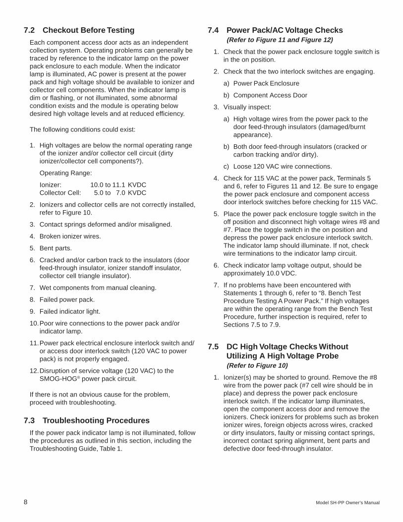
7.2 Checkout Before Testing
Each component access door acts as an independentcollection system. Operating problems can generally betraced by reference to the indicator lamp on the powerpack enclosure to each module. When the indicatorlamp is illuminated, AC power is present at the powerpack and high voltage should be available to ionizer andcollector cell components. When the indicator lamp isdim or flashing, or not illuminated, some abnormalcondition exists and the module is operating belowdesired high voltage levels and at reduced efficiency.
The following conditions could exist:
1. High voltages are below the normal operating rangeof the ionizer and/or collector cell circuit (dirtyionizer/collector cell components?).
Operating Range:
Ionizer: 10.0 to 11.1 KVDCCollector Cell: 5.0 to 7.0 KVDC
2. Ionizers and collector cells are not correctly installed,refer to Figure 10.
3. Contact springs deformed and/or misaligned.
4. Broken ionizer wires.
5. Bent parts.
6. Cracked and/or carbon track to the insulators (doorfeed-through insulator, ionizer standoff insulator,collector cell triangle insulator).
7. Wet components from manual cleaning.
8. Failed power pack.
9. Failed indicator light.
10.Poor wire connections to the power pack and/orindicator lamp.
11.Power pack electrical enclosure interlock switch and/or access door interlock switch (120 VAC to powerpack) is not properly engaged.
12.Disruption of service voltage (120 VAC) to theSMOG-HOG® power pack circuit.
If there is not an obvious cause for the problem,proceed with troubleshooting.
7.3 Troubleshooting Procedures
If the power pack indicator lamp is not illuminated, followthe procedures as outlined in this section, including theTroubleshooting Guide, Table 1.
7.4 Power Pack/AC Voltage Checks(Refer to Figure 11 and Figure 12)
1. Check that the power pack enclosure toggle switch isin the on position.
2. Check that the two interlock switches are engaging.
a) Power Pack Enclosure
b) Component Access Door
3. Visually inspect:
a) High voltage wires from the power pack to thedoor feed-through insulators (damaged/burntappearance).
b) Both door feed-through insulators (cracked orcarbon tracking and/or dirty).
c) Loose 120 VAC wire connections.
4. Check for 115 VAC at the power pack, Terminals 5and 6, refer to Figures 11 and 12. Be sure to engagethe power pack enclosure and component accessdoor interlock switches before checking for 115 VAC.
5. Place the power pack enclosure toggle switch in theoff position and disconnect high voltage wires #8 and#7. Place the toggle switch in the on position anddepress the power pack enclosure interlock switch.The indicator lamp should illuminate. If not, checkwire terminations to the indicator lamp circuit.
6. Check indicator lamp voltage output, should beapproximately 10.0 VDC.
7. If no problems have been encountered withStatements 1 through 6, refer to “8. Bench TestProcedure Testing A Power Pack.” If high voltagesare within the operating range from the Bench TestProcedure, further inspection is required, refer toSections 7.5 to 7.9.
7.5 DC High Voltage Checks WithoutUtilizing A High Voltage Probe(Refer to Figure 10)
1. Ionizer(s) may be shorted to ground. Remove the #8wire from the power pack (#7 cell wire should be inplace) and depress the power pack enclosureinterlock switch. If the indicator lamp illuminates,open the component access door and remove theionizers. Check ionizers for problems such as brokenionizer wires, foreign objects across wires, crackedor dirty insulators, faulty or missing contact springs,incorrect contact spring alignment, bent parts anddefective door feed-through insulator.

Model SH-PP Owner’s Manual 9
2. Cell(s) may be shorted. With #8 wire in place,remove #7 wire from the power pack and depressthe power pack enclosure interlock switch. If theindicator lamp illuminates, open the componentaccess door and check the collection cells. Removethe cells and check for contaminant bridging acrossthe plates or to the cabinet structure. Check forproper plate-to-plate clearance, spring contact,buildup on or tracking across triangular insulators,bent plates and the condition of door feed-throughinsulator.
7.6 Measuring for High Voltage (DC Only)
To correctly check power pack high voltage output, ahigh voltage probe with a scale from 0 to 15 KVDC isnecessary, refer to manufacturer’s instructions for properusage.
7.7 Check Ionizers (Refer to Figure 10 and 13)
1. Make sure the component access door is closed andthat ionizers and contact springs/contact screws arein place and correctly connected. Check that thetoggle switch is in the on position.
2. Open the power pack access door and connect theground wire of the high voltage probe to any baremetal grounded surface.
3. Depress power pack enclosure door interlock switch.
4. Place tip of probe to the ionizer door feed-throughinsulator. Ionizer voltage should read 10.0 to 11.1KVDC with the indicator lamp illuminated.
5. If the ionizer voltage is low, open component accessdoor and check for a voltage at the contact washer tothe ionizer door feed-through insulator of 10.0 to11.1 KVDC. If voltage is still low, refer to “PowerPack/AC Voltage Check.” If not, the problem is withinthe ionizer components, broken wire, bridged orcracked standoff insulators, refer to Section 8,“Bench Test Procedure” for checking ionizercomponents.
7.8 Checking Collection Cells(Refer to Figure 10 and 13)
1. To measure high voltage to the collection cells, usesame procedure as described above for ionizers,except at the cell door feed-through insulator.
2. Cell voltage should read 5.0 to 7.0 KVDC withindicator lamp illuminated.
3. Refer to Section 8, “Bench Testing Procedure ForChecking Collector Cell Components.”
7.9 Indicator Lamp
If satisfactory ionizer/cell voltage is present and thelamp remains off, the problem can be a defective lamp,lamp circuit wiring or an internal problem within thepower pack.
The LED indicator lamp located on the power packenclosure is polarity sensitive. For proper operation, the“+” (gold) terminal on the lamp must be connected toTerminal 9 of the power pack. If the lamp wires arereversed, the lamp will not light.
Power Pack Indicator Lamp Output with the LEDconnected is approximately 10.0 VDC.
Power Pack Indicator Lamp Outlet with a 6Vincandescent lamp is approximately 3.5 to 6.0 VDC.

10 Model SH-PP Owner’s Manual
TAB
LE
1 -
TR
OU
BL
ES
HO
OT
ING
GU
IDE
PR
OB
LE
MC
AU
SE
SO
LU
TIO
N
Blin
king
indi
cato
r la
mp
to th
e po
wer
pac
k1.
Exc
essi
ve c
onta
min
ant b
uild
up in
the
ioni
zer
1.Is
olat
e pr
oble
m, r
efer
to S
ectio
ns 7
.5 to
7.8
.en
clos
ure,
con
tinuo
us c
licki
ng/s
napp
ing
nois
e.an
d/or
col
lect
or c
ell c
ompo
nent
s ca
usin
gar
cing
.2.
Impr
oper
com
pone
nt e
lect
rical
alig
nmen
t.2.
Ref
er to
Fig
ure
10.
3.B
ent/d
efor
med
/war
ped
cell
plat
es.
3.C
aref
ully
str
aigh
ten
cell
plat
es.
4.B
ent i
oniz
er p
arts
.4.
Rep
lace
ben
t par
ts.
5.D
efor
med
ioni
zer
and/
or c
olle
ctor
cel
l con
tact
5.R
epla
ce c
onta
ct s
prin
gs.
sprin
gs.
6.C
rack
ed a
nd/o
r ca
rbon
trac
ked
insu
lato
rs;
6.V
isua
lly in
spec
t all
insu
lato
rs a
nd r
epla
cedo
or fe
ed-t
hrou
gh in
sula
tors
, ion
izer
sta
ndof
ffa
iled
insu
lato
rs (
carb
on tr
ack
is a
bla
ckis
hin
sula
tors
, cel
l tria
ngle
insu
lato
r.st
reak
em
bedd
ed in
to th
e su
rfac
e).
7.B
roke
n io
nize
r w
ires.
7.R
epla
ce io
nize
r w
ires.
8.Io
nize
rs a
nd c
olle
ctor
cel
l com
pone
nts
are
wet
8.P
lace
togg
le s
witc
h in
the
off p
ositi
on to
eac
haf
ter
man
ual c
lean
ing.
pow
er p
ack
encl
osur
e an
d op
erat
e th
e sy
stem
exha
ust b
low
er u
ntil
com
pone
nts
are
dry,
appr
oxim
atel
y 30
min
utes
.
Indi
cato
r la
mp
fails
to il
lum
inat
e.1.
Ref
er to
blin
king
indi
cato
r la
mp
Sta
tem
ents
1.R
efer
to b
linki
ng in
dica
tor
lam
p S
tate
men
ts1
thro
ugh
8.1
thro
ugh
8.2.
No
120
VA
C to
the
pow
er p
ack.
2.C
heck
eng
agem
ent o
f pow
er p
ack
and
com
pone
nt a
cces
s do
or in
terlo
ck s
witc
hes.
Che
ck fo
r loo
se w
ire te
rmin
atio
ns, b
roke
n w
ires.
3.P
ower
pac
k fa
ilure
.3.
Ref
er to
Sec
tion
7.4.
4.In
dica
tor
lam
p fa
ilure
.4.
Ref
er to
Sec
tion
7.9.
His
sing
noi
se to
the
ioni
zer
com
pone
nts.
1.Lo
ose
ioni
zer
wire
s.1.
Che
ck io
nize
r w
ire s
prin
gs a
nd io
nize
rw
ire ta
utne
ss.
2.Lo
ose
ioni
zer
supp
ort b
ar.
2.T
ight
en w
ire s
uppo
rt b
ar.
3.B
ent p
arts
to th
e io
nize
r.3.
Rep
lace
ben
t par
ts.
4.Io
nize
r w
ires
coat
ed w
ith c
onta
min
ant.
4.C
lean
ioni
zer
wire
s.5.
Cra
cked
or
dirt
y in
sula
tors
.5.
Cle
an o
r re
plac
e in
sula
tor,
ioni
zer
stan
doff
insu
lato
rs, i
oniz
er/c
olle
ctor
cel
l doo
r fe
ed-
thro
ugh
insu
lato
r.
Sys
tem
is n
ot c
lean
ing
the
airs
trea
m.
1.Im
prop
er c
ompo
nent
ele
ctric
al a
lignm
ent.
1.R
efer
to F
igur
e 10
.2.
Mea
sure
hig
h vo
ltage
s. O
pera
ting
Ran
geIo
nize
r: 1
0.0
to 1
1.1
KV
DC
. Col
lect
or C
ell:
5.0
to 7
.0 K
VD
C. M
anua
lly c
lean
com
pone
nts
ifbe
low
the
oper
atin
g ra
nge.
Rep
lace
faile
dpo
wer
pac
ks. F
or te
stin
g, r
efer
to S
ectio
n 7.
4.
Can
not p
lace
sys
tem
on-
line.
1.C
ircui
t bre
aker
trip
ped/
fuse
s fa
iled.
1.R
esto
re p
ower
by
rese
tting
the
circ
uit
brea
ker/
repl
acin
g fu
ses.

Model SH-PP Owner’s Manual 11
8. BENCH TEST PROCEDURETHE FOLLOWING IS FOR THE USE OF TRAINEDPERSONNEL ONLY
This procedure can be utilized to determine an electricalproblem with a power pack or an ionizer/collection cellbefore or after manually cleaning.
TOOLS REQUIRED
• One power pack.
• Two high voltage wires (or spark plug wire), 6' inlength with test clips at each end of wire.
• One high voltage probe.
• One AC cord to activate power pack, 120 VAC, withground wire.
HIGH VOLTAGE OPERATING RANGE
Ionizer Section: 10.0 to 11.1 KVDCCollector Cell Section: 5.0 to 7.0 KVDC
PROCEDURE (Refer to Figure 12)
TESTING AN IONIZER
1. Select one ionizer component to be tested.
2. Connect one high voltage wire to ionizer contactspring and to power pack connector identified as“ionizer.”
3. Connect the other high voltage wire to metal frameof the ionizer and to the ground stud on the powerpack. This serves as a ground.
4. AC cord should be connected to power pack withground wire secured to ground stud on the powerpack.
5. Connect AC cord plug to wall outlet.
6. Measure high voltage with probe, ionizer voltageshould be about 10.0 to 11.1 KVDC.
7. Disconnect AC cord plug from wall outlet.
8. Discharge high voltage with a screwdriver withplastic handle by touching the ionizer wire with theblade of a screwdriver and contacting screwdrivershaft to metal frame.
Possible causes for below normal ionizer high voltages:
Ionizers: Dirty components (requires manual cleaning),bent parts, broken ionizer wires, cracked or carbon trackstandoff insulators, deformed contact spring groundingto an adjacent ionizer, wet ionizer from washing.
TESTING A COLLECTOR CELL
The cell can be tested in the same manner as an ionizerwith the following exceptions:
• Step 1 – Select one collector cell to be tested.
• Step 2 – Connect high voltage wire to power packconnector, identified as “collector” and to cell contactspring.
• Step 3 – Connect the other high voltage wire to themetal frame of the collector cell and to the groundstud on the power pack.
• Step 6 – Cell voltage should be 5.0 to 7.0 KVDC.
• Step 8 – Discharge high voltage by inserting ascrewdriver blade between cell plates.
Possible causes for below normal cell voltages:
Collector Cell: Dirty components (requires manualcleaning), warped/deformed/bent cell plates, contaminantbridging between the cell plates, deformed cell contactspring grounding to an adjacent collector cell, wetcollector cell from washing.
TESTING A POWER PACK
1. Perform Steps 4 and 5.
2. Measure high voltage with probe.
Ionizer Operating Range: 10.0 to 11.1 KVDCCollector Cell Operating Range: 5.0 to 7.0 KVDC
3. Replace power pack if high voltages are below theoperating range.
! C AU T I O NHazardous live and moving parts are exposed duringthe following procedures. Switch off/isolate theelectrical supply to the SMOG-HOG® Air CleaningSystem before servicing.
! C AU T I O NRisk of electrical shock. A residual DC voltage willremain on high voltage components for a short timeafter power is removed. Prior to handling, groundcomponents using an insulated screwdriver, refer toFigures 2 and 3.

12 Model SH-PP Owner’s Manual
9. STANDARD PART REPLACEMENTPROCEDURES
9.1 Ionizer Wires (See Figure 14)
1. Remove damaged wire from each spring.
2. Replace spring if damaged or missing.
3. Loop one end of new wire over bottom spring. Pulltop spring down with pliers and loop end of wire overspring.
4. Release spring gently. Wire should now be taut andcentered.
NOTE: IF REPLACEMENT WIRES ARE NOTAVAILABLE, REMOVE BROKEN WIRES AND/OR SPRINGS FROM THE ASSEMBLY UNTILPARTS ARE AVAILABLE. OPERATION WITHMISSING IONIZER WIRES WILL RESULT INREDUCED OPERATING EFFICIENCY.
9.2 Door Feed-Through Insulator
1. Turn toggle switch to the “off” position.
2. Open power pack access door.
3. Remove lead wire by removing both #10-32 hexnuts.
4. Remove insulator retaining nut.
5. Open component access door and remove defectiveinsulator.
6. Remove long screw from insulator.
7. Clean RTV sealant from door surface.
8. Install replacement insulator, reversing the aboveprocedure, making sure to apply a thin coat ofsealant (RTV) to base insulator.
! C AU T I O NWhen the system is operating, 115 VAC is present inthis enclosure even with the toggle switch in the offposition.
9.3 Component Access Door Gasket
1. Remove existing door gasket making sure to removeall contaminant residue.
2. Trim one edge of the new door gasket neatly andevenly.
3. Measure and cut gasket to approximate lengthrequired, allowing surplus for final trim.
4. Install the trimmed edge at the top center cabinetdoor flange. Use a small mallet to tap the gasket onthe four-sided cabinet flange.
5. Check that the door gasket is firmly seated onto thecabinet door flange. If the door gasket is not firmlyseated, the door gasket may not seal.

Model SH-PP Owner’s Manual 13
9.4 SH-PP Replacement Parts List
Part Number Description
* 02-7012-S Ionizer Assembly, 9 Wire
* 02-3267 Ionizer Wires, 15 mil (9 per set)
* 03-0558 Springs for Ionizer Wires (18 per set)
* 36-0009 Ionizer Contact Spring (short length)
* 36-0016 Ionizer Contact Spring (long length)
* 02-1303 Contact Nut Assembly
* 37-0028 Ionizer Standoff Insulator (convoluted)
* 02-2339-S GPN Collector Cell
* 36-0009 Cell Contact Spring
* 30-0387 Cell Contact Screw
* 30-0394 Cell Flat Washer #8
* 33-0001 Pre/Afterfilters (Aluminum) 18 x 18-3/8 x 7/8
* 21-1248 Power Pack
03-1497 High Voltage Wire Kit for Ionizer and Collector Cell
37-0026 Door Feed-Through Insulator
02-0749 Door Feed-Through Insulator Assembly (includes 37-0026 Insulator)
20-2748 LED (Green) Indicator Lamp
02-0331 Indicator Lamp Assembly 6V Incandescent Red Lens
20-0258 Lamp Socket for 02-0331
20-0260 Lens, Red for 02-0331
20-0467 Bulb, Incandescent 6V for 02-0331
20-0326 Toggle Switch - SPST, 125V
20-0035 Rubber Boot for Toggle Switch
20-2907 Interlock Switch
42-1530 Component Access Door Gasket (7 ft. required for each access door)
* Recommended Spare Parts (Quantity: 2 of each, with the exception of the power pack which requires only one.)

14 Model SH-PP Owner’s Manual
10. ORDERING PARTS
10.1 Replacement Parts
Replacement parts for ionizers, collection cells andmiscellaneous parts identified in Section 9.4. Othercommon replacement parts can be identified ondrawings shipped with the system.
To order UAS parts, contact your local representative orcall/write:
United Air Specialists, Inc.4440 Creek Road
Cincinnati, Ohio 45242Tel. 1-800-252-4647
For prompt service, please specify:
1. Unit Model Number (nameplate)
2. Part Number or Part Description (refer to Section 9.4)
10.2 Returning Parts
When returning parts directly to UAS for any reason,call UAS for a return material authorization number(RMA). Mark this number prominently on the returnedpackage to assure prompt handling and service.
10.3 Freight Cost
Freight cost on returned parts must be paid by thesender. Freight cost on parts shipped from UAS isprepaid by UAS and added to the cost of the parts.
Model SH-PP Owner’s Manual 15
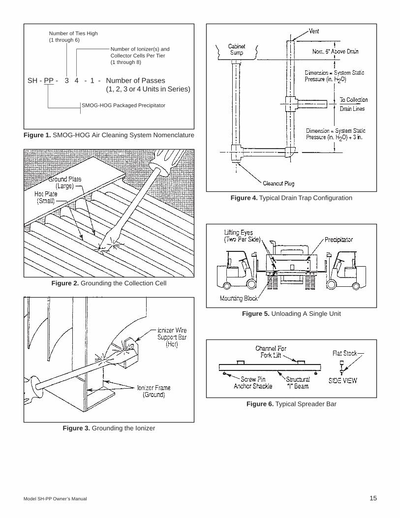
Figure 1. SMOG-HOG Air Cleaning System Nomenclature
SH - PP - 3 4 - 1 - Number of Passes(1, 2, 3 or 4 Units in Series)
Number of Ties High(1 through 6)
Number of Ionizer(s) andCollector Cells Per Tier(1 through 8)
SMOG-HOG Packaged Precipitator
Figure 2. Grounding the Collection Cell
Figure 3. Grounding the Ionizer
Figure 4. Typical Drain Trap Configuration
Figure 5. Unloading A Single Unit
Figure 6. Typical Spreader Bar

16 Model SH-PP Owner’s Manual
Figure 7. Lifting SMOG-HOG Modular Unit
Figure 8. Lifting Loose Pieces
Figure 9. Suggested Corner Gasket

Model SH-PP Owner’s Manual 17
Figure 10. Installation of Ionizer & Collector Cell Components

18 Model SH-PP Owner’s Manual
Figure 11. Label, Wiring Diagram - SH-PP
Figure 12. H.V. Power Supply Input/Output Connections
Figure 13. Ionizer and Cell Voltage Measurement withAccess Door Closed
Figure 14. Ionizer Wire Replacement
Figure 15. Wiring Diagram


UNITED AIR SPECIALISTS, INC.LIMITED WARRANTY
UAS warrants all equipment manufactured and sold by UAS against defective parts and workmanship for oneyear from date of shipment to Purchaser, except that commercial or non-industrial air cleaners (other thanengineered systems) are warranted for three years from such date. This warranty is subject to the limitations inUAS’ standard terms and conditions provided to Purchaser. Any unauthorized repairs or modifications or ab-normal use or misuse of equipment will void all warranties. In no case will UAS’ responsibility or warrantyextend to equipment not manufactured by UAS.
THE FOREGOING WARRANTY IS EXCLUSIVE AND IN LIEU OF ALL OTHER WARRANTIES,WHETHER WRITTEN, ORAL OR IMPLIED, INCLUDING ANY IMPLIED WARRANTY OF MERCHANT-ABILITY, FITNESS FOR A PARTICULAR PURPOSE OR NONINFRINGEMENT.
As Purchasers exclusive remedy for any defects in the equipment, UAS will exchange or repair any defectiveparts during the warranty period, provided such parts are returned, prepaid, to UAS’ factory. The obligation ofUAS is limited to furnishing replacement parts F.O.B. UAS’ factory or making repairs at UAS’ factory of anyparts which are determined, upon inspection by UAS, to be defective. UAS is not responsible for labor ortransportation charges for the removal, reshipment or reinstallation of the parts.
IN NO EVENT WILL UAS BE RESPONSIBLE FOR ANY SPECIAL OR CONSEQUENTIAL DAMAGES.
4440 Creek Road • Cincinnati, Ohio 45242National: (800) 252-4647
Telephone: (513) 891-0400 • Fax: (513) 891-4882http://www.uasinc.com
An ISO Certified Company
ISO 4.1.11 10/01Part No. 44-10199-0001