smia 1.0 part 6: reliability...
TRANSCRIPT

SMIA 1.0 Part 6: Reliability
Specification
Nokia & ST Confidential

SMIA 1.0 Part 6: Reliability specification
DISCLAIMER The contents of this document are copyright © 2004 Nokia Corporation, ST Microelectronics NV and their licensors. All rights reserved. You may not copy, modify nor distribute this document without prior written consent by Nokia and ST. No license to any Nokia’s, ST’s or their licensor’s intellectual property rights are granted herein. YOU ACKNOWLEDGE THAT THIS SMIA SPECIFICATION IS PROVIDED "AS IS" AND NEITHER NOKIA, ST NOR THEIR LICENSORS MAKE ANY REPRESENTATIONS OR WARRANTIES, EXPRESS OR IMPLIED, INCLUDING BUT NOT LIMITED TO THE WARRANTIES OF MERCHANTABILITY OR FITNESS FOR A PARTICULAR PURPOSE OR THAT THIS SMIA SPECIFICATION OR ANY PRODUCT, SOFTWARE APPLICATION OR SERVICE IMPLEMENTING THIS SMIA SPECIFICATION WILL NOT INFRINGE ANY THIRD PARTY PATENTS, COPYRIGHTS, TRADEMARKS OR OTHER RIGHTS. THERE IS NO WARRANTY BY NOKIA, ST OR BY ANY OTHER PARTY THAT THE FUNCTIONS CONTAINED IN THIS SMIA SPECIFICATION WILL MEET YOUR REQUIREMENTS. LIMITATION OF LIABILITY. IN NO EVENT SHALL NOKIA, ST OR THEIR EMPLOYEES, LICENSORS OR AGENTS BE LIABLE FOR ANY LOST PROFITS OR COSTS OF PROCUREMENT OF SUBSTITUTE GOODS OR SERVICES, PROPERTY DAMAGE, PERSONAL INJURY, LOSS OF PROFITS, INTERRUPTION OF BUSINESS OR FOR ANY SPECIAL, INDIRECT, INCIDENTAL, ECONOMIC, COVER, PUNITIVE, OR CONSEQUENTIAL DAMAGES, HOWEVER CAUSED AND WHETHER ARISING UNDER CONTRACT, TORT, NEGLIGENCE, OR OTHER THEORY OF LIABILITY ARISING OUT OF THIS SMIA SPECIFICATION, EVEN IF NOKIA, ST OR THEIR LICENSORS ARE ADVISED OF THE POSSIBILITY OF SUCH DAMAGES. IN THE EVENT THAT ANY EXCLUSION CONTAINED HEREIN SHALL BE HELD TO BE INVALID FOR ANY REASON AND NOKIA, ST OR THEIR LICENSORS BECOMES LIABLE FOR LOSS OR DAMAGE THAT MAY LAWFULLY BE LIMITED, SUCH LIABILITY SHALL BE LIMITED TO U.S.$50. Specifications mentioned in this publication are subject to change without notice. This document supersedes and replaces all versions previously supplied.
Nokia & ST Confidential Page ii of 21

SMIA 1.0 Part 6: Reliability specification
History
Version Date Author Status Notes
1.0 30-June-2004 Nokia and ST Approved
Nokia & ST Confidential Page iii of 21

SMIA 1.0 Part 6: Reliability specification
Table of contents
1. Overview ........................................................................................................................8 1.1 Objective........................................................................................................................................ 8 1.2 Scope of Application...................................................................................................................... 8
2. General Requirements..................................................................................................8 2.1 Performance Measurements ......................................................................................................... 8 2.2 Standard Measurement Environment ........................................................................................... 8 2.3 Measurement System Analysis ..................................................................................................... 8 2.4 Test Data Availability..................................................................................................................... 9 2.5 Requalification Requirements ....................................................................................................... 9
3. Test Classification ......................................................................................................10 3.1 Lot Acceptance Tests (Group A) ................................................................................................. 10 3.2 Reliability Monitoring Tests (Group B) ........................................................................................ 10 3.3 Research & Development Level Tests (Group C)....................................................................... 10 3.4 Mechanical Tests for Connection Systems (Group D)................................................................ 10 3.5 Tests for Changes ....................................................................................................................... 11
4. Test Requirements......................................................................................................11 4.1 Group A Tests (Lot Acceptance Tests for camera module)........................................................ 11
4.1.1 A1, Electrical Characteristics............................................................................................... 11 4.1.2 A2, Mechanical Characteristics ........................................................................................... 11 4.1.3 A3, Optical Characteristics .................................................................................................. 11 4.1.4 A4, Shipping Packages and Labels..................................................................................... 11
4.2 Group B Tests (Reliability Monitoring Tests for camera module) ............................................... 11 4.2.1 B1, High Temperature Operating Life Test / Early Life Failure Rate Estimation................. 11 4.2.2 B2, Temperature & Humidity Stress Test............................................................................ 12 4.2.3 B2.3 Mechanical Impact Tests ............................................................................................ 14
4.3 Group C Tests (R&D Tests for camera module) ......................................................................... 15 4.3.1 C1: Do B1 Test Again.......................................................................................................... 15 4.3.2 C2: Combination Test; Test B2 + (B2.2 and B2.3).............................................................. 15 4.3.3 C3: High Temperature ......................................................................................................... 15 4.3.4 C4; Random Vibration ......................................................................................................... 15 4.3.5 C5: Latch Up Test................................................................................................................ 16 4.3.6 C6 Steady State Temperature Humidity Bias Life Test....................................................... 16 4.3.7 C7 High Temperature Operating Life Test .......................................................................... 17 4.3.8 C8 Low Temperature Operating Life Test ........................................................................... 17 4.3.9 C9 Solar Radiation Test ...................................................................................................... 17
4.4 Group D Tests: Mechanical Tests for Connection Systems (Connectors & FPC)...................... 18 4.4.1 D1 Vibration Tests ............................................................................................................... 18 4.4.2 D2 Pull-Out Test (Camera Module from the Socket In case Applicable) ............................ 19 4.4.3 D3 Peel-Out Test of the FPC (in Case Applicable) ............................................................. 19 4.4.4 D4 Module Insertion Test .................................................................................................... 19 4.4.5 D5 Flex Bending Test .......................................................................................................... 19 4.4.6 D6 Connector Quality Check............................................................................................... 19 4.4.7 D7 Mechanical Impact Tests ............................................................................................... 20
5. References...................................................................................................................21 5.1 IEC Standards ............................................................................................................................. 21 5.2 JEDEC Standards ....................................................................................................................... 21
Nokia & ST Confidential Page iv of 21
SMIA 1.0 Part 6: Reliability specification
List of tables Table 1 ECR ........................................................................................................................................... vii Table 2 Connector Quality Check.......................................................................................................... 20
Nokia & ST Confidential Page v of 21

SMIA 1.0 Part 6: Reliability specification
List of figures Figure 1 Combination Test .................................................................................................................... 13 Figure 2 Damp Heat Cycle .................................................................................................................... 14 Figure 3 Vibration Profile, Random Vibration for Module...................................................................... 16 Figure 4 Vibration Profile, Random Vibration with Connector ............................................................... 18
Nokia & ST Confidential Page vi of 21
SMIA 1.0 Part 6: Reliability specification
PREFACE Specification Supersedes Earlier Documents This document contains SMIA Reliability specification. Incorporation of Engineering Change Requests (ECRs) The following ECRs have been incorporated into this version of the specification:
ECR DESCRIPTION
Table 1 ECR
Nokia & ST Confidential Page vii of 21

SMIA 1.0 Part 6: Reliability specification
Nokia & ST Confidential
Page 8 of 21
1. Overview
1.1 Objective This document specifies minimum level qualification test requirements for SMIA camera modules. The qualification tests performed by manufacturer, shall NOT be limited by this document. Component specific requirements will be in addition to rather than instead of these requirements.
The purpose of qualification tests, which are described in this document, is to demonstrate that a component will meet the specified electrical, mechanical and optical characteristics under defined environmental conditions at the satisfactory level.
1.2 Scope of Application Test requirements described in this document are applicable to all SMIA camera modules. The document is also applicable to any possible process changes and/or material changes.
2. General Requirements For each test the new test samples are used. Notice that in the combination test (Figure 1) the same samples are used in every test step.
2.1 Performance Measurements Electrical, mechanical and/or optical characteristics must be verified / measured before and after any qualification test, according to agreed specification(s) and/or inspection plan(s). All test samples must meet the agreed specification(s) before and after each qualification test. Note for the high and/or low temperature tests: Post-test measurement shall be performed after 1.5-2 hours recovery period at standard environment.
2.2 Standard Measurement Environment Ambient for above mentioned tests (2.1) should satisfy following environment conditions.
• Temperature: 23 +/- 2 deg.C • Relative Humidity: 50 +/- 20 %RH
2.3 Measurement System Analysis All test systems and/or inspection systems, which are used for electrical, mechanical and optical characteristics measurement, shall be calibrated and verified its capability with Gauge R&R study

SMIA 1.0 Part 6: Reliability specification
Nokia & ST Confidential
Page 9 of 21
(using ANOVA method) prior to use. All measurement systems must satisfy following capability for Gauge R&R study.
• %Contribution: Maximum 15% • %Tolerance: Maximum 30%
2.4 Test Data Availability All qualification test data shall be stored at test performing company, according to manufacturer’s own document control guideline(s). Any qualification test data shall be available to customer upon its request.
2.5 Requalification Requirements Detailed requalification requirements must be agreed between the manufacturer and the customer. This affects items 3.1, 3.2 and 4.2.1. Any reliability plan agreed between the supplier and the customer supersedes the requirements from the Re-qualification procedure.

SMIA 1.0 Part 6: Reliability specification
Nokia & ST Confidential
Page 10 of 21
3. Test Classification
3.1 Lot Acceptance Tests (Group A) Group A tests are classified as the minimum requirements for the Outgoing Inspection at camera module manufacturer premises, i.e. a final quality assurance inspection prior to the shipment. Group A tests shall be performed every lot based on statistically meaningful sampling plan. Sampling size and acceptance criteria shall be determined according to the internationally recognized standard(s) such as IEC410 or equivalent. Preferable AQL level < 0.65% Level S-2
Note: Group A test shall be managed by Quality Assurance, not by Manufacturing.
3.2 Reliability Monitoring Tests (Group B) Group B tests are classified as the minimum requirements for the Reliability Monitoring Tests at camera module manufacturer. The purpose of Group B tests is to maintain conformance of component against the required reliability level, and to collect the data of failure rate & failure modes. The average failure rate should be calculated, in terms of FIT (i.e. Failure In Time), as a running mean value over one year period. FIT value should be used in order to estimate the failure rate at normal temperature (i.e. 23 +/- 2 deg.C). Group B tests shall be performed at least quarterly, unless specified separately. Additionally Group B tests shall be performed by monthly basis for first three (3) months from its ramp up.
3.3 Research & Development Level Tests (Group C) Group C tests are classified as the minimum requirements for R & D testing. This test phase is the widest of these test types. The purpose of Group C test is to verify conformance of component reliability and functionality according to the agreed specification between the customer and the supplier. Group C tests shall be performed for every new sub-module and/or new processes. The sampling size should be more than 30 pcs for each test, otherwise specified separately. Additionally, camera performance tests form a subset of the acceptance criteria for R&D level testing. The full set includes functional, interface, power and characterization testing and will be performed typically by the customer. Camera module manufacturer is responsible for performing group C testing. Tests are performed to the new camera module versions and/or new processes.
3.4 Mechanical Tests for Connection Systems (Group D) Test responsible company is connector manufacturer or customer. In case connector manufacturer is doing tests, then camera modules can be dummy or daisy chain samples with full mechanical performance. Tests are performed to new connection system versions or changes in qualified versions.
SMIA 1.0 Part 6: Reliability specification
Nokia & ST Confidential
Page 11 of 21
3.5 Tests for Changes Tests are classified as the minimum requirements for “Change Management” against any changes of materials, manufacturing and/or inspection processes. The purpose of tests is to verify the conformance of the component reliability and functionality according to the agreed specification between the customer and the supplier. These tests are same as 3.3 or 3.4 in the case of changes in the connection systems. Note: Camera module manufacturer is responsible for the verification of the changes at sub-suppliers and /or subcontractors
4. Test Requirements
4.1 Group A Tests (Lot Acceptance Tests for camera module)
4.1.1 A1, Electrical Characteristics • All electrical characteristics, which are defined in the agreed component specification, shall be
tested according to statistically meaningful sampling plan.
4.1.2 A2, Mechanical Characteristics • All mechanical characteristics, which are defined in the agreed component specification, shall
be tested according to statistically meaningful sampling plan.
4.1.3 A3, Optical Characteristics • All optical characteristics, which are defined in the agreed component specification, shall be
tested according to statistically meaningful sampling plan.
4.1.4 A4, Shipping Packages and Labels • Shipping package shall be compliant with customer logistics system.
4.2 Group B Tests (Reliability Monitoring Tests for camera module)
4.2.1 B1, High Temperature Operating Life Test / Early Life Failure Rate Estimation • The purpose of B1 test is to determine the effects of the bias condition and the temperature on
a sensor chip over the time. The average failure rate should be calculated in terms of FIT as a running mean value. Test samples, i.e. sensor chip, shall be assembled in prompt test package such as CLCC (i.e. Ceramic Leaded Chip Carrier).
• Test Temperature: 125 +/- 5 deg.C • Test Duration: 48 hours • Bias: Maximum operating voltage specified for the device • Sampling Size: Minimum 50 pcs

SMIA 1.0 Part 6: Reliability specification
Nokia & ST Confidential
Page 12 of 21
• References: JESD22-A108-B, JESD47-A and JESD74
4.2.2 B2, Temperature & Humidity Stress Test • The purpose of B2 series tests is to examine the mechanical integrity of each part under
defined stress conditions. These three tests, i.e. B2.1-2.3, shall be performed as a serial test using same samples. (See Figure 1. B2 combination Test Diagram). Any failures shall not be accepted. Any failures detected shall be reported immediately with written failure analysis. Test samples shall be tested in its non-operating mode. Sample size shall be more than 30 pcs or statistically meaningful number.
SMIA 1.0 Part 6: Reliability specification
Nokia & ST Confidential
Page 13 of 21
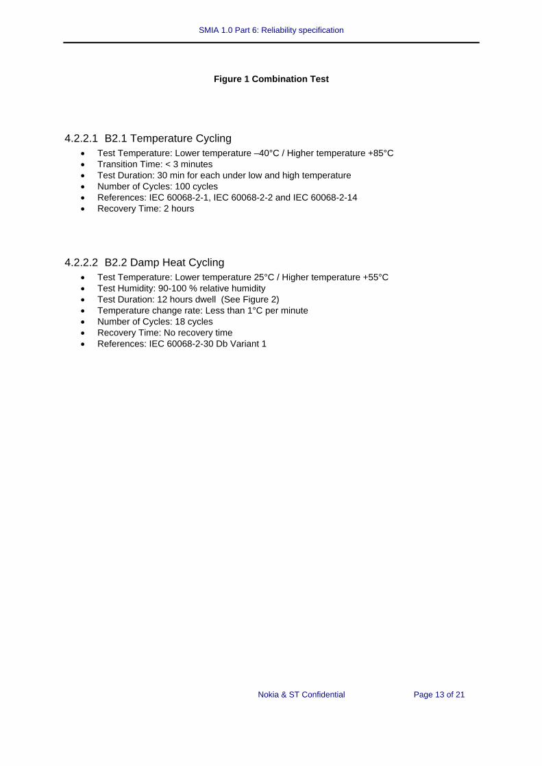
Figure 1 Combination Test
4.2.2.1 B2.1 Temperature Cycling • Test Temperature: Lower temperature –40°C / Higher temperature +85°C • Transition Time: < 3 minutes • Test Duration: 30 min for each under low and high temperature • Number of Cycles: 100 cycles • References: IEC 60068-2-1, IEC 60068-2-2 and IEC 60068-2-14 • Recovery Time: 2 hours
4.2.2.2 B2.2 Damp Heat Cycling • Test Temperature: Lower temperature 25°C / Higher temperature +55°C • Test Humidity: 90-100 % relative humidity • Test Duration: 12 hours dwell (See Figure 2) • Temperature change rate: Less than 1°C per minute • Number of Cycles: 18 cycles • Recovery Time: No recovery time • References: IEC 60068-2-30 Db Variant 1

SMIA 1.0 Part 6: Reliability specification
Nokia & ST Confidential
Page 14 of 21
Figure 2 Damp Heat Cycle
4.2.3 B2.3 Mechanical Impact Tests • Shock test is part of combination test when test is done by camera module manufacturer.
4.2.3.1 B2.3.1 Shock Test • G-value: 1500g 1mS Duration • Number of drops: 5 pulses in each of the orientations X1 X2, Y1 Y2, Z1 Z2. 30 pulses in all.
Test equipment: Suitable Shock Tower or equivalent • Reference: JESD22 B104-A/B

SMIA 1.0 Part 6: Reliability specification
Nokia & ST Confidential
Page 15 of 21
4.3 Group C Tests (R&D Tests for camera module)
4.3.1 C1: Do B1 Test Again
4.3.2 C2: Combination Test; Test B2 + (B2.2 and B2.3)
4.3.3 C3: High Temperature The purpose of C3 test is to examine the effect to camera modules, which is caused by exposing to the high temperature ambient. Test samples shall be tested in its non-operating mode.
• Test temperature: Static 85 +/- 2 deg.C • Test humidity: Less than 20 g/m3 of water vapour (corresponding approximately 50%RH at 35
deg.C) • Test duration: 168 hours • Temp. change rate: Less than 1 deg.C per minute • Sample size: Minimum 10 pcs • Reference: IEC 60068-2-2 Bb
4.3.4 C4; Random Vibration This test is performed to identify possible dust problem inside a module.
• Vibration profile: 5 – 10 Hz: + 10 dB / octave, 10 – 50 Hz: 5.58 m² / s³ (0.0558 g² / Hz), 50 – 300 Hz: - 10 dB / octave (See Figure 3)
• Test duration: 3 x 20 min for three perpendicular directions (X, Y and Z) • Sample size: Min 10 pcs • Reference: IEC 60068-2-64 Fh

SMIA 1.0 Part 6: Reliability specification
Nokia & ST Confidential
Page 16 of 21
Figure 3 Vibration Profile, Random Vibration for Module
4.3.5 C5: Latch Up Test The purpose of C5 test is to verify latch up characteristics of CMOS sensor. Latch up characteristics are extremely important in determining component reliability and minimizing No Failure Found (NFF) and Electrical Over Stress (EOS) failures due to latch up.
• Test temperature: 25 +/- 2 deg.C • Vsupply Condition: Maximum operating voltage for each Vsupply pin group per device specification • Trigger test condition
• I-Test (positive): Inominal + 100 mA or 1.5 x Inominal • I-Test (negative): -100 mA or –0.5 x Inominal • Over voltage test: 1.5 x max. Vsupply (Inominal + 100 mA or 1.5 x Inominal)
• Sample size: Minimum 6 pcs • Reference: JESD78
4.3.6 C6 Steady State Temperature Humidity Bias Life Test The purpose of C6 test is to determine the effects of bias under humid condition on sensor chip over time. Test samples, i.e. sensor chip, shall be assembled in prompt test package such as CLCC (i.e. Ceramic Leaded Chip Carrier).
• Test Temperature: 85 +/- 2 deg.C • Test Humidity: 85 +/- 5 %RH • Test Duration: 1000 hours (interim inspections required at the points of 168 & 504 hours) • Bias: Maximum operating voltage specified for the device

SMIA 1.0 Part 6: Reliability specification
Nokia & ST Confidential
Page 17 of 21
• Sample Size: min 50 pcs • Reference: JESD22-A101-B
4.3.7 C7 High Temperature Operating Life Test The purpose of C7 test is to determine the effects of bias condition and temperature on sensor chip over time. The average failure rate should be calculated in terms of FIT as a running mean value. Test samples, i.e. sensor chip, shall be assembled in prompt test package such as CLCC (i.e. Ceramic Leaded Chip Carrier).
• Test Temperature: 125 +/- 5 deg.C • Test Duration: 1000 hours (interim inspections required at the points of 168 & 504 hours) • Bias: Maximum operating voltage specified for the device • Sample Size: min 50 pcs • References: JESD22-A108-B, JESD47-A and JESD74
4.3.8 C8 Low Temperature Operating Life Test The purpose of C8 test is to determine the effects of bias condition and temperature on sensor chip over time. The average failure rate should be calculated in terms of FIT as a running mean value. Test samples, i.e. sensor chip, shall be assembled in prompt test package such as CLCC (i.e. Ceramic Leaded Chip Carrier).
• Test Temperature: -30 +/- 5 deg. C • Test Duration: 240 hours • Bias: Maximum operating voltage specified for the device • Sample Size: min 50 pcs • References: JESD22-A108-B, JESD47-A
4.3.9 C9 Solar Radiation Test The purpose of C9 test is to verify the effects of solar radiation exposure to the camera modules, especially to lens and IR glass. Test samples shall be tested in its non-operating mode.
• Test Temperature: 55 deg.C during irradiation cycle, 25 deg.C during dark cycle • Irradiance: 1120 W/m2 • Test Duration: 8 hours for irradiation and 16 hours for darkness (= 1 cycle) • Number of cycles: 10 cycles • Sample Size: Minimum 10 pcs • References: IEC 60068-2-5 Sa, Procedure A

SMIA 1.0 Part 6: Reliability specification
Nokia & ST Confidential
Page 18 of 21
4.4 Group D Tests: Mechanical Tests for Connection Systems (Connectors & FPC) Mechanical tests are performed to study the mechanical functionality of the whole mechanical construction. These tests are focused on socket and connector testing. The most of these test demands all components attached together. These tests are performed by customer or connection system manufacturer.
4.4.1 D1 Vibration Tests • For socket + connector spring + camera module system with power on to check the electrical
functionality of connection system. During test functionality is followed by using module video image. Contact failures are not allowed.
• Sample amount 1+1+1 pieces
4.4.1.1 D1.1 Random Vibration EUT Power On • Vibration profile: 5 – 10 Hz + 10 dB / octave, 10 – 50 Hz 5.58 m² / s³ (0.0558 g² / Hz), 50 – 300
Hz - 10 dB / octave (See Figure 4) • Test duration: 3 x 20 min for three perpendicular directions (X, Y and Z) • Reference: IEC 60068-2-64 Fh
Figure 4 Vibration Profile, Random Vibration with Connector

SMIA 1.0 Part 6: Reliability specification
Nokia & ST Confidential
Page 19 of 21
4.4.1.2 D1.2 Bumb Vibration EUT Power On • Bump profile: 80 m / s² (peak); 20 ms, half cycle sinusoidal • Test duration: 3 x 2000 pulses for three perpendicular directions (X, Y and Z) • Reference: IEC 60068-2-29 Eb
4.4.2 D2 Pull-Out Test (Camera Module from the Socket In case Applicable) Pull-out force for the module to detach it from the holder is measured by material tester. Pull out strength is measured and informed. Sample size min 5 pcs.
4.4.3 D3 Peel-Out Test of the FPC (in Case Applicable) Peel-out force for the FPC to detach from module is measured by material tester. Test is performed also after B2 test. Results are compared to see possible degradation of adhesive bonding between module and flex. Sample size min 5 pcs.
4.4.4 D4 Module Insertion Test To assure functionality of camera module and socket under field use insertion test is needed. 10 pcs of new camera modules and sockets are tested. Assembly and removal tools must be used. Test passing criteria is 5 insertions and removals without fault, including metallization.
4.4.5 D5 Flex Bending Test If camera is attached to product by using moving parts so that also flex is under move, flex bending durability must be tested. Flex is bended back and forth over the maximum moving area until failure happens. Number of bending cycles is measured and informed. Sample size min 10 pcs.
4.4.6 D6 Connector Quality Check Connectors, especially compression connectors, have a remarkable influence on reliability. Therefore some general properties of connectors are found out. As a pre-check suitability of spring geometry (shape and smoothness of contact area) from wearing point of view is checked. Sharp edges and coating pinholes are not allowed.
Test no
Name of the test Description

SMIA 1.0 Part 6: Reliability specification
Nokia & ST Confidential
Page 20 of 21
1 Coating thickness measurement for spring contact areas
Coating thickness is measured and informed.
2 Wearing test Visual inspection after testing
Wearing between pad and spring contact areas are followed in test B2. No serious wearing (through gold plating) and no corrosion is allowed during test.
Camera connection pads
Test no
Name of a test Description
1 Coating thickness measurement for PWB.
Coating thickness is measured and informed.
Table 2 Connector Quality Check
4.4.7 D7 Mechanical Impact Tests
4.4.7.1 Free Fall Test for Module + Socket (Including Connector) • Height of fall: 1.5 m • Number of drops: 2 drops for each 6 faces for 1st 10pcs • Test surface: A smooth, hard and rigid surface of concrete or polished stone • Test jig: Test samples shall be mounted on a phone mechanics or equivalent test jig. • Reference: IEC 60068-2-32 - procedure1, SMIA mechanics test jig specification
4.4.7.2 Free Fall Repeated Test for Module + Socket (Including Connector) • Height of fall: 1.0m • Number of drops: 300 (random drop direction) • Test equipment: Tumble tester • Reference: IEC 60068-2-32 - procedure 2, SMIA mechanics test jig specification

SMIA 1.0 Part 6: Reliability specification
Nokia & ST Confidential
Page 21 of 21
5. References
5.1 IEC Standards • IEC 60068-2-1: Test Ab Cold • IEC 60068-2-2: Test Bb Dry Heat • IEC 60068-2-5: Test Sa Simulated solar radiation at ground level • IEC 60068-2-6: Test Fc Vibration (sinusoidal) • IEC 60068-2-14: Test Na Change of Temperature • IEC 60068-2-29: Test: Eb Bump • IEC 60068-2-30: Test Db and guidance Damp heat, cyclic • IEC 60068-2-32: Test Ed Free Fall • IEC 60068-2-64: Test Fh Vibration, broad-band random (digital control) and guidance • IEC 61000-4-2: Electromagnetic Compatibility – Testing and measurement techniques -
Electrostatic discharge immunity test
5.2 JEDEC Standards • JESD22-A101-B: Steady State Temperature Humidity Bias Life Test • JESD22-A102-B: Accelerated Moisture Resistance – Unbiased Autoclave • JESD22-A104-B: Temperature Cycling • JESD22-A108-B: Temperature, Bias, and Operation Life • JESD22-A113-B: Preconditioning of Non-hermetic Surface Mount Devices Prior to Reliability
Testing • JESD22-A114-B: Electrostatic Discharge (ESD) Sensitivity Testing Human Body Model (HBM) • JESD46: Guidelines for User Notification of Product/Process Changes By Semiconductor
Suppliers • JESD47-A: Stress-Test-Driven Qualification of Integrated Circuit • JESD74: Early Life Failure Rate Calculation Procedure for Electronic Components • JESD78: IC Latch-Up Test