smartax ma5633 d-ccap head end device · pdf filehuawei smartax ma5633 distributed converged...
TRANSCRIPT
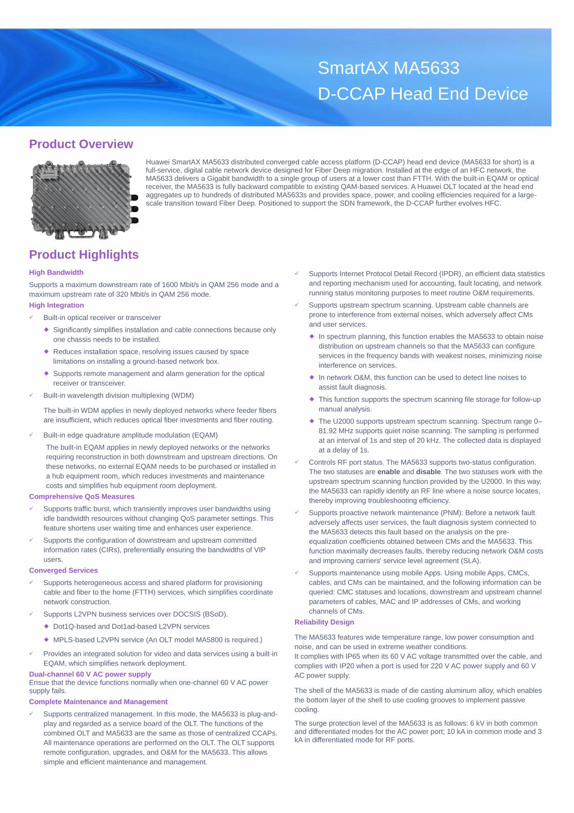
Product Overview
Huawei SmartAX MA5633 distributed converged cable access platform (D-CCAP) head end device (MA5633 for short) is a full-service, digital cable network device designed for Fiber Deep migration. Installed at the edge of an HFC network, the MA5633 delivers a Gigabit bandwidth to a single group of users at a lower cost than FTTH. With the built-in EQAM or optical receiver, the MA5633 is fully backward compatible to existing QAM-based services. A Huawei OLT located at the head end aggregates up to hundreds of distributed MA5633s and provides space, power, and cooling efficiencies required for a large-scale transition toward Fiber Deep. Positioned to support the SDN framework, the D-CCAP further evolves HFC.
Product Highlights
High Bandwidth
Supports a maximum downstream rate of 1600 Mbit/s in QAM 256 mode and a
maximum upstream rate of 320 Mbit/s in QAM 256 mode.
High Integration
Built-in optical receiver or transceiver
Significantly simplifies installation and cable connections because only
one chassis needs to be installed.
Reduces installation space, resolving issues caused by space
limitations on installing a ground-based network box.
Supports remote management and alarm generation for the optical
receiver or transceiver.
Built-in wavelength division multiplexing (WDM)
The built-in WDM applies in newly deployed networks where feeder fibers
are insufficient, which reduces optical fiber investments and fiber routing.
Built-in edge quadrature amplitude modulation (EQAM)
The built-in EQAM applies in newly deployed networks or the networks
requiring reconstruction in both downstream and upstream directions. On
these networks, no external EQAM needs to be purchased or installed in
a hub equipment room, which reduces investments and maintenance
costs and simplifies hub equipment room deployment.
Comprehensive QoS Measures
Supports traffic burst, which transiently improves user bandwidths using
idle bandwidth resources without changing QoS parameter settings. This
feature shortens user waiting time and enhances user experience.
Supports the configuration of downstream and upstream committed
information rates (CIRs), preferentially ensuring the bandwidths of VIP
users.
Converged Services
Supports heterogeneous access and shared platform for provisioning
cable and fiber to the home (FTTH) services, which simplifies coordinate
network construction.
Supports L2VPN business services over DOCSIS (BSoD).
Dot1Q-based and Dot1ad-based L2VPN services
MPLS-based L2VPN service (An OLT model MA5800 is required.)
Provides an integrated solution for video and data services using a built-in
EQAM, which simplifies network deployment.
Dual-channel 60 V AC power supply Ensue that the device functions normally when one-channel 60 V AC power supply fails.
Complete Maintenance and Management
Supports centralized management. In this mode, the MA5633 is plug-and-
play and regarded as a service board of the OLT. The functions of the
combined OLT and MA5633 are the same as those of centralized CCAPs.
All maintenance operations are performed on the OLT. The OLT supports
remote configuration, upgrades, and O&M for the MA5633. This allows
simple and efficient maintenance and management.
Supports Internet Protocol Detail Record (IPDR), an efficient data statistics
and reporting mechanism used for accounting, fault locating, and network
running status monitoring purposes to meet routine O&M requirements.
Supports upstream spectrum scanning. Upstream cable channels are
prone to interference from external noises, which adversely affect CMs
and user services.
In spectrum planning, this function enables the MA5633 to obtain noise
distribution on upstream channels so that the MA5633 can configure
services in the frequency bands with weakest noises, minimizing noise
interference on services.
In network O&M, this function can be used to detect line noises to
assist fault diagnosis.
This function supports the spectrum scanning file storage for follow-up
manual analysis.
The U2000 supports upstream spectrum scanning. Spectrum range 0–
81.92 MHz supports quiet noise scanning. The sampling is performed
at an interval of 1s and step of 20 kHz. The collected data is displayed
at a delay of 1s.
Controls RF port status. The MA5633 supports two-status configuration.
The two statuses are enable and disable. The two statuses work with the
upstream spectrum scanning function provided by the U2000. In this way,
the MA5633 can rapidly identify an RF line where a noise source locates,
thereby improving troubleshooting efficiency.
Supports proactive network maintenance (PNM): Before a network fault
adversely affects user services, the fault diagnosis system connected to
the MA5633 detects this fault based on the analysis on the pre-
equalization coefficients obtained between CMs and the MA5633. This
function maximally decreases faults, thereby reducing network O&M costs
and improving carriers' service level agreement (SLA).
Supports maintenance using mobile Apps. Using mobile Apps, CMCs,
cables, and CMs can be maintained, and the following information can be
queried: CMC statuses and locations, downstream and upstream channel
parameters of cables, MAC and IP addresses of CMs, and working
channels of CMs.
Reliability Design
The MA5633 features wide temperature range, low power consumption and
noise, and can be used in extreme weather conditions.
It complies with IP65 when its 60 V AC voltage transmitted over the cable, and
complies with IP20 when a port is used for 220 V AC power supply and 60 V
AC power supply.
The shell of the MA5633 is made of die casting aluminum alloy, which enables
the bottom layer of the shell to use cooling grooves to implement passive
cooling.
The surge protection level of the MA5633 is as follows: 6 kV in both common and differentiated modes for the AC power port; 10 kA in common mode and 3 kA in differentiated mode for RF ports.
SmartAX MA5633
D-CCAP Head End Device
Application Scenarios
Provides the HSI, VoD, CATV, and dynamic voice services for residential users to meet multiple service operators (MSOs)' service requirements.
Provides the L2VPN BSoD service for enterprise users.
Provides the WLAN hotspot backhaul service using APs.
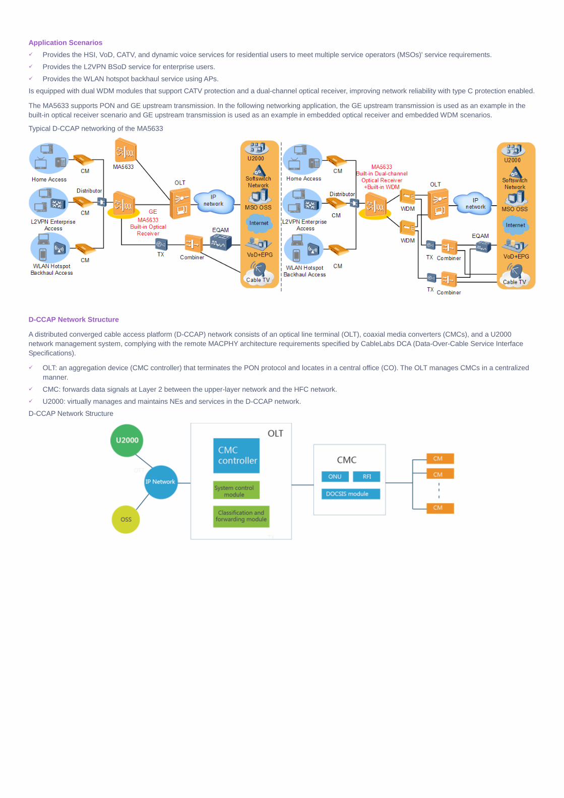
Is equipped with dual WDM modules that support CATV protection and a dual-channel optical receiver, improving network reliability with type C protection enabled.
The MA5633 supports PON and GE upstream transmission. In the following networking application, the GE upstream transmission is used as an example in the
built-in optical receiver scenario and GE upstream transmission is used as an example in embedded optical receiver and embedded WDM scenarios.
Typical D-CCAP networking of the MA5633
D-CCAP Network Structure
A distributed converged cable access platform (D-CCAP) network consists of an optical line terminal (OLT), coaxial media converters (CMCs), and a U2000
network management system, complying with the remote MACPHY architecture requirements specified by CableLabs DCA (Data-Over-Cable Service Interface
Specifications).
OLT: an aggregation device (CMC controller) that terminates the PON protocol and locates in a central office (CO). The OLT manages CMCs in a centralized
manner.
CMC: forwards data signals at Layer 2 between the upper-layer network and the HFC network.
U2000: virtually manages and maintains NEs and services in the D-CCAP network.
D-CCAP Network Structure
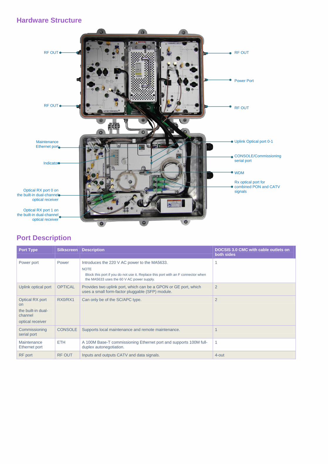
Hardware Structure
Maintenance
Ethernet port
Uplink Optical port 0-1
Power Port
CONSOLE/Commissioning
serial port
WDM
Optical RX port 0 on
the built-in dual-channel
optical receiver
Indicator
RF OUT
RF OUT
RF OUT
RF OUT
Optical RX port 1 on
the built-in dual-channel
optical receiver
Rx optical port for
combined PON and CATV
signals
Port Description
Port Type Silkscreen Description DOCSIS 3.0 CMC with cable outlets on both sides
Power port Power Introduces the 220 V AC power to the MA5633.
NOTE
Block this port if you do not use it. Replace this port with an F connector when
the MA5633 uses the 60 V AC power supply.
1
Uplink optical port OPTICAL Provides two uplink port, which can be a GPON or GE port, which uses a small form-factor pluggable (SFP) module.
2
Optical RX port on
the built-in dual-channel
optical receiver
RX0/RX1 Can only be of the SC/APC type. 2
Commissioning serial port
CONSOLE Supports local maintenance and remote maintenance. 1
Maintenance Ethernet port
ETH A 100M Base-T commissioning Ethernet port and supports 100M full-duplex autonegotiation.
1
RF port RF OUT Inputs and outputs CATV and data signals. 4-out
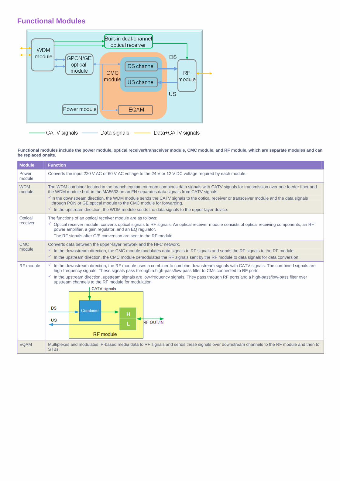
Functional Modules
Functional modules include the power module, optical receiver/transceiver module, CMC module, and RF module, which are separate modules and can be replaced onsite.
Module Function
Power module
Converts the input 220 V AC or 60 V AC voltage to the 24 V or 12 V DC voltage required by each module.
WDM module
The WDM combiner located in the branch equipment room combines data signals with CATV signals for transmission over one feeder fiber and the WDM module built in the MA5633 on an FN separates data signals from CATV signals.
In the downstream direction, the WDM module sends the CATV signals to the optical receiver or transceiver module and the data signals through PON or GE optical module to the CMC module for forwarding.
In the upstream direction, the WDM module sends the data signals to the upper-layer device.
Optical receiver
The functions of an optical receiver module are as follows:
Optical receiver module: converts optical signals to RF signals. An optical receiver module consists of optical receiving components, an RF power amplifier, a gain regulator, and an EQ regulator.
The RF signals after O/E conversion are sent to the RF module.
CMC module
Converts data between the upper-layer network and the HFC network.
In the downstream direction, the CMC module modulates data signals to RF signals and sends the RF signals to the RF module.
In the upstream direction, the CMC module demodulates the RF signals sent by the RF module to data signals for data conversion.
RF module In the downstream direction, the RF module uses a combiner to combine downstream signals with CATV signals. The combined signals are high-frequency signals. These signals pass through a high-pass/low-pass filter to CMs connected to RF ports.
In the upstream direction, upstream signals are low-frequency signals. They pass through RF ports and a high-pass/low-pass filter over upstream channels to the RF module for modulation.
EQAM Multiplexes and modulates IP-based media data to RF signals and sends these signals over downstream channels to the RF module and then to STBs.

Block Diagram (with a Built-in Optical Receiver)
In the preceding figure,
Black lines indicate power cable connections.
Brown lines indicate downstream transmission, upstream transmission, and CATV connections.
RF ports are of SMB type.
CMC Module Specifications
GPON Upstream Transmission
Description Notes
Standards compliance ITU-T G.984
Port type SC/UPC
TX rate 1.244 Gbit/s
RX rate 2.488 Gbit/s
TX wavelength 1310 nm
RX wavelength 1490 nm
Minimum TX optical power 0.5 dBm
Maximum TX optical power 5 dBm
RX sensitivity –27 dBm
Overload optical power –8 dBm
Transmission distance 20 km
Performance Parameter of the Integrated Device
Description Notes
Maximum throughput Downstream: 1600 Mbit/s@256 QAM
Upstream: 320 Mbit/s@256 QAM
1 and 2
Number of supported service flows 4000 in both downstream and upstream directions
Number of concurrent online CMs 1023 DOCSIS 3.0-compliant CMs
System reliability specifications System availability for the typical configuration: > 99.999%
Mean time between failures (MTBF): about 35 years.
3
Notes:
1: The rate is obtained at the PHY layer.
2: The test is performed under the condition of 32 downstream channels (8 MHz per channel) and 8 upstream channels (6.4 MHz per channel).
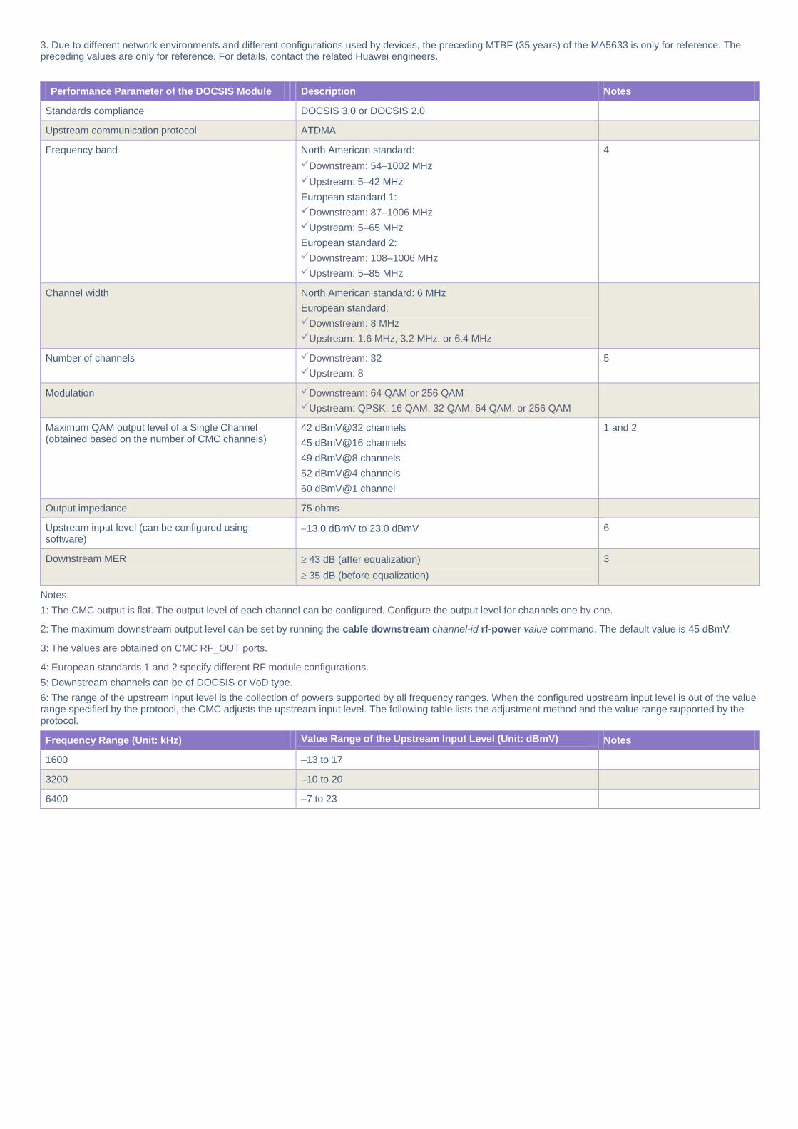
3. Due to different network environments and different configurations used by devices, the preceding MTBF (35 years) of the MA5633 is only for reference. The preceding values are only for reference. For details, contact the related Huawei engineers.
Performance Parameter of the DOCSIS Module
Description Notes
Standards compliance DOCSIS 3.0 or DOCSIS 2.0
Upstream communication protocol ATDMA
Frequency band North American standard:
Downstream: 541002 MHz
Upstream: 542 MHz
European standard 1:
Downstream: 87–1006 MHz
Upstream: 5–65 MHz
European standard 2:
Downstream: 108–1006 MHz
Upstream: 5–85 MHz
4
Channel width North American standard: 6 MHz
European standard:
Downstream: 8 MHz
Upstream: 1.6 MHz, 3.2 MHz, or 6.4 MHz
Number of channels Downstream: 32
Upstream: 8
5
Modulation Downstream: 64 QAM or 256 QAM
Upstream: QPSK, 16 QAM, 32 QAM, 64 QAM, or 256 QAM
Maximum QAM output level of a Single Channel (obtained based on the number of CMC channels)
42 dBmV@32 channels
45 dBmV@16 channels
49 dBmV@8 channels
52 dBmV@4 channels
60 dBmV@1 channel
1 and 2
Output impedance 75 ohms
Upstream input level (can be configured using software)
13.0 dBmV to 23.0 dBmV 6
Downstream MER 43 dB (after equalization)
35 dB (before equalization)
3
Notes:
1: The CMC output is flat. The output level of each channel can be configured. Configure the output level for channels one by one.
2: The maximum downstream output level can be set by running the cable downstream channel-id rf-power value command. The default value is 45 dBmV.
3: The values are obtained on CMC RF_OUT ports.
4: European standards 1 and 2 specify different RF module configurations.
5: Downstream channels can be of DOCSIS or VoD type.
6: The range of the upstream input level is the collection of powers supported by all frequency ranges. When the configured upstream input level is out of the value range specified by the protocol, the CMC adjusts the upstream input level. The following table lists the adjustment method and the value range supported by the protocol.
Frequency Range (Unit: kHz) Value Range of the Upstream Input Level (Unit: dBmV) Notes
1600 –13 to 17
3200 –10 to 20
6400 –7 to 23
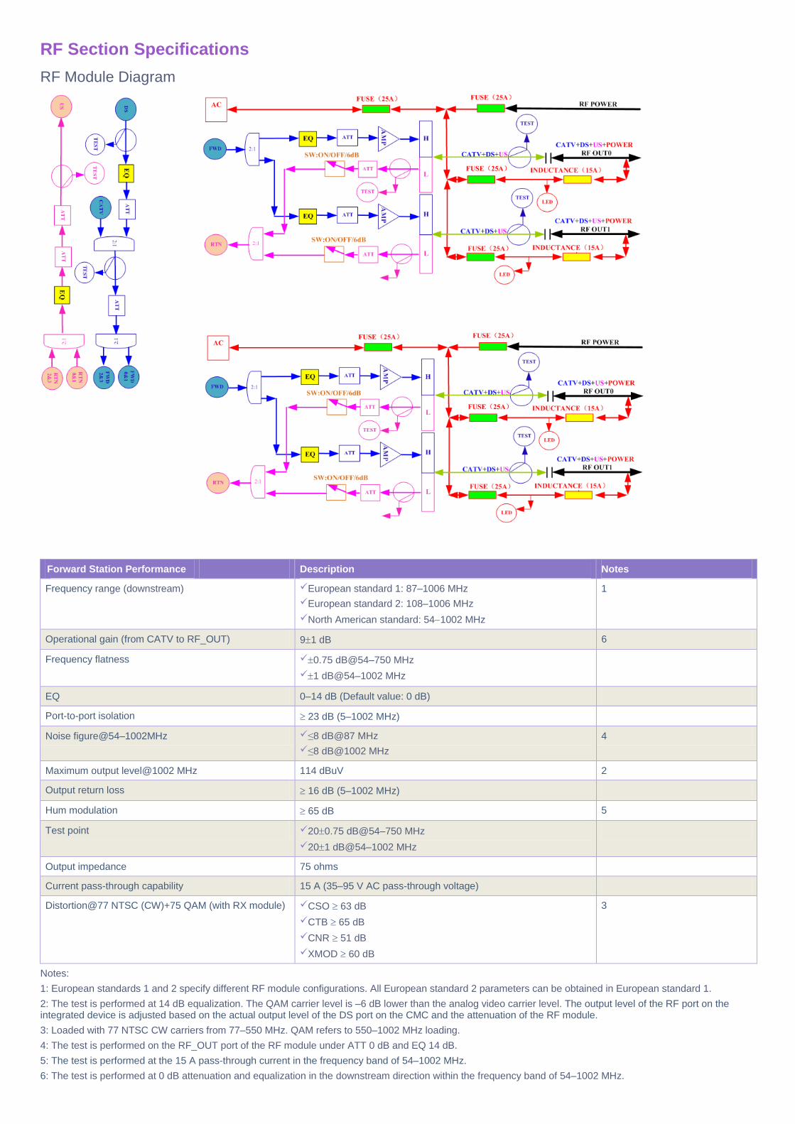
RF Section Specifications
RF Module Diagram
Forward Station Performance
Description Notes
Frequency range (downstream) European standard 1: 87–1006 MHz
European standard 2: 108–1006 MHz
North American standard: 541002 MHz
1
Operational gain (from CATV to RF_OUT) 91 dB 6
Frequency flatness 0.75 dB@54–750 MHz
1 dB@54–1002 MHz
EQ 0–14 dB (Default value: 0 dB)
Port-to-port isolation 23 dB (5–1002 MHz)
Noise figure@54–1002MHz ≤8 dB@87 MHz
≤8 dB@1002 MHz
4
Maximum output level@1002 MHz 114 dBuV 2
Output return loss 16 dB (5–1002 MHz)
Hum modulation 65 dB 5
Test point 200.75 dB@54–750 MHz
201 dB@54–1002 MHz
Output impedance 75 ohms
Current pass-through capability 15 A (35–95 V AC pass-through voltage)
Distortion@77 NTSC (CW)+75 QAM (with RX module) CSO 63 dB
CTB 65 dB
CNR 51 dB
XMOD 60 dB
3
Notes:
1: European standards 1 and 2 specify different RF module configurations. All European standard 2 parameters can be obtained in European standard 1.
2: The test is performed at 14 dB equalization. The QAM carrier level is –6 dB lower than the analog video carrier level. The output level of the RF port on the integrated device is adjusted based on the actual output level of the DS port on the CMC and the attenuation of the RF module.
3: Loaded with 77 NTSC CW carriers from 77–550 MHz. QAM refers to 550–1002 MHz loading.
4: The test is performed on the RF_OUT port of the RF module under ATT 0 dB and EQ 14 dB.
5: The test is performed at the 15 A pass-through current in the frequency band of 54–1002 MHz.
6: The test is performed at 0 dB attenuation and equalization in the downstream direction within the frequency band of 54–1002 MHz.
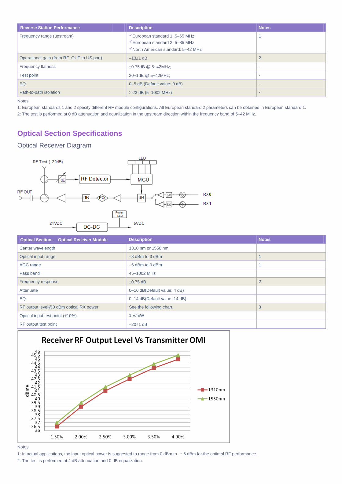
Reverse Station Performance
Description Notes
Frequency range (upstream) European standard 1: 5–65 MHz
European standard 2: 5–85 MHz
North American standard: 542 MHz
1
Operational gain (from RF_OUT to US port) –131 dB 2
Frequency flatness 0.75dB @ 5~42MHz; -
Test point 201dB @ 5~42MHz; -
EQ 0–5 dB (Default value: 0 dB) -
Path-to-path isolation 23 dB (5–1002 MHz) -
Notes:
1: European standards 1 and 2 specify different RF module configurations. All European standard 2 parameters can be obtained in European standard 1.
2: The test is performed at 0 dB attenuation and equalization in the upstream direction within the frequency band of 5–42 MHz.
Optical Section Specifications
Optical Receiver Diagram
Optical Section Optical Receiver Module
Description Notes
Center wavelength 1310 nm or 1550 nm
Optical input range –8 dBm to 3 dBm 1
AGC range –6 dBm to 0 dBm 1
Pass band 45–1002 MHz
Frequency response 0.75 dB 2
Attenuate 0–16 dB(Default value: 4 dB)
EQ 0–14 dB(Default value: 14 dB)
RF output level@0 dBm optical RX power See the following chart. 3
Optical input test point (10%) 1 V/mW
RF output test point –201 dB
Notes:
1: In actual applications, the input optical power is suggested to range from 0 dBm to –6 dBm for the optimal RF performance.
2: The test is performed at 4 dB attenuation and 0 dB equalization.
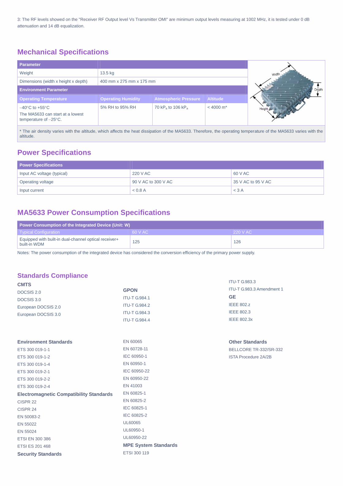
3: The RF levels showed on the "Receiver RF Output level Vs Transmitter OMI" are minimum output levels measuring at 1002 MHz, it is tested under 0 dB
attenuation and 14 dB equalization.
Mechanical Specifications
Parameter
Weight 13.5 kg
Dimensions (width x height x depth) 400 mm x 275 mm x 175 mm
Environment Parameter
Operating Temperature Operating Humidity Atmospheric Pressure Altitude
40C to +55C
The MA5633 can start at a lowest
temperature of 25C.
5% RH to 95% RH 70 kPa to 106 kPa < 4000 m*
* The air density varies with the altitude, which affects the heat dissipation of the MA5633. Therefore, the operating temperature of the MA5633 varies with the altitude.
Power Specifications
Power Specifications
Input AC voltage (typical) 220 V AC 60 V AC
Operating voltage 90 V AC to 300 V AC 35 V AC to 95 V AC
Input current < 0.8 A < 3 A
MA5633 Power Consumption Specifications
Power Consumption of the Integrated Device (Unit: W)
Typical Configuration 60 V AC 220 V AC
Equipped with built-in dual-channel optical receiver+ built-in WDM
125 126
Notes: The power consumption of the integrated device has considered the conversion efficiency of the primary power supply.
Standards Compliance
CMTS
DOCSIS 2.0
DOCSIS 3.0
European DOCSIS 2.0
European DOCSIS 3.0
GPON
ITU-T G.984.1
ITU-T G.984.2
ITU-T G.984.3
ITU-T G.984.4
ITU-T G.983.3
ITU-T G.983.3 Amendment 1
GE
IEEE 802.z
IEEE 802.3
IEEE 802.3x
Environment Standards
ETS 300 019-1-1
ETS 300 019-1-2
ETS 300 019-1-4
ETS 300 019-2-1
ETS 300 019-2-2
ETS 300 019-2-4
Electromagnetic Compatibility Standards
CISPR 22
CISPR 24
EN 50083-2
EN 55022
EN 55024
ETSI EN 300 386
ETSI ES 201 468
Security Standards
EN 60065
EN 60728-11
IEC 60950-1
EN 60950-1
IEC 60950-22
EN 60950-22
EN 41003
EN 60825-1
EN 60825-2
IEC 60825-1
IEC 60825-2
UL60065
UL60950-1
UL60950-22
MPE System Standards
ETSI 300 119
Other Standards
BELLCORE TR-332/SR-332
ISTA Procedure 2A/2B
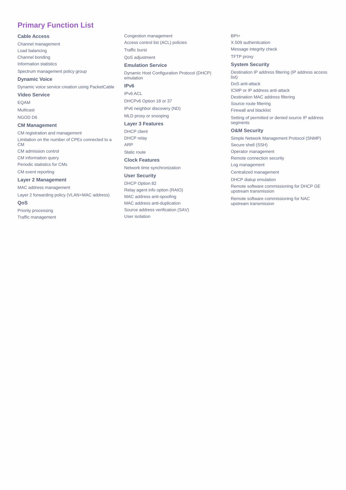
Primary Function List
Cable Access
Channel management
Load balancing
Channel bonding
Information statistics
Spectrum management policy group
Dynamic Voice
Dynamic voice service creation using PacketCable
Video Service
EQAM
Multicast
NGOD D6
CM Management
CM registration and management
Limitation on the number of CPEs connected to a CM
CM admission control
CM information query
Periodic statistics for CMs
CM event reporting
Layer 2 Management
MAC address management
Layer 2 forwarding policy (VLAN+MAC address)
QoS
Priority processing
Traffic management
Congestion management
Access control list (ACL) policies
Traffic burst
QoS adjustment
Emulation Service
Dynamic Host Configuration Protocol (DHCP) emulation
IPv6
IPv6 ACL
DHCPv6 Option 18 or 37
IPv6 neighbor discovery (ND)
MLD proxy or snooping
Layer 3 Features
DHCP client
DHCP relay
ARP
Static route
Clock Features
Network time synchronization
User Security
DHCP Option 82
Relay agent info option (RAIO)
MAC address anti-spoofing
MAC address anti-duplication
Source address verification (SAV)
User isolation
BPI+
X.509 authentication
Message integrity check
TFTP proxy
System Security
Destination IP address filtering (IP address access list)
DoS anti-attack
ICMP or IP address anti-attack
Destination MAC address filtering
Source route filtering
Firewall and blacklist
Setting of permitted or denied source IP address segments
O&M Security
Simple Network Management Protocol (SNMP)
Secure shell (SSH)
Operator management
Remote connection security
Log management
Centralized management
DHCP dialup emulation
Remote software commissioning for DHCP GE upstream transmission
Remote software commissioning for NAC upstream transmission

Issue 01, Release Date 2016-03-15
Copyright © Huawei Technologies Co., Ltd. 2016. All rights reserved. No part of this document may be reproduced or transmitted in any form or by any means without prior written consent of Huawei Technologies Co., Ltd.
Trademarks and Permissions
and other Huawei trademarks are trademarks of Huawei Technologies Co., Ltd.
All other trademarks and trade names mentioned in this document are the property of their respective holders.
Notice The purchased products, services and features are stipulated by the contract made between Huawei and the customer. All or part of the products, services and features
described in this document may not be within the purchase scope or the usage scope. Unless otherwise specified in the contract, all statements, information, and
recommendations in this document are provided "AS IS" without warranties, guarantees or representations of any kind, either express or implied.
The information in this document is subject to change without notice. Every effort has been made in the preparation of this document to ensure accuracy of the contents,
but all statements, information, and recommendations in this document do not constitute a warranty of any kind, express or implied.