smart irrigation system - simon fraser...
TRANSCRIPT

Smart Irrigation System
C-Sprinkler
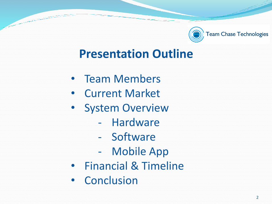
• Team Members• Current Market• System Overview
- Hardware- Software- Mobile App
• Financial & Timeline• Conclusion
Presentation Outline
2

Gray (Yu Heng) Lin- Chief Executive Officer
Chase (Youdao) Wen- President & Chief Information Officer
Team Members
3
Abel Lin- Chief Technology Officer
Yolanda Wu- Chief Operation Officer
Yuchen Wang- Chief Financial Officer
Team Members
4

What is C-Sprinkler
Smart Irrigation System- Independent AI- Remote control ability- Environment monitoring- Cloud Service
5

Functions and Features
- Traditional Features- Set timer- Direction change of sprinkler
- Smart Features- Automated irrigate- Mobile App- Multi-Clients- Environment monitoring- Reduce water usage
6

Motivation
- Internet of Things (IOT)- Popularity of mobile phones- Daily garden work
7

Market Potential
40
45
50
55
60
65
70
75
80
1996 2001 2006
% of private dwellings
owned
According to census of Canada- In 2011, 20 million people are
living in single-detached house- 2% increase in the period from
1996 till 2006- 68.4% of Canadian house holds
owns their home with 7 million households owns a single-detached house
- By 2011, this number increased to 7.3 million
8

Internet of Things- Google has spent 3.2 billion for Nest lab- Later Nest lab acquired Drop Cam for 550 million- With 3.75 billon, Google has created its own in-house
platform for Internet of things
- Apple announced HomeKit, at their developer conference in San Francisco
- HomeKit is a set of develop tools for vendors to connect their Internet of things with Apple’s ios devices
9

1. Most Basic sprinkler 2. Irrigation auto timer 3. The smart watering system
Current Competitions
10
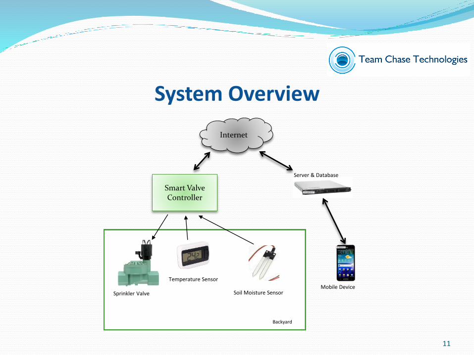
Smart Valve Controller
Internet
Sprinkler Valve
Temperature Sensor
Soil Moisture SensorMobile Device
Server & Database
Backyard
System Overview
11

Hardware
12

Hardware Overview
- Overall Functionalities - Traditional Irrigations Functionalities- Temperature and Soil Moisture- Communicate with CPU
VHDL Digital Logic
Circuitry
Valve Control
Circuitry
Sensor Circuitry
13
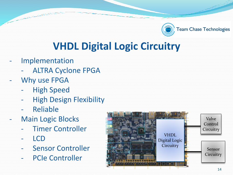
VHDL Digital Logic Circuitry- Implementation
- ALTRA Cyclone FPGA- Why use FPGA
- High Speed- High Design Flexibility- Reliable
- Main Logic Blocks- Timer Controller- LCD- Sensor Controller- PCIe Controller
VHDL Digital Logic
Circuitry
Valve Control
Circuitry
Sensor Circuitry
14
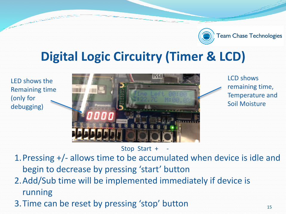
Digital Logic Circuitry (Timer & LCD)
1.Pressing +/- allows time to be accumulated when device is idle and begin to decrease by pressing ‘start’ button
2.Add/Sub time will be implemented immediately if device is running
3.Time can be reset by pressing ‘stop’ button
LED shows the Remaining time (only for debugging)
LCD shows remaining time,Temperature and Soil Moisture
Stop Start + -
15

Sensor Controller
- Functionalities- Activate the sensor
when needed- Capture and process
the sensor data based on the sensor timing and pattern
- Dispose current cycle if unexpected signals occur
16

FPGACPU Request
Ack
0
Data
PCIe Controller- Functionalities
- Synchronized changed to processor- Handshaking Process
- Follows certain rules to prevent data lose
17

Device Enclosure (Final Product)
18
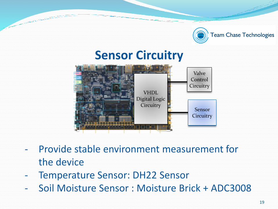
Sensor Circuitry
VHDL Digital Logic
Circuitry
Valve Control
Circuitry
Sensor Circuitry
- Provide stable environment measurement for the device
- Temperature Sensor: DH22 Sensor- Soil Moisture Sensor : Moisture Brick + ADC3008
19

Prototype Final Product
Prototype Vs Final Product
20
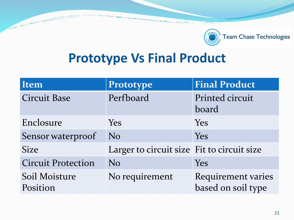
Item Prototype Final Product
Circuit Base Perfboard Printed circuitboard
Enclosure Yes Yes
Sensor waterproof No Yes
Size Larger to circuit size Fit to circuit size
Circuit Protection No Yes
Soil MoisturePosition
No requirement Requirement varies based on soil type
Prototype Vs Final Product
21
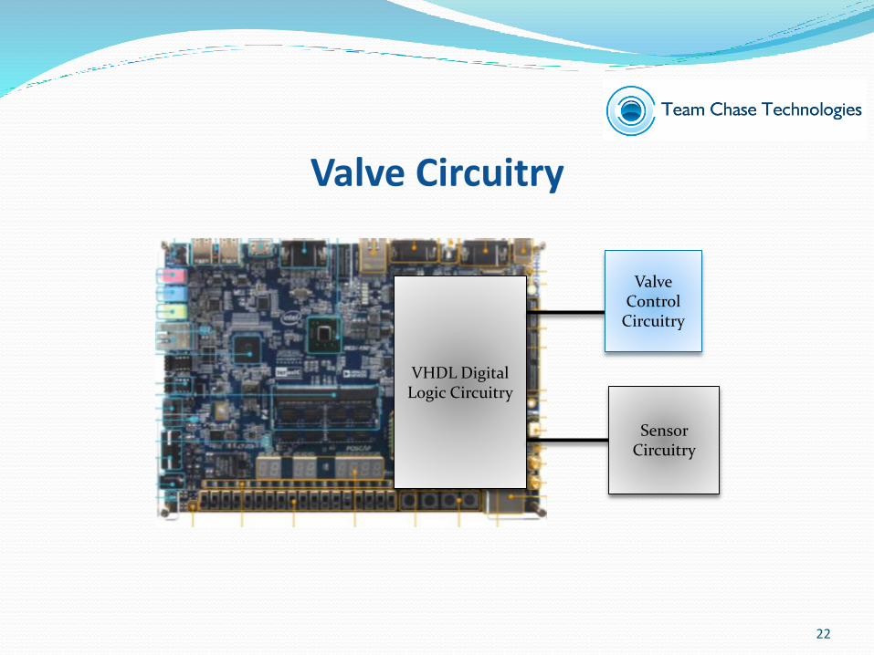
Valve Circuitry
VHDL Digital Logic Circuitry
Valve Control
Circuitry
Sensor Circuitry
22

BJTRelay
Diode
Indicator
Valve Circuitry
- Control valve power (24VAC) depends on device output (3.3 V)
- Circuit is protected from 24 VAC by- Device controls the relay by bipolar
junction transistor (BJT)- Diode protects the relay from electric
arc- Final product will assemble valve
circuitry into the device
23

Valve Circuitry
24

Software & Networking
25

cLogic – Embedded Software
- 3 Targets- Device work on itself, and no user input
required- Users can monitor device remotely, and status
update in real time- No complex set up
26

cLogic – Embedded Software
- Synchronizes with hardware- Communicates with server- Determines actions (logic)- Provides developer a debug console- Emulates the hardware while executing automation
test
27
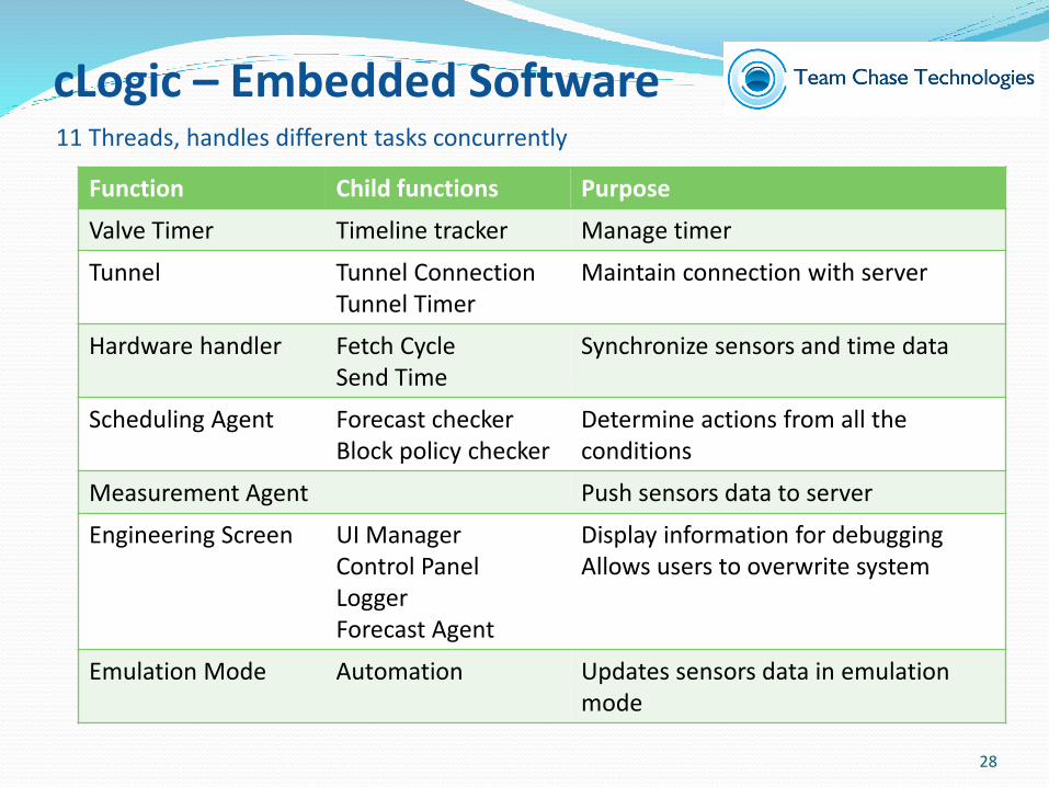
11 Threads, handles different tasks concurrently
Function Child functions Purpose
Valve Timer Timeline tracker Manage timer
Tunnel Tunnel ConnectionTunnel Timer
Maintain connection with server
Hardware handler Fetch CycleSend Time
Synchronize sensors and time data
Scheduling Agent Forecast checkerBlock policy checker
Determine actions from all the conditions
Measurement Agent Push sensors data to server
Engineering Screen UI ManagerControl PanelLoggerForecast Agent
Display information for debuggingAllows users to overwrite system
Emulation Mode Automation Updates sensors data in emulation mode
cLogic – Embedded Software
28

Real World InternetNetworking
29

Our solution: Application Overlay Network
Networking
30

Sever and Networking Architecture
Networking
31
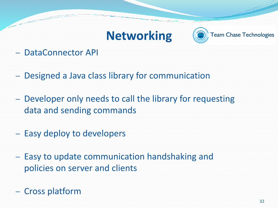
– DataConnector API
– Designed a Java class library for communication
– Developer only needs to call the library for requesting data and sending commands
– Easy deploy to developers
– Easy to update communication handshaking and policies on server and clients
– Cross platform
Networking
32

‐ Multi clients connection
‐ Amazon EC2 Cloud Services
‐ Distribute 1000 cLogic clients for our trial test with automation test cases
‐ Developed a web HTTP command line interface, and group management console, using DataConnector
‐ Debugging using logging file in automation
Networking
33

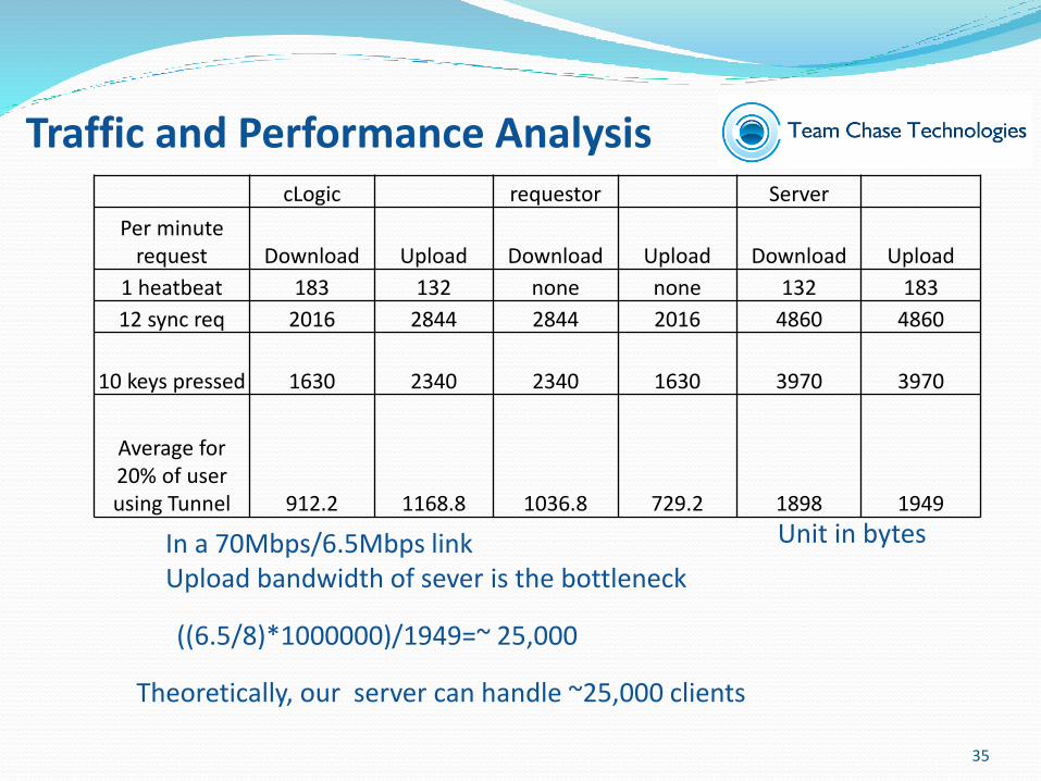
Traffic and Performance Analysis- 1 minutes heart beat message
- 183 byte from Server to Client- 132 byte from Client to Server
- Tunnel Traffics- Request status message (req) / Sync at every 5 seconds when at
request page- 168 byte from Server to Client- 237 byte from Client to Server
- Time change functions (add, sub) / When pressing control buttons- 163 byte from Server to Client- 234 byte from Client to Server
(data analyzed in wireshark) 34
cLogic requestor Server
Per minute request Download Upload Download Upload Download Upload
1 heatbeat 183 132 none none 132 183
12 sync req 2016 2844 2844 2016 4860 4860
10 keys pressed 1630 2340 2340 1630 3970 3970
Average for20% of user using Tunnel 912.2 1168.8 1036.8 729.2 1898 1949
Theoretically, our server can handle ~25,000 clients
Unit in bytesIn a 70Mbps/6.5Mbps linkUpload bandwidth of sever is the bottleneck
((6.5/8)*1000000)/1949=~ 25,000
Traffic and Performance Analysis
35

Web Graphic User Interface
36
- Currently only for debugging purpose
- Multi client control
http://cancunlab.ca/dc_test/

Mobile App
37

Mobile App: Structure
38
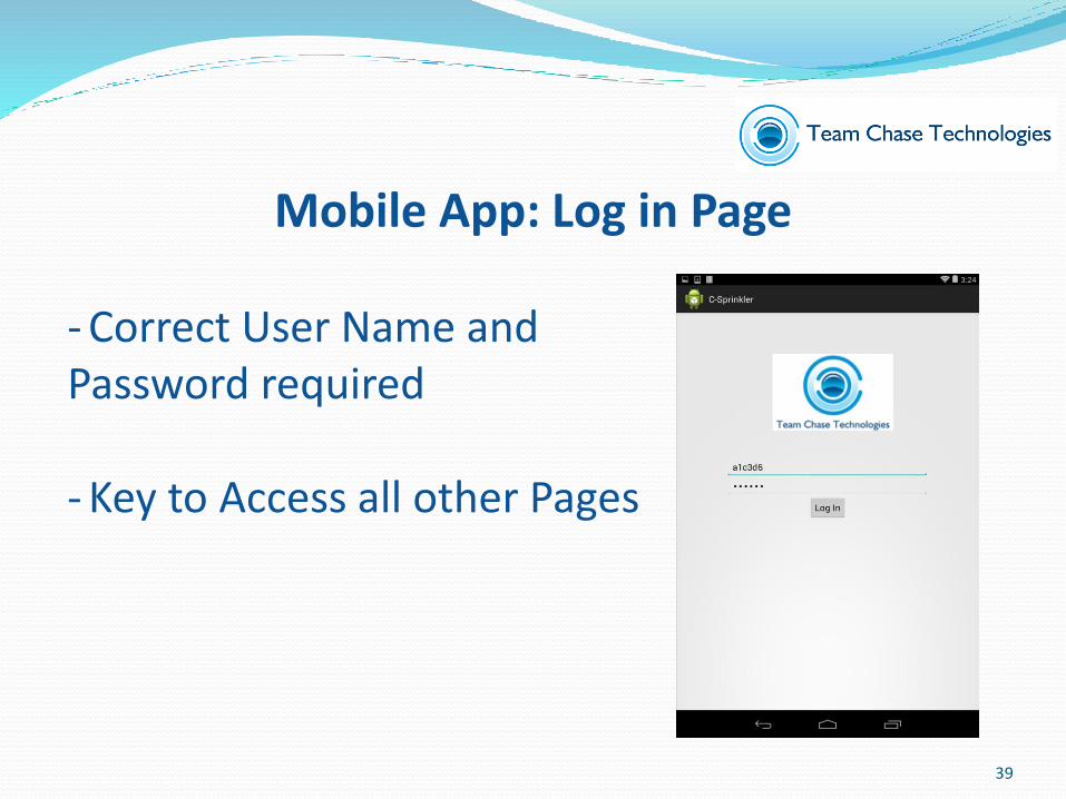
- Correct User Name and Password required
- Key to Access all other Pages
Mobile App: Log in Page
39
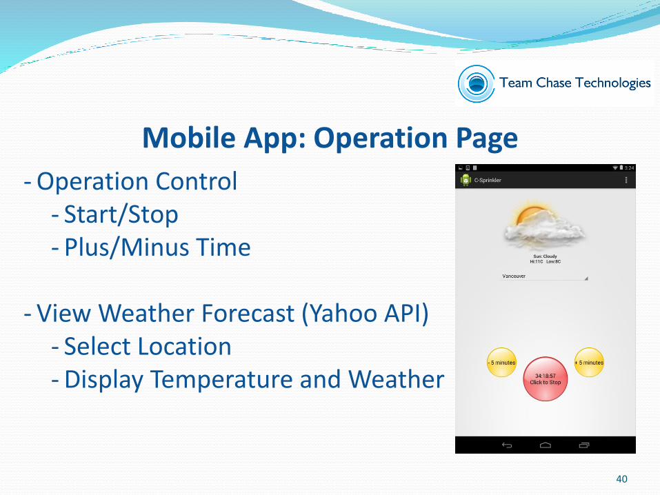
- Operation Control- Start/Stop- Plus/Minus Time
- View Weather Forecast (Yahoo API)- Select Location- Display Temperature and Weather
Mobile App: Operation Page
40

- Display Temperature Chart- Display Humidity Chart- Display Operation Time
- Clickable Calendar- Select a Day
Mobile App: History Page
41

- Block Time Modification
- Add Entries
- Remove Entries
Mobile App: Block Policy Page
42
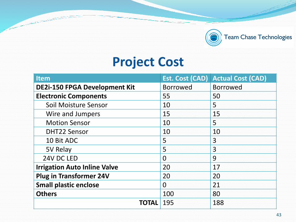
Project CostItem Est. Cost (CAD) Actual Cost (CAD)DE2i-150 FPGA Development Kit Borrowed BorrowedElectronic Components 55 50
Soil Moisture Sensor 10 5Wire and Jumpers 15 15Motion Sensor 10 5DHT22 Sensor 10 1010 Bit ADC 5 35V Relay 5 3
24V DC LED 0 9Irrigation Auto Inline Valve 20 17Plug in Transformer 24V 20 20Small plastic enclose 0 21Others 100 80
TOTAL 195 188
43
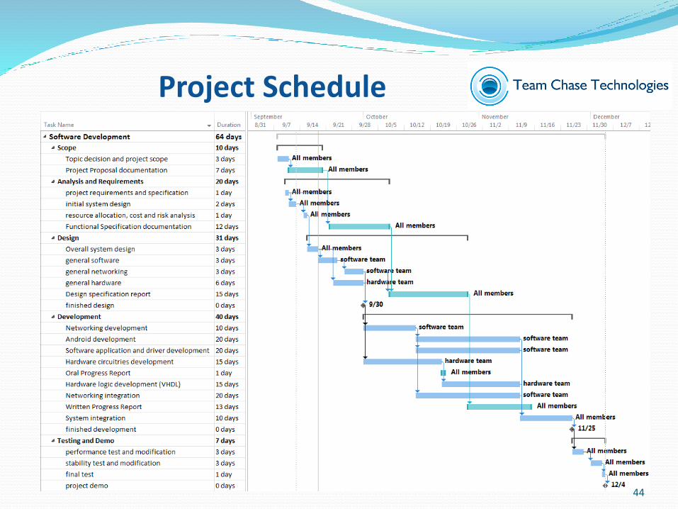
Project Schedule
44

- Better UI interface- Implement of calculation algorithm- Choice of architecture solution- Expand usage of system
Future Plan
45

- Small Company Start Up- Team Communication- PCB Design- VHDL Coding- Android App Development- Networking Optimization- QA & Integration Process
Knowledge Gained
46
- Successfully in achieving the basic functionalities in our first prototype
- Mobile app on Android platform is running
- Sensor performance is unstable which will be replaced in future
- Additional features must be implemented into final product
Summary
47

Dr. RawiczProf. WhitmoreTA – Jamal Bahari
Lukas MerhiMona Rahbar
Special Thanks
48

Reference[1] Internet of Things(IOT) (2014) TechTarget. Retrieved from http://whatis.techtarget.com/definition/Internet-of-Things[2] The Internet of Things (2014) IBM. Retrieved from http://www-01.ibm.com/software/info/Internet-of-things/[3]2006 Census Data Production (2010) Statistics Canada. Retrieved from http://www12.statcan.gc.ca/census-recensement/2006/dp-pd/92-596/P1-2.cfm?Lan%20g=eng&T=PR&PRCODE=01&GEOCODE=01&GEOLVL=PR&TID=0[4]Private households by structural type of dwelling, by prince and territory (2011 Census) (2013) Statistics Canada. Retrieved from http://www.statcan.gc.ca/tables-tableaux/sum-som/l01/cst01/famil55a-eng.htm
49

Question Period

Demo