small-scale constructed wetlands for greywater …...small-scale constructed wetlands for greywater...
TRANSCRIPT
Small-Scale Constructed Wetlands for Greywater and Total Domestic Wastewater Treatment
Version 1, March 14th, 2008
http://www.ecosanservices.org
Small-Scale Constructed Wetlands for Greywater and Total Domestic
Wastewater Treatment
Version 1, March 14th, 2008
Ecosan Training Course
“Capacity Building for Ecological Sanitation”
Compiled by Ecosan Services Foundation (ESF) and seecon gmbh in the context of the
Innovative Ecological Sanitation Network India (IESNI)

Small-Scale Constructed Wetlands for Greywater and Total Domestic Wastewater Treatment
Version 1, March 14th, 2008
http://www.ecosanservices.org
Permission is granted for the reproduction of this training material, in whole or part, for education, scientific or development related purposes except those involving commercial sale.
Ecosan Services Foundation (ESF) "Vishwa Chandra" 1002/42 Rajendra Nagar Pune – 411030, Maharashtra, India Phone/Fax: +91-(0)20-64000736 Email: [email protected] Web: http://www.ecosanservices.org
seecon gmbh Bahnhofstrasse 2 6110 Wolhusen, Switzerland Phone: +41-79-3666850 Email: [email protected] Web: http://www.seecon.ch

Small-Scale Constructed Wetlands for Greywater and Total Domestic Wastewater Treatment
Version 1, March 14th, 2008
http://www.ecosanservices.org
LIST OF CONTENT
LIST OF FIGURES ......................................................................................... V
LIST OF TABLES ........................................................................................... V
1 INTRODUCTION ............................................................................................ 1
1.1 Grey water characterisation and quantification ................................................... 1 1.2 Domestic wastewater quantification and characterisation ................................. 4
1.3 Greywater and total domestic wastewater management strageties .................. 5 1.3.1 Direct utilisation of greywater .................................................................................... 6 1.3.2 Small-scale constructed wetlands for greywater and total domestic wastewater
treatment ................................................................................................................... 8
2 SAMPLE DESIGN PROBLEM “HORIZONTAL FLOW CONSTRUCTED WETLAND” .................................................................................................. 11
2.1 Determination of average daily wastewater production, mean hourly flow, peaking factor and peak hourly flow ................................................................... 11
2.2 Pretreatment of greywater and total domestic wastewater .............................. 13 2.3 Sizing of Horizontal Flow Constructed Wetland ................................................ 14 2.3.1 Determination of required surface area, width and length of the HFCW ................ 14 2.3.2 Checking bed dimensioning with Darcy’s Law ........................................................ 16
2.4 Construction details and other important information ..................................... 20
3 SAMPLE DESIGN PROBLEM “VERTICAL FLOW CONSTRUCTED WETLAND” .................................................................................................. 22
3.1 Determination of average daily wastewater production, mean hourly flow, peaking factor and peak hourly flow ................................................................... 22
3.2 Pretreatment of greywater and/or total domestic wastewater .......................... 22
3.3 Sizing of siphon tank or pump sump .................................................................. 22 3.4 Sizing of Vertical Flow Constructed Wetland ..................................................... 23
3.5 Construction details and other important information ..................................... 24
4 OPERATION AND MANAGEMENT ............................................................. 25
4.1 Selection of suitable plants ................................................................................. 25 4.2 Planting techniques .............................................................................................. 26
5 BIBLIOGRAPHY .......................................................................................... 27

Small-Scale Constructed Wetlands for Greywater and Total Domestic Wastewater Treatment
Version 1, March 14th, 2008
http://www.ecosanservices.org
6 SKETCHES, TECHNICAL DRAWINGS ....................................................... 28

Small-Scale Constructed Wetlands for Greywater and Total Domestic Wastewater Treatment
Version 1, March 14th, 2008
http://www.ecosanservices.org
LIST OF FIGURES
figure 1: Different sources of greywater production ........................................................ 1
figure 2: Example of simple greywater management system ......................................... 7
figure 3: Schematic cross-sections of HFCWs (top) and VFCWs (bottom) .................... 9
figure 4: Idealized water use pattern for an individual home ........................................ 12
figure 5: HFCW areal loading chart for biological oxygen demand .............................. 14
figure 6: Potential pitfalls for steeply sloped HFCW designs ........................................ 19
figure 7: HFCW with elevated inlet distribution zone .................................................... 20
figure 8: Conceptual sketch of HFCW .......................................................................... 29
figure 9: Detail inlet section HFCW .............................................................................. 30
figure 10: Detail outlet section HFCW ............................................................................ 31
figure 11: Conceptual sketch VFCW (longitudinal section) ............................................ 32
figure 12: Conceptual sketch VFCW (cross section) ...................................................... 33
LIST OF TABLES
table 1: Break up of water requirements for domestic purposes ................................... 2
table 2: Low, typical (bold) and high BOD, TSS, TP and TN concentrations as a function of greywater production; typical daily loads in greywater ................... 2
table 3: Break up of minimum water requirement for human consumption ................... 3
table 4: Water consumption and greywater production at boarding schools in Western Madhya Pradesh’s Dhar and Jhabua districts .................................................. 3
table 5: Chemical characteristics of greywater from at boarding schools in Western Madhya Pradesh .............................................................................................. 4
table 6: Domestic wastewater characteristics (excerpt) ................................................ 5
table 7: Advantages and limitations of direct utilisation of greywater ............................ 8
table 8: Advantages and limitations of HFCWs ........................................................... 10
table 9: Advantages and limitations of VFCWs ........................................................... 10

Small-Scale Constructed Wetlands for Greywater and Total Domestic Wastewater Treatment
Version 1, March 14th, 2008
http://www.ecosanservices.org
DISCLAIMER
The use of these training materials is open to everyone. However, the responsibility for correct application lies with the user and respective legal or administrative regulations have to be followed. This applies in particular for the choice of the application rates and design parameters described in this training material, which should only be regarded as a rough 'guideline' and not as a manual. The materials might be a helpful but not the only source of information for correct application of concepts and technologies described.
Mentioning of any product, company, supplier, etc. in this training material does not express any preference of one or the other product, company, supplier, etc. to another, which may not be mentioned in this training material, but is of indicative purpose only.

Small-Scale Constructed Wetlands for Greywater and Total Domestic Wastewater Treatment
Version 1, March 14th, 2008
1
1 INTRODUCTION
1.1 Grey water characterisation and quantification
Grey water is water generated by household processes such as washing dishes, laundry and bathing (figure 1). It is not contaminated with wastewater from toilets (black water) and therefore contains very little pathogens. One exception is Greywater generated by washing diapers. [1].
Since greywater is a reflection of household activities, its main characteristics strongly depend on factors such as cultural habits, living standard, household demography, type of household chemicals used etc. Nonetheless, specific greywater sources have specific characteristics as summarised below [2]:
• Kitchen: kitchen greywater contains food residues, high amounts of oil and fat and dishwashing detergents. In addition, it occasionally contains drain cleaners and bleach, which are very aggressive chemicals. Kitchen grey water is high in nutrients and suspended solids. Dishwasher greywater may be very alkaline (due to builders) and show high suspended solids and salt concentrations.
• Bathroom: bathroom greywater is regarded as the least contaminated greywater source within a household. It contains soaps, shampoos, toothpaste, and other body care products. Bathroom greywater also contains shaving waste, skin, hair, body-fats, lint, and traces of urine and faeces. Greywater originating from shower and bath may thus be contaminated with pathogenic micro organisms in small concentrations.
(source: [3])
figure 1: Different sources of greywater production

Small-Scale Constructed Wetlands for Greywater and Total Domestic Wastewater Treatment
Version 1, March 14th, 2008
2
• Laundry: laundry greywater contains high concentrations of chemicals from soap powders (such as sodium, phosphorous, surfactants, and nitrogen) as well as bleaches, suspended solids and possibly oils, paints, solvents, and non-biodegradable fibres from clothing. Laundry greywater can contain high amounts of pathogens when nappies are washed.
According to the Central Public Health and Environmental Engineering Organisation (CPHEEO) water supply demand for Indian cities provided with piped water supply with sewerage amounts to 135 litres per capita per day. Break up of water demand is shown in table 1. Greywater accounts to 2/3 of total water consumption.
Low, typical and high BOD (biological oxygen demand), TSS (total suspended solids), TP (total phosphorus) and TN (total nitrogen) concentrations as a function of greywater production and typical daily loads in greywater from different parts of the world are compiled in table 2.
table 1: Break up of water requirements for domestic purposes
description quantity of water [ l/cap/d]
bathing 55 washing of clothes 20
flushing of WC 30 washing of house 10
washing of utensils 10 cooking 5 drinking 5
total 135 (source: [4])
table 2: Low, typical (bold) and high BOD, TSS, TP and TN concentrations as a function of greywater production; typical daily loads in greywater
daily greywater production ! 200 l ! 100 l ! 30 - 50 l loads [g/p/d] BOD [mg/l] 50!150!600 100!250!500 300!700!1,500 20 - 50 TSS [mg/l] 50!100!500 50!150!500 150!500!1,500 10 - 30 TP [mg/l] 1!10!50 1!15!100 5!30!200 0.2 – 6.0 TN [mg/l] 1!5!30 1!10!50 1!20!80 0.8 – 3.1
observed in USA, Malaysia Vietnam, Sweden, Canada,
Israel, Nepal, Costa Rica,
Thailand
Jordan, Palestine, Mali
(source: [2])

Small-Scale Constructed Wetlands for Greywater and Total Domestic Wastewater Treatment
Version 1, March 14th, 2008
3
For India, minimum required water supply for human consumption has been specified as 40 litres per capita per day as per the guidelines for implementation of the Centrally Sponsored Rural Water Supply Programme published by the Rajiv Gandhi National Drinking Water Mission (RGNDWM) [5]. Break up of minimum water requirements with and without house service connection is summarized in table 3.
The National Environmental Engineering Research Institute (NEERI) in Nagpur, Maharashtra, and UNICEF investigated water consumption and greywater generation at boarding schools (residential schools, Ashram schools) in Western Madhya Pradesh’s Dhar and Jhabua districts. Greywater production accounts for more than 50 % of the total water consumption of 40 to 60 l per student per day (table 4).
Chemical characteristics of greywater from the boarding schools in Western Madhya Pradesh are summarized in table 5.
table 3: Break up of minimum water requirement for human consumption
description stand posts/hand pump supply [ l/cap/d]
house service connections [ l/cap/d]
bathing 15 20 washing of clothes - -
flushing of WC - 15 ablution 10 15
washing of utensils and house 7 12
cooking 5 5 drinking 3 3
total 40 70
table 4: Water consumption and greywater production at boarding schools in Western Madhya Pradesh’s Dhar and Jhabua districts
description quantity of water [ l/p/d]
greywater generation [ l/p/d]
bathing 12 – 18 12 – 18 washing of clothes 8 – 12 8 – 12
flushing of WC 5 – 10 - washing of floor 2 – 5 -
washing of utensils 3 – 5 3 – 5 cooking 5 - drinking 5 -
total 40 - 60 23 – 35 (source: [3])

Small-Scale Constructed Wetlands for Greywater and Total Domestic Wastewater Treatment
Version 1, March 14th, 2008
4
1.2 Domestic wastewater quantification and characterisation
Domestic wastewater contains organic and inorganic matter in suspended, colloidal and dissolved forms. The concentration in the wastewater depends on the original concentration in the water supply, and the uses to which the water has been put. The climate, and the wealth and habits of the people have a marked effect on the wastewater characteristics [6]. Raw domestic wastewater characteristics are shown in table 6.
The per capita daily water usage in India ranges from 180 to 300 litres im most sewered communities [6] though water consumption may be much higher. The values of biological oxygen demand (BOD) generally average 54 grams per person per day where the sewage collection system is separate from the storm collection system and is reasonably efficient [6].
According to the Central Public Health and Environmental Engineering Organisation (CPHEEO) water supply demand for Indian cities provided with piped water supply with sewerage amounts to 135 litres per capita per day. Break up of water demand is shown in table 1. At least 80 - 85 % of the water supplied returns as wastewater [6].
table 5: Chemical characteristics of greywater from at boarding schools in Western Madhya Pradesh
parameter unit greywater range mean
pH [-] 6.4 – 8.1 7.7 suspended solids [mg/l] 40 – 340 190
Turbidity [NTU] 15 – 270 161 BOD5 [mg/l] 45 – 330 170 Nitrite [mg/l] 0.1 – 1.0 0.55
Ammonia [mg/l] 1.0 – 26 13 Total Kjeldhal Nitrogen [mg/l] 2 – 23 12
Total phosphorus [mg/l] 0.1 – 0.8 12 Sulphate [mg/l] < 0.3 – 12.9 62
Conductivity [mS/cm] 325 – 1,140 732 Hardness [mg/l] 15 – 50 35 Sodium [mg/l] 60 – 250 140
(source: [3])

Small-Scale Constructed Wetlands for Greywater and Total Domestic Wastewater Treatment
Version 1, March 14th, 2008
5
1.3 Greywater and total domestic wastewater management strageties
The choice of a greywater or total domestic wastewater management strategy depends on the end use of the effluent [7]. The planning of such management systems should be done with the reuse in mind and should be adapted to a specified purpose, such as agricultural reuse, ground water recharge or discharge into inland or coastal waters [2].
This training material discusses the following greywater and total wastewater management systems in detail:
• direct utilisation of greywater (e.g. greywater gardens, greywater towers, etc.) and
• application of small-scale constructed wetlands for the treatment of greywater and total domestic wastewater treatment.
Treatment of greywater and total domestic wastewater to drinking water quality is costly and energy intensive and non applicable in most ecosan projects.
table 6: Domestic wastewater characteristics (excerpt)
item Range in values contributed in wastes [6]
Biochemical oxygen demand, 5 days, 20 °C (BOD5) 45 - 54 Chemical oxygen demand 1.6 - 1.9 x BOD5
Total organic carbon 0.6 - 1.0 x BOD5 Total solids 170 - 220
Suspended solids 70 - 145 Grit (inorganic, 0.2 mm and above) 5 - 15
Grease 10 - 30 Total nitrogen N 6 - 12 Organic nitrogen ~ 0.4 x total N Free ammonia ~ 0.6 x total N
Nitrite - Nitrate 0.0 - 0.5 x total N
Total phosphorus, P 0.6 - 4.5 Organic phosphorus ~ 0.3 x total P
Inorganic (ortho- and polyphosphates) ~ 0.7 x total P Potassium (as potassium oxide K2O) 2.0 - 6.0

Small-Scale Constructed Wetlands for Greywater and Total Domestic Wastewater Treatment
Version 1, March 14th, 2008
6
1.3.1 Direct utilisation of greywater
Greywater gardens are simple greywater management systems that allow direct utilisation of the water. The planted bed facilitates breakdown of organic compounds and recovery of nutrients (biomass formation) (see figure 2).
If the space is available and favourable soil conditions prevail, distribution without pre-treatment via mulch filled trenches to planted beds is the easiest and cheapest method to treat and utilize greywater. The swales or trenches are filled with mulch material. The greywater will quickly soak away and distribution is below the mulch. The mulch holds back solids and acts as organic filter. It diminishes evaporation of water and is aesthetically more appealing.
Application may be done either sub-mulch or above the surface. With sub-mulch application, the greywater outlet points are below the surface of the mulch material. Greywater discharge can also be 2” (ca. 5 cm) above the surface of mulch, which is much simpler to construct and maintain [8].
Decomposing mulch has to be replaced periodically by locally available mulch material such as wood chips, bark chips, rice husk, etc. There is only very little effluent, as most greywater is taken up by plants or infiltrates the soil to recharge the ground water. A storage tank can be constructed to catch any water, which is not used by the system.

Small-Scale Constructed Wetlands for Greywater and Total Domestic Wastewater Treatment
Version 1, March 14th, 2008
7
(source: [8])
figure 2: Example of simple greywater management system

Small-Scale Constructed Wetlands for Greywater and Total Domestic Wastewater Treatment
Version 1, March 14th, 2008
8
Advantages and limitations of direct utilisation of greywater for gardening purposes are summarized in table 7.
1.3.2 Small-scale constructed wetlands for greywater and total domestic wastewater treatment
Constructed wetland systems are simple, locally manageable and cost effective biological wastewater treatment systems that utilize wetland plants, soils, and their associated microorganisms to mimic natural wetland ecosystems processes for the treatment of wastewater. As the wastewater flows through the bed, it gets treated through natural processes; pollutants in the wastewater are mechanically filtered, chemically transformed, and biologically consumed. With respect to the direction of wastewater flow (i.e. horizontal or vertical flow), constructed wetlands are divided into reed beds, also known as horizontal flow constructed wetlands (HFCW), and vertical flow planted gravel filters (VFPGF), also referred to as vertical flow constructed wetlands (VFCW) (see figure 3).
table 7: Advantages and limitations of direct utilisation of greywater
Advantages: Limitations: • no external energy required (no
pumping) due to gravity flow; • not suitable for densely populated
areas with high greywater production if space for establishing greywater gardens is limited;
• hair, soap residues etc. will be retained (at the point of greywater application) by the mulch material;
• Plants have to be taken care of, mulch has to be replaced
• use of locally available organics (e.g. rice husk, etc.) as mulch material;
• no use of inorganic material (e.g. gravel, perforated pipes, etc.) for distribution of greywater;
• greywater garden can be redesigned easily by simply ploughing the soil (organic material will be mixed with the soil);

Small-Scale Constructed Wetlands for Greywater and Total Domestic Wastewater Treatment
Version 1, March 14th, 2008
9
Preliminary treatment or pre-treatment of wastewater (e.g. in a biogs settler or settlement tanks, etc.) for removal of oil and fat, hair, lint, food residues, large solids etc. by sedimentation and floatation is required upstream the constructed wetland system.
Besides direction of flow, the HFCW also differs from the VFCW as parts of the filter is permanently soaked and operated aerobically, anoxically (no free oxygen present but nitrates) and anaerobically [2].
Different from HVCWs, pretreated water is pulse-loaded onto the surface of VFCWs using self-acting siphons or (solar-operated) pumps. In between batches, the pores are filled with air again. The VFCW therefore operates aerobically.
(source: [2])
figure 3: Schematic cross-sections of HFCWs (top) and VFCWs (bottom)

Small-Scale Constructed Wetlands for Greywater and Total Domestic Wastewater Treatment
Version 1, March 14th, 2008
10
Quality of HFCW and VFCW effluent is fit for non-potable use: surface application, irrigation, infiltration and discharge to receiving water bodies. A storage tank can collect the treated greywater for later use.
Advantages and limitations of small-scale constructed wetland systems are summarized in table 8 and table 9.
table 8: Advantages and limitations of HFCWs
Advantages: Limitations: • feeding by gravity flow is possible; • especially in very small systems there’ll
be a high fluctuation in wastewater discharge to the HFCW in the course of the day;
• treated water is fit for non-potable purposes (e.g. surface application);
• increased surface area in comparison to VFCW;
table 9: Advantages and limitations of VFCWs
Advantages: Limitations: • reduced surface area in comparison to
HFCW; • intermittent feeding of VFCW requires
either a (solar-operated) pump or sufficient vertical distance between outlet level of primary treatment and surface of VFCW for installation of siphon tank
• treated water is fit for non-potable purposes (e.g. surface application);
Small-Scale Constructed Wetlands for Greywater and Total Domestic Wastewater Treatment
Version 1, March 14th, 2008
11
2 SAMPLE DESIGN PROBLEM “HORIZONTAL FLOW CONSTRUCTED WETLAND”
The following sample design problem provides a simplified design approach for a horizontal flow constructed wetland. Designing is based on hydraulic and organic design criteria only and does not take into consideration other design parameters such as nutrient removal, pathogen reduction, etc.
Please note that design parameters (e.g. specific wastewater production, BOD load of raw wastewater, etc.) have been chosen solely to exemplify designing of a small-scale constructed wetland system presented as sample design problems in this training material and must not be applied for designing of real-life wastewater management systems without verification. For proper designing of real-life projects design parameters have to be set in all conscience.
2.1 Determination of average daily wastewater production, mean hourly flow, peaking factor and peak hourly flow
Wastewater flow from inividual residences is delivered to a small-scale treatment system via a series of discrete pulses triggered by flush toilets, washing mahines, dishwashers and so forth. Most water use occurs in the morning, evening and at mealtimes [9]. In the United States, water use from single-family homes has been idealized for design purposes, as indicated in figure 4.
As more and more homes are added to the system, flow pulses overlap. If there are enough homes in the collection network, flow pulses overlap to form a continuous base flow, and flow peaks start to attenuate. For single-family homes, the ratio of the peak flow to the average flow (peaking factor) can be five (or higher). Larger treatment systems will experience lower peaking factors du eto overlapping flow pulses and the presence of a continuous base flow [9].
The peaking factor can be determied by:
• data on actual hourly wastewater production (if available);
• an “informed guess” (using data on water consumption and usage pattern to determine distribution of wastewater generation in the course of the day) or;
• the Harmon’s formula;

Small-Scale Constructed Wetlands for Greywater and Total Domestic Wastewater Treatment
Version 1, March 14th, 2008
12
Harmon’s peaking factor (PF) is based upon population to determine the ration of the peak hourly flow (QPF) to the average daily flow (QM).
The formula for Harmon’s peaking factor can also be written as [9]:
In both formulas „P“ is the population in thousands.
(source: [10] in [9])
figure 4: Idealized water use pattern for an individual home
PF = 1+ 144 + P !
PF = 18 + P4 + P !

Small-Scale Constructed Wetlands for Greywater and Total Domestic Wastewater Treatment
Version 1, March 14th, 2008
13
Example:
Determine average daily flow (QD), mean hourly flow (QM), peaking factor (PF) and the peak hourly flow (QPF) from a housing society with a population of 88 residents. Specific water consumption is about 170 litres per person per day and ca. 80% of water supplied contributes to wastewater production. Use Harmon’s formula to determine the peaking factor.
Considering a specific water consumption of ca. 170 litres per person per day, an 80% return of supplied water as wastewater and a population of 88 people, anticipated daily wastewater production (QD) is:
Average daily flow (QD) is ca. 12,000 litres per day (12.0 m3/d). Mean hourly flow (QM) is calulated by dividing the average daily flow (QD) by 24:
For a population of 88 residents, peaking factor (PF) is approximately 4.3
Considering a peaking factor of 4.3, peak hourly flow (QP) is approximately:
2.2 Pretreatment of greywater and total domestic wastewater
Pretreatment of both, greywater and/or total domestic wastewater upstream a HFCW is mandatory to retain settleable and floatable solids. After primary treatment in e.g. a biogas
QD = 88 i 170 i 0.80 ! 12,000 l / d !
QM =12.024
= 0.5 m3 / h!
PF = 18 + 0.0884 + 0.088
! 4.3!
QP = 0.5 i 4.3 = 2.15 m3 / h !

Small-Scale Constructed Wetlands for Greywater and Total Domestic Wastewater Treatment
Version 1, March 14th, 2008
14
settler or a settlement tank for solid-liquid separation, the wastewater is fed to HFCW. After secondary treatment, the treated water can be collected in a storage tank.
Example:
Calculate the size of a biogas settler for the pre-treatment of domestic wastewater (ca. 12,000 litres per day) from a housing society with 88 residents.
For detailed calculation of the biogas settler please refer to the training manual on “Anaerobic Wastewater Treatment” (Version 3, March 4th, 2008).
2.3 Sizing of Horizontal Flow Constructed Wetland
There are many different approaches for the designing of HFCWs. The approach followed in this training material is based upon the International Water Association’s (IWA) final report on „Small-Scale Constructed Wetland Treatment Systems – Feasibility, Design Criteria, and O&M Requirements“ [9].
2.3.1 Determination of required surface area, width and length of the HFCW
(source: [9])
figure 5: HFCW areal loading chart for biological oxygen demand

Small-Scale Constructed Wetlands for Greywater and Total Domestic Wastewater Treatment
Version 1, March 14th, 2008
15
An areal loading chart for BOD reduction in HFCW is presented in figure 5. The areal influent BOD loading is plotted on the x-axis. Effluent BOD concentration is plotted on the y-axis. The solid and dashed lines bound 50%, 75% and 90% of the data points in the set. The bound lines can be used to access the inherent variability in HFCW treatment performance. For example, to find the influent BOD loading that should meet an effluent concentration goal of 25 mg/l, find 25 mg/l on the y-axis and follow it over to the desired bound line. For a HFCW design that should meet a monthly average BOD concentration of 25 mg/l 90% of the time, the wetland should be loaded at no more than 30 kg/ha/d. The 50% curve represents median performance; the 75% and 90% curves provide more conservative design criteria [9].
Example:
Determine the required size of a HFCW to achieve the desired effluent concentration (with respect to BOD) and probability of achievement. As final effluent shall be used for irrigation of non-consumable produce, achieving an effluent concentration of 50 mg/l 75% of the time is considered acceptable.
Average daily flow (QD) is ca. 12,000 litres per day (12.0 m3/d) and biogas settler effluent concentration is 256 mg BOD/l. The saturated depth (D) of the filter medium (at the outlet section of the HFCW) shall be 0.60 metres. For bed media of more than 4 mm diameter design cross sectional loading (OCSL) is 250 g BOD/m2/d [9].
Based upon the influent (to the HFCW) concentration of 256 mg BOD5/l and an average daily wastewater production of 12,000 litres per day, average daily organic load (OL) is calculated to be:
From figure 5 it can be concluded that a HFCW should achieve an effluent concentration of 50 mg/l 75% of the time when loaded at not more than 120 kg/ha/d.
The required surface area is determined by dividing average daily organic load (3.1 kg BOD/d) by the chosen areal loading (120 kg/ha/d). A conversion factor of 10,000 has to be considered for conversion of hectares into squaremetres.
OL = 256 i 12,000
1,000 i 1,000! 3.1 kg BOD5 / d
!

Small-Scale Constructed Wetlands for Greywater and Total Domestic Wastewater Treatment
Version 1, March 14th, 2008
16
The width (W) of the HFCW is determined based upon the recommended organic cross sectional loading of 250 g BOD/m2/d (size of bed medium has to be larger than 4 mm). Based upon an average daily organic load of 3.1 kg BOD/d, a design cross sectional loading of 250 g BOD/m2/d and a saturated depth of the filter medium of 0.60 metres, the width of the bed is calculated to be:
The minimum width of the wetland, based on organic loading, is 21.00 metres.
The length (L) of the HFCW is determined by the surface area of the wetland (260 m2) and the width (21.00 m) of the bed:
The aspect ratio (i.e. the length to width ratio) of the HFCW is:
For proper hydraulic behaviour of HFCWs, an aspect-ratio of at least 3:1 should be maintained. Therefore dividing the total width of the bed into a certain number of wetland cells operating in parallel is adviceable.
2.3.2 Checking bed dimensioning with Darcy’s Law
The flow through a HFCW is goverened by the Darcy’s Law:
AS =
3.1 i 10,000120
! 260 m2
!
W =
3.1 i 1,000250 i 0.60
! 21.00 m!
L = 26021.00
! 12.50 m!
LW
=12.5021.00
! 0.60!
QD = kF i AC i SW !
Small-Scale Constructed Wetlands for Greywater and Total Domestic Wastewater Treatment
Version 1, March 14th, 2008
17
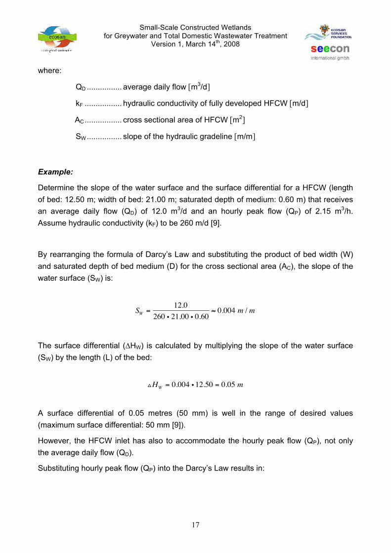
where:
QD ................ average daily flow [m3/d]
kF ................. hydraulic conductivity of fully developed HFCW [m/d]
AC ................. cross sectional area of HFCW [m2]
SW ................ slope of the hydraulic gradeline [m/m]
Example:
Determine the slope of the water surface and the surface differential for a HFCW (length of bed: 12.50 m; width of bed: 21.00 m; saturated depth of medium: 0.60 m) that receives an average daily flow (QD) of 12.0 m3/d and an hourly peak flow (QP) of 2.15 m3/h. Assume hydraulic conductivity (kF) to be 260 m/d [9].
By rearranging the formula of Darcy’s Law and substituting the product of bed width (W) and saturated depth of bed medium (D) for the cross sectional area (AC), the slope of the water surface (SW) is:
The surface differential ("HW) is calculated by multiplying the slope of the water surface (SW) by the length (L) of the bed:
A surface differential of 0.05 metres (50 mm) is well in the range of desired values (maximum surface differential: 50 mm [9]).
However, the HFCW inlet has also to accommodate the hourly peak flow (QP), not only the average daily flow (QD).
Substituting hourly peak flow (QP) into the Darcy’s Law results in:
SW =
12.0260 i 21.00 i 0.60
! 0.004 m / m!
!HW = 0.004 i 12.50 = 0.05 m !
Small-Scale Constructed Wetlands for Greywater and Total Domestic Wastewater Treatment
Version 1, March 14th, 2008
18
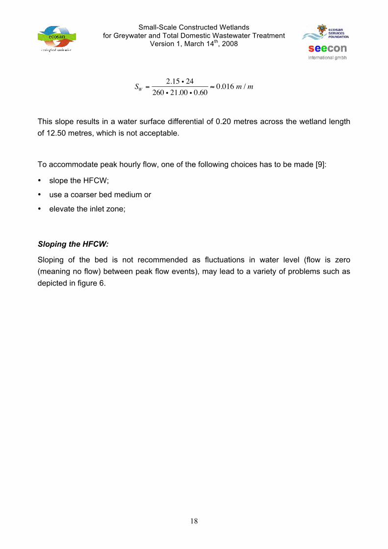
This slope results in a water surface differential of 0.20 metres across the wetland length of 12.50 metres, which is not acceptable.
To accommodate peak hourly flow, one of the following choices has to be made [9]:
• slope the HFCW;
• use a coarser bed medium or
• elevate the inlet zone;
Sloping the HFCW:
Sloping of the bed is not recommended as fluctuations in water level (flow is zero (meaning no flow) between peak flow events), may lead to a variety of problems such as depicted in figure 6.
SW =
2.15 i 24260 i 21.00 i 0.60
! 0.016 m / m!

Small-Scale Constructed Wetlands for Greywater and Total Domestic Wastewater Treatment
Version 1, March 14th, 2008
19
Coarser bed media:
Using coarser bed media (25 – 50 mm) in the inlet regions of the wetland bed should result in a hydraulic conductivity greater than 260 m/d. The question of how much coarse medium to use requires knowledge of the biofilm penetration distance, which (based on the present understanding of HFCWs) cannot be determined quantitatively.
Elevated inlet distribution zone:
Construction of an inlet distribution zone above the water level in the main portion of the HFCW allows the system to have some surge volume to accommodate the high-flow events (figure 7).
(source: [9])
figure 6: Potential pitfalls for steeply sloped HFCW designs

Small-Scale Constructed Wetlands for Greywater and Total Domestic Wastewater Treatment
Version 1, March 14th, 2008
20
2.4 Construction details and other important information
• The location of the HFCW should be safe from flooding.
• If available, natural slope avoids the need for pumps.
• HFCW should be integrated into the landscape as much as possible and should have a pleasant appearance.
• Surface water must be diverted away from the HFCW.
• If the existing soil has a permeability coefficient of < 10-8 m/s, no artificial sealing layer is necessary for sewage treatment applications. In this case a density test (after Procter) has to be performed. Constructed wetland systems in soil with a higher permeability require sealing of the bottom and sides so that untreated or partly treated wastewater cannot infiltrate to the groundwater. This can be achieved by [11]:
! concrete or plastic tank
! Plastic liner, thickness ! 1 mm, root resistant, preferably from polyethylene or equivalent material. The liner has to be protected against damages caused by rocks of the existing soil and by sharp edged gravel of the drainage layer. Geotextiles may be used for prevention of such damages. The liner should be UV resistant, if exposed to the sun
! Clay sealing with a verified thickness of ! 30 cm. The clay sealing has to be compacted properly.
! Mixture of existing soil with bentonite or very fine clay (two layers of 20 cm each, mixed and compacted separately).
(source: [9])
figure 7: HFCW with elevated inlet distribution zone

Small-Scale Constructed Wetlands for Greywater and Total Domestic Wastewater Treatment
Version 1, March 14th, 2008
21
After finishing the sealing a leakage test should be carried out by filling the bed with water. If the loss is less than 2 mm overnight, the sealing is satisfactory.
For large-scale projects and/or for repetitive use of the same media on a larger number of small-scale projects, field or laboratory testing for hydraulic conductivity (k) and porosity (VVS) is recommended.
• Washed river gravel is the preferred filter media. For the main filter body, fine to medium gravel sizes (Ø 5 to 10 mm) should be used. Stones or coarse gravel (Ø 50 to 100 mm) are the preffered material for the inlet and outlet zones, which should be build as 0.5 m wide distribution and collection trenches around and over the influent and effluent manifolds. The main filter body is separated from the inlet and outlet zones by 15 cm wide intermediate layers of medium gravel sizes (Ø 20 mm).
• PVC pipes (Ø 100 mm) with 25 mm drilled holes are acceptable for inlet and outlet manifolds.
• Inlet structures must distribute the incoming wastewater uniformly across the infiltration cross-section, without leading to clogging of the filter media.
• The outlet manifold should connect to either a swivelling standpipe or a flexible hose in a manhole to permit water level control in the HFCW.
• The construction of in- and outflow devices must allow for cleaning with mechanical or high pressure flushing tools.
• A freeboard of at least 20 cm (distance from bed surface to the upper edge of the lateral sealing) is to be provided.
• Local plant species should be used on the bed. The preferred species include: cattail, sedge, rush, soft stem bulrush, and reeds. Decorative, flowering plants can be used especially around the edges of the bed.
• The HFCW should be protected from unauthorized access, but be accessible for maintenance. There should be free access to all operational points, like manholes, pumping stations, maintenance locations and sampling points. The access has to be constructed in a way, that crossing of the HFCW is avoided.

Small-Scale Constructed Wetlands for Greywater and Total Domestic Wastewater Treatment
Version 1, March 14th, 2008
22
3 SAMPLE DESIGN PROBLEM “VERTICAL FLOW CONSTRUCTED WETLAND”
The following sample design problem provides a simplified design approach for a vertical flow constructed wetland. Designing is based on hydraulic and organic design criteria only and does not take into consideration other design parameters such as nutrient removal, pathogen reduction, etc.
Please note that design parameters (e.g. specific wastewater production, BOD load of raw wastewater, etc.) have been chosen solely to exemplify designing of a small-scale constructed wetland system presented as sample design problems in this training material and must not be applied for designing of real-life wastewater management systems without verification. For proper designing of real-life projects design parameters have to be set in all conscience.
3.1 Determination of average daily wastewater production, mean hourly flow, peaking factor and peak hourly flow
Analogue to chapter 2.1.
3.2 Pretreatment of greywater and/or total domestic wastewater
Analogue to chapter 2.2.
3.3 Sizing of siphon tank or pump sump
Pre-treated water is pulse-loaded onto the surface of the VFCW. Intermittent feeding happens usually in 3 to 4 batches per day.
Example:
Determine the volume of a single batch to be pulse-loaded onto the surface of the wetland when 4 batches shall be applied per day. Average daily flow is 12.0 m3/d.
The volume of each batch (QB) is calculated to be:

Small-Scale Constructed Wetlands for Greywater and Total Domestic Wastewater Treatment
Version 1, March 14th, 2008
23
3.4 Sizing of Vertical Flow Constructed Wetland
The surface area of the VFCW is determined by comparing the impact of hydraulic and organic loading criteria, and adopting the larger of the two surface areas.
Maximum organic surface load (OSL) for VFCWs are given as follows:
• organic surface load: 20 to 40 [11] and up to 60g [2] BOD5/m#/day
Common hydraulic surface loads (HSL) for HFCWs are given as follows:
• hydraulic surface load: 50 to 130 [11] and up to 200 l/m#/day
Example:
Residents of a housing society want to reuse treated wastewater for irrigation of lawns and gardens. Due to space constraints going for a HFCW is not possible (required surface area: 260 m2; please see chapter 2.3.1 for your reference). Average daily flow (QD) is ca. 12,000 litres per day (12.0 m3/d) and biogas settler effluent concentration is 256 mg BOD/l. Design organic surface loading (OSL) is 40 g BOD/m2/d and hydraulic surface loading is 200 l/m#/day.
Required surface area for the VFCW with respect to hydraulic loading criteria (AHYD) is calculated by dividing average daily flow (12,000 l/d) by the design hydraulic surface load (200 l/m#/d):
QB =12.04
= 3.0 m3 / batch!
AHYD =12,000200
= 60 m2
!

Small-Scale Constructed Wetlands for Greywater and Total Domestic Wastewater Treatment
Version 1, March 14th, 2008
24
Required surface area for the VFCW with respect to organic loading criteria (ABOD) is calculated by dividing average daily BOD load by the design organic surface load (40 g BOD/m2/d):
The larger of the two surface areas governs the design of the VFCW:
3.5 Construction details and other important information
• The location of the VFCW should be safe from flooding.
• If available, natural slope avoids the need for pumps.
• VFCW should be integrated into the landscape as much as possible and should have a pleasant appearance.
• Surface water must be diverted away from the HFCW.
• If the existing soil has a permeability coefficient of < 10-8 m/s, no artificial sealing layer is necessary for sewage treatment applications. In this case a density test (after Procter) has to be performed. Constructed wetland systems in soil with a higher permeability require sealing of the bottom and sides so that untreated or partly treated wastewater cannot infiltrate to the groundwater. This can be achieved by [11]:
! concrete or plastic tank
! Plastic liner, thickness ! 1 mm, root resistant, preferably from polyethylene or equivalent material. The liner has to be protected against damages caused by rocks of the existing soil and by sharp edged gravel of the drainage layer. Geotextiles may be used for prevention of such damages. The liner should be UV resistant, if exposed to the sun
! Clay sealing with a verified thickness of ! 30 cm. The clay sealing has to be compacted properly.
! Mixture of existing soil with bentonite or very fine clay (two layers of 20 cm each, mixed and compacted separately).
ABOD =
256 i 12,00040 i 1,000
! 77 m2
!
A = MAX 60;77[ ] ! 80 m2!

Small-Scale Constructed Wetlands for Greywater and Total Domestic Wastewater Treatment
Version 1, March 14th, 2008
25
After finishing the sealing a leakage test should be carried out by filling the bed with water. If the loss is less than 2 mm overnight, the sealing is to be considered as satisfactory.
• Washed river sand and gravel are the preferred filter media;
! top layer: 10 cm fine gravel (Ø 8/16 mm),
! main layer: 60 to 80 cm coarse sand (Ø 1/4 mm),
! intermediate layer: 10 cm fine gravel (Ø 4/8 mm),
! drainage layer: 20 cm coarse gravel (Ø 16/32 mm).
• A freeboard of at least 25 cm (distance from bed surface to the upper edge of the lateral sealing) is to be provided.
• PVC pipes (Ø 50 to 75 mm) with drilled holes are acceptable for inlet and outlet manifolds. The distribution system has to be designed and constructed in such a way that they distribute the incoming wastewater uniformly over the surface of the VFCW without leading to the formation of erosion furrows on the bed surface. After each application the pipes of the inflow construction should run empty. This prevents bacterial growth and resulting clogging problems.
• PVC pipes (Ø 100 mm) with drilled holes are acceptable for outlet manifolds.
• The construction of in- and outflow devices must allow for cleaning with mechanical or high pressure flushing tools.
• Local plant species should be used on the bed. The preferred species include: cattail, sedge, rush, soft stem bulrush, and reeds. Decorative, flowering plants can be used around the edges of the bed.
• The VFCW should be protected from unauthorized access, but be accessible for maintenance. There should be free access to all operational points, like manholes, pumping stations, maintenance locations and sampling points. The access has to be constructed in a way, that crossing of the VFCW is avoided.
4 OPERATION AND MANAGEMENT
4.1 Selection of suitable plants
With the available experience the following list of species can be given [11]:
• Phragmites australis (reed)
• Phragmites karka (reed)

Small-Scale Constructed Wetlands for Greywater and Total Domestic Wastewater Treatment
Version 1, March 14th, 2008
26
• Arundo donax (Mediterranean reed)
• Typha latifolia (cattail)
• Typha angustifolia (cattail)
• Juncus (bulrush)
• Iris pseudacorus
• Schoenoplectus lacustris (bulrush)
For HFCW in principle all helophytes can be used, which are deep-rooted and oxygenate the rhizosphere through the roots. For vertical systems the plant selection is less critical, because the oxygen input is enhanced by the intermittent surface application [11].
4.2 Planting techniques
Planting of reeds can be done in the following way [11].
• Reeds can be planted as rhizomes, seedlings or planted clumps.
• Clumps can be planted during all seasons (2 piece/m2).
• Rhizomes grow best when planted in Pre-Monsoon (4 - 6 piece /m2).
• Seedlings should be planted in Pre-Monsoon (3 - 5 piece /m2).
Planting should be done from supporting boards to avoid compaction of the filter media. Initially the plants should be kept well watered, but not flooded. With well-developed shoots, the growth of weeds can be suppressed by periodical flooding. During the first growth period a sufficient supply of nutrients is required. If wastewater is used for initial watering precautions like avoidance of stagnation have to be taken to inhibit the formation of H2S within the filter bed [11].

Small-Scale Constructed Wetlands for Greywater and Total Domestic Wastewater Treatment
Version 1, March 14th, 2008
27
5 BIBLIOGRAPHY
[1] Wikipedia – The Free Encyclopedia (2006). http://en.wikipedia.org/wiki/Greywater (last accessed on February 13th, 2007)
[2] Morel A., Diener S. (2006). Greywater Management in Low and Middle-Income Countries, Review of different treatment systems for households or neighbourhoods. Swiss Federal Institute of Aquatic Science and Technology (Eawag). Dübendorf, Switzerland.
[3] NEERI (2006). Wise Water Management – Greywater Reuse in Rural Schools Guidance Manual from India
[4] CPHEEO (1999). Manual on Water Supply and Treatment (downloadable from: http://cpheeo.nic.in/) (last accessed on February 15th, 2007)
[5] Kerala Water Authority (2007). http://keralawater.org/home.htm (last accessed on February 15th, 2007)
[6] Arceivala, S.J., Asolekar, S.R. (2007). Wastewater Treatment for Pollution Control and Reuse (Third Edition). Tata McGraw-Hill Publishing Company Limited, ISBN 0-07-062099-7
[7] Mara, D. (2003). Domestic wastewater treatment in developing countries, 1. Earthscan, London
[8] OasisDesign (2006). http://www.oasisdesign.net/greywater/brancheddrain/index.htm#rightsystem (last accessed on March 3rd, 2006)
[9] Wallace, S.D., Knight, R.L. (2006). Small-scale constructed wetland treatment systems – feasibility, design criteria and O&M requirements, ISBN 1843397285, IWA Publishing, Alliance House, 12 caxton Street, London, United Kingdom
[10] NSF International (2000). Residential Wastewater Treatment Systems, NSF/ANSI 4-2000, NSF International: Ann Arbor, Michigan, United States
[11] Biswas, D. (2001). Guidelines on Construction, Operation and Application of Rootzone Treatment Systems for the Treatment of Municipal and Industrial Wastewater

Small-Scale Constructed Wetlands for Greywater and Total Domestic Wastewater Treatment
Version 1, March 14th, 2008
28
6 SKETCHES, TECHNICAL DRAWINGS

Small-Scale Constructed Wetlands for Greywater and Total Domestic Wastewater Treatment
Version 1, March 14th, 2008
29
figure 8: Conceptual sketch of HFCW

Small-Scale Constructed Wetlands for Greywater and Total Domestic Wastewater Treatment
Version 1, March 14th, 2008
30
figure 9: Detail inlet section HFCW
Small-Scale Constructed Wetlands for Greywater and Total Domestic Wastewater Treatment
Version 1, March 14th, 2008
31
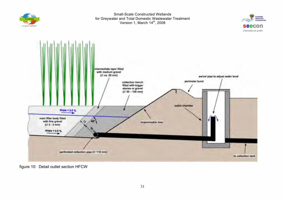
figure 10: Detail outlet section HFCW

Small-Scale Constructed Wetlands for Greywater and Total Domestic Wastewater Treatment
Version 1, March 14th, 2008
32
figure 11: Conceptual sketch VFCW (longitudinal section)

Small-Scale Constructed Wetlands for Greywater and Total Domestic Wastewater Treatment
Version 1, March 14th, 2008
33
figure 12: Conceptual sketch VFCW (cross section)

Small-Scale Constructed Wetlands for Greywater and Total Domestic Wastewater Treatment
Version 1, March 14th, 2008
http://www.ecosanservices.org
Ecosan Services Foundation (ESF) "Vishwa Chandra" 1002/42 Rajendra Nagar Pune – 411030, Maharashtra, India Phone/Fax: +91-(0)20-64000736 Email: [email protected] Web: http://www.ecosanservices.org
seecon gmbh Bahnhofstrasse 2 6110 Wolhusen, Switzerland Phone: +41-79-3666850 Email: [email protected] Web: http://www.seecon.ch