sludge handling post-earthquake – the christchurch
TRANSCRIPT
SLUDGE HANDLING POST-EARTHQUAKE – THE CHRISTCHURCH WASTEWATER TREATMENT PLANT STORY
Reuben Bouman 1, Dan Crocker
1, Lee Liaw
2, and Graeme Wells
1
1. CH2M Beca Ltd, 2. Christchurch City Council
ABSTRACT
The Christchurch Wastewater Treatment Plant (CWTP) operates six anaerobic digesters: two thermophilic
(55°C); followed by four mesophilic (37°C), processing a mixture of primary and secondary sludge. Sludge
digestion is a critical process at the treatment plant, producing significant amounts of methane, which is used to
generate on-site power, and reducing the quantity of solids for further processing and disposal.
During the Canterbury earthquake sequence, the digesters were damaged to varying degrees and in a variety of
ways. Fortunately, they were able to keep operating. The four mesophilic digesters have since been taken out of
service one at a time, for clean-out and repair. In doing so, it was discovered that they were 80 to 95% filled with
sand, yet they had continued to produce biogas. Also, although all four digesters are the same size and type, they
have some design differences, reflecting staged installation over a number of decades that have affected their
response to the earthquakes. The rapid sequence of work has provided a unique opportunity to identify these
commonalities and differences in damage and repair requirements.
This paper will describe:
Why and how the solids train as a whole continued to operate and potential consequence of a failure
The different types of damage to the digesters and the repair methods employed
The impact of the influx of sand
Lessons learned
KEY WORDS
Sludge, Biosolids, Earthquake, Digesters.
1. INTRODUCTION
The Christchurch Wastewater Treatment Plant (CWTP) operates six digesters in an arrangement known as
Temperature Phased Anaerobic Digestion (TPAD): two thermophilic (55°C); followed by four mesophilic
(37°C) digesters, processing a mixture of primary and secondary sludge. The digested sludge is then dewatered
in one of two belt presses and dried in one of two indirect thermal belt driers. Refer to Figure 1 for typical
operational details. Sludge digestion is a critical process at the treatment plant, producing significant amounts of
methane, which is used to generate on-site power, and reducing the quantity of solids for further processing and
disposal.
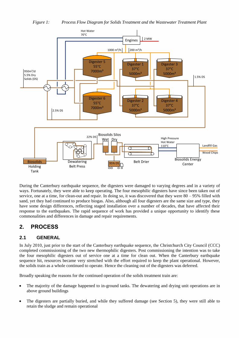
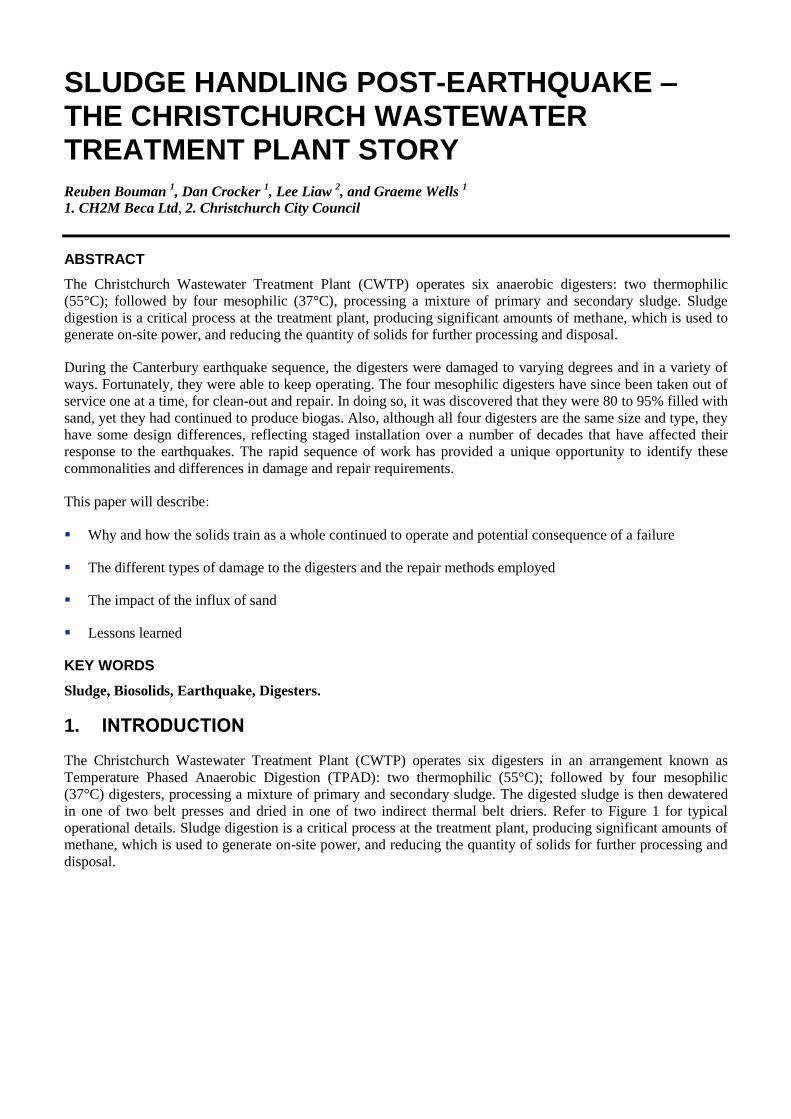
Figure 1: Process Flow Diagram for Solids Treatment and the Wastewater Treatment Plant
Digester 555°C
7000m³
Digester 137°C
5000m³
Digester 337°C
5000m³
Digester 437°C
5000m³
Digester 237°C
5000m³
Digester 655°C
7000m³
950m³/d5.5% Dry Solids (DS)
Engines
2.5% DS
1.5% DS
200 m³/h1000 m³/h
2 MW
Biosolids Holding
Tank
Dewatering Belt Press
Biosolids SilosWet Dry
22% DS
Belt DrierBiosolids Energy
Center
Hot Water70°C
High Pressure Hot Water110°C Landfill Gas
Wood Chips
95% DS
During the Canterbury earthquake sequence, the digesters were damaged to varying degrees and in a variety of
ways. Fortunately, they were able to keep operating. The four mesophilic digesters have since been taken out of
service, one at a time, for clean-out and repair. In doing so, it was discovered that they were 80 – 95% filled with
sand, yet they had continued to produce biogas. Also, although all four digesters are the same size and type, they
have some design differences, reflecting staged installation over a number of decades, that have affected their
response to the earthquakes. The rapid sequence of work has provided a unique opportunity to identify these
commonalities and differences in damage and repair requirements.
2. PROCESS
2.1 GENERAL
In July 2010, just prior to the start of the Canterbury earthquake sequence, the Christchurch City Council (CCC)
completed commissioning of the two new thermophilic digesters. Post commissioning the intention was to take
the four mesophilic digesters out of service one at a time for clean out. When the Canterbury earthquake
sequence hit, resources became very stretched with the effort required to keep the plant operational. However,
the solids train as a whole continued to operate. Hence the cleaning out of the digesters was deferred.
Broadly speaking the reasons for the continued operation of the solids treatment train are:
The majority of the damage happened to in-ground tanks. The dewatering and drying unit operations are in
above ground buildings
The digesters are partially buried, and while they suffered damage (see Section 5), they were still able to
retain the sludge and remain operational
All unit processes have N-1 capacity. i.e. one stand-by unit
Recent commissioning in Digesters 5 and 6, with good mixing (see Archer et al, 2008), meant that they were
able to pass on the increased grit load resulting from the earthquakes without excessive amounts of
liquefaction blocking the lower intake valves.
Having a two stage digestion process meant the even if one stage under-performed, the system as a whole
could cope
Digester temperature was maintained with a diesel boiler while gas production was interrupted/reduced
Because Digesters 1 to 4 are variable volume, this meant that even when the Biosolids Holding Tank was
lost due to earthquake damage, it was still practical to feed the dewatering plant directly from the digesters
The thermal drier can run on two fuel sources: Landfill gas and wood chips. Thus when the landfill gas
became temporarily unavailable the drier could continue to operate on wood chips
3. DIGESTERS
3.1 PERFORMANCE
The performance of the digesters over the earthquake sequence is given in Figures 2 to 6. Key points to note are:
Digesters 5 and 6 finished their biological commissioning in mid-July 2010 (see Bouman and Feary, 2011)
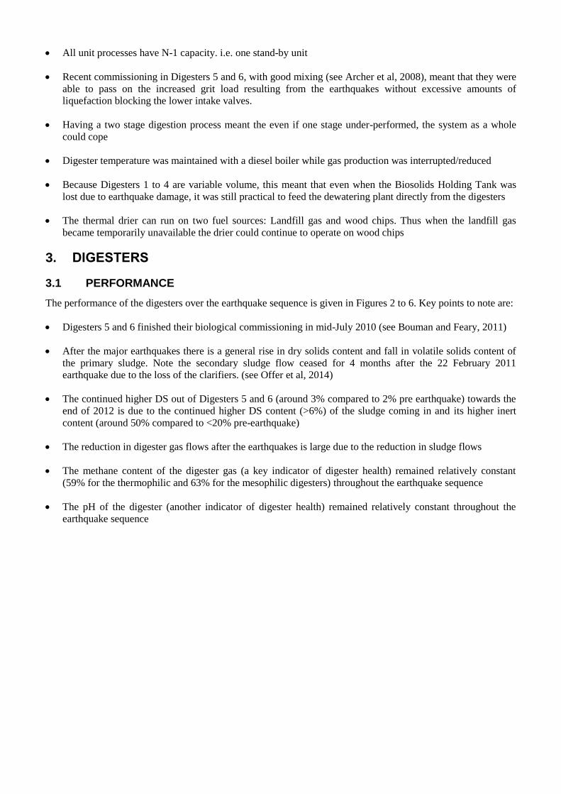
After the major earthquakes there is a general rise in dry solids content and fall in volatile solids content of
the primary sludge. Note the secondary sludge flow ceased for 4 months after the 22 February 2011
earthquake due to the loss of the clarifiers. (see Offer et al, 2014)
The continued higher DS out of Digesters 5 and 6 (around 3% compared to 2% pre earthquake) towards the
end of 2012 is due to the continued higher DS content (>6%) of the sludge coming in and its higher inert
content (around 50% compared to <20% pre-earthquake)
The reduction in digester gas flows after the earthquakes is large due to the reduction in sludge flows
The methane content of the digester gas (a key indicator of digester health) remained relatively constant
(59% for the thermophilic and 63% for the mesophilic digesters) throughout the earthquake sequence
The pH of the digester (another indicator of digester health) remained relatively constant throughout the
earthquake sequence
Figure 2: CWTP primary and secondary sludge dry solids data during the earthquake sequence
Figure 3: CWTP primary and secondary sludge volatile solids data during the earthquake sequence
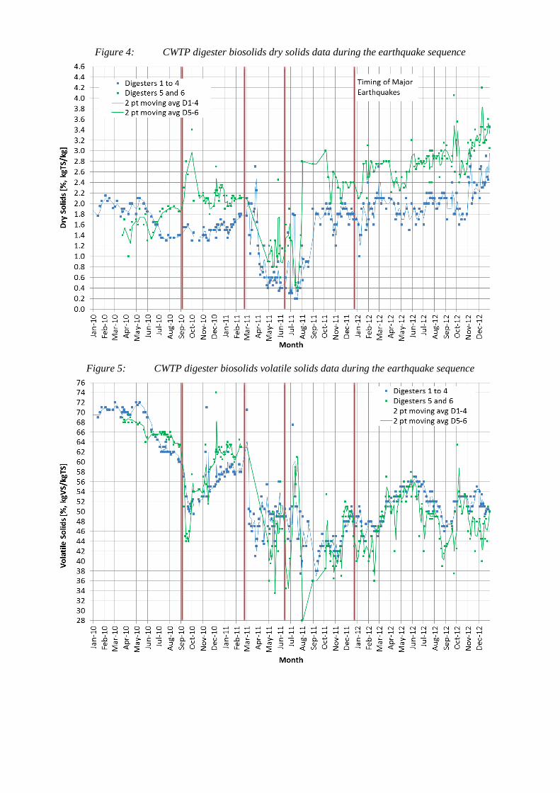
Figure 4: CWTP digester biosolids dry solids data during the earthquake sequence
Figure 5: CWTP digester biosolids volatile solids data during the earthquake sequence
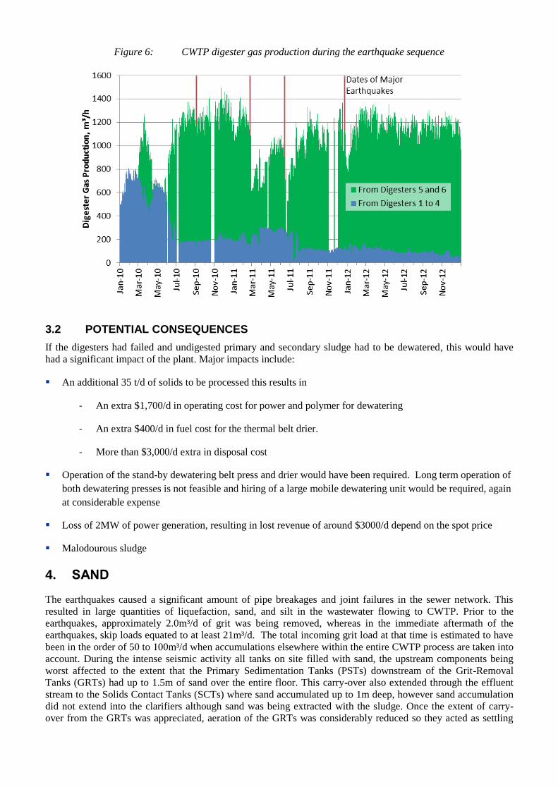
Figure 6: CWTP digester gas production during the earthquake sequence
3.2 POTENTIAL CONSEQUENCES
If the digesters had failed and undigested primary and secondary sludge had to be dewatered, this would have
had a significant impact of the plant. Major impacts include:
An additional 35 t/d of solids to be processed this results in
- An extra $1,700/d in operating cost for power and polymer for dewatering
- An extra $400/d in fuel cost for the thermal belt drier.
- More than $3,000/d extra in disposal cost
Operation of the stand-by dewatering belt press and drier would have been required. Long term operation of
both dewatering presses is not feasible and hiring of a large mobile dewatering unit would be required, again
at considerable expense
Loss of 2MW of power generation, resulting in lost revenue of around $3000/d depend on the spot price
Malodourous sludge
4. SAND
The earthquakes caused a significant amount of pipe breakages and joint failures in the sewer network. This
resulted in large quantities of liquefaction, sand, and silt in the wastewater flowing to CWTP. Prior to the
earthquakes, approximately 2.0m³/d of grit was being removed, whereas in the immediate aftermath of the
earthquakes, skip loads equated to at least 21m³/d. The total incoming grit load at that time is estimated to have
been in the order of 50 to 100m³/d when accumulations elsewhere within the entire CWTP process are taken into
account. During the intense seismic activity all tanks on site filled with sand, the upstream components being
worst affected to the extent that the Primary Sedimentation Tanks (PSTs) downstream of the Grit-Removal
Tanks (GRTs) had up to 1.5m of sand over the entire floor. This carry-over also extended through the effluent
stream to the Solids Contact Tanks (SCTs) where sand accumulated up to 1m deep, however sand accumulation
did not extend into the clarifiers although sand was being extracted with the sludge. Once the extent of carry-
over from the GRTs was appreciated, aeration of the GRTs was considerably reduced so they acted as settling
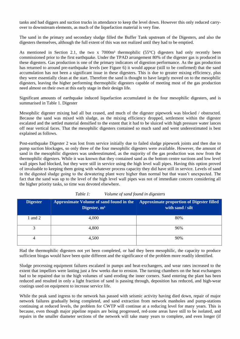
tanks and had diggers and suction trucks in attendance to keep the level down. However this only reduced carry-
over to downstream elements, as much of the liquefaction material is very fine.
The sand in the primary and secondary sludge filled the Buffer Tank upstream of the Digesters, and also the
digesters themselves, although the full extent of this was not realized until they had to be emptied.
As mentioned in Section 2.1, the two x 7000m³ thermophilic (55°C) digesters had only recently been
commissioned prior to the first earthquake. Under the TPAD arrangement 80% of the digester gas is produced in
these digesters. Gas production is one of the primary indicators of digestion performance. As the gas production
has returned to around pre-earthquake levels (see Figure 6) it would appear (still to be confirmed) that the sand
accumulation has not been a significant issue in these digesters. This is due to greater mixing efficiency, plus
they were essentially clean at the start. Therefore the sand is thought to have largely moved on to the mesophilic
digesters, leaving the higher performing thermophilic digesters capable of meeting most of the gas production
need almost on their own at this early stage in their design life.
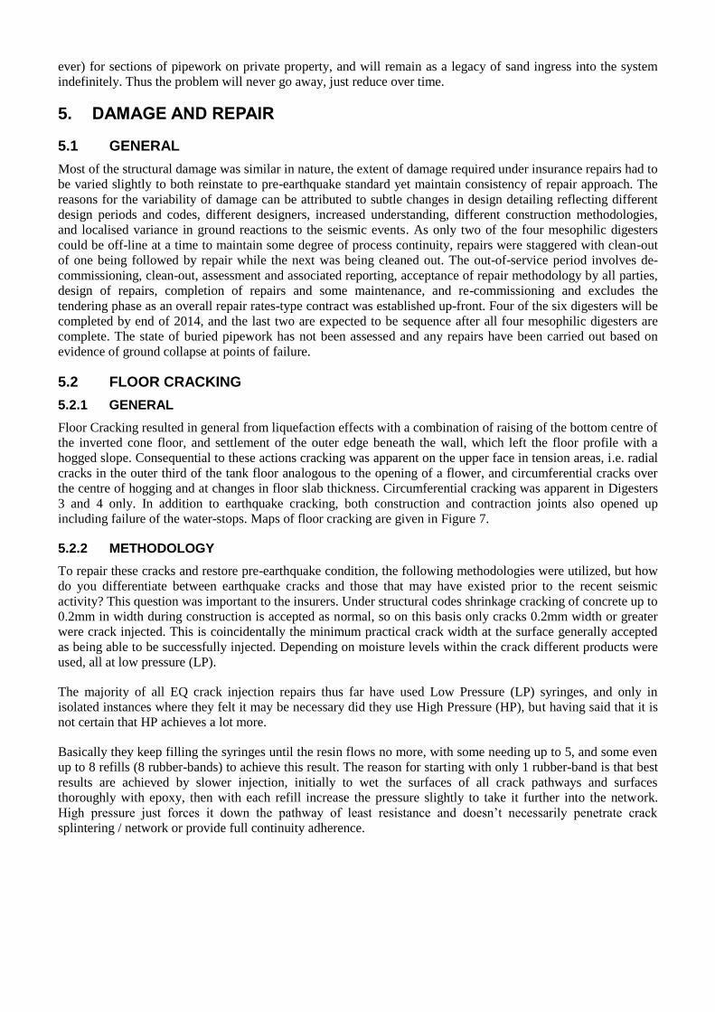
Significant amounts of earthquake induced liquefaction accumulated in the four mesophilic digesters, and is
summarised in Table 1. Digester
Mesophilic digester mixing had all but ceased, and much of the digester pipework was blocked / obstructed.
Because the sand was mixed with sludge, as the mixing efficiency dropped, settlement within the digester
escalated and the settled material densified to the extent that it had to be sluiced with high pressure water lances
off near vertical faces. That the mesophilic digesters contained so much sand and went underestimated is best
explained as follows.
Post-earthquake Digester 2 was lost from service initially due to failed sludge pipework joints and then due to
pump suction blockages, so only three of the four mesophilic digesters were available. However, the amount of
sand in the mesophilic digesters was underestimated, as the majority of the gas production was now from the
thermophilic digesters. While it was known that they contained sand as the bottom centre suctions and low level
wall pipes had blocked, but they were still in service using the high level wall pipes. Having this option proved
of invaluable to keeping them going with whatever process capacity they did have still in service. Levels of sand
in the digested sludge going to the dewatering plant were higher than normal but that wasn’t unexpected. The
fact that the sand was up to the level of the high level wall pipes was not of immediate concern considering all
the higher priority tasks, so time was devoted elsewhere.
Table 1: Volume of sand found in digesters
Digester Approximate Volume of sand found in the
Digester, m³
Approximate proportion of Digester filled
with sand / silt
1 and 2 4,000 80%
3 4,800 96%
4 4,500 90%
Had the thermophilic digesters not yet been completed, or had they been mesophilic, the capacity to produce
sufficient biogas would have been quite different and the significance of the problem more readily identified.
Sludge processing equipment failures escalated in pumps and heat-exchangers, and wear rates increased to the
extent that impellors were lasting just a few weeks due to erosion. The turning chambers on the heat exchangers
had to be repaired due to the high volumes of sand eroding the inner corners. Sand entering the plant has been
reduced and resulted in only a light fraction of sand is passing through, deposition has reduced, and high-wear
coatings used on equipment to increase service life.
While the peak sand ingress to the network has passed with seismic activity having died down, repair of major
network failures gradually being completed, and sand extraction from network manholes and pump-stations
continuing at reduced levels, the problem for CWTP will continue at a reducing level for many years. This is
because, even though major pipeline repairs are being progressed, red-zone areas have still to be isolated, and
repairs in the smaller diameter sections of the network will take many years to complete, and even longer (if
ever) for sections of pipework on private property, and will remain as a legacy of sand ingress into the system
indefinitely. Thus the problem will never go away, just reduce over time.
5. DAMAGE AND REPAIR
5.1 GENERAL
Most of the structural damage was similar in nature, the extent of damage required under insurance repairs had to
be varied slightly to both reinstate to pre-earthquake standard yet maintain consistency of repair approach. The
reasons for the variability of damage can be attributed to subtle changes in design detailing reflecting different
design periods and codes, different designers, increased understanding, different construction methodologies,
and localised variance in ground reactions to the seismic events. As only two of the four mesophilic digesters
could be off-line at a time to maintain some degree of process continuity, repairs were staggered with clean-out
of one being followed by repair while the next was being cleaned out. The out-of-service period involves de-
commissioning, clean-out, assessment and associated reporting, acceptance of repair methodology by all parties,
design of repairs, completion of repairs and some maintenance, and re-commissioning and excludes the
tendering phase as an overall repair rates-type contract was established up-front. Four of the six digesters will be
completed by end of 2014, and the last two are expected to be sequence after all four mesophilic digesters are
complete. The state of buried pipework has not been assessed and any repairs have been carried out based on
evidence of ground collapse at points of failure.
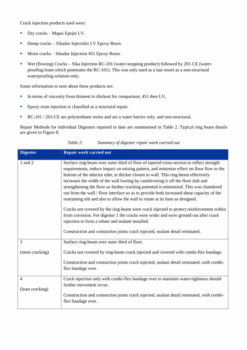
5.2 FLOOR CRACKING
5.2.1 GENERAL
Floor Cracking resulted in general from liquefaction effects with a combination of raising of the bottom centre of
the inverted cone floor, and settlement of the outer edge beneath the wall, which left the floor profile with a
hogged slope. Consequential to these actions cracking was apparent on the upper face in tension areas, i.e. radial
cracks in the outer third of the tank floor analogous to the opening of a flower, and circumferential cracks over
the centre of hogging and at changes in floor slab thickness. Circumferential cracking was apparent in Digesters
3 and 4 only. In addition to earthquake cracking, both construction and contraction joints also opened up
including failure of the water-stops. Maps of floor cracking are given in Figure 7.
5.2.2 METHODOLOGY
To repair these cracks and restore pre-earthquake condition, the following methodologies were utilized, but how
do you differentiate between earthquake cracks and those that may have existed prior to the recent seismic
activity? This question was important to the insurers. Under structural codes shrinkage cracking of concrete up to
0.2mm in width during construction is accepted as normal, so on this basis only cracks 0.2mm width or greater
were crack injected. This is coincidentally the minimum practical crack width at the surface generally accepted
as being able to be successfully injected. Depending on moisture levels within the crack different products were
used, all at low pressure (LP).
The majority of all EQ crack injection repairs thus far have used Low Pressure (LP) syringes, and only in
isolated instances where they felt it may be necessary did they use High Pressure (HP), but having said that it is
not certain that HP achieves a lot more.
Basically they keep filling the syringes until the resin flows no more, with some needing up to 5, and some even
up to 8 refills (8 rubber-bands) to achieve this result. The reason for starting with only 1 rubber-band is that best
results are achieved by slower injection, initially to wet the surfaces of all crack pathways and surfaces
thoroughly with epoxy, then with each refill increase the pressure slightly to take it further into the network.
High pressure just forces it down the pathway of least resistance and doesn’t necessarily penetrate crack
splintering / network or provide full continuity adherence.
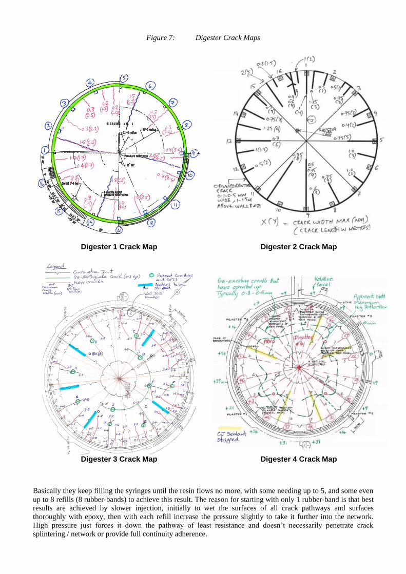
Figure 7: Digester Crack Maps
Digester 1 Crack Map
Digester 2 Crack Map
Digester 3 Crack Map
Digester 4 Crack Map
Basically they keep filling the syringes until the resin flows no more, with some needing up to 5, and some even
up to 8 refills (8 rubber-bands) to achieve this result. The reason for starting with only 1 rubber-band is that best
results are achieved by slower injection, initially to wet the surfaces of all crack pathways and surfaces
thoroughly with epoxy, then with each refill increase the pressure slightly to take it further into the network.
High pressure just forces it down the pathway of least resistance and doesn’t necessarily penetrate crack
splintering / network or provide full continuity adherence.
Crack injection products used were:
Dry cracks – Mapei Epojet LV.
Damp cracks – Sikadur Injectokit LV Epoxy Resin.
Moist cracks – Sikadur Injection 451 Epoxy Resin.
Wet (flowing) Cracks – Sika Injection RC-101 (water-stopping product) followed by 201-CE (water-
proofing foam which penetrates the RC-101). This was only used as a last resort as a non-structural
waterproofing solution only.
Some information to note about these products are:
In terms of viscosity from thinnest to thickest for comparison; 451 then LV,
Epoxy resin injection is classified as a structural repair.
RC-101 / 201-CE are polyurethane resins and are a water barrier only, and non-structural.
Repair Methods for individual Digesters repaired to date are summarised in Table 2. Typical ring beam details
are given in Figure 8.
Table 2: Summary of digester repair work carried out
Digester Repair work carried out
1 and 2 Surface ring-beam over outer third of floor of tapered cross-section to reflect strength
requirements, reduce impact on mixing pattern, and minimize effect on floor flow to the
bottom of the eductor tube, ie thicker closest to wall. This ring-beam effectively
increases the width of the wall footing by cantilevering it off the floor slab and
strengthening the floor so further cracking potential is minimized. This was chamfered
out from the wall / floor interface so as to provide both increased shear capacity of the
restraining nib and also to allow the wall to rotate at its base as designed.
Cracks not covered by the ring-beam were crack injected to protect reinforcement within
from corrosion. For digester 1 the cracks were wider and were ground out after crack
injection to form a rebate and sealant installed.
Construction and contraction joints crack injected, sealant detail reinstated.
3
(most cracking)
Surface ring-beam over outer third of floor.
Cracks not covered by ring-beam crack injected and covered with combi-flex bandage.
Construction and contraction joints crack injected, sealant detail reinstated, with combi-
flex bandage over.
4
(least cracking)
Crack injection only with combi-flex bandage over to maintain water-tightness should
further movement occur.
Construction and contraction joints crack injected, sealant detail reinstated, with combi-
flex bandage over.
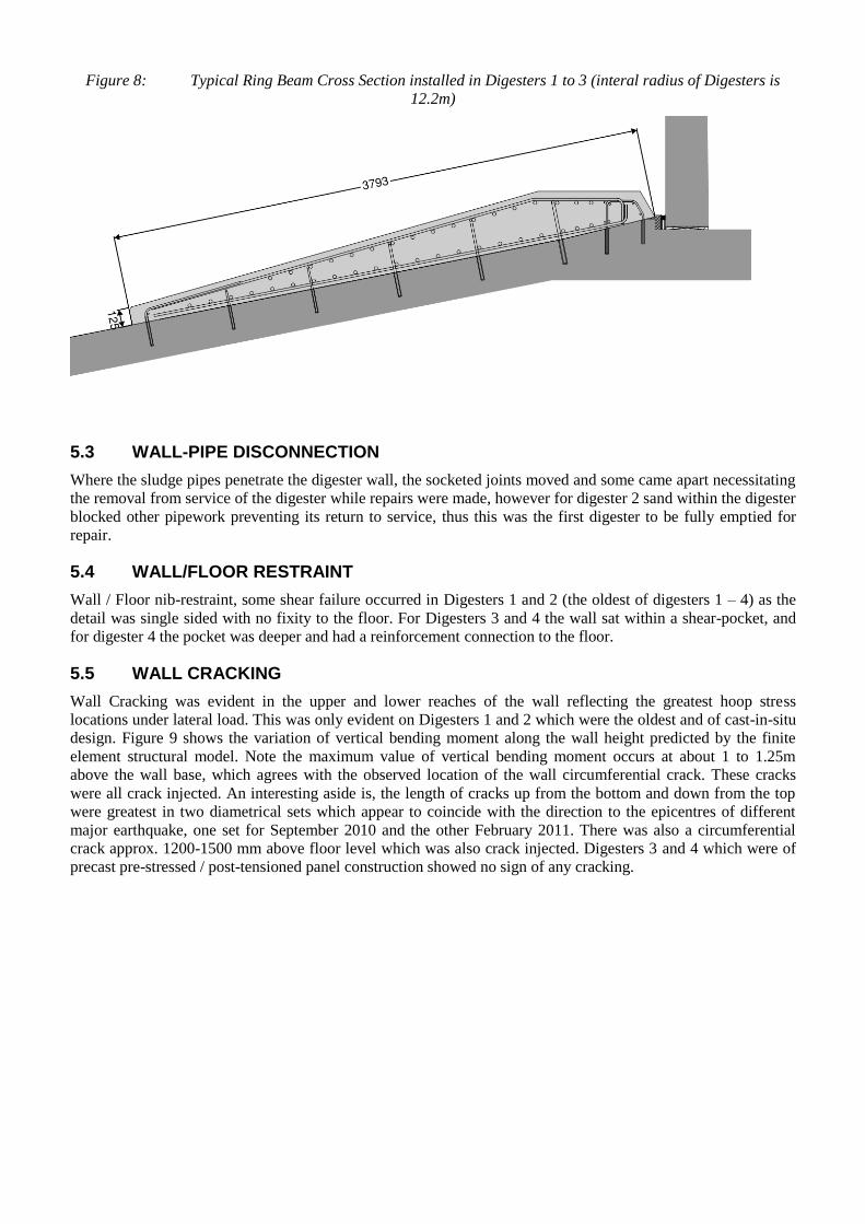
Figure 8: Typical Ring Beam Cross Section installed in Digesters 1 to 3 (interal radius of Digesters is
12.2m)
5.3 WALL-PIPE DISCONNECTION
Where the sludge pipes penetrate the digester wall, the socketed joints moved and some came apart necessitating
the removal from service of the digester while repairs were made, however for digester 2 sand within the digester
blocked other pipework preventing its return to service, thus this was the first digester to be fully emptied for
repair.
5.4 WALL/FLOOR RESTRAINT
Wall / Floor nib-restraint, some shear failure occurred in Digesters 1 and 2 (the oldest of digesters 1 – 4) as the
detail was single sided with no fixity to the floor. For Digesters 3 and 4 the wall sat within a shear-pocket, and
for digester 4 the pocket was deeper and had a reinforcement connection to the floor.
5.5 WALL CRACKING
Wall Cracking was evident in the upper and lower reaches of the wall reflecting the greatest hoop stress
locations under lateral load. This was only evident on Digesters 1 and 2 which were the oldest and of cast-in-situ
design. Figure 9 shows the variation of vertical bending moment along the wall height predicted by the finite
element structural model. Note the maximum value of vertical bending moment occurs at about 1 to 1.25m
above the wall base, which agrees with the observed location of the wall circumferential crack. These cracks
were all crack injected. An interesting aside is, the length of cracks up from the bottom and down from the top
were greatest in two diametrical sets which appear to coincide with the direction to the epicentres of different
major earthquake, one set for September 2010 and the other February 2011. There was also a circumferential
crack approx. 1200-1500 mm above floor level which was also crack injected. Digesters 3 and 4 which were of
precast pre-stressed / post-tensioned panel construction showed no sign of any cracking.
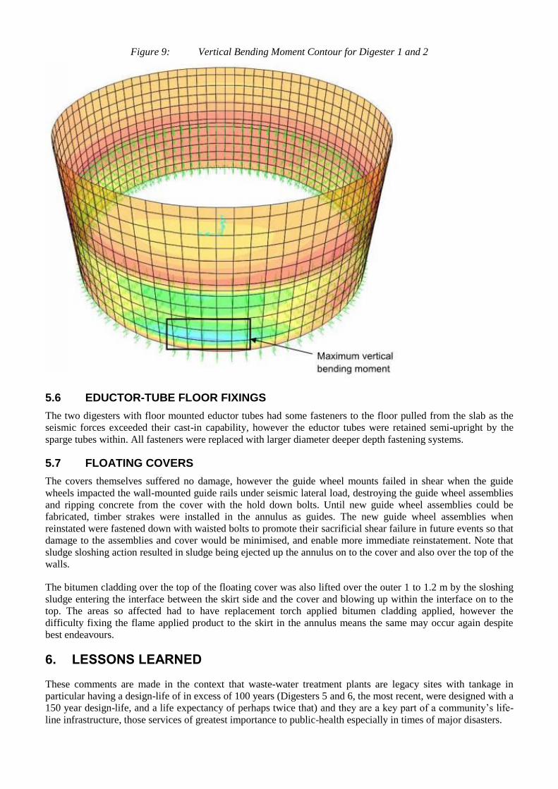
Figure 9: Vertical Bending Moment Contour for Digester 1 and 2
5.6 EDUCTOR-TUBE FLOOR FIXINGS
The two digesters with floor mounted eductor tubes had some fasteners to the floor pulled from the slab as the
seismic forces exceeded their cast-in capability, however the eductor tubes were retained semi-upright by the
sparge tubes within. All fasteners were replaced with larger diameter deeper depth fastening systems.
5.7 FLOATING COVERS
The covers themselves suffered no damage, however the guide wheel mounts failed in shear when the guide
wheels impacted the wall-mounted guide rails under seismic lateral load, destroying the guide wheel assemblies
and ripping concrete from the cover with the hold down bolts. Until new guide wheel assemblies could be
fabricated, timber strakes were installed in the annulus as guides. The new guide wheel assemblies when
reinstated were fastened down with waisted bolts to promote their sacrificial shear failure in future events so that
damage to the assemblies and cover would be minimised, and enable more immediate reinstatement. Note that
sludge sloshing action resulted in sludge being ejected up the annulus on to the cover and also over the top of the
walls.
The bitumen cladding over the top of the floating cover was also lifted over the outer 1 to 1.2 m by the sloshing
sludge entering the interface between the skirt side and the cover and blowing up within the interface on to the
top. The areas so affected had to have replacement torch applied bitumen cladding applied, however the
difficulty fixing the flame applied product to the skirt in the annulus means the same may occur again despite
best endeavours.
6. LESSONS LEARNED
These comments are made in the context that waste-water treatment plants are legacy sites with tankage in
particular having a design-life of in excess of 100 years (Digesters 5 and 6, the most recent, were designed with a
150 year design-life, and a life expectancy of perhaps twice that) and they are a key part of a community’s life-
line infrastructure, those services of greatest importance to public-health especially in times of major disasters.
Pipe Connections to Structures - The benefit of flexible pipelines and multiple movement joints immediately
adjacent to structures was highlighted, the more the better, and a minimum of three.
Concrete Tank Design - The benefit of robust / conservative design in major seismic events was
demonstrated by structures moving as a whole and not breaking apart. Structure Floors that utilized more
recent thin element philosophies and technologies did not fare so well.
Digester Sludge Extraction - This needs to be concentrated on suction from bottom centre most of the time
(80 – 90%) to ensure that settled material is kept moving through the process and does not get any
opportunity to densify or accumulate blocking suction entry. While back-flushing of the suction line will
clear minor blockages, once material starts to accumulate it rapidly escalates, it should not be relied upon in
isolation. Regular automated back-flushing of the bottom center suction is encouraged to reduce the
frequency of blockages.
Digester wall-pipes – The main purpose of these is to assist with tank mixing as part of sludge heating /
recirculation loop, they also proved invaluable for maintenance of some process capability once bottom
centre suction was lost, by sludge extraction first at low wall pipe level then once the digester continued to
fill with sand, from the high level wall-pipes.
Eductor Tube - Central eductor tube mixing system works very well on site under normal circumstances,
however there are several key–points that should be noted that became readily apparent in the aftermath.
- Eductor tubes should be floor mounted with clearance to the floor calculated to maintain good entry
velocity (1 m/s) and thus good transport of material settling to the point of suction removal. Those
that were top-hung have now been changed to floor mounted, as the greater clearance to the floor
when the floating cover rises results in a drop in velocity down the floor slope.
- The upper level of the eductor tube must be maximized within the constraints of the floating cover,
or sludge surface with fixed covers, to maximize the depth of penetration of the sparge-tubes. This is
especially so for floating covers as the cover mounted sparge-tubes have reducing penetration within
the confines of the eductor tube as the cover rises, and with reduced confined penetration comes
reduced lift and velocity in the eductor tube and so reduced mixing and greater deposition on the
floor. Even with these maximized CFD work on Digester 4 has shown that while at minimum cover
height the velocity in the eductor tube was approx. 1 m/s, at mid cover travel (approx. 1.05 m) it had
reduced to 0.87 m/s, and at maximum cover travel of 2.1 m it had reduced from 1 m/s to 0.39 m/s.
Those eductor tubes that were too short, or the sparge tubes not long enough, have now been
corrected.
Digester Mixing - This is a key element of digester operation, and indications are that Digesters 5 and 6 have
performed well given the emphasis placed on that at the time of their design. The eductor tube top and
bottom levels were optimized, spiral vanes incorporated both inside and outside of the eductor tube, a
deflector cone incorporated over the eductor tube, and the digester floor slope steepened slightly from (1 in 5
to 1 in 4). Through good mixing, keeping deposition material moving to the bottom centre for removal, and
keeping the finer sands in suspension, any sand is kept moving through the process with the sludge and
doesn’t accumulate within the digesters.
Intense areas of Corrosion - A non-earthquake related lesson learnt relates to some areas of floating cover
and eductor tube, discovered to have suffered intense corrosion despite good corrosion protective coatings of
the steel-work and otherwise good performance of those coatings. What has been established is that these
were areas where rag and fibre accumulates in corners, between members, on protrusions and the like.
Despite being anaerobic digesters (i.e. devoid of oxygen to support corrosion) within the core of the rag,
fibre, and sludge accumulation up against the coated steel, it has been concluded that a very intense local
micro-environment evolves, with the entrapped nutrients providing an optimum environment for bacterial
growth, generating greatly increased H2S levels within and intense acidic attack. This is more generally
described as microbial induced corrosion (MIC).
Thin Film Epoxy Coatings - Historically, these have protected wastewater facilities for many years.
Hydrogen sulphide (H2S) gas emissions were generally low and MIC was of minimal consequence.
Legislation began to be implemented approximately 30 years ago to get industry to reduce levels of toxic
heavy metals (such as chromium, nickel and lead) discharged into wastewater systems. As a result, microbial
activity began to increase and indeed thrive in wastewater systems because of the reduced toxicity. Much
higher levels of H2S are now commonly recorded and research reveals that various types of acid conversion
bacteria are able to convert this gas into sulphuric acid at up to 60% concentration. Older wastewater
facilities that have coped well in the past now suffer severe corrosion and some newer facilities are seeing
corrosion rates in excess of 1 mm/year. To combat this, more chemically resistant top-coats are required in
these areas.
Sludge Pumps and Heat Exchangers - The presence of increased sand levels in the sludge stream has
increased wear in mechanical items, such as sludge pumps and heat exchangers, especially those with small
clearances. What has been learnt is that while the drive for high performance and energy efficiency of recent
years should be considered, in the case of sludge this must be weighed against increased wear and
maintenance requirements. Where pumps of less efficiency with greater clearances were in use, these wear
effects were less. A realistic total life costing incorporating conservative maintenance requirements should
be considered.
Some heat exchangers rely on turbulence to improve heat transfer, however in these areas of turbulence with
sludge containing sand, the wear level increases, particularly between turning chamber and re-entry into
pipes, so increased material thickness in these areas should be considered.
7. REFERNCES
Archer, H., Bouman, R., Wells, G., and Bourke, M. (2008) Design of thermophilic digesters at the Christchurch
wastewater treatment plant Water NZ Conference Proceedings
Bouman, R.,. and Feary, J., (2011) Benefits of Thermophlic Digestion at Christchurch Wastewater Treatment
Plant, Water NZ Conference Proceedings
Offer, G., (2014) Billings, I. and Scott, T. (2014) Earthquake Repairs a Christchurch WWTP – Clarifying the
Situation Water NZ Conference Proceedings