sliding door hardware - b&d doors & openers door hardware slide-a-track straight light...
TRANSCRIPT
sliding door hardware
Slide-A-Track™
Straight Light Double Track Systems
Straight Medium Double Track Systems
Straight Heavy Double Track Systems
General information
Straight Light Single Track Systems
Straight Medium Single Track Systems
Straight Heavy Single Track Systems
General information
June 2016SECTION 12/1
Product Code
SAT
RETURN TO INDEX
Bangor Sliding Door Hardwareindustrial, commercial and rural range of straight track systems
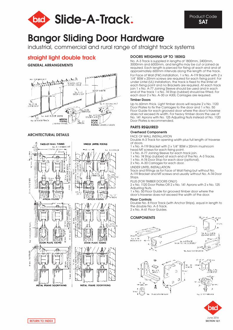
straight light double trackgENERAl ARRANgEmENTS
ARCHITECTURAl DETAIlS
DOORS WEIgHINg UP TO 180kgNo. A-3 Track is supplied in lengths of 1800mm, 2400mm, 3000mm and 6000mm, and lengths may be cut or joined as required. Each length is pierced for fixing at each end and at approximately 600mm intervals along the length of the track.For Face of Wall (FW) installation, 1 x No. A-119 Bracket with 2 x 1/4” BSW x 20mm screws are required for each fixing point. For under Lintel (UL) installation, the track is fixed to the lintel at each fixing point and no Brackets are required. At each track join 1 x No. A-77 Joining Sleeve should be used and in each end of the track 1 x No. 74 Stop (rubber) should be fitted. For each door 2 x No. A-30 or A30L Carriages are required.
Timber DoorsUp to 60mm thick. Light timber doors will require 2 x No. 1120 Door Plates to fix the Carriages to the door and 1 x No. 50 Floor Guide for each grooved door where the door’s traverse does not exceed its width. For heavy timber doors the use of No. 141 Aprons with No. 125 Adjusting Nuts instead of No. 1120 Door Plates is recommended.
PARTS REQUIREDOverhead ComponentsFACE oF WALL INSTALLATIoNDouble A-3 Track for opening width plus full length of traverse of doors.1 x No. A-119 Bracket with 2 x 1/4” BSW x 20mm mushroom head MT screws for each fixing point.1 x No. A-77 Joining Sleeve for each track join.1 x No. 74 Stop (rubber) at each end of the No. A-3 Tracks.1 x No. A-74 Door Stop for each door (optional).2 x No. A-30 Carriages for each door.UNDEr LINTEL INSTALLATIoNTrack and fittings as for Face of Wall Fixing but without No. A-119 Bracket and MT screws and usually without No. A-74 Door Stops.PLUS (For TIMBEr DoorS oNLy)2 x No. 1120 Door Plates or 2 x No. 141 Aprons with 2 x No. 125 Adjusting Nuts.1 x No. 50 Floor Guide for grooved timber door where the door’s traverse does not exceed the width of the door.
Floor ControlsDouble No. 8 Floor Track (with Anchor Strips), equal in length to the double No. A-3 Track.2 x No. A-61 Floor Guides.
COmPONENTS
June 2016SECTION 12/2
Product Code
SAT
RETURN TO INDEX
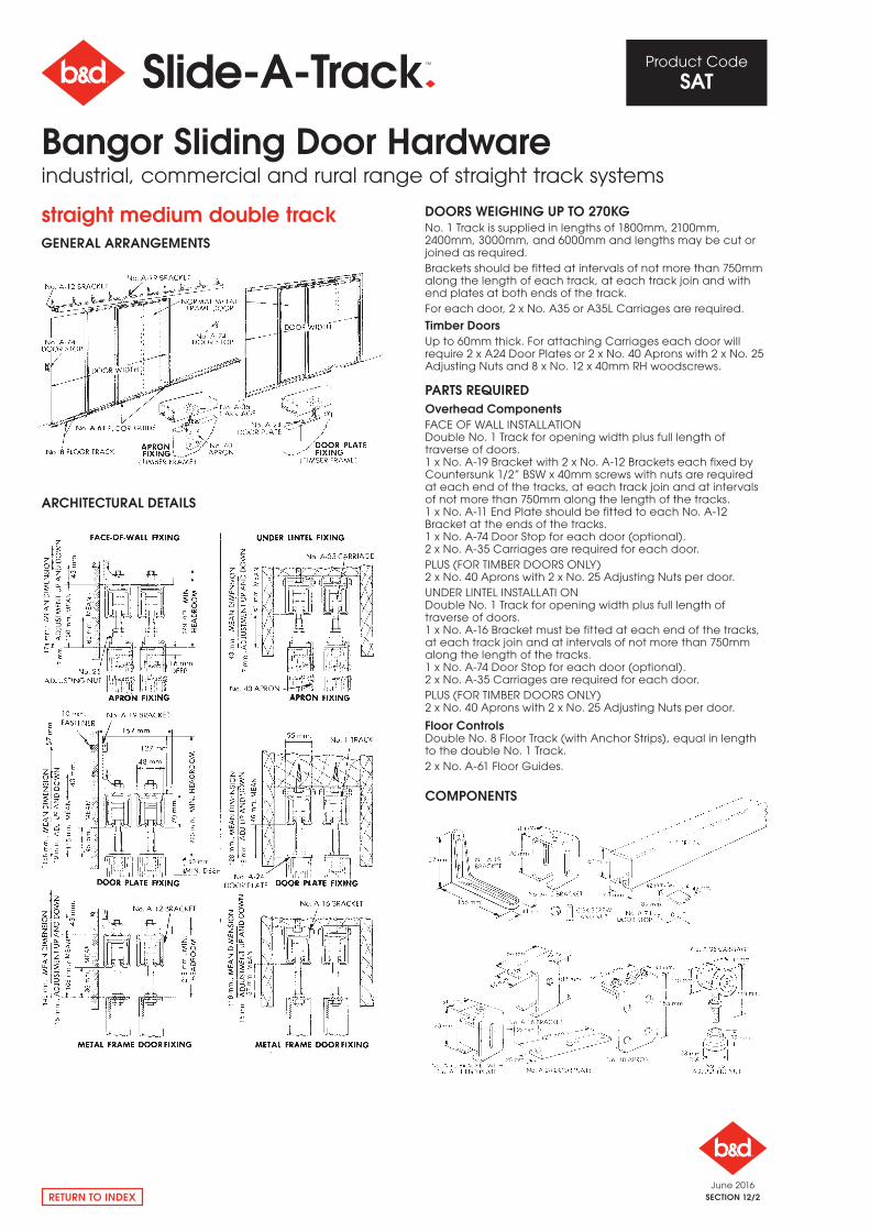
straight medium double trackgENERAl ARRANgEmENTS
ARCHITECTURAl DETAIlS
COmPONENTS
DOORS WEIgHINg UP TO 270kgNo. 1 Track is supplied in lengths of 1800mm, 2100mm, 2400mm, 3000mm, and 6000mm and lengths may be cut or joined as required.Brackets should be fitted at intervals of not more than 750mm along the length of each track, at each track join and with end plates at both ends of the track.For each door, 2 x No. A35 or A35L Carriages are required.
Timber DoorsUp to 60mm thick. For attaching Carriages each door will require 2 x A24 Door Plates or 2 x No. 40 Aprons with 2 x No. 25 Adjusting Nuts and 8 x No. 12 x 40mm rH woodscrews.
PARTS REQUIREDOverhead ComponentsFACE oF WALL INSTALLATIoNDouble No. 1 Track for opening width plus full length of traverse of doors.1 x No. A-19 Bracket with 2 x No. A-12 Brackets each fixed byCountersunk 1/2” BSW x 40mm screws with nuts are required at each end of the tracks, at each track join and at intervals of not more than 750mm along the length of the tracks.1 x No. A-11 End Plate should be fitted to each No. A-12 Bracket at the ends of the tracks.1 x No. A-74 Door Stop for each door (optional).2 x No. A-35 Carriages are required for each door.PLUS (For TIMBEr DoorS oNLy)2 x No. 40 Aprons with 2 x No. 25 Adjusting Nuts per door.UNDEr LINTEL INSTALLATI oNDouble No. 1 Track for opening width plus full length of traverse of doors.1 x No. A-16 Bracket must be fitted at each end of the tracks, at each track join and at intervals of not more than 750mm along the length of the tracks.1 x No. A-74 Door Stop for each door (optional).2 x No. A-35 Carriages are required for each door.PLUS (For TIMBEr DoorS oNLy)2 x No. 40 Aprons with 2 x No. 25 Adjusting Nuts per door.
Floor ControlsDouble No. 8 Floor Track (with Anchor Strips), equal in length to the double No. 1 Track.2 x No. A-61 Floor Guides.
Bangor Sliding Door Hardwareindustrial, commercial and rural range of straight track systems
June 2016SECTION 12/3
Product Code
SAT
RETURN TO INDEX
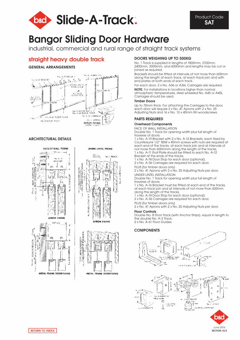
straight heavy double trackgENERAl ARRANgEmENTS
ARCHITECTURAl DETAIlS
DOORS WEIgHINg UP TO 500kgNo. 1 Track is supplied in lengths of 1800mm, 2100mm, 2400mm, 3000mm, and 6000mm and lengths may be cut or joined as required.Brackets should be fitted at intervals of not more than 600mm along the length of each track, at each track join and with end plates at both ends of each track.For each door, 2 x No. A36 or A36L Carriages are required.NOTE: For installations in locations higher than normal atmospheric temperatures, steel wheeled No. A45 or A45L Carriages should be used.
Timber DoorsUp to 70mm thick. For attaching the Carriages to the door, each door will require 2 x No. 41 Aprons with 2 x No. 25 Adjusting Nuts and 16 x No. 12 x 40mm rH woodscrews.
PARTS REQUIREDOverhead ComponentsFACE oF WALL INSTALLATIoNDouble No. 1 Track for opening width plus full length of traverse of doors.1 x No. A-19 Bracket with 2 x No. A-12 Brackets, each fixed by Countersunk 1/2” BSW x 40mm screws with nuts are required at each end of the tracks, at each track join and at intervals of not more than 600mmm along the length of the tracks.1 x No. A-11 End Plate should be fitted to each No. A-12 Bracket at the ends of the tracks.1 x No. A-74 Door Stop for each door (optional).2 x No. A-36 Carriages are required for each door.PLUS (for timber doors only)2 x No. 41 Aprons with 2 x No. 25 Adjusting Nuts per door.UNDEr LINTEL INSTALLATIoNDouble No. 1 Track for opening width plus full length of traverse of doors.1 x No. A-16 Bracket must be fitted at each end of the tracks, at each track join and at intervals of not more than 600mm along the length of the tracks.1 x No. A-74 Door Stop for each door (optional).2 x No. A-36 Carriages are required for each door.PLUS (for timber doors only)2 x No. 41 Aprons with 2 x No. 25 Adjusting Nuts per door.
Floor ControlsDouble No. 8 Floor Track (with Anchor Strips), equal in length to the double No. A-3 Track.2 x No. A-61 Floor Guides.
COmPONENTS
Bangor Sliding Door Hardwareindustrial, commercial and rural range of straight track systems
June 2016SECTION 12/4
Product Code
SAT
RETURN TO INDEX
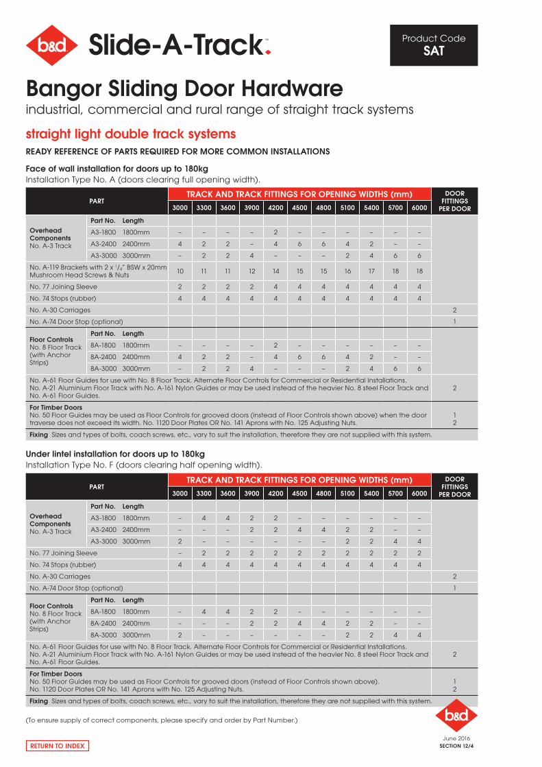
straight light double track systemsREADy REFERENCE OF PARTS REQUIRED FOR mORE COmmON INSTAllATIONS
Face of wall installation for doors up to 180kg Installation Type No. A (doors clearing full opening width).
Under lintel installation for doors up to 180kg Installation Type No. F (doors clearing half opening width).
PARTTRACk AND TRACk FITTINgS FOR OPENINg WIDTHS (mm) DOOR
FITTINgS PER DOOR3000 3300 3600 3900 4200 4500 4800 5100 5400 5700 6000
Overhead ComponentsNo. A-3 Track
Part No. length
A3-1800 1800mm – – – – 2 – – – – – –
A3-2400 2400mm 4 2 2 – 4 6 6 4 2 – –
A3-3000 3000mm – 2 2 4 – – – 2 4 6 6
No. A-119 Brackets with 2 x 1/4” BSW x 20mm Mushroom Head Screws & Nuts
10 11 11 12 14 15 15 16 17 18 18
No. 77 Joining Sleeve 2 2 2 2 4 4 4 4 4 4 4
No. 74 Stops (rubber) 4 4 4 4 4 4 4 4 4 4 4
No. A-30 Carriages 2
No. A-74 Door Stop (optional) 1
Floor ControlsNo. 8 Floor Track (with Anchor Strips)
Part No. length
8A-1800 1800mm – – – – 2 – – – – – –
8A-2400 2400mm 4 2 2 – 4 6 6 4 2 – –
8A-3000 3000mm – 2 2 4 – – – 2 4 6 6
No. A-61 Floor Guides for use with No. 8 Floor Track. Alternate Floor Controls for Commercial or residential Installations.No. A-21 Aluminium Floor Track with No. A-161 Nylon Guides or may be used instead of the heavier No. 8 steel Floor Track and No. A-61 Floor Guides.
2
For Timber DoorsNo. 50 Floor Guides may be used as Floor Controls for grooved doors (instead of Floor Controls shown above) when the door traverse does not exceed its width. No. 1120 Door Plates or No. 141 Aprons with No. 125 Adjusting Nuts.
12
Fixing Sizes and types of bolts, coach screws, etc., vary to suit the installation, therefore they are not supplied with this system.
PARTTRACk AND TRACk FITTINgS FOR OPENINg WIDTHS (mm) DOOR
FITTINgS PER DOOR3000 3300 3600 3900 4200 4500 4800 5100 5400 5700 6000
Overhead ComponentsNo. A-3 Track
Part No. length
A3-1800 1800mm – 4 4 2 2 – – – – – –
A3-2400 2400mm – – – 2 2 4 4 2 2 – –
A3-3000 3000mm 2 – – – – – – 2 2 4 4
No. 77 Joining Sleeve – 2 2 2 2 2 2 2 2 2 2
No. 74 Stops (rubber) 4 4 4 4 4 4 4 4 4 4 4
No. A-30 Carriages 2
No. A-74 Door Stop (optional) 1
Floor ControlsNo. 8 Floor Track (with Anchor Strips)
Part No. length
8A-1800 1800mm – 4 4 2 2 – – – – – –
8A-2400 2400mm – – – 2 2 4 4 2 2 – –
8A-3000 3000mm 2 – – – – – – 2 2 4 4
No. A-61 Floor Guides for use with No. 8 Floor Track. Alternate Floor Controls for Commercial or residential Installations.No. A-21 Aluminium Floor Track with No. A-161 Nylon Guides or may be used instead of the heavier No. 8 steel Floor Track and No. A-61 Floor Guides.
2
For Timber DoorsNo. 50 Floor Guides may be used as Floor Controls for grooved doors (instead of Floor Controls shown above).No. 1120 Door Plates or No. 141 Aprons with No. 125 Adjusting Nuts.
12
Fixing Sizes and types of bolts, coach screws, etc., vary to suit the installation, therefore they are not supplied with this system.
(To ensure supply of correct components, please specify and order by Part Number.)
Bangor Sliding Door Hardwareindustrial, commercial and rural range of straight track systems
June 2016SECTION 12/5
Product Code
SAT
RETURN TO INDEX
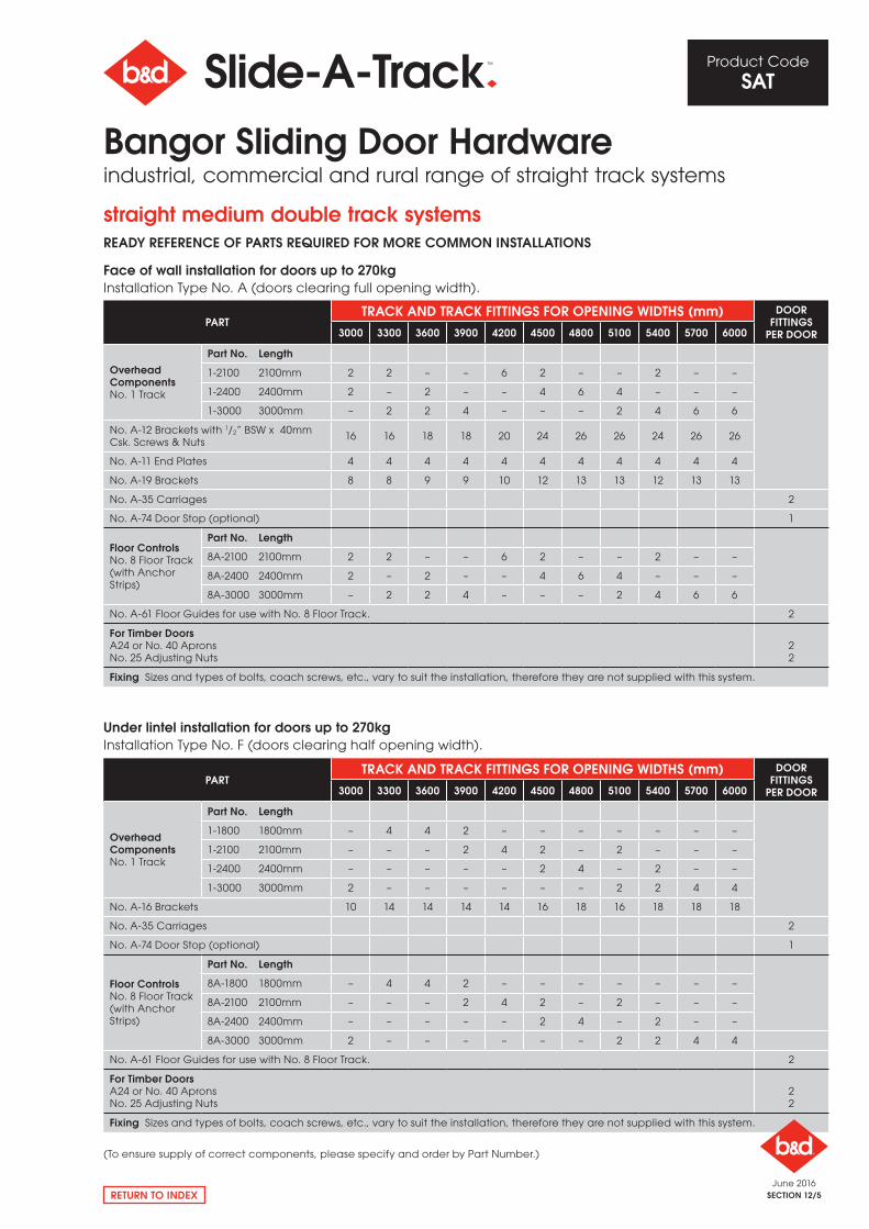
straight medium double track systemsREADy REFERENCE OF PARTS REQUIRED FOR mORE COmmON INSTAllATIONS
Face of wall installation for doors up to 270kg Installation Type No. A (doors clearing full opening width).
Under lintel installation for doors up to 270kg Installation Type No. F (doors clearing half opening width).
(To ensure supply of correct components, please specify and order by Part Number.)
PARTTRACk AND TRACk FITTINgS FOR OPENINg WIDTHS (mm) DOOR
FITTINgS PER DOOR3000 3300 3600 3900 4200 4500 4800 5100 5400 5700 6000
Overhead ComponentsNo. 1 Track
Part No. length
1-1800 1800mm – 4 4 2 – – – – – – –
1-2100 2100mm – – – 2 4 2 – 2 – – –
1-2400 2400mm – – – – – 2 4 – 2 – –
1-3000 3000mm 2 – – – – – – 2 2 4 4
No. A-16 Brackets 10 14 14 14 14 16 18 16 18 18 18
No. A-35 Carriages 2
No. A-74 Door Stop (optional) 1
Floor ControlsNo. 8 Floor Track (with Anchor Strips)
Part No. length
8A-1800 1800mm – 4 4 2 – – – – – – –
8A-2100 2100mm – – – 2 4 2 – 2 – – –
8A-2400 2400mm – – – – – 2 4 – 2 – –
8A-3000 3000mm 2 – – – – – – 2 2 4 4
No. A-61 Floor Guides for use with No. 8 Floor Track. 2
For Timber DoorsA24 or No. 40 ApronsNo. 25 Adjusting Nuts
22
Fixing Sizes and types of bolts, coach screws, etc., vary to suit the installation, therefore they are not supplied with this system.
PARTTRACk AND TRACk FITTINgS FOR OPENINg WIDTHS (mm) DOOR
FITTINgS PER DOOR3000 3300 3600 3900 4200 4500 4800 5100 5400 5700 6000
Overhead ComponentsNo. 1 Track
Part No. length
1-2100 2100mm 2 2 – – 6 2 – – 2 – –
1-2400 2400mm 2 – 2 – – 4 6 4 – – –
1-3000 3000mm – 2 2 4 – – – 2 4 6 6
No. A-12 Brackets with 1/2” BSW x 40mm Csk. Screws & Nuts
16 16 18 18 20 24 26 26 24 26 26
No. A-11 End Plates 4 4 4 4 4 4 4 4 4 4 4
No. A-19 Brackets 8 8 9 9 10 12 13 13 12 13 13
No. A-35 Carriages 2
No. A-74 Door Stop (optional) 1
Floor ControlsNo. 8 Floor Track (with Anchor Strips)
Part No. length
8A-2100 2100mm 2 2 – – 6 2 – – 2 – –
8A-2400 2400mm 2 – 2 – – 4 6 4 – – –
8A-3000 3000mm – 2 2 4 – – – 2 4 6 6
No. A-61 Floor Guides for use with No. 8 Floor Track. 2
For Timber DoorsA24 or No. 40 ApronsNo. 25 Adjusting Nuts
22
Fixing Sizes and types of bolts, coach screws, etc., vary to suit the installation, therefore they are not supplied with this system.
Bangor Sliding Door Hardwareindustrial, commercial and rural range of straight track systems
June 2016SECTION 12/6
Product Code
SAT
RETURN TO INDEX
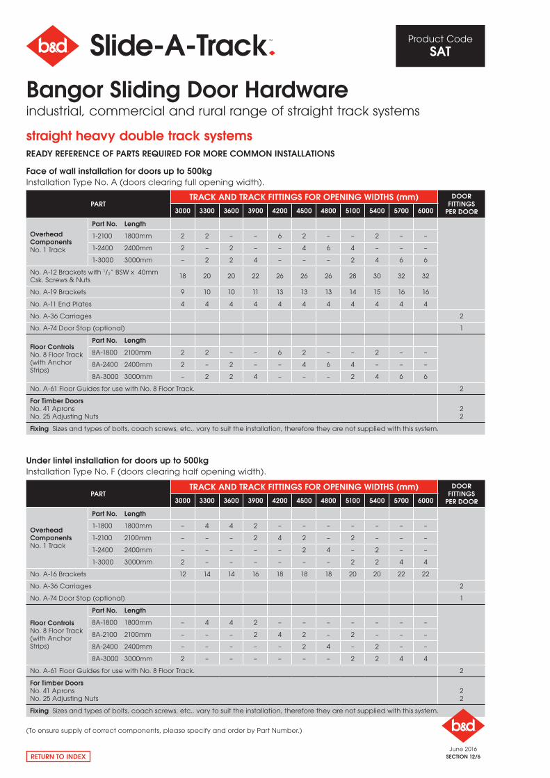
straight heavy double track systemsREADy REFERENCE OF PARTS REQUIRED FOR mORE COmmON INSTAllATIONS
Face of wall installation for doors up to 500kg Installation Type No. A (doors clearing full opening width).
Under lintel installation for doors up to 500kg Installation Type No. F (doors clearing half opening width).
PARTTRACk AND TRACk FITTINgS FOR OPENINg WIDTHS (mm) DOOR
FITTINgS PER DOOR3000 3300 3600 3900 4200 4500 4800 5100 5400 5700 6000
Overhead ComponentsNo. 1 Track
Part No. length
1-2100 1800mm 2 2 – – 6 2 – – 2 – –
1-2400 2400mm 2 – 2 – – 4 6 4 – – –
1-3000 3000mm – 2 2 4 – – – 2 4 6 6
No. A-12 Brackets with 1/2” BSW x 40mm Csk. Screws & Nuts
18 20 20 22 26 26 26 28 30 32 32
No. A-19 Brackets 9 10 10 11 13 13 13 14 15 16 16
No. A-11 End Plates 4 4 4 4 4 4 4 4 4 4 4
No. A-36 Carriages 2
No. A-74 Door Stop (optional) 1
Floor ControlsNo. 8 Floor Track (with Anchor Strips)
Part No. length
8A-1800 2100mm 2 2 – – 6 2 – – 2 – –
8A-2400 2400mm 2 – 2 – – 4 6 4 – – –
8A-3000 3000mm – 2 2 4 – – – 2 4 6 6
No. A-61 Floor Guides for use with No. 8 Floor Track. 2
For Timber DoorsNo. 41 ApronsNo. 25 Adjusting Nuts
22
Fixing Sizes and types of bolts, coach screws, etc., vary to suit the installation, therefore they are not supplied with this system.
PARTTRACk AND TRACk FITTINgS FOR OPENINg WIDTHS (mm) DOOR
FITTINgS PER DOOR3000 3300 3600 3900 4200 4500 4800 5100 5400 5700 6000
Overhead ComponentsNo. 1 Track
Part No. length
1-1800 1800mm – 4 4 2 – – – – – – –
1-2100 2100mm – – – 2 4 2 – 2 – – –
1-2400 2400mm – – – – – 2 4 – 2 – –
1-3000 3000mm 2 – – – – – – 2 2 4 4
No. A-16 Brackets 12 14 14 16 18 18 18 20 20 22 22
No. A-36 Carriages 2
No. A-74 Door Stop (optional) 1
Floor ControlsNo. 8 Floor Track (with Anchor Strips)
Part No. length
8A-1800 1800mm – 4 4 2 – – – – – – –
8A-2100 2100mm – – – 2 4 2 – 2 – – –
8A-2400 2400mm – – – – – 2 4 – 2 – –
8A-3000 3000mm 2 – – – – – – 2 2 4 4
No. A-61 Floor Guides for use with No. 8 Floor Track. 2
For Timber DoorsNo. 41 ApronsNo. 25 Adjusting Nuts
22
Fixing Sizes and types of bolts, coach screws, etc., vary to suit the installation, therefore they are not supplied with this system.
Bangor Sliding Door Hardwareindustrial, commercial and rural range of straight track systems
(To ensure supply of correct components, please specify and order by Part Number.)
June 2016SECTION 12/7
Product Code
SAT
RETURN TO INDEX
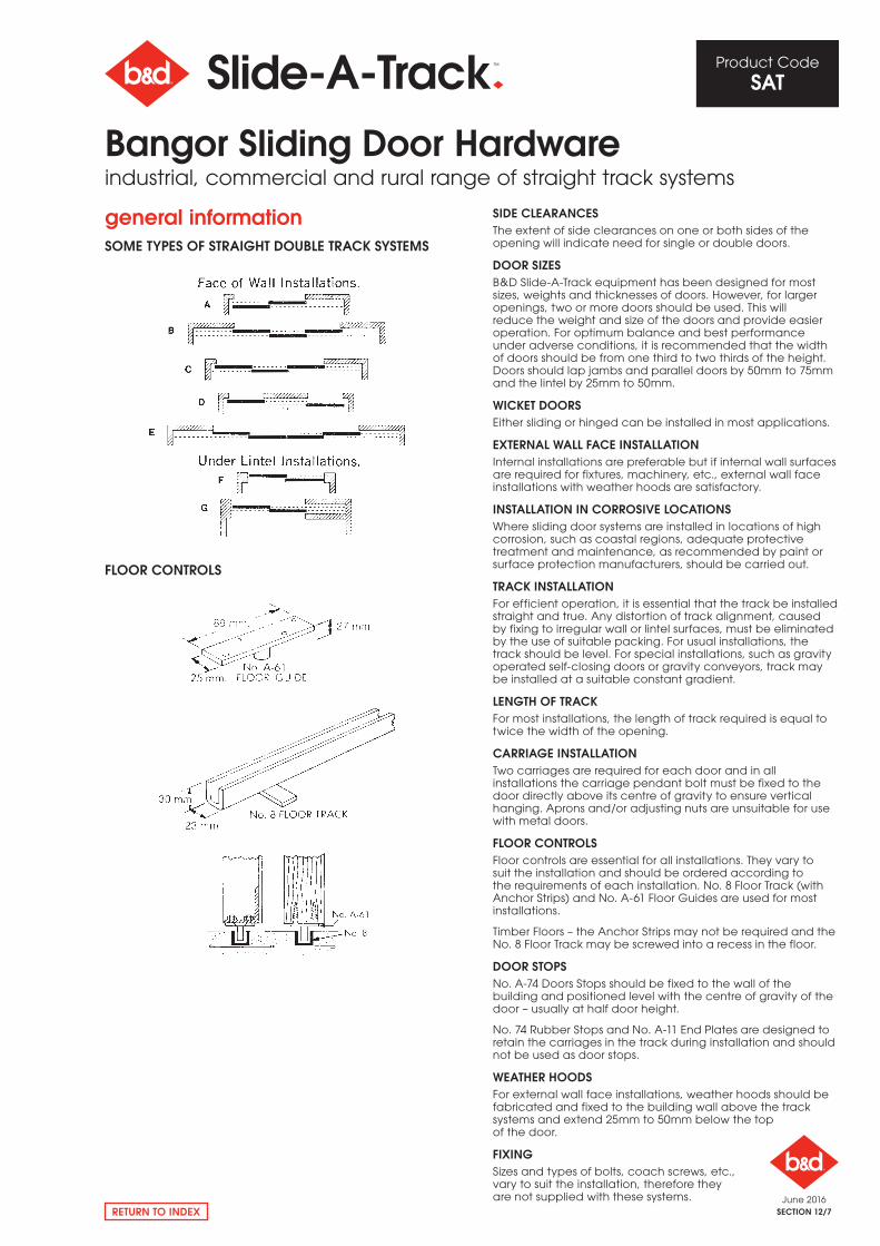
general informationSOmE TyPES OF STRAIgHT DOUBlE TRACk SySTEmS
FlOOR CONTROlS
SIDE ClEARANCESThe extent of side clearances on one or both sides of the opening will indicate need for single or double doors.
DOOR SIzESB&D Slide-A-Track equipment has been designed for most sizes, weights and thicknesses of doors. However, for larger openings, two or more doors should be used. This will reduce the weight and size of the doors and provide easier operation. For optimum balance and best performance under adverse conditions, it is recommended that the width of doors should be from one third to two thirds of the height. Doors should lap jambs and parallel doors by 50mm to 75mm and the lintel by 25mm to 50mm.
WICkET DOORSEither sliding or hinged can be installed in most applications.
EXTERNAl WAll FACE INSTAllATIONInternal installations are preferable but if internal wall surfaces are required for fixtures, machinery, etc., external wall face installations with weather hoods are satisfactory.
INSTAllATION IN CORROSIvE lOCATIONSWhere sliding door systems are installed in locations of high corrosion, such as coastal regions, adequate protective treatment and maintenance, as recommended by paint or surface protection manufacturers, should be carried out.
TRACk INSTAllATIONFor efficient operation, it is essential that the track be installed straight and true. Any distortion of track alignment, caused by fixing to irregular wall or lintel surfaces, must be eliminated by the use of suitable packing. For usual installations, the track should be level. For special installations, such as gravity operated self-closing doors or gravity conveyors, track may be installed at a suitable constant gradient.
lENgTH OF TRACkFor most installations, the length of track required is equal to twice the width of the opening.
CARRIAgE INSTAllATIONTwo carriages are required for each door and in all installations the carriage pendant bolt must be fixed to the door directly above its centre of gravity to ensure vertical hanging. Aprons and/or adjusting nuts are unsuitable for use with metal doors.
FlOOR CONTROlSFloor controls are essential for all installations. They vary to suit the installation and should be ordered according to the requirements of each installation. No. 8 Floor Track (with Anchor Strips) and No. A-61 Floor Guides are used for most installations.
Timber Floors – the Anchor Strips may not be required and the No. 8 Floor Track may be screwed into a recess in the floor.
DOOR STOPSNo. A-74 Doors Stops should be fixed to the wall of the building and positioned level with the centre of gravity of the door – usually at half door height.
No. 74 rubber Stops and No. A-11 End Plates are designed to retain the carriages in the track during installation and should not be used as door stops.
WEATHER HOODSFor external wall face installations, weather hoods should be fabricated and fixed to the building wall above the track systems and extend 25mm to 50mm below the top of the door.
FIXINgSizes and types of bolts, coach screws, etc., vary to suit the installation, therefore they are not supplied with these systems.
Bangor Sliding Door Hardwareindustrial, commercial and rural range of straight track systems
June 2016SECTION 12/8
Product Code
SAT
RETURN TO INDEX
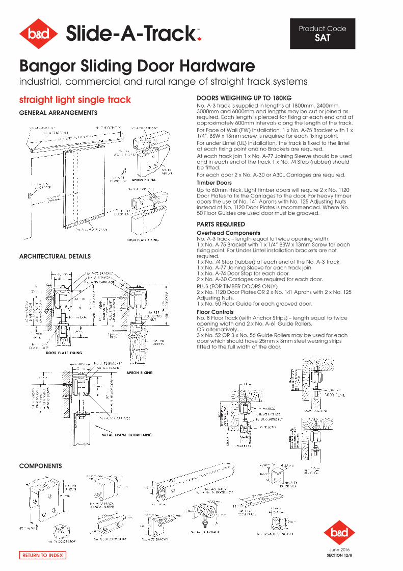
straight light single trackgENERAl ARRANgEmENTS
ARCHITECTURAl DETAIlS
COmPONENTS
DOORS WEIgHINg UP TO 180kgNo. A-3 track is supplied in lengths at 1800mm, 2400mm, 3000mm and 6000mm and lengths may be cut or joined as required. Each length is pierced for fixing at each end and at approximately 600mm intervals along the length of the track.For Face of Wall (FW) installation, 1 x No. A-75 Bracket with 1 x 1/4”, BSW x 13mm screw is required for each fixing point.For under Lintel (UL) Installation, the track is fixed to the lintel at each fixing point and no Brackets are required.At each track join 1 x No. A-77 Joining Sleeve should be used and in each end of the track 1 x No. 74 Stop (rubber) should be fitted. For each door 2 x No. A-30 or A30L Carriages are required.
Timber DoorsUp to 60mm thick. Light timber doors will require 2 x No. 1120 Door Plates to fix the Carriages to the door, For heavy timber doors the use of No. 141 Aprons with No. 125 Adjusting Nuts instead of No. 1120 Door Plates is recommended. Where No. 50 Floor Guides are used door must be grooved.
PARTS REQUIREDOverhead ComponentsNo. A-3 Track – length equal to twice opening width.1 x No. A·75 Bracket with 1 x 1/4” BSW x 13mm Screw for each fixing point. For Under Lintel installation brackets are not required.1 x No. 74 Stop (rubber) at each end of the No. A-3 Track.1 x No. A-77 Joining Sleeve for each track join.1 x No. A-74 Door Stop for each door.2 x No. A-30 Carriages are required for each door. PLUS (For TIMBEr DoorS oNLy) 2 x No. 1120 Door Plates or 2 x No. 141 Aprons with 2 x No. 125 Adjusting Nuts.1 x No. 50 Floor Guide for each grooved door.
Floor ControlsNo. 8 Floor Track (with Anchor Strips) – length equal to twiceopening width and 2 x No. A-61 Guide rollers.or alternatively....3 x No. 52 or 3 x No. 56 Guide rollers may be used for eachdoor which should have 25mm x 3mm steel wearing stripsfitted to the full width of the door.
Bangor Sliding Door Hardwareindustrial, commercial and rural range of straight track systems
June 2016SECTION 12/9
Product Code
SAT
RETURN TO INDEX
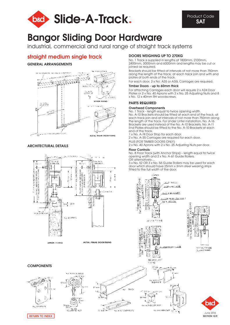
straight medium single trackgENERAl ARRANgEmENTS
ARCHITECTURAl DETAIlS
COmPONENTS
DOORS WEIgHINg UP TO 270kgNo. 1 Track is supplied in lengths of 1800mm, 2100mm, 2400mm, 3000mm and 6000mm and lengths may be cut or joined as required.Brackets should be fitted at intervals of not more than 750mm along the length of the track, at each track join and with end plates at both ends of the track.For each door, 2 x No. A35 or A35L Carriages are required.
Timber Doors - up to 60mm thick For attaching Carriages each door will require 2 x A24 Door Plates or 2 x No. 40 Aprons with 2 x No. 25 Adjusting Nuts and 8 x No. 12 x 40mm rH woodscrews.
PARTS REQUIREDOverhead ComponentsNo. 1 Track - length equal to twice opening width.No. A-10 Brackets should be fitted at each end of the track, at each track join and at intervals of not more than 750mm along the length of the track. For Under Lintel installation, No. A-16 Brackets are used instead of the No. A-10 Brackets. No. A-11 End Plates should be fitted to the No. A-10 Brackets at each end of the track.1 x No. A-74 Door Stop for each door.2 x No. A-35 Carriages are required for each door.PLUS (For TIMBEr DoorS oNLy) 2 x No. 40 Aprons with 2 x No. 25 Adjusting Nuts per door.
Floor ControlsNo. 8 Floor Track (with Anchor Strips) – length equal to twice opening width and 2 x No. A-61 Guide rollers. or alternatively....3 x No. 52 or 3 x No. 56 Guide rollers may be used for each door which should have 25mm x 3mm steel wearing strips fitted to the full width of the door.
Bangor Sliding Door Hardwareindustrial, commercial and rural range of straight track systems
June 2016SECTION 12/10
Product Code
SAT
RETURN TO INDEX
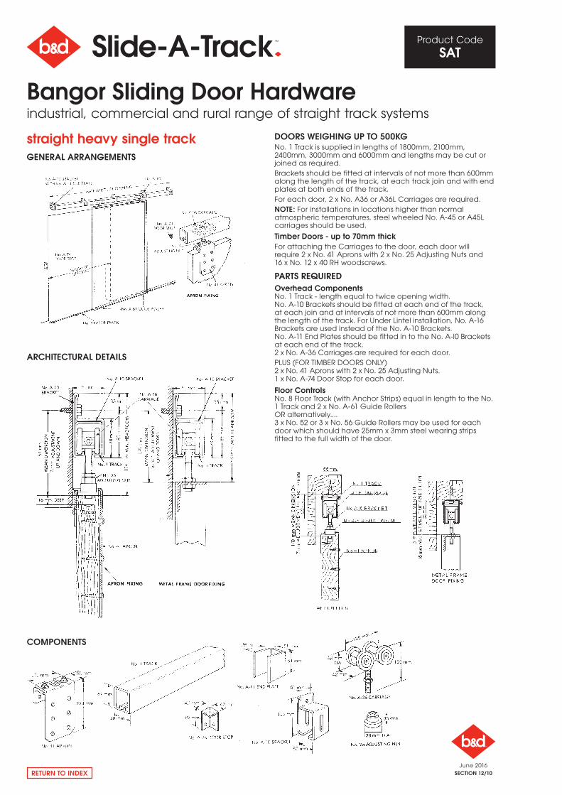
straight heavy single trackgENERAl ARRANgEmENTS
ARCHITECTURAl DETAIlS
COmPONENTS
DOORS WEIgHINg UP TO 500kgNo. 1 Track is supplied in lengths of 1800mm, 2100mm, 2400mm, 3000mm and 6000mm and lengths may be cut or joined as required.Brackets should be fitted at intervals of not more than 600mm along the length of the track, at each track join and with end plates at both ends of the track.For each door, 2 x No. A36 or A36L Carriages are required.NOTE: For installations in locations higher than normal atmospheric temperatures, steel wheeled No. A-45 or A45L carriages should be used.
Timber Doors - up to 70mm thick For attaching the Carriages to the door, each door will require 2 x No. 41 Aprons with 2 x No. 25 Adjusting Nuts and 16 x No. 12 x 40 rH woodscrews.
PARTS REQUIREDOverhead ComponentsNo. 1 Track - length equal to twice opening width.No. A-10 Brackets should be fitted at each end of the track, at each join and at intervals of not more than 600mm along the length of the track. For Under Lintel installation, No. A-16 Brackets are used instead of the No. A-10 Brackets.No. A-11 End Plates should be fitted in to the No. A-l0 Brackets at each end of the track.2 x No. A-36 Carriages are required for each door.PLUS (For TIMBEr DoorS oNLy) 2 x No. 41 Aprons with 2 x No. 25 Adjusting Nuts.1 x No. A-74 Door Stop for each door.
Floor ControlsNo. 8 Floor Track (with Anchor Strips) equal in length to the No. 1 Track and 2 x No. A-61 Guide rollersor alternatively....3 x No. 52 or 3 x No. 56 Guide rollers may be used for each door which should have 25mm x 3mm steel wearing strips fitted to the full width of the door.
Bangor Sliding Door Hardwareindustrial, commercial and rural range of straight track systems
June 2016SECTION 12/11
Product Code
SAT
RETURN TO INDEX
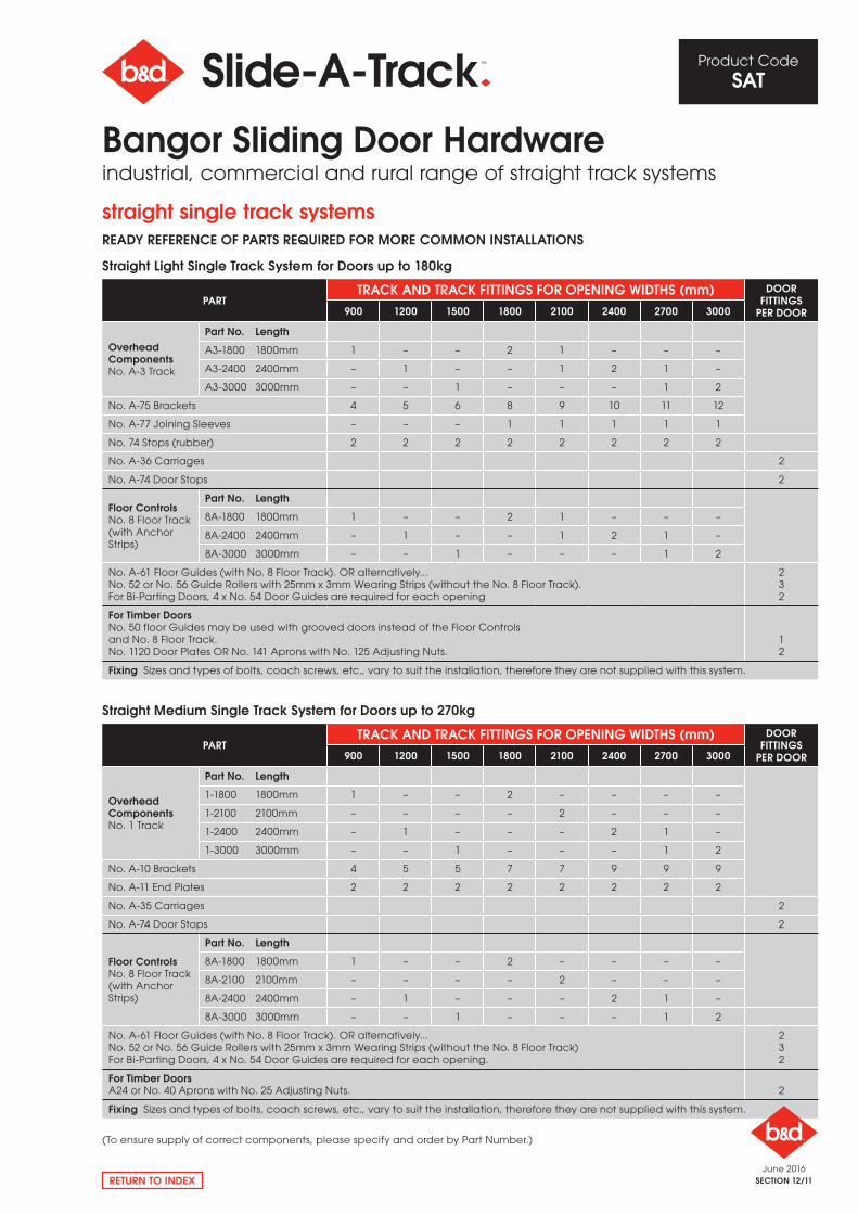
straight single track systemsREADy REFERENCE OF PARTS REQUIRED FOR mORE COmmON INSTAllATIONS
Straight light Single Track System for Doors up to 180kg
PARTTRACk AND TRACk FITTINgS FOR OPENINg WIDTHS (mm) DOOR
FITTINgS PER DOOR900 1200 1500 1800 2100 2400 2700 3000
Overhead ComponentsNo. A-3 Track
Part No. length
A3-1800 1800mm 1 – – 2 1 – – –
A3-2400 2400mm – 1 – – 1 2 1 –
A3-3000 3000mm – – 1 – – – 1 2
No. A-75 Brackets 4 5 6 8 9 10 11 12
No. A-77 Joining Sleeves – – – 1 1 1 1 1
No. 74 Stops (rubber) 2 2 2 2 2 2 2 2
No. A-36 Carriages 2
No. A-74 Door Stops 2
Floor ControlsNo. 8 Floor Track (with Anchor Strips)
Part No. length
8A-1800 1800mm 1 – – 2 1 – – –
8A-2400 2400mm – 1 – – 1 2 1 –
8A-3000 3000mm – – 1 – – – 1 2
No. A-61 Floor Guides (with No. 8 Floor Track). or alternatively... No. 52 or No. 56 Guide rollers with 25mm x 3mm Wearing Strips (without the No. 8 Floor Track).For Bi-Parting Doors, 4 x No. 54 Door Guides are required for each opening
232
For Timber DoorsNo. 50 floor Guides may be used with grooved doors instead of the Floor Controls and No. 8 Floor Track.No. 1120 Door Plates or No. 141 Aprons with No. 125 Adjusting Nuts.
12
Fixing Sizes and types of bolts, coach screws, etc., vary to suit the installation, therefore they are not supplied with this system.
Straight medium Single Track System for Doors up to 270kg
PARTTRACk AND TRACk FITTINgS FOR OPENINg WIDTHS (mm) DOOR
FITTINgS PER DOOR900 1200 1500 1800 2100 2400 2700 3000
Overhead ComponentsNo. 1 Track
Part No. length
1-1800 1800mm 1 – – 2 – – – –
1-2100 2100mm – – – – 2 – – –
1-2400 2400mm – 1 – – – 2 1 –
1-3000 3000mm – – 1 – – – 1 2
No. A-10 Brackets 4 5 5 7 7 9 9 9
No. A-11 End Plates 2 2 2 2 2 2 2 2
No. A-35 Carriages 2
No. A-74 Door Stops 2
Floor ControlsNo. 8 Floor Track (with Anchor Strips)
Part No. length
8A-1800 1800mm 1 – – 2 – – – –
8A-2100 2100mm – – – – 2 – – –
8A-2400 2400mm – 1 – – – 2 1 –
8A-3000 3000mm – – 1 – – – 1 2
No. A-61 Floor Guides (with No. 8 Floor Track). or alternatively... No. 52 or No. 56 Guide rollers with 25mm x 3mm Wearing Strips (without the No. 8 Floor Track)For Bi-Parting Doors, 4 x No. 54 Door Guides are required for each opening.
232
For Timber DoorsA24 or No. 40 Aprons with No. 25 Adjusting Nuts. 2
Fixing Sizes and types of bolts, coach screws, etc., vary to suit the installation, therefore they are not supplied with this system.
Bangor Sliding Door Hardwareindustrial, commercial and rural range of straight track systems
(To ensure supply of correct components, please specify and order by Part Number.)
June 2016SECTION 12/12
Product Code
SAT
RETURN TO INDEX
straight single track systemsREADy REFERENCE OF PARTS REQUIRED FOR mORE COmmON INSTAllATIONS
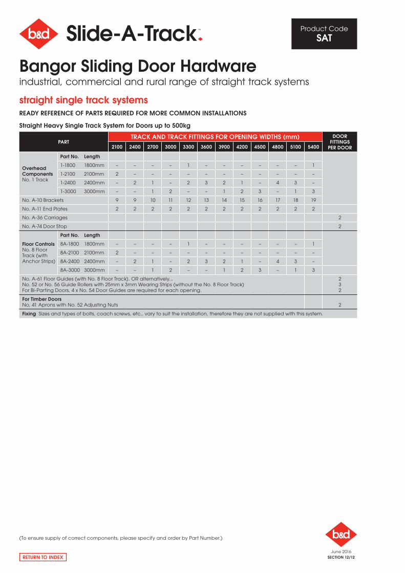
Straight Heavy Single Track System for Doors up to 500kg
PARTTRACk AND TRACk FITTINgS FOR OPENINg WIDTHS (mm) DOOR
FITTINgS PER DOOR2100 2400 2700 3000 3300 3600 3900 4200 4500 4800 5100 5400
Overhead ComponentsNo. 1 Track
Part No. length
1-1800 1800mm – – – – 1 – – – – – – 1
1-2100 2100mm 2 – – – – – – – – – – –
1-2400 2400mm – 2 1 – 2 3 2 1 – 4 3 –
1-3000 3000mm – – 1 2 – – 1 2 3 – 1 3
No. A-10 Brackets 9 9 10 11 12 13 14 15 16 17 18 19
No. A-11 End Plates 2 2 2 2 2 2 2 2 2 2 2 2
No. A-36 Carriages 2
No. A-74 Door Stop 2
Floor ControlsNo. 8 Floor Track (with Anchor Strips)
Part No. length
8A-1800 1800mm – – – – 1 – – – – – – 1
8A-2100 2100mm 2 – – – – – – – – – – –
8A-2400 2400mm – 2 1 – 2 3 2 1 – 4 3 –
8A-3000 3000mm – – 1 2 – – 1 2 3 – 1 3
No. A-61 Floor Guides (with No. 8 Floor Track). or alternatively...No. 52 or No. 56 Guide rollers with 25mm x 3mm Wearing Strips (without the No. 8 Floor Track)For Bi-Parting Doors, 4 x No. 54 Door Guides are required for each opening.
232
For Timber DoorsNo, 41 Aprons with No. 52 Adjusting Nuts 2
Fixing Sizes and types of bolts, coach screws, etc., vary to suit the installation, therefore they are not supplied with this system.
Bangor Sliding Door Hardwareindustrial, commercial and rural range of straight track systems
(To ensure supply of correct components, please specify and order by Part Number.)
June 2016SECTION 12/13
Product Code
SAT
RETURN TO INDEX
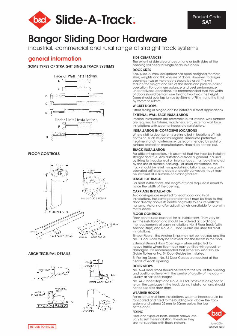
general informationSOmE TyPES OF STRAIgHT SINglE TRACk SySTEmS
FlOOR CONTROlS
ARCHITECTURAl DETAIlS
SIDE ClEARANCESThe extent of side clearances on one or both sides of the opening will need for single or double doors.
DOOR SIzESB&D Slide-A-Track equipment has been designed for most sizes, weights and thicknesses of doors. However, for larger openings, two or more doors should be used. This will reduce the weight and size of the doors and provide easier operation. For optimum balance and best performance under adverse conditions, it is recommended that the width of doors should be from one third to two thirds the height. Doors should over lap jambs by 50mm to 75mm and the lintel by 25mm to 50mm.
WICkET DOORSEither sliding or hinged can be installed in most applications.
EXTERNAl WAll FACE INSTAllATIONInternal installations are preferable but if internal wall surfaces are required for fixtures, machinery. etc., external wall face installations with weather hoods are satisfactory.
INSTAllATION IN CORROSIvE lOCATIONSWhere sliding door systems are installed in locations of high corrosion, such as coastal regions, adequate protective treatment and maintenance, as recommended by paint or surface protection manufacturers, should be carried out.
TRACk INSTAllATIONFor efficient operation, it is essential that the track be installed straight and true. Any distortion of track alignment, caused by fixing to irregular wall or lintel surfaces, must be eliminated by the use of suitable packing. For usual installations, the track should be level. For special installations, such as gravity operated self-closing doors or gravity conveyors, track may be installed at a suitable constant gradient.
lENgTH OF TRACkFor most installations, the length of track required is equal to twice the width of the opening.
CARRIAgE INSTAllATIONTwo carriages are required for each door and in all installations, the carriage pendant bolt must be fixed to the door directly above its centre of gravity to ensure vertical hanging. Aprons and/or adjusting nuts unsuitable for use with metal doors.
FlOOR CONTROlSFloor controls are essential for all installations. They vary to suit the installation and should be ordered according to the requirements of each installation. No. 8 Floor Track (with Anchor Strips) and No. A-61 Floor Guides are used for most installations.Timber Floors – the Anchor Strips may not be required and the No. 8 Floor Track may be screwed into the recess in the floor.External Ground Floor openings – when subjected to heavy traffic where floor track may be filled with gravel, or damaged. it is recommended that either No. 52 or No. 56 Guide rollers or No. 54 Door Guides be Installed.Bi-Parting Doors – No. 54 Door Guides are required at the centre of each opening.
DOOR STOPSNo. A-74 Door Stops should be fixed to the wall of the building and positioned level with the centre of gravity of the door – usually at half door height.No. 74 rubber Stops and No. A-11 End Plates are designed to retain the carriages in the track during installation and should not be used as door stops.
WEATHER HOODSFor external wall face installations, weather hoods should be fabricated and fixed to the building wall above the track system and extend 25 mm to 50mm below the top of the door.
FIXINgSizes and types of bolts, coach screws, etc. vary to suit the installation, therefore they are not supplied with these systems.
Bangor Sliding Door Hardwareindustrial, commercial and rural range of straight track systems
June 2016SECTION 12/14
Product Code
SAT
RETURN TO INDEX
notes
Bangor Sliding Door Hardwareindustrial, commercial and rural range of straight track systems