slayt 1 - deukisi.deu.edu.tr/emine.cinar/statics/b17 statics_frames and machines... · members and...
TRANSCRIPT

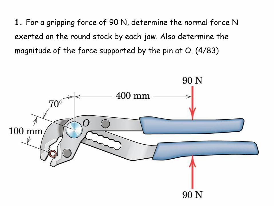
1. For a gripping force of 90 N, determine the normal force N
exerted on the round stock by each jaw. Also determine the
magnitude of the force supported by the pin at O. (4/83)

N
FBD of lower piece
NN
N
MO
360
0)100()400(90
0
+
NO
NOONF
NOONF
yyy
xxx
400
13.21309020sin0
29.338020cos0
360
360
normal force N exerted on the round stock by each jaw and force supported by the pin at O
Ox
Oy
20°

2. The toggle pliers are used for a variety of clamping
purposes. For the handle position given by a = 10° and for a
handle grip P = 150 N, calculate the clamping force FC
produced.
Note that pins
A and D are
symmetric
about the
horizontal
centerline of
the tool.

a = 10°, P = 150 N, calculate the clamping force FC produced. All loading is vertical and symmetric.
FBD of lower handle
B
a
Bcos10 Bsin10
Dy
Dx
NBBMD 46.42530)20(10sin)100(10cos1500 +
NDDBF
DDF
yyy
xxx
46.410301500
000

a = 10°, P = 150 N, calculate the clamping force FC produced. All loading is vertical and symmetric.
FBD of DOC
Dy FC
NFFDM CCyO 82.13670)60()20(0 +
O
C

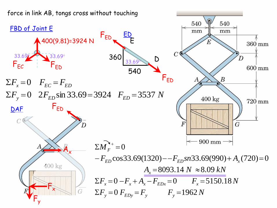
3. Compute the force
in link AB of the
lifting tongs which
cross without
touching.
force in link AB, tongs cross without touching
FBD of Joint E
FED
400(9.81)=3924 N
FEC
DAF
E
D 360
540
33.69° 33.69° 33.69°
NFFFF
NFFAFF
kNNA
AsnFF
M
yyEDyy
xEDxxxx
x
xEDED
F
19620
18.515000
09.814.8093
0)720()990(69.33)1320(69.33cos
0
NFFF
FFF
EDEDy
EDECx
3537392469.33sin20
0
FED
FED
FED
Ax
ED
Fx
Fy

4. The elements of a rear suspension for a front-wheel-drive car are shown in the figure. Determine the magnitude of the force at each joint if the normal force F exerted on the tire has a magnitude of 3600 N. (4/122)

magnitudes of forces at each joint
FCD
Bx
By
a
x
y
09.12280
60tan 1
a
NBFBF
NBFBF
NF
FF
M
yCDyy
xCDxx
CD
CDCD
B
400003600sin0
18560cos0
1898
0)70(sin)305(cos)165(3600
0
a
a
aa
NB 441040001856 22
CD
FCD
FCD
FBD of wheel + BC

NA
NAFAF
NAFAF
NF
F
M
yEFyy
xEFxx
EF
EF
A
455013844330
138404000sin0
433001856cos0
5920
0)350(4000)260(sin
0
22
magnitudes of forces at each joint
Bx
By
x
y
30.65200
435tan 1
FEF
EF
FEF
FEF
Ax
Ay
FBD of AEB
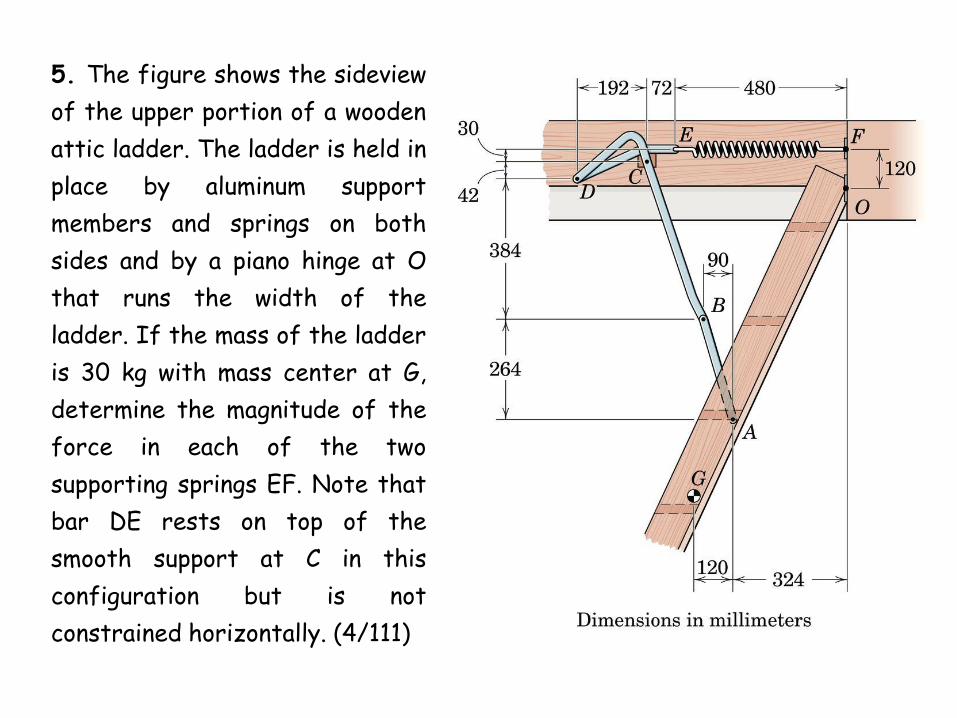
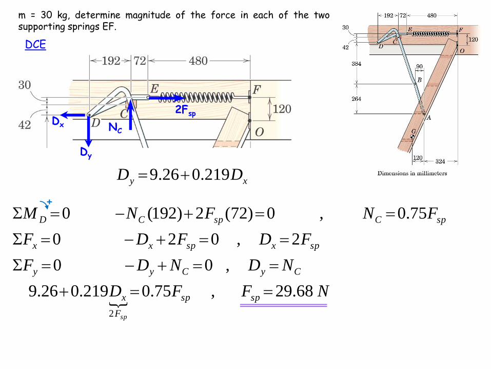
5. The figure shows the sideview
of the upper portion of a wooden
attic ladder. The ladder is held in
place by aluminum support
members and springs on both
sides and by a piano hinge at O
that runs the width of the
ladder. If the mass of the ladder
is 30 kg with mass center at G,
determine the magnitude of the
force in each of the two
supporting springs EF. Note that
bar DE rests on top of the
smooth support at C in this
configuration but is not
constrained horizontally. (4/111)

Piano hinge (or continuous hinge) m = 30 kg, determine magnitude of the force in each of the two supporting springs EF.
GAO
FAB
W=30 (9.81)=294.3 N
Ox
Oy
NFF
FF
M
ABAB
ABAB
O
21.261,2.13066924.500
0)444(3.294
)600(18.71cos)324(18.71sin
0
+
264
90
a
A
B
a 71.18°
a
600
AB
FAB
FAB
A
B

m = 30 kg, determine magnitude of the force in each of the two supporting springs EF.
BCD
Cx
Cy
xy
yx
yx
C
DD
DD
DD
M
219.026.9
1924224.1777
0)192()42()426(18.71cos21.261)138(18.71sin21.261
0
+
FAB
a
Dx
Dy
m = 30 kg, determine magnitude of the force in each of the two supporting springs EF.
DCE
2Fsp
NC
NFFD
NDNDF
FDFDF
FNFNM
spsp
F
x
CyCyy
spxspxx
spCspCD
sp
68.29,75.0219.026.9
,00
2,020
75.0,0)72(2)192(0
2
+
Dx
Dy
xy DD 219.026.9

6. Determine the cutting force F applied by the blade DE to the
bar at G in terms of the force P applied to the handle of the
heavy-duty cutter.
Assume that
the cutting
force F is
perpendicular
to the lower
edge of the
blade DE.
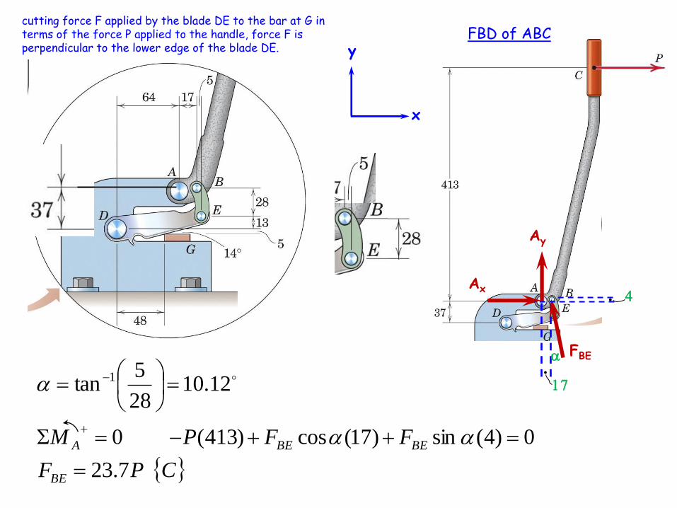
cutting force F applied by the blade DE to the bar at G in terms of the force P applied to the handle, force F is perpendicular to the lower edge of the blade DE.
FBE
a
x
y
FBD of ABC
Ax
Ay
4
17
CPF
FFPM
BE
BEBEA
7.23
0)4(sin)17(cos)413(0
12.1028
5tan 1
aa
a

cutting force F applied by the blade DE to the bar at G in terms of the force P applied to the handle, force F is perpendicular to the lower edge of the blade DE.
FBE=23.7P
a
x
y
FBD of Blade DE
Dx
Dy
86
14°
PF
FFPPM D
4.45
0)5(14sin)48(14cos)13(sin7.23)86(cos7.230
aa
F

7. The design of a hoisting mechanism for the dump truck is shown in the enlarged view. Determine the compression P in the hydraulic cylinder BE and the magnitude of the force supported by the pin at A for the particular position shown, where BA is perpendicular to OAE and link DC is perpendicular to AC. The dump and its load together have a mass of 9 Mg with center of mass at G.
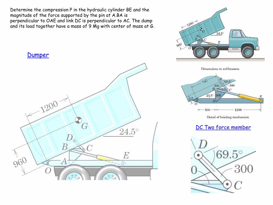
Determine the compression P in the hydraulic cylinder BE and the magnitude of the force supported by the pin at A.BA is perpendicular to OAE and link DC is perpendicular to AC. The dump and its load together have a mass of 9 Mg with center of mass at G.
Dumper
DC Two force member

Determine the compression P in the hydraulic cylinder BE and the magnitude of the force supported by the pin at A.BA is perpendicular to OAE and link DC is perpendicular to AC. The dump and its load together have a mass of 9 Mg with center of mass at G.
ABC
BE Two force member

8. A basketball hoop whose
rim height is adjustable is
shown. The supporting post
ABCD weighs 400 N with the
center of gravity at point C,
and backboard-hoop assembly
weighs 220 N with the center
of gravity at point G. The
height of the rim is adjustable
by means of the screw and
hand crank IJ, where the
screw is vertical. If a person
with 800 N weight hangs on
the rim, determine the
support reactions at D and the
forces supported by all
members. Hint: Member IJ is
a two-force member.
800 N
24
7

mABCD= 400 N (at C), mhoop= 220 N (at G) IJ= two-force member, if a person with 800 N weight hangs on the rim, determine the support reactions at D and the forces supported by all members.
Dx
mNM
M
M
ND
D
F
ND
DF
D
D
D
y
y
y
x
xx
2.1867
0)35.1(768
)3(224)72.0(220
0
1388
0768220400
0
224
02240
220 N
400 N
Dy
MD
800 N
24
7
224 N
768 N
FBD of Entire frame
x
y

mABCD= 400 N (at C), mhoop= 220 N (at G) IJ= two-force member, if a person with 800 N weight hangs on the rim, determine the support reactions at D and the forces supported by all members.
FAE
NF
NF
FFF
NF
FFF
NF
NFF
F
NF
F
M
y
yAEyy
x
xAExx
AE
AEy
AEx
AEy
AEx
AEx
F
2243)1992()1031(
1992
07682200
1031
02240
1584)1004()1225(
1004,5
4
60.0
48.0
1255
0)75.0(768)12.0(22048.0
0
22
22
FAEx
220 N
FAEy
800 N
24
7
224 N
768 N
Fx
Fy
FBD of EFGH
x
y

mABCD= 400 N (at C), mhoop= 220 N (at G) IJ= two-force member, if a person with 800 N weight hangs on the rim, determine the support reactions at D and the forces supported by all members.
FIJ
NB
NBFBFF
NFBFBF
NF
FFF
M
yyyIJy
xxxxx
IJ
yxIJ
B
6740)6661()1031(
666100
103100
4669
0)60.0()48.0(15.0
0
22
Fx
Fy
FBD of IBF
Bx
By
IJ two force member
FIJ
FIJ
x
y

9. The figure shows a wheel puller which is designed to remove a V-belt pulley P from its tight-fitting shaft S by tightening of the central screw. If the pulley starts to slide off the shaft when the compression in the screw has reached 1.2 kN, calculate the magnitude of the force supported by the each jaw at A. The adjusting screws D support horizontal force and keep the side arms parallel with the central screw.

compression in the screw =1.2 kN, calculate the magnitude of the force supported by the each jaw at A, adjusting screws D support horizontal force
FCB
x
y
kNFF
kNFFFF
F
F
FFF
FF
FFF
EHCB
EHxCBxEHyCBy
CBx
CBy
EHxCBxx
EHyCBy
EHyCByy
85.0
6.0
145tan
0
2.1
02.10
1.2 kN
FEH
E
H
FEHx
FEHy
FCBx
FCBy
45°
45°
FCBy
FCBy
FCBx
FCBx
FCB
FCB
CB
EC

compression in the screw =1.2 kN, calculate the magnitude of the force supported by the each jaw at A, adjusting screws D support horizontal force
x
y
kNDF
kNAAA
kNA
A
AAFM
kNFF
kNFAF
xx
yx
x
x
xyCBxD
CBxCBy
CByyy
42.00
626.0
18.0
,)6.0(15)6.0(60150
0)150()15()60(0
6.0
6.00
22
FCBy
FCBy
FCBx
FCBx
FCB
FCB
Ax
Ay
FCBy
FCBx
FCB
45°
CB
Dx
ABD
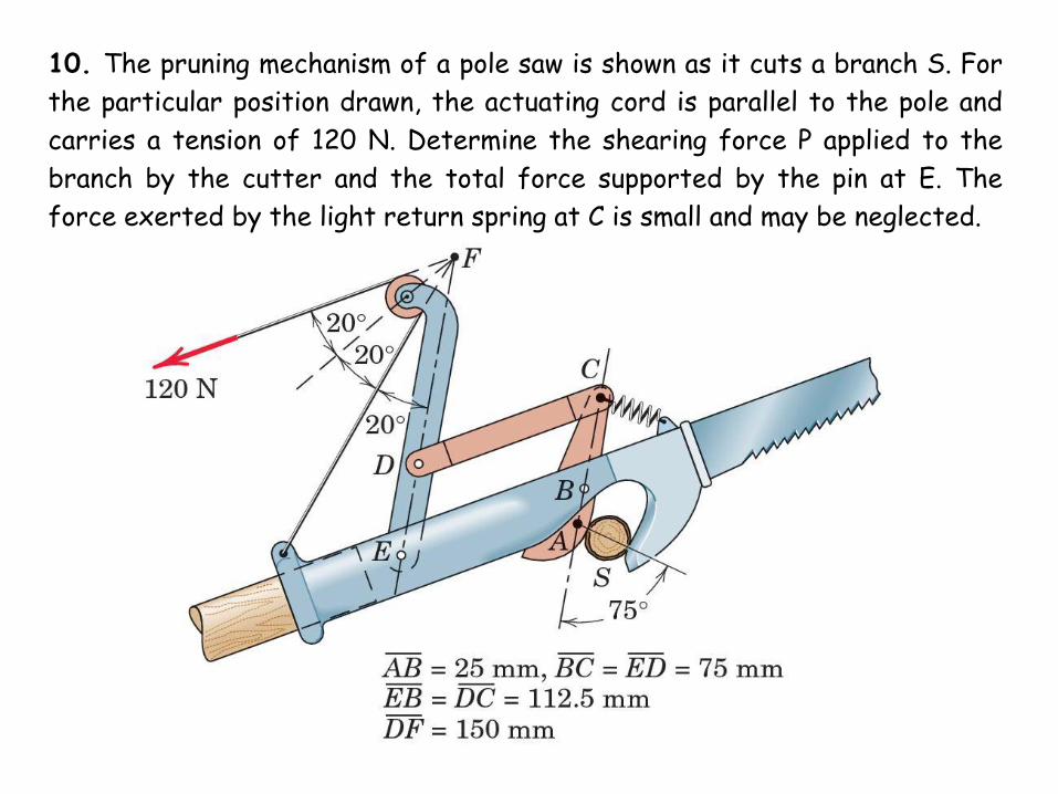
10. The pruning mechanism of a pole saw is shown as it cuts a branch S. For
the particular position drawn, the actuating cord is parallel to the pole and
carries a tension of 120 N. Determine the shearing force P applied to the
branch by the cutter and the total force supported by the pin at E. The
force exerted by the light return spring at C is small and may be neglected.

actuating cord is parallel to the pole and carries a tension of 120 N. Determine the shearing force P applied to the branch by the cutter and the total force supported by the pin at E. The force exerted by the light return spring at C is small and may be neglected.
FDE
DC two force member

actuating cord is parallel to the pole and carries a tension of 120 N. Determine the shearing force P applied to the branch by the cutter and the total force supported by the pin at E. The force exerted by the light return spring at C is small and may be neglected.
ABC

11. The figure shows a simplified sketch of the mechanism used to raise the bucket of a bulldozer. The bucket and its contents weigh 10 kN and have acenter of gravity at H. Arm ABCD has a weight of 2 kN and a center of gravity at B; arm DEFG has a weight of 1 kN and a center of gravity at E. The weight of the hydraulic cylinders can be ignored. Calculate the forces in the hydraulic cylinders and all forces acting on arm DEFG for the position shown.
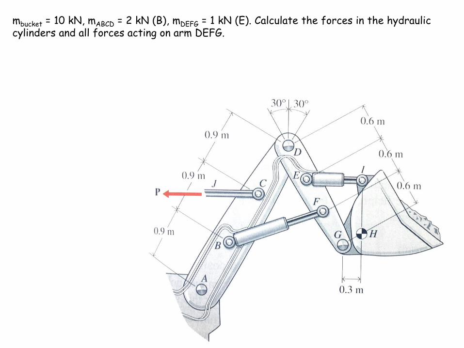
mbucket = 10 kN, mABCD = 2 kN (B), mDEFG = 1 kN (E). Calculate the forces in the hydraulic cylinders and all forces acting on arm DEFG.