sl-qc coder parts list and operating instructions coder parts list and operating instructions...
TRANSCRIPT

SL-QC CODER PARTS LIST AND
OPERATING INSTRUCTIONS
Marion, IL STK. NO. 5800-102

SL-QC CODER 1
CONTENTS Installation 2
Operating Instructions 2-3
Maintenance 3
Problems & Corrections 4
Instructions for Mounting New Die Wheel & Die Wheel Shaft & Rotor Assembly 5-6
To Change From Left to Right Conveyor Mounting 7-8
Repair Parts List, SL-QC Coders (Table 1) 9-10
Dust Cover & Arm Assembly (Table 2) 11
Model SL-QC Cartridges (Table 3) 12

SL-QC CODER 2
INSTALLATION
1. The SL-QC Coder should be mounted so that the object to be printed contacts the die wheel with about 1/4” interference (see figure 1).
NOTE: The SL-QC Coder is presently set for left-hand mounting (see figure 3A.)
2. The mounting bracket assembly should be attached flush to the parent machine so the die wheel is parallel to the surface to be printed. When there are obstacles to mounting the SL-QC Coder directly to the parent machine, secure the SL-QC Coder mounting bracket to a slotted angle iron and then attach to the parent machine.
3. Light cases or objects not printed in the compressing section of a case sealer may require a support guide opposite the die wheel to keep cases or objects from shifting during the imprinting operation.
OPERATING INSTRUCTIONS
1. Changing Type Holders—Turn the Ink Cartridge Cam to move the car-tridge away from the die wheel. Turn the type holder latch 90 degrees to release the type holder. Remove the type holder by lifting from the die wheel. When replacing the type holder, return type holder latch to locked position. IMPORTANT: Return ink cartridge to print position by turning Ink Cartridge Cam (#9).
2. Positioning Type Holder Latch—The type holder latch may be posi-tioned any place around the die wheel that is most convenient to the user. To reposition the type holder latch, loosen 3 screws. Move the latch to position desired and tighten screws. If multiple coders are used it may be helpful to set all the coders the same so the type hold-ers may be interchanged from one coder to another and hold correct print registration.
3. Flex Base Type Changes—the flex base type holders are designed to grip the type on the ends when it is pressed into them. Pull old type out and install new type by starting one end into type holder and pressing firmly in and down on the other end until type is solid against bottom of type holder.
SL-QC CODER 3
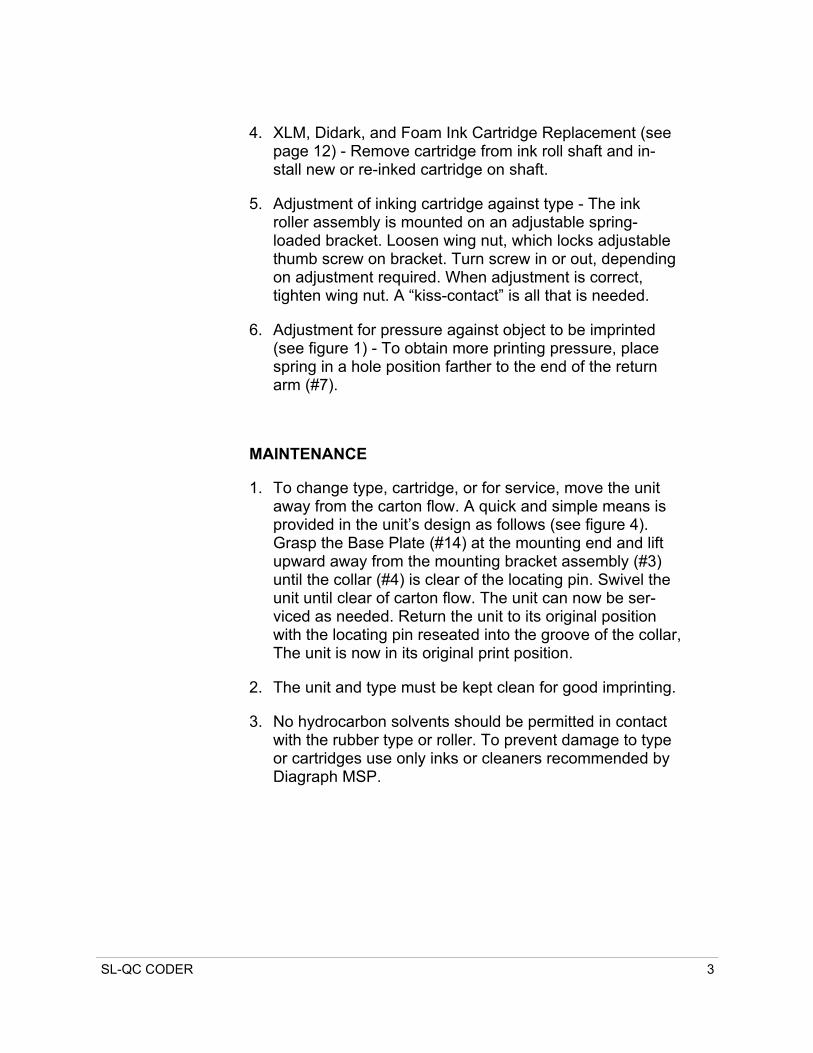
4. XLM, Didark, and Foam Ink Cartridge Replacement (see page 12) - Remove cartridge from ink roll shaft and in-stall new or re-inked cartridge on shaft.
5. Adjustment of inking cartridge against type - The ink roller assembly is mounted on an adjustable spring-loaded bracket. Loosen wing nut, which locks adjustable thumb screw on bracket. Turn screw in or out, depending on adjustment required. When adjustment is correct, tighten wing nut. A “kiss-contact” is all that is needed.
6. Adjustment for pressure against object to be imprinted (see figure 1) - To obtain more printing pressure, place spring in a hole position farther to the end of the return arm (#7).
MAINTENANCE
1. To change type, cartridge, or for service, move the unit away from the carton flow. A quick and simple means is provided in the unit’s design as follows (see figure 4). Grasp the Base Plate (#14) at the mounting end and lift upward away from the mounting bracket assembly (#3) until the collar (#4) is clear of the locating pin. Swivel the unit until clear of carton flow. The unit can now be ser-viced as needed. Return the unit to its original position with the locating pin reseated into the groove of the collar, The unit is now in its original print position.
2. The unit and type must be kept clean for good imprinting.
3. No hydrocarbon solvents should be permitted in contact with the rubber type or roller. To prevent damage to type or cartridges use only inks or cleaners recommended by Diagraph MSP.
SL-QC CODER 4
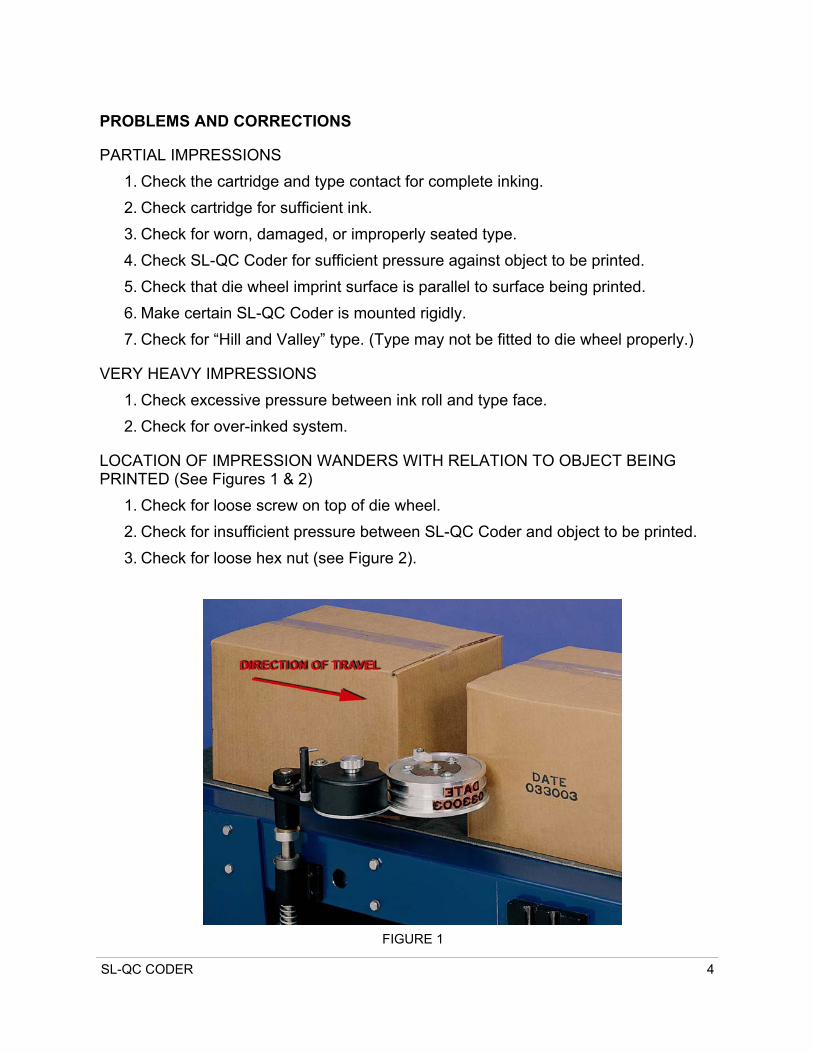
PROBLEMS AND CORRECTIONS
PARTIAL IMPRESSIONS 1. Check the cartridge and type contact for complete inking. 2. Check cartridge for sufficient ink. 3. Check for worn, damaged, or improperly seated type. 4. Check SL-QC Coder for sufficient pressure against object to be printed. 5. Check that die wheel imprint surface is parallel to surface being printed. 6. Make certain SL-QC Coder is mounted rigidly. 7. Check for “Hill and Valley” type. (Type may not be fitted to die wheel properly.)
VERY HEAVY IMPRESSIONS 1. Check excessive pressure between ink roll and type face. 2. Check for over-inked system.
LOCATION OF IMPRESSION WANDERS WITH RELATION TO OBJECT BEING PRINTED (See Figures 1 & 2)
1. Check for loose screw on top of die wheel. 2. Check for insufficient pressure between SL-QC Coder and object to be printed. 3. Check for loose hex nut (see Figure 2).
FIGURE 1
SL-QC CODER 5
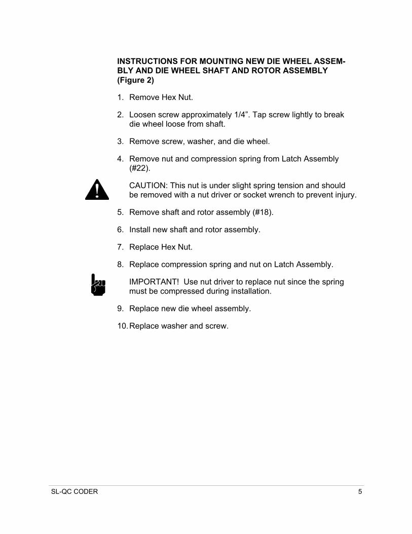
INSTRUCTIONS FOR MOUNTING NEW DIE WHEEL ASSEM-BLY AND DIE WHEEL SHAFT AND ROTOR ASSEMBLY (Figure 2)
1. Remove Hex Nut.
2. Loosen screw approximately 1/4”. Tap screw lightly to break die wheel loose from shaft.
3. Remove screw, washer, and die wheel.
4. Remove nut and compression spring from Latch Assembly (#22).
CAUTION: This nut is under slight spring tension and should be removed with a nut driver or socket wrench to prevent injury.
5. Remove shaft and rotor assembly (#18).
6. Install new shaft and rotor assembly.
7. Replace Hex Nut.
8. Replace compression spring and nut on Latch Assembly.
IMPORTANT! Use nut driver to replace nut since the spring must be compressed during installation.
9. Replace new die wheel assembly.
10. Replace washer and screw.

SL-QC CODER 6
FOR ILLUSTRATION PUR-POSES ONLY. REFER TO FIGURE 4 FOR PARTS BREAKDOWN OF ITEMS REQUIRED.
FIGURE 2
Screw
Washer
Shaft and Rotor Assembly
Hex Nut

SL-QC CODER 7
FIGURE 3A LEFT HAND (STANDARD FACTORY SET)
INK ROLLER ASSEMBLY
DIE WHEEL ASS’Y
22 21
8
7
9
SL-QC CODER 8
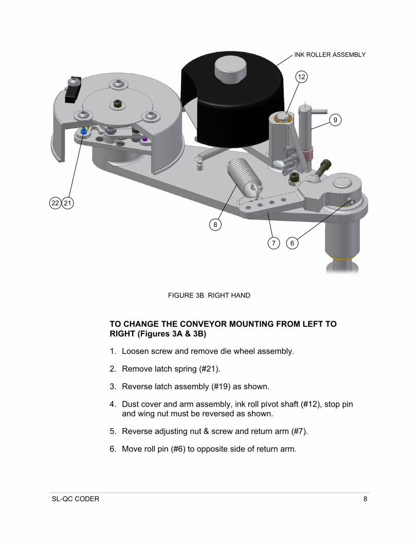
TO CHANGE THE CONVEYOR MOUNTING FROM LEFT TO RIGHT (Figures 3A & 3B)
1. Loosen screw and remove die wheel assembly.
2. Remove latch spring (#21).
3. Reverse latch assembly (#19) as shown.
4. Dust cover and arm assembly, ink roll pivot shaft (#12), stop pin and wing nut must be reversed as shown.
5. Reverse adjusting nut & screw and return arm (#7).
6. Move roll pin (#6) to opposite side of return arm.
FIGURE 3B RIGHT HAND
22 21
8
7 6
9
12
INK ROLLER ASSEMBLY
SL-QC CODER 9
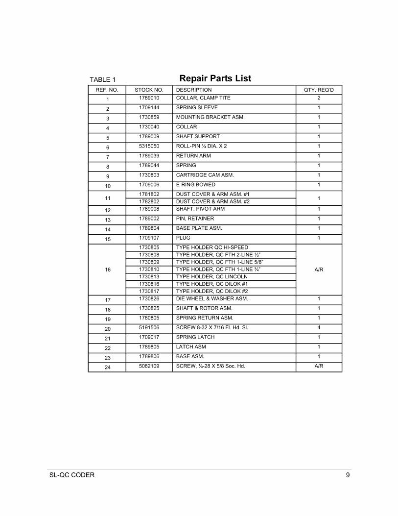
TABLE 1 Repair Parts List REF. NO. STOCK NO. DESCRIPTION QTY. REQ’D
1 1789010 COLLAR, CLAMP TITE 2
2 1709144 SPRING SLEEVE 1
3 1730859 MOUNTING BRACKET ASM. 1
4 1730040 COLLAR 1
5 1789009 SHAFT SUPPORT 1
6 5315050 ROLL-PIN ¼ DIA. X 2 1
7 1789039 RETURN ARM 1
8 1789044 SPRING 1
9 1730803 CARTRIDGE CAM ASM. 1
10 1709006 E-RING BOWED 1
11 1781802 DUST COVER & ARM ASM. #1
1 1782802 DUST COVER & ARM ASM. #2
12 1789008 SHAFT, PIVOT ARM 1
13 1789002 PIN, RETAINER 1
14 1789804 BASE PLATE ASM. 1
15 1709107 PLUG 1
16
1730805 TYPE HOLDER QC HI-SPEED
A/R
1730808 TYPE HOLDER, QC FTH 2-LINE ½” 1730809 TYPE HOLDER, QC FTH 1-LINE 5/8” 1730810 TYPE HOLDER, QC FTH 1-LINE ¾” 1730813 TYPE HOLDER, QC LINCOLN 1730816 TYPE HOLDER, QC DILOK #1 1730817 TYPE HOLDER, QC DILOK #2
17 1730826 DIE WHEEL & WASHER ASM. 1
18 1730825 SHAFT & ROTOR ASM. 1
19 1780805 SPRING RETURN ASM. 1
20 5191506 SCREW 8-32 X 7/16 Fl. Hd. Sl. 4
21 1709017 SPRING LATCH 1
22 1789805 LATCH ASM 1
23 1789806 BASE ASM. 1
24 5082109 SCREW, ¼-28 X 5/8 Soc. Hd. A/R

SL-QC CODER 10
FIGURE 4
1
5
4
3
2
1
7
14
6
19
9
10
16
17
15
20
23
21
22
11
18
12
13
8

SL-QC CODER 11
FIGURE 5
TABLE 2
DUST COVER & ARM ASSEMBLY
REF. NO. STOCK NO. DESCRIPTION NO. REQ’D. 70 1789-005 Spring 1 71 1789-062 Knob 1
72 1781-002 Dust Cover #1
1 1781-103 Dust Cover #2 1781-004 Dust Cover #3
72
71
70
SL-QC CODER 12
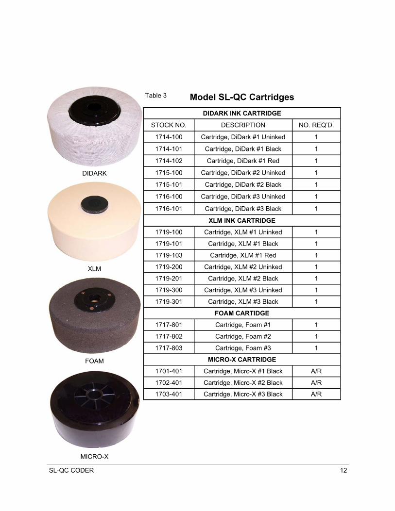
DIDARK INK CARTRIDGE
STOCK NO. DESCRIPTION NO. REQ’D.
1714-100 Cartridge, DiDark #1 Uninked 1
1714-101 Cartridge, DiDark #1 Black 1
1714-102 Cartridge, DiDark #1 Red 1
1715-100 Cartridge, DiDark #2 Uninked 1
1715-101 Cartridge, DiDark #2 Black 1
1716-100 Cartridge, DiDark #3 Uninked 1
1716-101 Cartridge, DiDark #3 Black 1
XLM INK CARTRIDGE
1719-100 Cartridge, XLM #1 Uninked 1
1719-101 Cartridge, XLM #1 Black 1
1719-103 Cartridge, XLM #1 Red 1
1719-200 Cartridge, XLM #2 Uninked 1
1719-201 Cartridge, XLM #2 Black 1
1719-300 Cartridge, XLM #3 Uninked 1
1719-301 Cartridge, XLM #3 Black 1
FOAM CARTIDGE
1717-801 Cartridge, Foam #1 1
1717-802 Cartridge, Foam #2 1
1717-803 Cartridge, Foam #3 1
MICRO-X CARTRIDGE
1701-401 Cartridge, Micro-X #1 Black A/R
1702-401 Cartridge, Micro-X #2 Black A/R
1703-401 Cartridge, Micro-X #3 Black A/R
Table 3 Model SL-QC Cartridges
DIDARK
XLM
FOAM
MICRO-X