sketch-based interaction a sketch-based interface for...
TRANSCRIPT
Sketch-Based Interaction
72 January/February 2007 Published by the IEEE Computer Society 0272-1716/07/$20.00 © 2007 IEEE
D espite sometimes questionable userfriendliness, software solutions for 2D
image authoring and editing are now a widespreadcommodity among average computer users. Clearly, thesame cannot be said of 3D suites; the introduction of athird dimension on intrinsically 2D input and outputdevices—the mouse and screen—adds a discouragingcomplexity that only professional artists and a fewskilled amateurs can overcome.
To make such tools appealing to a broader audience,researchers have devoted considerable effort to enhanc-
ing ease of use and creating intuitiveinterfaces based on simple, well-understood tasks. To convey 3Dshapes, people typically sketchthem—or, more precisely, sketch a2D projection of the shape fromwhich our brains can seamlesslyreconstruct a full 3D representation.Sketch-based interfaces seem all themore convenient because most peo-ple who design 3D objects and reg-ularly use 3D modeling programsalready use sketches and artworkextensively in early phases of the
creative process. As Figure 1 shows, this is especiallytrue of fashion designers when they create new gar-ments.
In fashion design, the required step between the ini-tial concept art and the final product is currently cum-bersome and requires know-how possessed only bytrained designers (see the “Feedback from a FashionDesigner” sidebar for further discussion on what thisentails). Fashion design’s final product might be a realgarment or virtual clothes for virtual actors or videogame characters, which we focus on here. To clothe suchcharacters, designers use a range of approaches. Forincidental characters, the clothing might be no morethan a texture map. For lead characters in feature films,they might use full-fledged physical simulation ofdetailed cloth models. In between, designers often usesimple skinning techniques (that is, a garment isdeformed by a skeleton), combined with texture map-
ping to create clothing that deforms somewhat as thecharacter moves.
Our goal is to make it easy for users to generate sim-ple garments adapted to existing models. We believethat for most people, drawing garments worn by a man-nequin—which is how they imagine them—is easierthan the traditional pipeline in which they create the2D patterns needed to sew garments. We thereforedeveloped a sketch-based interface that lets users quick-ly construct 3D virtual garments on a character model.Our system offers simple yet effective solutions to shapegeneration and placement, and basic clothing simula-tion in a resting position. The system is also easy to use:our contributing designer created the entire wardrobefeatured in this article in less than an hour.
Designing for virtual charactersClothing virtual characters entails three problems:
designing the clothes (tailoring), placing them on thecharacter (dressing), and making them look physicallycorrect (simulating).
Existing methodsIn the tailoring process for human beings, the design-
er must choose the cloth, fit it to the body, adjust thegarment’s pattern pieces to fit the model, and sew thepieces into a garment. A virtual character’s garment typ-ically has no patterns with which to sew, and is insteadrepresented by a simple polygon mesh that designersconstruct to fit the body. Currently, constructing suchmeshes is tedious, even without patterns and stitching.Designers sometimes construct the garment by directlyincorporating the cloth mesh into a character’s geomet-ric model so that the character has pants but no legs, forexample. In this case, physical simulation is impossible,so when a character needs new clothes, designers mustlargely remodel it.
As an alternative, designers can draw pattern piecesfor a garment and position them over the character’snaked form, defining stitching constraints and so on. Thiscan be wearisome, however, especially when the charac-ter is relatively unimportant. This approach also requiresthat designers understand how cloth fits over forms,
This interactive system forgarment creation determines agarment’s shape and how thecharacter wears it based on auser-drawn sketch. The systemthen uses distances betweenthe 2D garment silhouette andthe character model to inferremaining distance variations in 3D.
Emmanuel Turquin, Jamie Wither, Laurence Boissieux, and Marie-Paule CaniGrenoble University
John F. HughesBrown University
A Sketch-BasedInterface forClothing VirtualCharacters
although the actual pattern-and-stitching informationmight be irrelevant once tailoring is completed. (In rarecases, the cloth’s physical properties—such as whether itwas cut on the bias or it resists folding along one axis—might be relevant to a full-fledged physical simulation.)To ease the process, we draw inspiration from previouswork on sketch-based interfaces (see the “Related Work”sidebar at the end of the article for more details).
A sketch-based approachOur approach combines tailoring, dressing, and phys-
ical plausibility into a single step to create a mesh that isboth visually pleasing and suitable for later complex sim-ulation or skinning approaches. We described a prelim-inary version of our system elsewhere;1 here, we presentthe system in detail and describe several new aspects,including
■ generation of complete (back and front) garments,■ fold-sketching,■ graphical user interface improvements, and■ feedback from a seasoned fashion designer.
Our system’s two key features are its pleasant user-interaction experience and its method for reconstruct-ing the garment’s 3D geometry and placement from a2D sketch. As in work by Bourguignon and colleagues,2
our system lets users sketch garments directly on a 3Dvirtual actor body model. However, our method outputsa full 3D geometry for the garment, using the distancefrom the 2D garment silhouette to the body model toinfer distance variations between the garment and thecharacter in 3D.
The system performs this reconstruction in four steps.First, it automatically classifies the 2D garment draw-ing’s contour lines as either silhouettes (lines that don’t
cross the body) or borderlines (lines that cross thebody). Next, it computes a distance-to-the-body valuefor each point of a silhouette segment and uses thesedistances to determine desired point-to-body distancesfor the borderlines. It then propagates this distanceinformation in 2D to find desired point-to-body dis-tances, which it uses to determine the garment’s 3Dposition. When the drawing includes fold strokes indi-cating fold location and placement, the system adjuststhe garment’s distance values so that the establishedlevel moves closer to or farther from the body.
IEEE Computer Graphics and Applications 73
Feedback from a Fashion DesignerFashion designer Laurence Boissieux has experience in
creating both real and virtual garments. She produced thesketch in Figure 1 and most garments featured in this article.Boissieux offers the following commentary on the system.
For a designer, the most natural way to create newfashion is with a simple sheet of paper and a good oldpencil. But designers must keep up with the times and enterthe digital age. So far, the existing tools for creating clothesin most 3D modeling systems are based on a quite complexsequence of steps. The first is to draw flat panels, whichpresupposes a strong knowledge of pattern making. Noteveryone has such skills; in the fashion industry, patternmaking is a distinct job and is not typically handled by thedesigners themselves. Once the panels are created, usersmust arrange them correctly in space around the body. Thenext step is to specify seams, and finally to launch a physicalsimulation that will pull the different panels toward eachother. Assuming users choose all parameters well, given alot of trials—and time!—they’ll get a 3D garment.
The real strength of the sketch-based interface is—as thename claims—that it’s true to the designer’s natural
gestures. It replaces paper and pencil with a graphic tablet,which is strictly equivalent. And, above all, designers areonly expected to draw—something they’re used to doing.The system bears a likeness to reality in its use of metaphors:to remove a line, you just scribble on it. Users can draw andredraw strokes until they’re satisfying. Generating the 3Dshape is as simple as clicking a button, and the computationis efficient and quick. The result is nearly instantaneous—noneed to wait for endless iterations.
This speed lets designers go back and forth from thesketch to the garment, making rapid changes. The samedrawing metaphor lets the designer add folds. Although thefold shapes are somewhat automatic, they’re aligned onfree-hand curves and thus look natural. This is another greatfeature that painlessly enriches the models and gives themmore realism at no cost. Another interesting aspect is thateven neophytes can play designer: the system doesn’trequire any particular know-how. It’s easy to get into it andvery intuitive. My wish as designer would be to see thissystem included in well-known 3D modelers so thatdevelopers could create nicely shaped garments quickly,easily, and directly—and then have more time to focus onanimation!
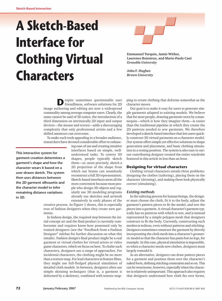
1 A sketched-based approach to 3D cloth modeling. (a) Our designercreated a traditional fashion design sketch early in the design process toconvey her vision on paper. (b) She then reproduced the design using oursketch-based interface. (c) The resulting system-generated 3D garment.
(a) (b) (c)
The sketch-based interfaceA central objective of any sketch-based interface is to
give users the benefits of a traditional pencil-and-draw-ing-board, while providing as much new functionalityas possible. To achieve this, we seek to minimize mod-ifier keys and buttons, and UI modes (such as CapsLock). Our system uses only one button (which letsusers employ devices such as graphical tablets or tabletPCs), a few mode sets, and an optional symmetry mode.
The first mode set lets users toggle between con-tour mode (sketching the garment’s contours) andfolding mode (sketching the garment’s folds). Con-tour mode is the default, and is the starting point forany garment creation. Folding mode is subsidiary. Inthe second mode set, users choose between applyingstrokes to the garment’s front, back, or both (thedefault behavior). Finally, an optional symmetry
mode helps users draw vertically sym-metrical garments.
Although we believe our interface pro-vides an intuitive way of designing gar-ments, the major contribution of ourapproach is in the method for gener-ating a 3D garment from a finished 2Dsketch. The sketching phase in itself clear-ly leaves room for improvement; we couldpush the drawing-board metaphor furtherby introducing techniques such as cluster-ing and beautification of fuzzy strokes, oroversketching as a way of editing the current sketch.3
Typical user interactionTo illustrate the system’s performance,
we describe a typical interaction in whicha user, Edna, sketches a skirt on a femalemodel.
Contour mode. As Figure 2a shows,Edna first draws a line across the model’swaist (indicating the top of the skirt), thendraws a line down the side (indicating theskirt’s silhouette). Next, she draws a lineacross the bottom in a V shape to indicatethat the skirt’s front should dip down. Shefinishes with the other side. The systemthen applies a simple corner-detectionprocess—based on the 2D curvature’s vari-ation—to break the sketch into parts. Thesystem accidentally detects one extra cor-ner (at the bottom of the V shape), whichEdna deletes using a deletion gesture. Shecould also add new breakpoints, but noneare necessary here. (As we describe later,breakpoints determine the garment’s glob-al 3D position with respect to the body, andthus play an important role in the 3D posi-tioning process.) As Figure 2b shows, thesystem classifies the two side lines as sil-houettes, and the other lines as borderlines.
Edna now presses a button to see the gar-ment that the system has inferred (see Fig-
ure 2c); almost instantly, the system displays a surfacethat matches the drawn constraints, but adapts to theunderlying form’s shape (see the waistline, for example).Sometimes, the system’s breakpoint-inference fails todetect all the points the user wants; in this case, she canmake a gesture (see Figure 3) to add new breakpoints.
Folding mode. Now that Edna is satisfied with theskirt’s global shape, she decides to add a few folds toobtain a more physically plausible 3D surface. To do this,she simply switches to folding mode and draws strokesthat mark the presence of either ridges or valleys. Shecan also specify the folds’ width and amplitude in anintuitive way (see Figure 4).
Front/back modes. By default, the user’s strokesaffect both the garment’s front and back parts. Typically,
Sketch-Based Interaction
74 January/February 2007
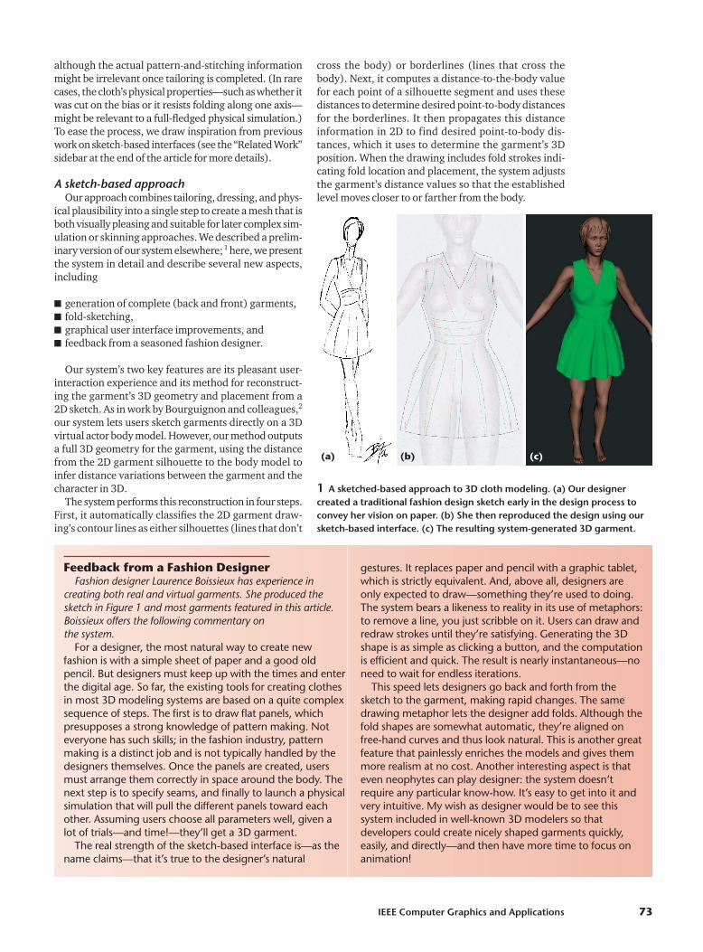
2 Example user interaction. (a) After the user draws a few lines in contour mode toindicate the skirt’s shape, the system’s corner-detector detects a breakpoint that the userdoesn’t want. The user therefore deletes the breakpoint by drawing a circle around it.(b) The system classifies the remaining lines and displays silhouette lines in red andborders in yellow. (c) The user requests a reconstruction, and the system displays theinferred surface.
(a) (b) (c)
3 Adding new breakpoints. The user had outlined a skirt in contour mode without sharpcorners at the bottom, so the system’s corner-detector failed to insert breakpoints. (a)The user draws short strokes (in green) that cross the contour to indicate the need fornew breakpoints. (b) The system inserts the new breakpoints. (c) The reconstructed skirt.
(a) (b) (c)
4 Folding mode. (a) The user draws a few fold lines (thick green lines) that correspondto ridges or valleys on the garment’s surface. (b) The width of the u-shaped gesturecrossing each end of a fold line determines the fold’s width; its depth determines thefold’s depth. The system indicates both width and depth using a pink-circled Gaussianprofile at the end of each fold line. (c) The system adds the folds to the skirt.
(a) (b) (c)
the two views share most lines. This is always true for sil-houettes, which by definition join the front and back parts;it’s often true of borders as well. However, our system alsolets users edit front and back borders independently by tog-gling to the appropriate mode—so long as the contourremains closed (see Figure 5). To avoid confusion, whenborders differ, the system renders the borders belongingto the current view with a continuous stroke, while othersappear dashed. There is no constraint on how users editthe folds, but it’s usually best to generate different foldingfor the front and back parts.
Vertical symmetry. Garments often exhibit verti-cal (that is, left to right) symmetry. Consequently, thesystem has a mirror mode in which only half the canvasis active; the other half automatically reproduces mir-rored versions of the strokes. When a stroke crosses thesymmetry axis, the system cuts it at the intersection andjoins the left and right parts. Users can deactivate thesymmetry mode by pressing a key.
Gestural interface componentsThe system interprets the user’s marks as gestures;
in contour mode, it defaults to silhouette and border-line segment construction. As Figure 6 shows, other gestures add classification-process breakpoints, deletebreakpoints, delete a segment or segment chain, andclear all segments.
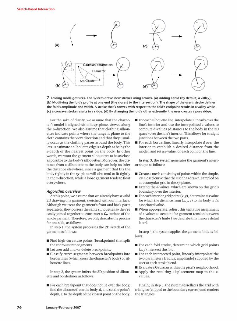
The folding mode default gesture creates a new fold-ing line. Stroke deletion gestures are valid, but becausebreakpoints are irrelevant in this mode, the systemreplaces corresponding gestures with other gestures tocontrol fold profiles (see Figure 7 on the next page).
The breakpoint-deletion gesture is similar to the stan-dard proofreader’s deletion mark; other deletion ges-tures require multiple intersections with existing strokesto prevent accidental deletions.
Interpreting garment sketchesReconstructing a 3D surface from a 2D drawing is
clearly an underconstrained problem; however, by con-sidering clothing’s special nature we can generate aplausible guess of the user’s intentions.
First, we want to find a model position and a 2D pro-jection such that for every P(xp, yp) of the image plane,the back-projected 3D ray possesses at most two inter-sections with the model’s body surface, becausethen this property also holds for most one-layer gar-ments. In other words, we need a pose that minimizessurface overlappings (or maximizes the visible surface),and lets us represent the garment with two heightfields—one for the front and another for the back. Tosatisfy this constraint, we chose a standing stance withspread-eagled arms that’s viewable from the front orback. In this pose, the only body parts that don’t com-ply with the desired property are the extremities (head,hands, feet), which aren’t usually covered by cloth. Sec-ond, users should be able to construct the front and backparts with two different viewpoints so they can edit thecurrently visible part. Because we want the two viewsto share the same silhouette lines, we must use an ortho-graphic projection.
z zpf
pb,
IEEE Computer Graphics and Applications 75
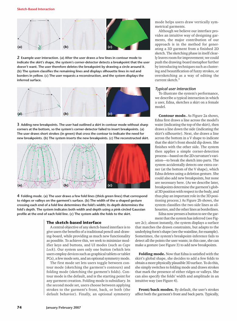
5 Using frontand backmodes. (a)When the gar-ment’s front isdisplayed infront mode, thefolds in the backare rendered indashed ratherthan solid lines.(b) The result-ing garmentfront. (c) Thegarment back inback mode. (d)The result.
(c) (d)
(a) (b)
(a)
(b)
(c)
(d)
(e)
(f)
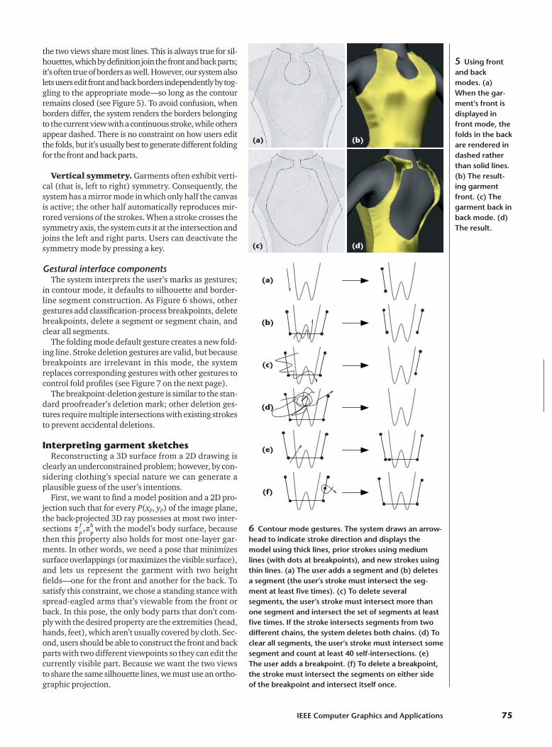
6 Contour mode gestures. The system draws an arrow-head to indicate stroke direction and displays themodel using thick lines, prior strokes using mediumlines (with dots at breakpoints), and new strokes usingthin lines. (a) The user adds a segment and (b) deletesa segment (the user’s stroke must intersect the seg-ment at least five times). (c) To delete severalsegments, the user’s stroke must intersect more thanone segment and intersect the set of segments at leastfive times. If the stroke intersects segments from twodifferent chains, the system deletes both chains. (d) Toclear all segments, the user’s stroke must intersect somesegment and count at least 40 self-intersections. (e)The user adds a breakpoint. (f) To delete a breakpoint,the stroke must intersect the segments on either side of the breakpoint and intersect itself once.(a) (
For the sake of clarity, we assume that the charac-ter’s model is aligned with the xy-plane, viewed alongthe z–direction. We also assume that clothing silhou-ettes indicate points where the tangent plane to thecloth contains the view direction and that they usual-ly occur as the clothing passes around the body. Thislets us estimate a silhouette edge’s z-depth as being thez-depth of the nearest point on the body. In otherwords, we want the garment silhouettes to be as closeas possible to the body’s silhouettes. Moreover, the dis-tance from a silhouette to the body can help us inferthe distance elsewhere, since a garment that fits thebody tightly in the xy-plane will also tend to fit tightlyin the z-direction, while a loose garment tends to floateverywhere.
Algorithm overviewAt this point, we assume that we already have a valid
2D drawing of a garment, sketched with our interface.Although we treat the garment’s front and back partsseparately, they possess the same silhouettes so they’reeasily joined together to construct a C0 surface of thewhole garment. Therefore, we only describe the processfor one side, as follows.
In step 1, the system processes the 2D sketch of thegarment as follows:
■ Find high-curvature points (breakpoints) that splitthe contours into segments.
■ Let user add and/or delete breakpoints.■ Classify curve segments between breakpoints into
borderlines (which cross the character’s body) or sil-houette lines.
In step 2, the system infers the 3D position of silhou-ette and borderlines as follows:
■ For each breakpoint that does not lie over the body,find the distance from the body, d, and set the point’sdepth, z, to the depth of the closest point on the body.
■ For each silhouette line, interpolate z linearly over theline’s interior and use the interpolated z values tocompute d-values (distances to the body in the 3Dspace) over the line’s interior. This allows for straightjunctions between the two parts.
■ For each borderline, linearly interpolate d over theinterior to establish a desired distance from themodel, and set a z-value for each point on the line.
In step 3, the system generates the garment’s interi-or shape as follows:
■ Create a mesh consisting of points within the simple,2D closed curve that the user has drawn, sampled ona rectangular grid in the xy-plane.
■ Extend the d-values, which are known on this grid’sboundary, over the interior.
■ For each interior grid point (x ,y), determine z’s valuefor which the distance from (x, y, z) to the body is d’sassociated value.
■ When appropriate, adjust this tentative assignmentof z-values to account for garment tension betweenthe character’s limbs (we describe this in more detaillater).
In step 4, the system applies the garment folds as fol-lows:
■ For each fold stroke, determine which grid points (x, y) intersect the fold.
■ For each intersected point, linearly interpolate thetwo parameters (radius, amplitude) supplied by theuser at each stroke’s end.
■ Evaluate a Gaussian within the pixel’s neighborhood.■ Apply the resulting displacement map to the z-
values.
Finally, in step 5, the system tessellates the grid withtriangles (clipped to the boundary curves) and rendersthe triangles.
Sketch-Based Interaction
76 January/February 2007
Gaussian parameters
Amplitude
Diameter
(a)
(b)
(c)
(d)
7 Folding mode gestures. The system draws new strokes using arrows. (a) Adding a fold (by default, a valley). (b) Modifying the fold’s profile at one end (the closest to the intersection). The shape of the user’s stroke definesthe fold’s amplitude and width. A stroke that’s convex with respect to the fold’s endpoint results in a valley while(c) a concave stroke results in a ridge. (d) By changing the fold’s other extremity, the user creates a pure ridge.
Precomputing a distance fieldTo accelerate algorithm steps 2 and 3, we precompute
a distance field to the character’s model when the modelis loaded. That is, for each point of a 3D grid around themodel, we use an octree-based algorithm to determineand store the distance to the model’s nearest point. Wediscretize the distance field on a regular grid. We coulduse more advanced techniques—such as adaptive struc-tures—to both represent and compute the distance field.However, this computation is a preprocessing step andperformance is not crucial; moreover, accessing a regu-lar grid during runtime is fast enough.
The system uses the distance field each time it needsto find the z-coordinate to assign to a point p(x0, y0) tomake it lie at a given distance from the model. It easilyaccomplishes this by stepping along the ray R(z) �(x0, y0, z) and stopping when it reaches the adequatedistance value (we interpolate trilinearly to estimate dis-tances for nongrid points). When the system performsthis computation during a sweeping procedure, it startsthe stepping at a neighboring pixel’s existing z-value,which ensures efficiency and the result’s spatial coher-ence. Otherwise, it starts the process near the near planeof the rectangular frustum on which the distance fieldhas been computed.
Results quality and computation time depends direct-ly on the resolution of the 3D grid storing the distancefield. The size of the 3D grid is user configurable, but wegenerally use a 128 � 128 � 128 grid to cover the wholebody.
Processing contour linesTo generate the garment’s 3D surface, the system
must analyze the user’s 2D strokes and assign them a3D position.
2D processingFirst, the system must classify the parts of the user’s
sketch. When the user starts or ends a new line with-in a few pixels of an existing line’s endpoint, the sys-tem assumes that the lines connect. While the user isdrawing, the system breaks finished lines into seg-ments by detecting points of high 2D curvature (break-points).
Once the sketch is complete—that is, it forms a sim-ple, closed curve in the plane—the system further clas-sifies all segments. It classifies a segment as a borderlineif the segment’s projection meets the body’s projectionin the xy-plane; otherwise, it classifies it as a silhouette.To make such classification efficient, we precompute thebody’s projection mask and store it in a buffer (the bodymask). Users can see the resulting segmentation, andcan add or delete breakpoints indicating segmentboundaries as necessary. Following this, the systemreclassifies the segments.
Distance and z-value at breakpointsWe use the body mask to find breakpoints that are
located over the body model; these points indicate gar-ment regions that fit tightly to the body. We assign suchpoints a zero distance from the model, setting their z-value to the body’s z at this specific (x, y) location.
To assign a distance value d to a breakpoint that does-n’t lie over the body, the system:
■ steps along the ray from the eye in the direction of thebreakpoint’s projection into the xy-plane,
■ checks distance values in the distance field data struc-ture as it goes, and
■ finds the z-value that minimizes this distance.
By assigning the breakpoint the discovered z- and d-val-ues, we position the breakpoint in 3D.
Line positioning in 3DWe use the breakpoints’ computed 3D positions to
roughly position the garment in 3D, inferring the gar-ment’s shape primarily from distances to the body alongthe sketch silhouettes. To position the silhouette linesin 3D, we interpolate z linearly along the edge betweenthe two breakpoints at the silhouette’s extremities. Wethen set the d-values for interior silhouette points tothose stored in the precomputed distance field. Instead,we could interpolate d directly, and compute associatedz-values. However, if the body curves away from the sil-houette curve, the interpolated d-value might have no z-value. Alternatively, we could compute d directly foreach interior point, then assign the closest body point’sz-value (as with breakpoints). In practice, however, thisleads to wiggly lines because of the coarse grid on whichwe precompute the approximate distance-to-body field.
So, having established the z- and d-values along sil-houette edges, we must extend this assignment to theborderlines. We do this in the simplest possible way: weassign d linearly along each borderline. Thus, for exam-ple, in Figures 2, 3, and 4, the d values at each end of thewaistline are small, so the entire waistline’s d-value willbe small. Likewise, the d-values for the hemline’s endsare quite large, so the values along the rest of the hem-line will be large, too.
3D reconstruction of the garment’ssurface
To infer the garment’s surface position, we use infor-mation gathered on the strokes.
Using distance to guess surface positionAs with the contour lines, our main clue for inferring
the garment interior’s 3D position is the interpolationof distances to the body. Propagating distance valuesinside the garment consists of several steps.
First, we use the closed 2D contour lines to generatean (x,y) buffer (sized to the sketch’s bounding box). AsFigure 8 (on the next page) shows, we assign each pixelin the buffer a value—in, out, or border—based on itsposition with respect to the contour. In a border pixel, acontour line intersects a small vertical or horizontal linein the pixel’s center. Other pixels are either inside or out-side the contour, depending on the contour’s windingnumber at the pixel center. We assign the border pixelsthe distance values already computed along the silhou-ette and borderlines.
We also want to minimize the distance variationinside the garment, so that the resulting garment is as
IEEE Computer Graphics and Applications 77
tight as possible, given the border constraints. Let � bethe set of inside and boundary pixels and �� the bound-ary. We already know the predetermined distancevalues on the boundary, and want to find an interpolantfd without extrema over �. This interpolant satisfies
(1)
Equation 1 is a Laplace equation with Dirichlet bound-ary conditions, which we can solve by simply iterating
convolutions with a 3 � 3 neighbors averaging mask over�. We then sweep in the 2D grid for computing z-val-ues at the inner pixels, corresponding to the distancesobtained with Equation 1.
Mimicking cloth tensionThe previous computation gives us a first guess of the
garment’s 3D position, but still results in artifactsbetween two limbs of the character. Due to tension inthe cloth itself, a garment should not fit tightly in theregion between two limbs (as in Figure 9a), but rathersmoothly interpolate the limbs’ largest z values. Toachieve this, we first erode the 2D body mask by a pro-portion that increases with the underlying d-value (seeFigure 9b, left). We then use a series of Bezier curves inhorizontal planes to interpolate the z-values for the in-between pixels. We chose horizontal gaps because of thehuman body’s structure: for an upright human (or mostother mammals), gaps between portions of the body aremore likely to be bounded by body on the left and rightthan to be bounded above and below.
To maintain garment surface smoothness near therecomputed region, we extract distance values from thenew z-values and the distance field. We perform somedistance propagation iterations again in 2D before recom-puting the z-values in the regions not lying over the body;these regions were not previously filled with the Beziercurves (as in the right side of Figures 9a and 9b).
Finally, we apply a smoothing step to the z-values toget a smoother shape for cloth that floats far from thecharacter’s model. To do this, we compute a smoothedversion of the z-buffer by applying a standard smoothingfilter. We then take a weighted average, at each pixel, ofthe old and smoothed z-values, with weighting coeffi-
cients depending on each pixel’s distancefrom the model.
Adding surface folds We express folds as a garment’s surface
deformation, where the deformation’smagnitude in z is at a maximum on the foldstroke, and decreases away from the stroke.The deformation’s magnitude correspondsto a 2D Gaussian centered on the strokepoint closest to the surface sample point.The algorithm proceeds as follows.
For each segment in the fold stroke,determine which pixels in the garmentmap intersect the segment. For each pixelintersected:
■ Clip the segment to the pixel.■ Determine the segment’s center point
(the origin for sampling the pixel’s 2D Gaussian).
■ Sample the Gaussian within the pixel’s neighborhood (see Figure 10).
We want the effect of the Gaussian to fallto zero at the radius users specify. Because99.7 percent of the Gaussian’s support iswithin three standard deviations (�), we
Δ = =f f fd d d
0 over withΩ Ω Ω, *δ δ
fd*|δΩ
Sketch-Based Interaction
78 January/February 2007
B
B
B
B
BB
I
I
I
II
I
I
I
IIII
O O O O
OOOO
O O O
O
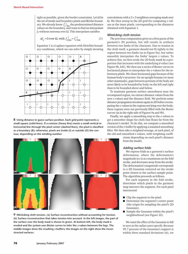
8 Using distance to guess surface position. Each grid point represents asmall square (solid lines). If a contour (heavy line) meets a small vertical orhorizontal line through the pixel center (dashed lines), the pixel is classifiedas a boundary (B); otherwise, pixels are inside (I) or outside (O) the con-tour, depending on the winding number.
9 Mimicking cloth tension. (a) Surface reconstruction without accounting for tension.(b) Surface reconstruction that takes tension into account. In the left images, the part ofthe surface over the body mask is shown in green. At bottom left, the body mask iseroded and the system uses Bézier curves to infer the z-values between the legs. Themiddle images show the resulting z-buffers; the images on the right show the recon-structed surfaces.
(b)
(a)
set the Gaussian’s � to be one-third of the radius. We lin-early interpolate the Gaussian’s radius and amplitudein each sampled pixel between the fold stroke’s extrem-ities. This interpolated radius specifies the size of thepixel’s neighborhood to sample.
Once we’ve computed all the folds’ contributions, weapply the resulting offset to the previously computed z-values.
Mesh generationIn the last step, we use the standard, diagonally sub-
divided mesh’s triangles as the basis for the mesh werender. We retain all inside vertices, remove all outsidevertices and triangles containing them, and moveboundary vertices to new locations using a simple rule:
■ If any segments end within the unit box around thevertex, we move the vertex to the average of those seg-ments’ endpoints. (Because segments tend to be long,it’s rare to have more than one endpoint in a box.)
■ Otherwise, some segments must intersect the box’svertical and/or horizontal midlines; we move the ver-tex to the average of all such intersections.
Essentially, we provide this simple triangulation to letusers instantly visualize the garments. To produce mesh-es suitable for simulation system use, for example, wecould replace this approach with a more elaboratemeshing scheme to generate more uniform meshes.
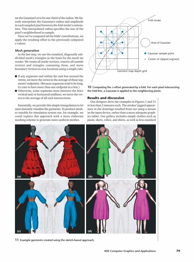
Results and discussionOur designer drew the examples in Figures 1 and 11
in less than 5 minutes each. The strokes’ jagged appear-ance in the drawings resulted from our using a mouseas the input device, rather than a more adequate graph-ics tablet. Our gallery includes simple clothes such aspants, skirts, robes, and shirts, as well as less-standard
IEEE Computer Graphics and Applications 79
10 Computing the z-offset generated by a fold. For each pixel intersectingthe fold line, a Gaussian is applied to the neighboring pixels.
+
+
+
+
+
+
+
+
Gaussian sample point
Center of clipped segment
Area of Gaussian
Fold stroke
Garment map depth grid
11 Example garments created using the sketch-based approach.
(a) (b)
(c) (d)
garments such as a bohemian dress and eccentric outfitssuitable for haute couture collections. This wide rangeof clothing types shows our system’s expressiveness.
We are aware that other approaches could be used forcloth design. For instance, someone could create a para-metric template for shirts and a program that lets usersplace the template over a particular character and thenadjust the shirt’s neckline, overall size, and so on. How-ever, this approach would limit design choices to a pre-defined template library and limit users to standardmodels as well. Nonetheless, such a model-basedapproach would be quite reasonable for many applica-tions, such as a virtual Barbie doll.
In addition to the approaches we described here, wecould use other methods or augmentations as well.First, our automated shape inference is simple and easyto understand, but might not be ideal in all cases. We’vealso yet to provide a way for users to edit the solutionto make it better match their sketched ideas. Second,our system currently generates only single-layer gar-ments. This is a reasonable limitation for dressingvideo-game characters, for example, but is certainlytoo restrictive for prototyping complex digital gar-
ments for movie characters—and even more so fordesigning real clothing.
Finally, our system can be a first step in a pipelinewhose final product is a more physically realistic gar-ment. Decaudin and colleagues, for example, have gen-erated 2D flat panels from an initial garment that oursystem produced.4 This, coupled with a fast physicalsimulation, could let users generate realistic garmentsthat closely match the input sketch.
Conclusion We plan to offer users more control over the generat-
ed surface’s geometric properties. Currently, we canonly ensure a C0 surface continuity, notably at the sil-houettes. A higher-order continuity might be desirablein many situations. To provide greater continuity, weplan to use an approximate (smoothed) distance fieldinstead of the Euclidean distance. This would also per-mit faster convergence of the iso-sets toward a sphere,which would result in smoother surfaces as users moveaway from the body. We might also replace the harmon-ic distance diffusion inside the garment with a more cus-tomizable one.
Sketch-Based Interaction
80 January/February 2007
Related WorkCurrent interactive systems1-3 for designing garments and
dressing virtual actors can be quite tedious. Typically, usersmust:
■ draw each pattern piece on a planar virtual cloth,■ specify the edges to be stitched together,■ position the pieces around the virtual actor, and■ run a simulation to obtain a convincing garment rest shape
on the character model.
Not only is this a long process, it is fairly unintuitive forusers with no prior experience in fashion design.
Sketch-based modeling systems have become popularfor interactively generating 3D geometry from sketches.This popularity exists not only within the researchcommunity and among graphics enthusiasts, but alsoamong the general public and within large businesses—asexemplified by Google’s recent acquisition of SketchUp(see http:// sketchup.google.com), a user-friendly CADsystem. One trait these systems share is that, to infer thethird (missing) dimension, they make assumptions aboutthe objects the user is about to create. Such hypotheses areoften expressed by low-level geometrical considerations:the widely cited Teddy program4 helps users create smoothvolumes, whereas Cherlin and colleagues created a systemthat can generate two kinds of parametric surfaces.5 Suchsystems can also be based on higher-level a prioriknowledge—as in Malik’s system,6 which narrows therange of expressible entities to hairstyles. Our system is partof the latter category; we limit ourselves to surfaces-with-boundaries to represent garments.
Two projects have combined the sketching idea with thegoal of designing clothes: Bourguignon provided a 3Dsketching method to design garments over virtual actors.7
Users could view the sketch from arbitrary viewing angles,
but the system didn’t reconstruct a 3D garment surface.Igarashi and Hughes8 described a sketch-based method forpositioning garment patterns over a 3D body, but userscouldn’t directly sketch the garment in the system and theyhad to know which pattern shapes would result in thegarments they desired. That is to say, the program usedsketching to address the dressing and (to some extent)simulation problems, but not the tailoring problem.
References1. B.K. Hinds and J. McCartney, “Interactive Garment Design,” The
Visual Computer, vol. 6, no. 22, 1990, pp. 53-61.2. H.M. Werner et al., “User Interface for Fashion Design,” Proc. Int’l
Conf. Computer Graphics, North-Holland, 1993, pp. 197-204.3. T. Bonte, A. Galimberti, and C. Rizzi, A 3D Graphic Environment
for Garments Design, Kluwer Academic Publishers, 2002, pp. 137-150.
4. T. Igarashi, S. Matsuoka, and H. Tanaka, “Teddy: A Sketching Inter-face for 3D Freeform Design,” Proc. 26th Conf. Computer Graph-ics and Interactive Techniques, ACM Press, 1999, pp. 409-416.
5. J.J. Cherlin et al., ”Sketch-Based Modeling with Few Strokes,” Proc.21st Spring Conf. Computer Graphics (SCCG), ACM Press, 2005,pp. 137-145.
6. S. Malik, “A Sketching Interface for Modeling and Editing Hair-styles,” Proc. Eurographics Workshop Sketch-Based Interfaces andModeling, T. Igarashi and J.A. Jorge, eds., Eurographics, 2005, pp.185-194.
7. D. Bourguignon, M.P. Cani, and G. Drettakis, “Drawing for Illus-tration and Annotation in 3D,” Computer Graphics Forum, vol. 20,no. 3, 2001, pp. 114-122.
8. T. Igarashi and J.F. Hughes, “Clothing Manipulation,” Proc. 15thACM Symp. User Interface Software and Technology, ACM Press,2002, pp. 91-100.
We plan several other improvements as well. First, thetessellation we use to generate the final mesh is simple;we’d like to improve it to create uniformly triangulatedmeshes and to account for fold directions. Second, wecould substantially improve system expressiveness byletting users edit and modify garments from multipleviews. The system could then render the current surfacenonphotorealistically, displaying the silhouettes andborders, which users could then oversketch.
Finally, we’ve sketched clothing as though it were sim-ply a stiff polygonal material unaffected by gravity. We’dlike to let users draw clothing, then indicate somethingabout the material’s stiffness to see how it would drapeover the body. For example, silk (almost no stiffness),canvas (stiff), and tulle (very stiff) generate differentdraping behaviors. We also plan to consider the inverseapproach, where the system would infer a fabric’smechanical properties from the fold patterns that usersdraw. In the much longer term, we’d like to incorporatea simulator that can simulate the difference betweenbias-cut cloth and straight-grain, the former being farmore clingy than the latter. ■
References1. E. Turquin, M.P. Cani, and J. Hughes, “Sketching Garments
for Virtual Characters,” Proc. Eurographics WorkshopSketch-Based Interfaces and Modeling, T. Igarashi and J.A.Jorge, eds., Eurographics, 2004, pp. 175-182.
2. D. Bourguignon, M.P. Cani, and G. Drettakis, “Drawing forIllustration and Annotation in 3D,” Computer GraphicsForum, vol. 20, no. 3, 2001, pp. 114-122.
3. J.J. Cherlin et al., “Sketch-Based Modeling with FewStrokes,” Proc. 21st Spring Conf. Computer Graphics(SCCG), ACM Press, 2005, pp. 137-145.
4. P. Decaudin et al., “Virtual Garments: A Fully GeometricApproach for Clothing Design,” Computer Graphics Forum,Proc. European Assoc. Computer Graphics (Eurographics),2006, European Assoc. Computer Graphics, pp. 625-634.
Emmanuel Turquin is a PhD can-didate in computer graphics in theJean Kuntzmann Laboratory’s ARTISresearch group (acquisition, represen-tation, and transformations for imagesynthesis) in Grenoble, France. His re-search interests include global illumi-nation and relighting (offline and
interactive), expressive rendering, and human– machineinterfaces—especially sketch-based systems. Turquin hasan MSc in vision, imaging, and robotics from the NationalPolytechnic Institute of Grenoble. Contact him [email protected].
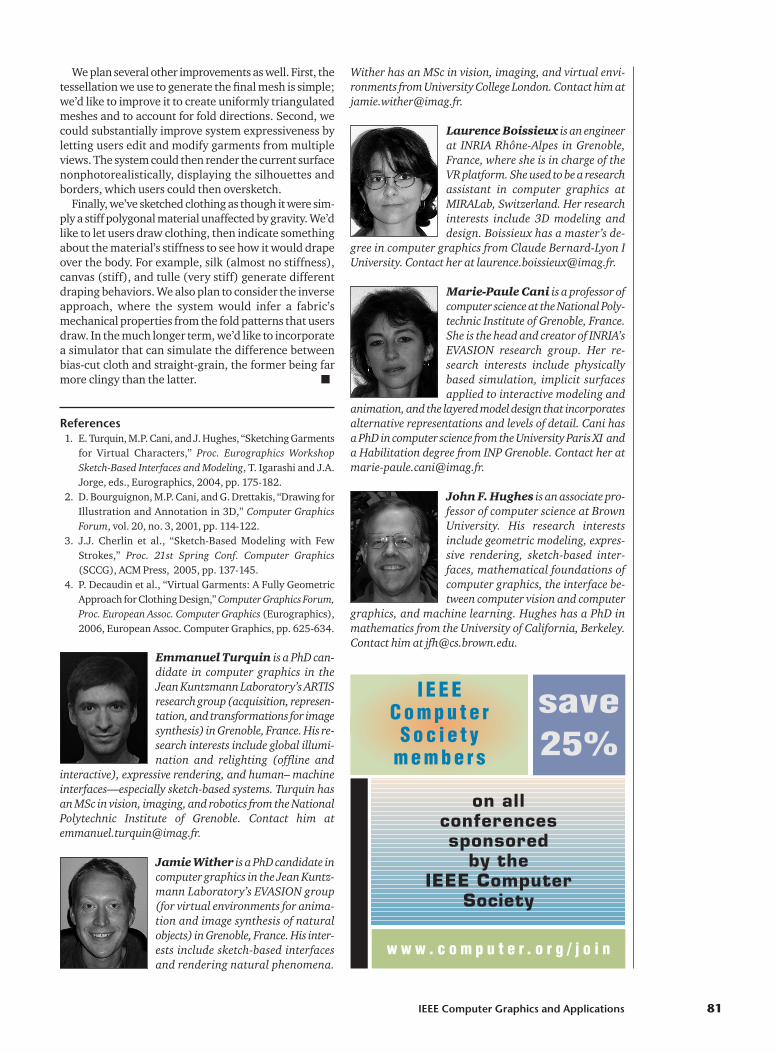
Jamie Wither is a PhD candidate incomputer graphics in the Jean Kuntz-mann Laboratory’s EVASION group(for virtual environments for anima-tion and image synthesis of naturalobjects) in Grenoble, France. His inter-ests include sketch-based interfacesand rendering natural phenomena.
Wither has an MSc in vision, imaging, and virtual envi-ronments from University College London. Contact him [email protected].
Laurence Boissieux is an engineerat INRIA Rhône-Alpes in Grenoble,France, where she is in charge of theVR platform. She used to be a researchassistant in computer graphics atMIRALab, Switzerland. Her researchinterests include 3D modeling anddesign. Boissieux has a master’s de-
gree in computer graphics from Claude Bernard-Lyon IUniversity. Contact her at [email protected].
Marie-Paule Cani is a professor ofcomputer science at the National Poly-technic Institute of Grenoble, France.She is the head and creator of INRIA’sEVASION research group. Her re-search interests include physicallybased simulation, implicit surfacesapplied to interactive modeling and
animation, and the layered model design that incorporatesalternative representations and levels of detail. Cani hasa PhD in computer science from the University Paris XI anda Habilitation degree from INP Grenoble. Contact her [email protected].
John F. Hughes is an associate pro-fessor of computer science at BrownUniversity. His research interestsinclude geometric modeling, expres-sive rendering, sketch-based inter-faces, mathematical foundations ofcomputer graphics, the interface be-tween computer vision and computer
graphics, and machine learning. Hughes has a PhD inmathematics from the University of California, Berkeley.Contact him at [email protected].
IEEE Computer Graphics and Applications 81
on all conferences sponsored
by the IEEE Computer
Society
w w w . c o m p u t e r . o r g / j o i n
save25%
I E E E C o m p u t e r
S o c i e t y m e m b e r s