3d modeling steps - sketch step 1 sketch geometry
TRANSCRIPT
3D Modeling Steps - Sketch
Step 1 Sketch Geometry
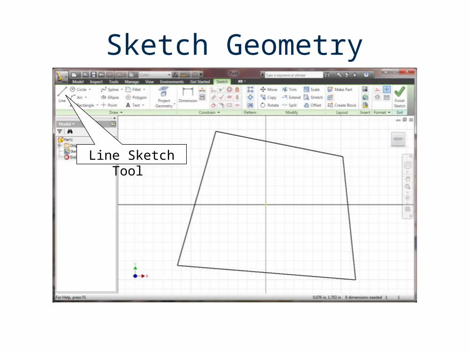
Sketch Geometry
Line Sketch Tool
3D Modeling Steps - Constrain
Step 1 Sketch Geometry Step 2 Constrain Geometry
A. Apply Geometric Constraints
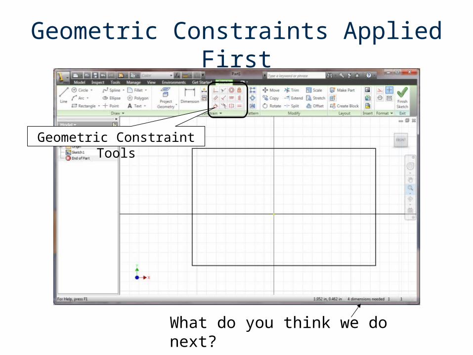
Geometric Constraints Applied First
Geometric Constraint Tools
What do you think we do next?
3D Modeling Steps - Constrain
Step 1 Sketch Geometry Step 2 Constrain Geometry
A. Apply Geometric Constraints B. Apply Dimension Constraints
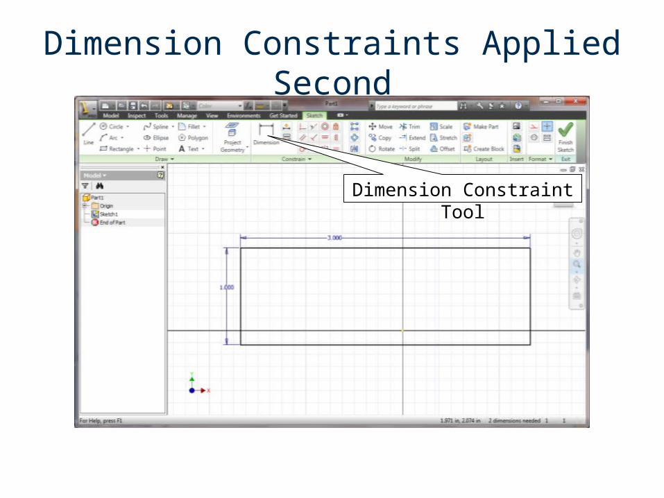
Dimension Constraints Applied Second
Dimension Constraint Tool
The geometry that has been constrained is a profile of an object.
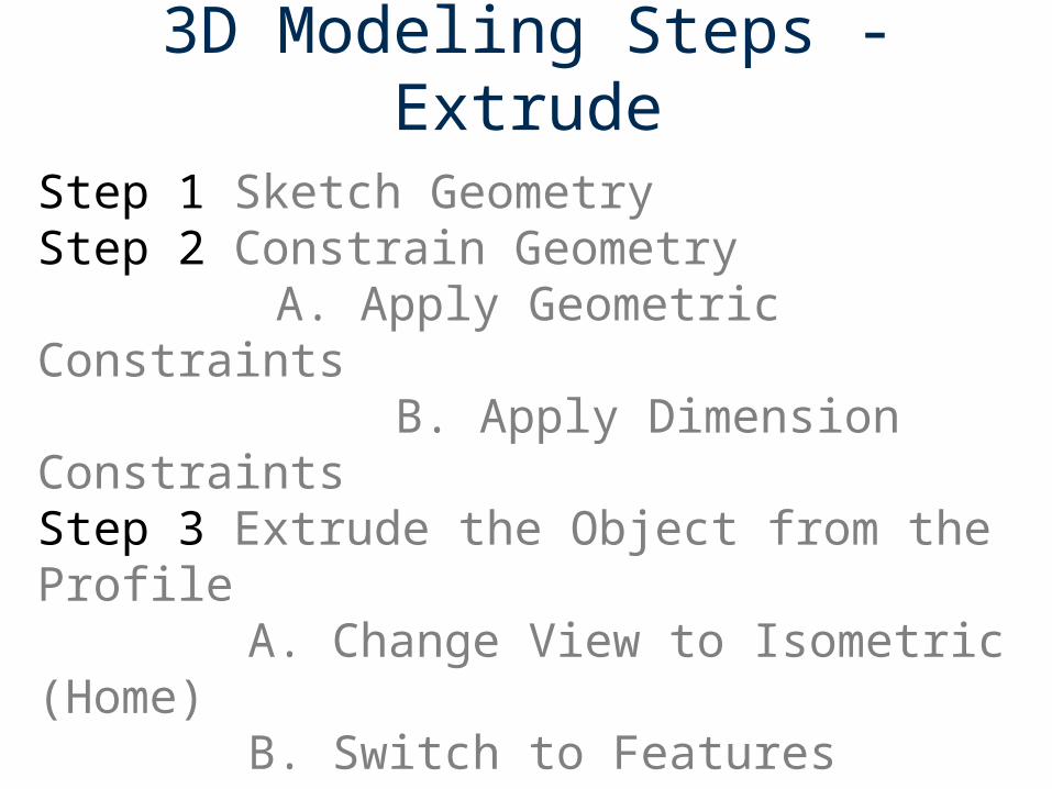
3D Modeling Steps - Extrude
Step 1 Sketch Geometry Step 2 Constrain Geometry
A. Apply Geometric Constraints B. Apply Dimension Constraints
Step 3 Extrude the Object from the Profile A. Change View to Isometric (Home)
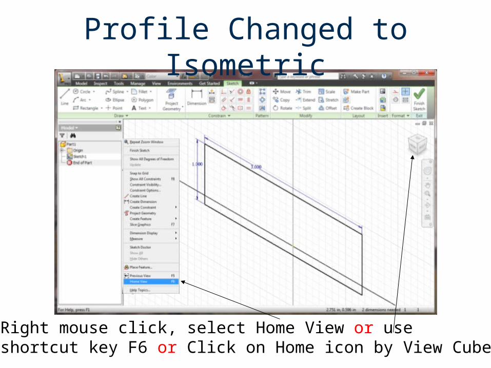
Profile Changed to Isometric
Right mouse click, select Home View or use shortcut key F6 or Click on Home icon by View Cube
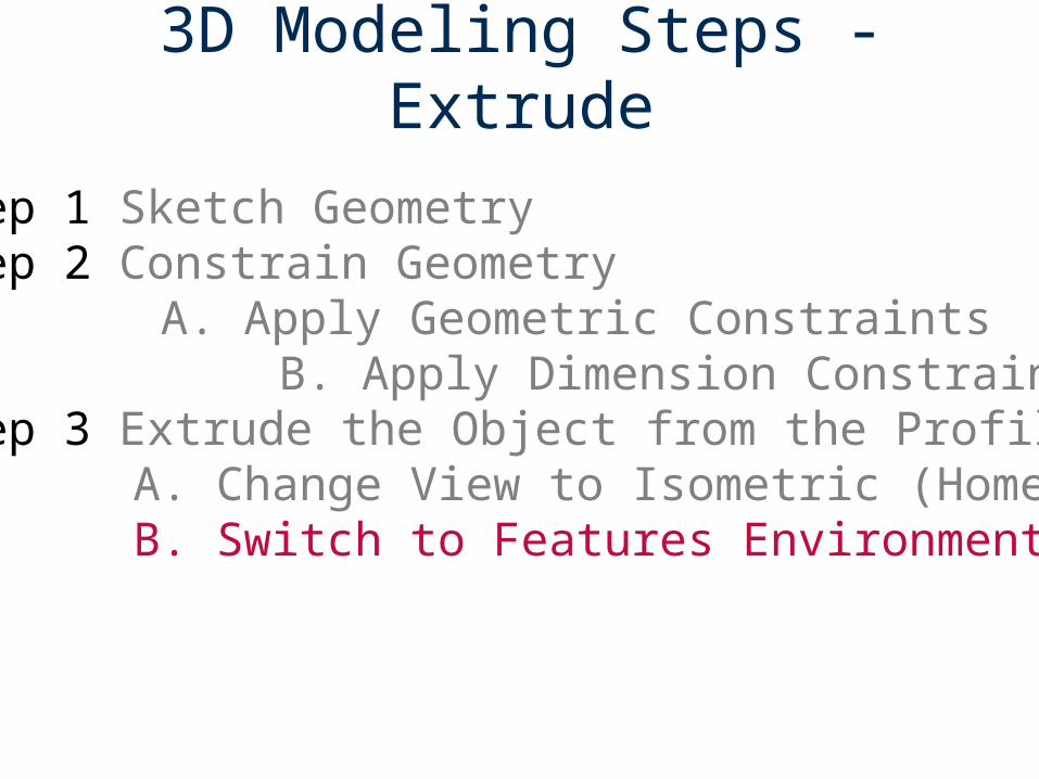
3D Modeling Steps - Extrude
Step 1 Sketch Geometry Step 2 Constrain Geometry
A. Apply Geometric Constraints B. Apply Dimension Constraints
Step 3 Extrude the Object from the Profile A. Change View to Isometric (Home)
B. Switch to Features Environment
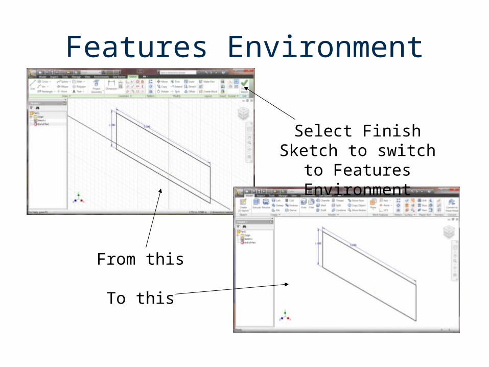
Features Environment
Select Finish Sketch to switch to Features
Environment
From this
To this
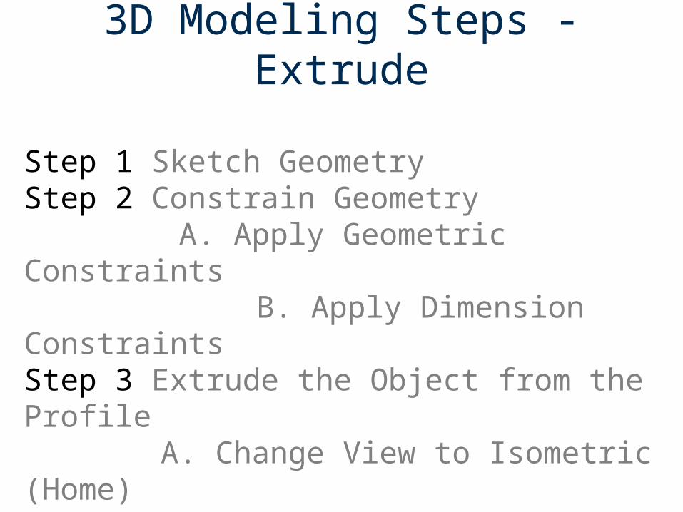
3D Modeling Steps - Extrude
Step 1 Sketch Geometry Step 2 Constrain Geometry
A. Apply Geometric Constraints B. Apply Dimension Constraints
Step 3 Extrude the Object from the Profile A. Change View to Isometric (Home)
B. Switch to Features EnvironmentC. Preview the Extrusion
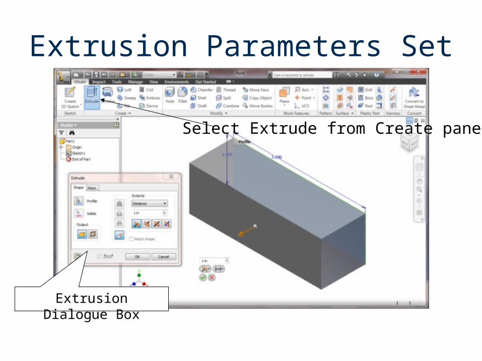
Extrusion Parameters Set
Extrusion Dialogue Box
Select Extrude from Create panel
3D Modeling Steps - Extrude
Step 1 Sketch Geometry Step 2 Constrain Geometry
A. Apply Geometric Constraints B. Apply Dimension Constraints
Step 3 Extrude the Object from the Profile A. Change View to Isometric (Home)
B. Switch to Features EnvironmentC. Preview the ExtrusionD. Apply Extrusion
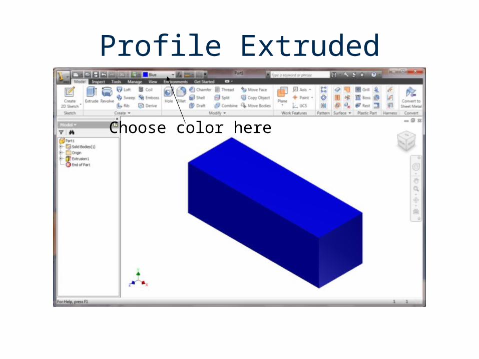
Profile Extruded
Choose color here
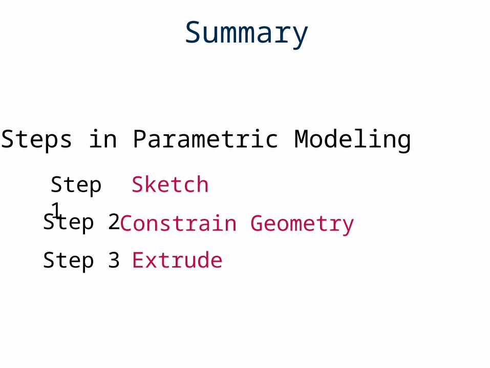
Summary
Step 1
Extrude
Constrain Geometry
Sketch
Step 3
Step 2
Steps in Parametric Modeling
Part 2
Parametric Modeling
Adding a Feature to a Solid Model
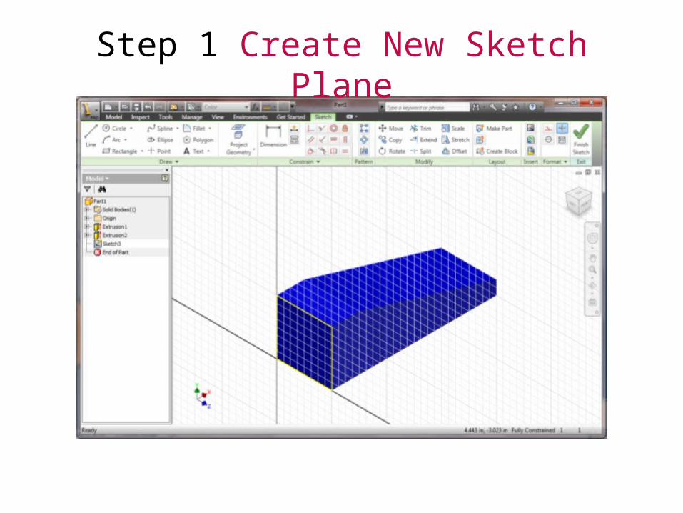
Step 1 Add Sketch Plane to surface on which geometry will be sketched
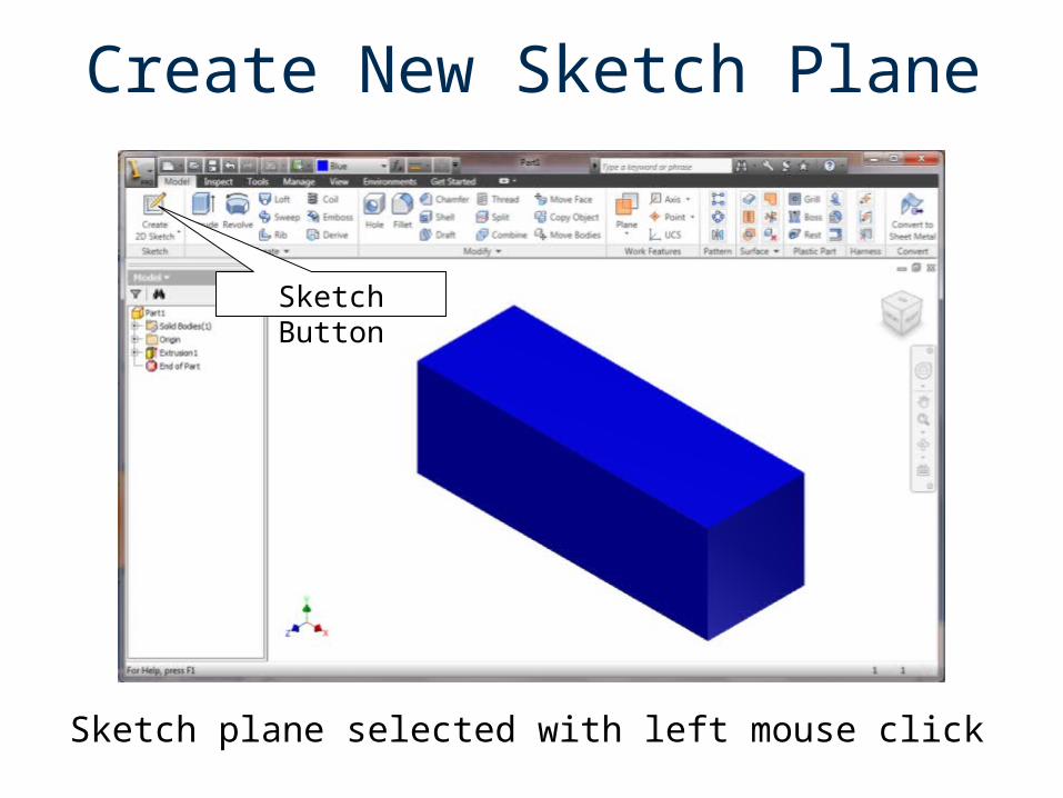
Create New Sketch Plane
Sketch plane selected with left mouse click
Sketch Button
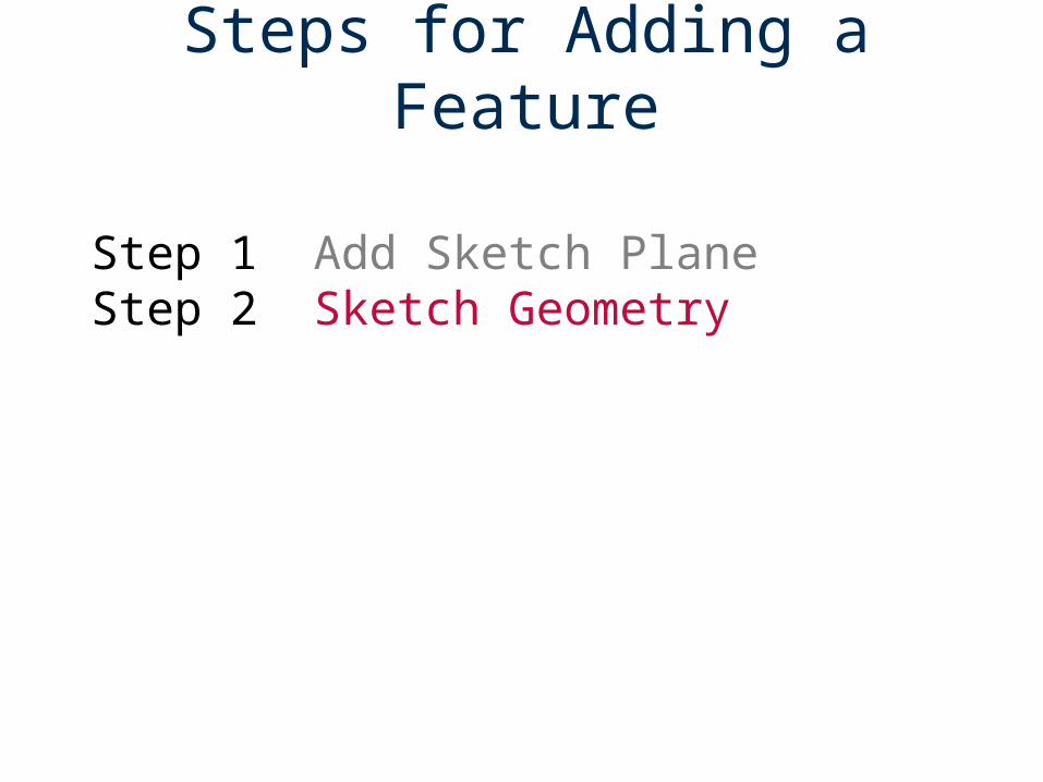
Steps for Adding a Feature
Step 1 Add Sketch PlaneStep 2 Sketch Geometry
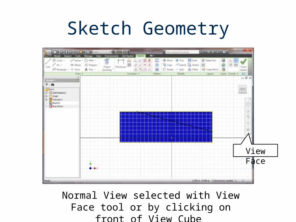
View Face
Sketch Geometry
Normal View selected with View Face tool or by clicking on front of View Cube
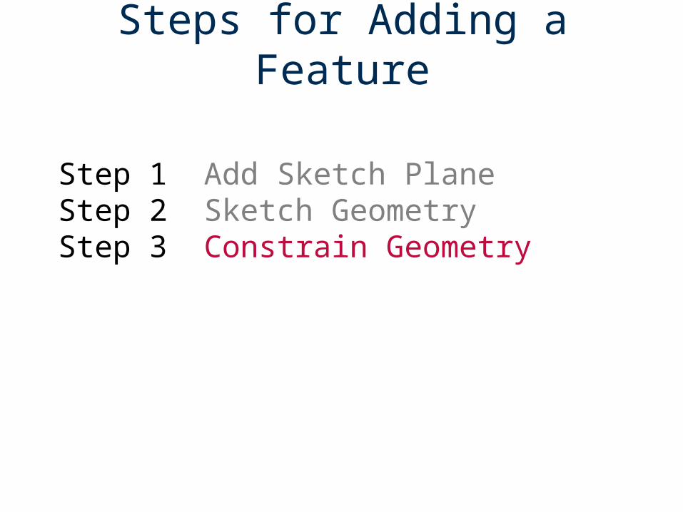
Steps for Adding a Feature
Step 1 Add Sketch PlaneStep 2 Sketch GeometryStep 3 Constrain Geometry
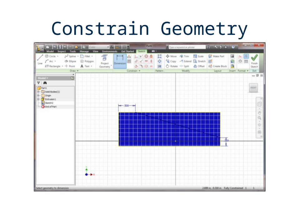
Constrain Geometry
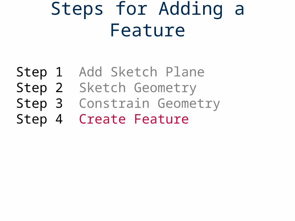
Steps for Adding a Feature
Step 1 Add Sketch Plane Step 2 Sketch GeometryStep 3 Constrain GeometryStep 4 Create Feature
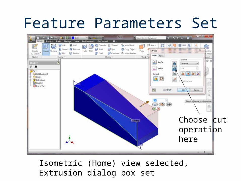
Feature Parameters Set
Isometric (Home) view selected, Extrusion dialog box set
Choose cut operation here
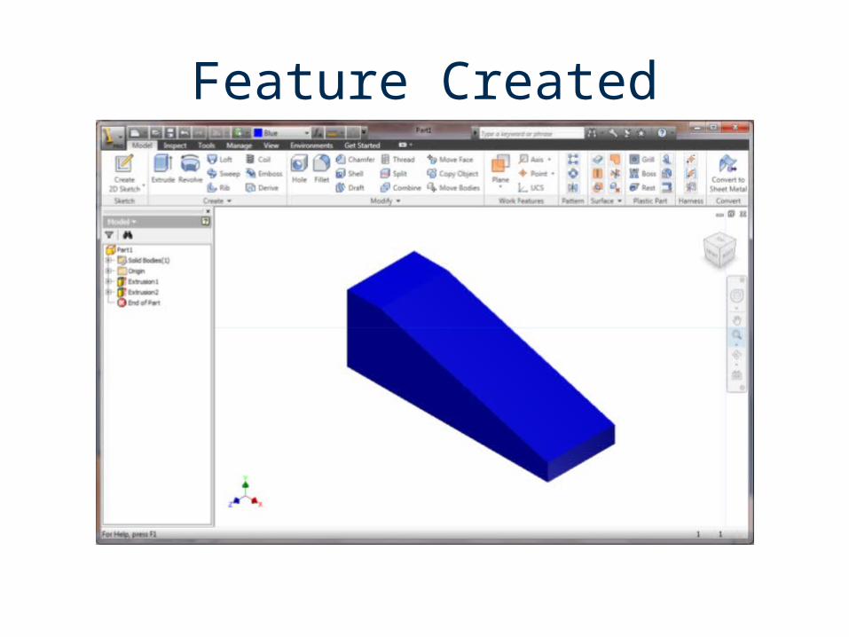
Feature Created
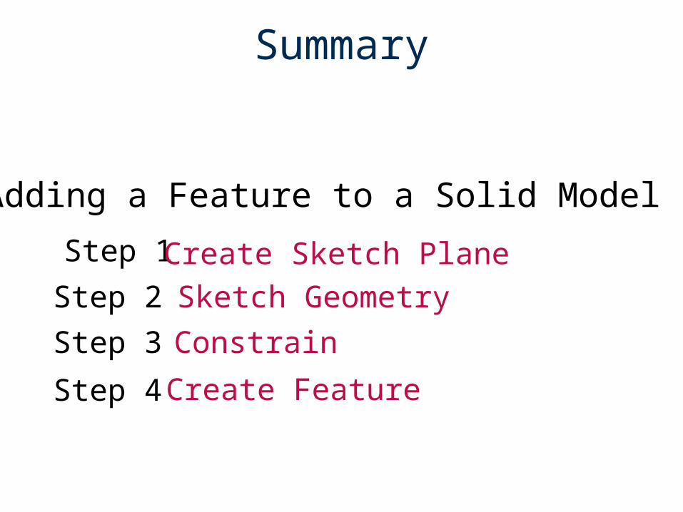
Summary
Step 1 Create Sketch Plane
Constrain
Sketch Geometry
Step 3
Step 2
Create Feature Step 4
Adding a Feature to a Solid Model

Let’s see it again…
…this time we will create a hole feature.
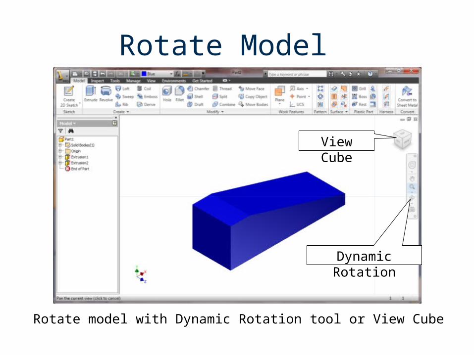
Rotate Model
Dynamic Rotation
View Cube
Rotate model with Dynamic Rotation tool or View Cube
Step 1 Create New Sketch Plane

Step 2 Sketch Geometry
This tool used to…
…create center point geometry
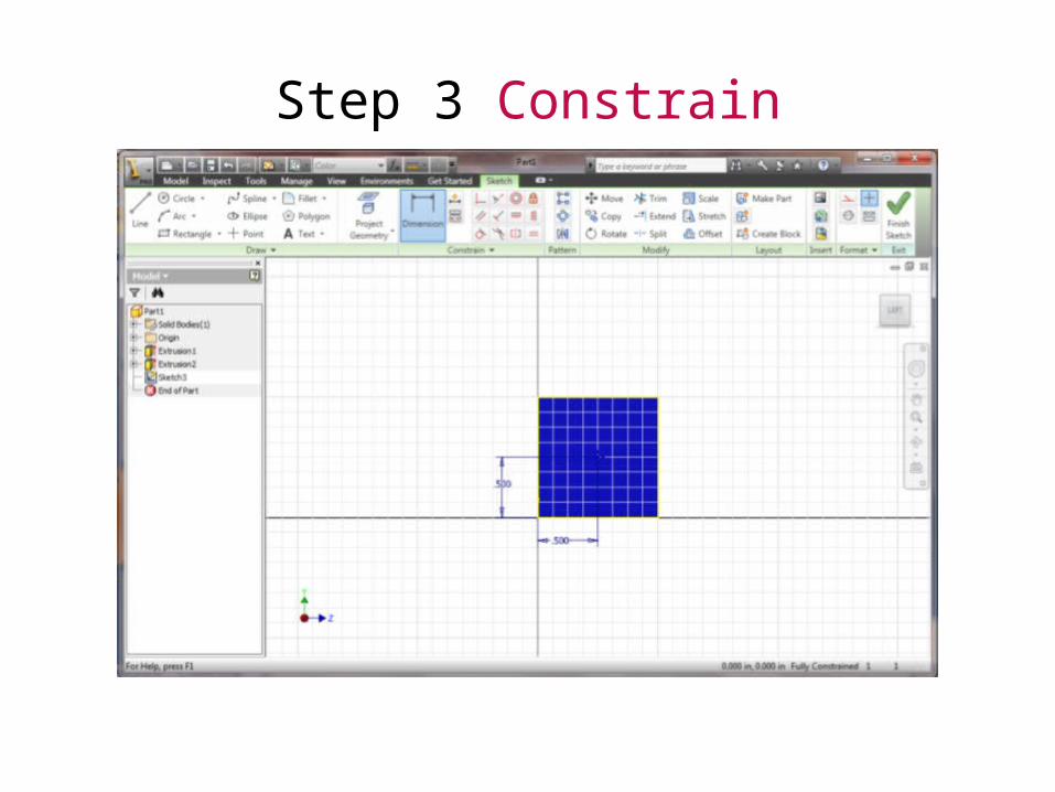
Step 3 Constrain
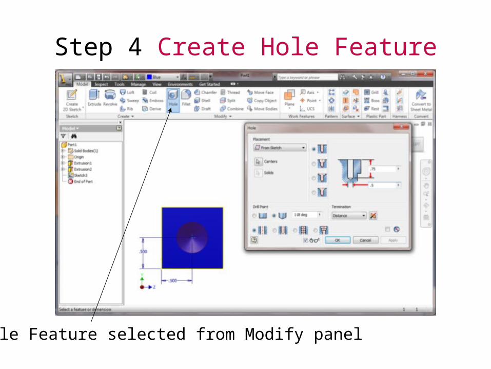
Step 4 Create Hole Feature
Hole Feature selected from Modify panel
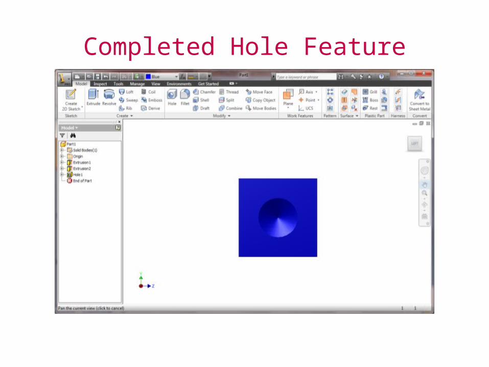
Completed Hole Feature
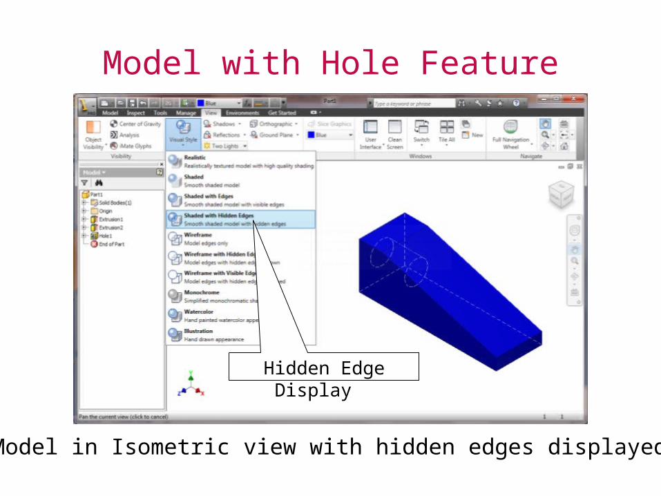
Model with Hole Feature
Model in Isometric view with hidden edges displayed
Hidden Edge Display
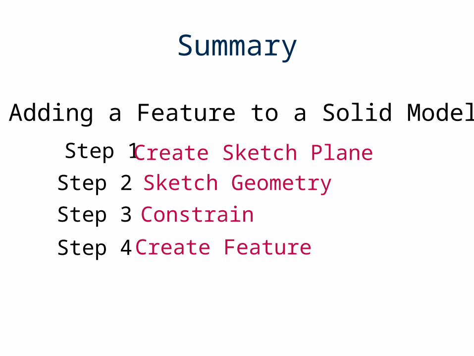
Summary
Step 1 Create Sketch Plane
Constrain
Sketch Geometry
Step 3
Step 2
Create Feature Step 4
Adding a Feature to a Solid Model
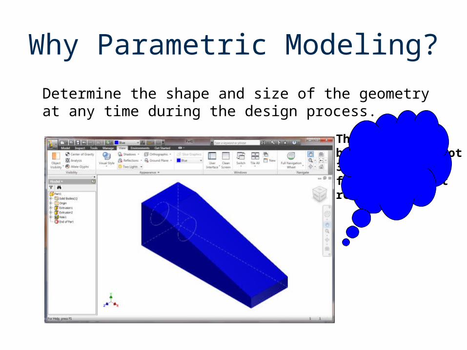
Why Parametric Modeling?
Determine the shape and size of the geometry at any time during the design process.
This part shouldbe 5 in. long, not3 in. How can wefix this withoutredrawing it?
Why Parametric Modeling?
Benefits– Shape before size– Geometric and dimension constraints used to
capture design intent– All files can be quickly updated– Existing data can be used for new designs– Quick design turn around