skeletal muscle tissue engineering system to … · 2 executive summary introduction skeletal...
TRANSCRIPT

Skeletal Muscle Tissue Engineering System to Mimic
In Vivo Development
A Major Qualifying Project Submitted to the Faculty of WPI in partial
fulfillment of the requirements for the Degree of Bachelor of Science
Authored By:
Alyssa Fidanza
Jonathan Fitzgibbon
Steven Greco Todd Pfizenmaier
Advisor:
Raymond Page
April 25th 2013

1
Abstract
Skeletal muscle atrophy can occur for a number of reasons including degenerative diseases
and age-related sarcopenia. Current pre-clinical studies for regeneration therapies are solely
reliant on animal models, which do not accurately mimic human tissue and chemistry. The
purpose of developing this device was to provide a reproducible manner of creating an in vitro
skeletal muscle model that will aid in preclinical therapy testing. The device was designed to
maintain a sterile environment for tissue culture, which provides anchorage, periodic strain, and
generates an electric field to stimulate contraction. The intended output of the device is the
controlled culture of a minimal functional unit of skeletal muscle that surpasses current standards
of in vitro and in vivo pre-clinical models.

2
Executive Summary
Introduction
Skeletal muscle tissue is one of the most prevalent tissues in the human body and is
responsible for all voluntary movement. This tissue is primarily composed of cells known as
myocytes that fuse during embryonic growth to form mature muscle fibers (Grefte et al. 2007).
There also exists a population of satellite progenitor cells in the basement membrane of the
tissue. These satellite cells may be activated to repair damaged tissue by re-entering the cell
cycle and differentiating into mature muscle cells thus functioning in muscle tissue formation.
However, the regenerative capacity of mature muscle tissue is somewhat limited, especially in
instances of intense damage such as that caused by severe trauma or extensive muscular atrophy
(Grefte et al. 2007). In instances of intense muscle tissue damage the tissue is replaced by a
combination of newly formed muscle fibers and collagenous scar tissue, which is weaker than
the previously healthy tissue. Muscle regeneration may also be seen to decrease concurrent with
aging as the satellite cell population decreases and the cells become less proficient at remodeling
tissue.
A consistent means of evaluating clinical therapies is necessary to test and study various
treatments aimed at enhancing muscle regeneration. Tissue engineering is a sought-after
mechanism of accomplishing this goal as it would provide for simple, reproducible testing and
would remove the need to move straight to in vivo testing in animal or human subjects. The
development of a tissue engineered skeletal muscle construct would ideally be the minimum
functional unit representative of a mature muscle and would serve as a platform on which to
efficiently assess the effectiveness of therapeutic treatments for muscle regeneration.
Skeletal muscle tissue is constantly undergoing stimulation during and after its development.
Muscle tissue is anchored to bone with tendons to assure its security within the body. All
voluntary motion is then directed by voltages discharged by motor neurons adjoined to the tissue.
Muscle movements involve contractions and relaxations, which may be characterized by
muscular stretching that aligns the fibers that make up the tissue (Kjær et al. 2006). In order for
an in vitro tissue engineering skeletal muscle system to work, it must be able to similarly provide

3
these electrical and mechanical stimuli to the generated tissue constructs, as well as an anchoring
point, so that the maturation process mimics that in the body.
Design
The design for a system that would facilitate the development of functional tissue engineered
muscle constructs should promote tissue self-assembly without the use of a scaffold to direct
myocyte fusion. Myocytes are cued to fuse together with the proper growth factors to incite
terminal differentiation. In the body, skeletal muscle tissue is anchored to bone via tendon
attachment; this system allows tension to be provided to muscle so that the muscle tissue may
strengthen while it matures. The in vitro tissue constructs should have points of anchorage as
well to provide for this same tension. Finally, the aforementioned electrical and mechanical
stimuli are very important considerations in this tissue engineering system to accurately form
functional tissues.
Several different designs were brainstormed that would permit tissue self-assembly
surrounding points of anchoring and that would also provide for mechanical and electrical
stimulation in a controlled manner during development. After comparing the various options to
determine the best and most feasible approach within our constraints, the team elected to use a
design that actuated with a lever arm protruding through a rubber septum that was inserted into
the culture dish lid. The use of a rubber septum allowed for the lever arm to attach to the
external motor and also pass through into the dish to actuate the tissue construct while
maintaining sterility throughout the interface. The design was further supplemented by two
platinum tip electrodes for electrical stimulation.
The complete device design is based upon the use of a 35mm cell culture dish. Within this
dish is an actuation system that utilizes two interlocking plates, one of which is held stationary
while the other attaches to the lever arm and may move unilaterally. These posts protrude from
each of the plates, and serve as points of anchorage for the tissue construct, permitting a linear
region of tissue to exist in the midst of the device. The posts were created from polycarbonate to
allow for deflection
To direct the formation of the tissue construct, and to mitigate stress concentrations, a mold
was designed to promote a consistent cross sectional area throughout tissue construct, while
simultaneously allowing the tissue to be anchored about the aforementioned posts. A reusable

4
PDMS mold was used for the negative mold, which could easily be autoclaved before the
creation of a sterile agarose mold. Agarose was chosen for cell culture due to its noted low
surface affinity for cell-adhesion, allowing for self-assembly of the differentiating muscle fibers.
The mold fits around the posts and enables the motion of the actuating plate to be directly
translated into strains within the tissue.
In order to produce controllable, periodic strains, a linear actuating stepper motor was
attached to the lever arm. An Arduino microcontroller and driver were placed on a protoboard to
allow for facile programming and control of the motor. This set up allowed for easy selection of
strain magnitude, as well as rate of application.
Testing and Desired Results
Several tests were developed to test the functionality of the device. The design had to
repeatedly and accurately strain tissue to a 10% greater length (+0.5 mm) comparative to its
original length (5.0 mm). This was able to be verified through photos and basic measurement
tools.
Programming validation for the motor was also a simple procedure. The desired outcome was
for the motor to stretch the muscle over 100ms in time, and at a frequency of 2 seconds.
Proof of concept testing was designed to ensure the device would have the intended results.
The device was designed to facilitate fiber alignment through processes similar to what occurs
naturally within the body. Since the device used two different methods, electric current and
mechanical actuation, to align the fibers, facilitated by anchoring posts, a controlled experiment
was designed to observe the effects of each method individually. The first procedure called for
C2C12 myoblasts to be seeded into the mold without any post anchoring at a concentration of 1
million cells throughout the mold. These cells were proliferated in DMEM with 10% FCS
solution, and differentiation would be initiated two days before seeding by using DMEM with
2% horse serum. They were then allowed to develop for two days before seeding into the mold.
No stimulation would be given to these control cells, and alignment would be observed under a
microscope.
To observe the effects of the anchoring on the muscle tissue development, the cells would
again be seeded into the mold using the same culture procedures. This time however, two of the
polycarbonate posts would be placed into the mold to allow for the cells to anchor themselves.

5
Again, no stimulation would be given to the cells. Alignment would be observed under a
microscope.
In attempting to test the system as a complete functional unit, a number of design flaws were
discovered that ultimately precluded device from working as intended. Of these, the greatest
issue found was that the tissue molding system could not easily be removed from the culture dish
without damaging or losing the tissue construct. Moderate tissue formation was seen in the dish
but this was not able to be successfully stimulated in such a manner to accurately replicate in
vivo development.
Conclusion
After completion of the project, we were able to determine that the separate mechanisms
designed for our system were functional, but further design modifications are necessary to
combine them into one working unit. The most prominent issue faced was preserving the safety
and integrity of the tissue while extracting the agarose gel mold from the petri dish, an obstacle
that could not be overcome within the time limits. However, the tissue molding system,
mechanical stimulation mechanism, and electrical stimulation mechanism were all confirmed on
individual bases to function as desired. In applying certain key design modifications during
future project iterations this design concept should prove to be fully functional and successfully
promote biomimetic skeletal muscle tissue formation.

6
Table of Contents
Abstract ......................................................................................................................................1
Executive Summary ....................................................................................................................2
Introduction........................................................................................................................................ 2
Design ................................................................................................................................................. 3
Testing and Desired Results ................................................................................................................ 4
Conclusion .......................................................................................................................................... 5
Table of Contents .......................................................................................................................6
Table of Figures ........................................................................................................................10
Table of Tables .........................................................................................................................12
Chapter 1: Introduction ............................................................................................................13
Chapter 2: Literature Review ....................................................................................................15
2.1 Muscle Physiology................................................................................................................... 15
2.1.1 Skeletal Muscle Formation and Maturation ....................................................................... 15
2.1.2 Structure and Function of Skeletal Muscle Tissue .............................................................. 16
2.1.3 Regeneration of Skeletal Muscle Tissue ............................................................................. 19
2.2 Clinical Need, Significance of Tissue Engineering and Skeletal Muscle Applications ................... 20
2.2.1 Tissue Engineering Background ............................................................................................ 20
2.2.2 Clinical Significance of Skeletal Muscle Tissue Engineering .................................................... 21
2.2.3 Need for in vitro Skeletal Muscle Model ............................................................................... 22
2.3 Potential Methods and Materials ............................................................................................... 23
2.3.1 Tissue Scaffolds .................................................................................................................... 23
2.3.1.1 Gels ............................................................................................................................................. 24
2.3.1.2 Collagen ...................................................................................................................................... 24
2.3.1.3 Fibrin .......................................................................................................................................... 24
2.3.1.4 Disadvantages of Scaffolds .......................................................................................................... 25
2.3.2 Creating 3D Tissue Constructs .............................................................................................. 25

7
2.3.3 Mechanical Stimulation ........................................................................................................ 26
2.3.4 Electrical Stimulation ............................................................................................................ 27
Chapter 3: Project Strategy ......................................................................................................29
3.1 Initial Client Statement ............................................................................................................... 29
3.3 Design Objectives ....................................................................................................................... 30
3.3.1 Tailored Objectives ............................................................................................................... 30
3.4 Constraints.................................................................................................................................. 31
3.5 Revised Client Statement ............................................................................................................ 32
3.6 Project approach......................................................................................................................... 32
3.6.1 Develop Cell Culture Techniques .......................................................................................... 32
3.6.2 Develop Gel Mold ................................................................................................................. 32
3.6.3 Develop Mechanical Design/Procedures ............................................................................... 33
3.6.4 Develop Electrical Design/Procedures................................................................................... 33
3.6.5 Proof of Concept Testing without cells .................................................................................. 33
3.6.6 Total Proof of Concept Testing.............................................................................................. 34
Chapter 4: Design Alternatives .................................................................................................35
4.1 Introduction ................................................................................................................................ 35
4.2 Needs Analysis ............................................................................................................................ 35
4.3 Functions-Means Analysis and Design Specifications ................................................................. 36
4.4 Design Alternatives ..................................................................................................................... 37
4.4.1 Design Alternative 1 - Magnet .............................................................................................. 37
4.4.2 Design Alternative 2 - Hydraulic Syringe Pump ...................................................................... 39
4.4.3 Design Alternative 3 – Moving Lid ........................................................................................... 40
4.4.4 Alternative Design 4 - Lever Design.......................................................................................... 42
4.5 Final Design................................................................................................................................. 43
4.6 Feasibility Studies ....................................................................................................................... 44
4.6.1 Co-Culturing with Fibroblasts ................................................................................................ 44
4.6.2 Anchoring Posts and Mold Shape.......................................................................................... 45
4.7 Preliminary Data ......................................................................................................................... 47
4.7.1 Cell Culture Standards .......................................................................................................... 47
4.7.2 Strain Distance ..................................................................................................................... 48

8
4.7.3 Sterility ................................................................................................................................. 48
4.7.4 Materials .............................................................................................................................. 48
Chapter 5: Manufacturing ........................................................................................................49
5.2 Material Choices ......................................................................................................................... 51
5.3 Stepper Motor Modification ....................................................................................................... 52
5.3.1 Back Plate ............................................................................................................................. 53
5.4 Base ............................................................................................................................................ 53
5.5 Posts ........................................................................................................................................... 54
5.6 Dish Inserts ................................................................................................................................. 55
5.7 Dish Cover Modifications ............................................................................................................ 56
5.8 Electrodes ................................................................................................................................... 57
5.9 Lever-Motor Connection ............................................................................................................. 58
Chapter 6: Motor Wiring and Programming .............................................................................59
Chapter 7: Methodology ..........................................................................................................60
7.1 Preliminary Muscle Cell Culture .................................................................................................. 60
7.1.1 Cell Culture ........................................................................................................................... 60
7.2 Mold Creation and Validation ..................................................................................................... 62
7.2.1 ABS Plastic Mold ................................................................................................................... 62
7.2.2 PDMS Mold Process.............................................................................................................. 63
7.2.3 – Agarose Mold Construction ............................................................................................... 64
7.3 Proof of Concept Testing ............................................................................................................. 64
7.3.1 Mechanical Proof of Concept ................................................................................................ 65
7.3.2 Electrical Proof of Concept Testing ....................................................................................... 65
7.4 3D Tissue Construct Development .............................................................................................. 66
Chapter 8: Testing and Validation ............................................................................................67
8.1 Mechanical Stimulation Proof of Concept................................................................................... 67
8.2 Electrical Stimulation Proof of Concept ...................................................................................... 67
8.3 Sterilization ................................................................................................................................. 67
8.4 Bromodeoxyuridine Staining for Cell Proliferation ..................................................................... 68
8.4 Cell Seeding in Agarose Tissue Mold ........................................................................................... 71

9
Chapter 9: Project Impact .........................................................................................................72
9.1 Manufacturing ............................................................................................................................ 72
9.2 Sustainability .............................................................................................................................. 72
9.3 Economics ................................................................................................................................... 73
9.4 Ethics .......................................................................................................................................... 73
9.5 Health & Safety ........................................................................................................................... 73
Chapter 10: Discussion .............................................................................................................75
10.1 Stimulation Mechanisms .......................................................................................................... 75
10.2 Tissue Formation ...................................................................................................................... 76
10.3 Overall Design ........................................................................................................................... 76
Chapter 11: Recommendations and Conclusions .....................................................................78
11.1 Tissue Mold System Recommendations .................................................................................... 78
11.2 Motor Recommendations ......................................................................................................... 79
11.3 Petri Dish Recommendations .................................................................................................... 79
11.4 Conclusions ............................................................................................................................... 80
References ................................................................................................................................81
Appendix A: Pairwise Comparison Chart ..................................................................................85
Appendix B: Objectives Tree.....................................................................................................86
Appendix C: Budget ..................................................................................................................87
Appendix D: Cell Culture Protocols ...........................................................................................88
Appendix E: Cell Culture Medium Components........................................................................92
Appendix F: Immunocytochemistry Protocols ..........................................................................94
Appendix G: Arduino Uno Microcontroller Programming ........................................................95

10
Table of Figures
Figure 1: Muscle Fiber Structure (Jeon, JS. Muscle Fiber. 2012.) .............................................. 16
Figure 2: Regions of a Sarcomere during Relaxation and Contraction (Shreastha, 2010.) .......... 17
Figure 3: Skeletal Muscle Tissue and ECM Structure (Structure of a Skeletal Muscle, 2012.) ... 18
Figure 4: Regeneration of Damaged Muscle Tissue (Burks et al. 2011) ..................................... 19
Figure 5: In Vitro Myofiber Development. Static development is displayed on the left side, and
mechanically stimulated muscle is shown on the right. SEM imaging was used for the bottom
images and H&E stain used for the top images. (Moon et al. 2008). .......................................... 27
Figure 6: Myofibers enhanced with an electrical stimulation regimen. The top figure displays
myofibers developed without stimulation, and the bottom figure displays fibers that have aligned
better as a result of the stimulation (Fujita et al., 2007). ............................................................. 28
Figure 7: Magnet Design ........................................................................................................... 38
Figure 8: Dogbone Tissue Anchoring system with Anchoring Posts .......................................... 39
Figure 9: Hydraulic Syringe Pump ............................................................................................ 40
Figure 10: Movable Lid Design ................................................................................................. 41
Figure 11: Lever Design ............................................................................................................ 42
Figure 12: Cone Shaped Post Design ......................................................................................... 45
Figure 14: Top View of Well Shapes ......................................................................................... 46
Figure 15: Manufactured Mold for PDMS Casting .................................................................... 47
Figure 16: Pictured on the left is the stationary dish insert, and pictured on the left is the moving
dish insert. ................................................................................................................................. 49
Figure 17: Translucent Top View of Full Design ....................................................................... 50
Figure 18: Model of Complete Design ....................................................................................... 51
Figure 19: Stepper Motor Modification ..................................................................................... 53
Figure 20: Stainless Steel Back Plate ......................................................................................... 53
Figure 21: Fixated Motor and Base............................................................................................ 54
Figure 22: Anchoring Post Production Method .......................................................................... 55
Figure 23: Fully Assembled Dish Inserts with Posts .................................................................. 56
Figure 24: Modified Dish Cover and Full Dish Assembly ......................................................... 57
Figure 25: Electrode Assembly Diagram ................................................................................... 58

11
Figure 26: Full Mechanical Actuation Assembly ....................................................................... 58
Figure 27: Motor WIring Diagram (Stepping Up to the Challenge, 2013). ................................. 59
Figure 29: Electrical Stimulation Proof of Concept Testing ....................................................... 66
Figure 30: BrdU Staining of C2C12 Cells Cultured in Proliferation Medium ............................. 69
Figure 31: BrdU Staining of C2C12 Cells Cultured in Differentiation Medium ......................... 70
Figure 32: Phase Contrast Microscopy of Proliferating (left) and Differentiating (right) C2C12
cells .......................................................................................................................................... 70
Figure 33: Tissue in Dish 12h After Seeding ............................................................................. 71

12
Table of Tables
Table 1: Summary of Electrical Stimulation Studies .................................................................. 28
Table 2: Functions-Means Chart ................................................................................................ 36
Table 3: Design Comparison ..................................................................................................... 44
Table 4: Bill of Materials .......................................................................................................... 51

13
Chapter 1: Introduction
One of the most predominant tissues in the human body is skeletal muscle tissue.
Skeletal muscle accounts for up to 40% of the body’s mass and is responsible for all voluntary
locomotion (Delbono et al, 2007). Because everyday body function is so heavily dependent on
skeletal muscle, loss of this tissue can be detrimental to quality of life.
One of the most astounding features of skeletal muscle is its capacity for regeneration.
Minor damage or injuries that occur to the tissue can be repaired by myogenic precursor cells,
commonly referred to as satellite cells. These cells, which normally lie dormant in the basement
membrane of the muscle, are activated by the release of Hepatocyte Growth Factor upon damage
to the muscle fiber (Grefte et al. 2007). Once the satellite cells are recruited to the damaged area,
they attach to the site of injury, and differentiate into mature and functional myofibers. The new
muscle tissue that forms from this process may be vascularized and innervated to integrate with
the surrounding tissue and bring it back to full functionality. Unfortunately, it is in cases of
serious damage or trauma, atrophy, or disease, that skeletal muscle is not completely recovered.
Fibrous tissue is recruited to the site instead, which greatly limits the functional capacity of the
muscle tissue. The end result will be scarring and a partial loss of tissue function.
Efforts to develop therapeutic treatment for muscle loss have led to the field of skeletal
muscle tissue engineering. Research in this field attempts to surmount the shortcomings and
develop viable means of regenerating muscle tissue. This is accomplished by developing muscle
tissue constructs in vitro that mimic natural tissue structure and function and may be used in
therapeutic testing. However, the field of skeletal muscle tissue engineering is not without flaw.
Problems in the field include the difficult procedures that are required to form and subsequently
reproduce tissue constructs, and that the tissue does not possess nearly the same strength as does
in vivo muscle tissue. The complexity of the in vivo environment also proves quite difficult to
mimic in an in vitro laboratory setting, adding additional challenges to this goal.
Many tissue constructs that have been developed in vitro are done so on synthetic
scaffolds that provide structure and support for the cells. While this technique produces viable
tissue, it is not ideal as it does not mimic natural tissue formation, and does not achieve densities

14
found in human tissue. A more preferable alternative involves directing muscle cells to self-
assemble into a myofiber and generate their own extracellular matrix for support.
After conducting a number of preliminary engineering design assessments, a design
proposal was developed to address these needs. This design attempts to allow for self-assembly
of muscle cells into a fully formed muscle fiber that will then be mechanically and electrically
stimulated to direct fiber maturation and test the functionality of the tissue construct. Further
research and analysis directed the development of the tissue engineering system design. In this
system, a gel mold was used to direct tissue self-assembly in conjunction with the proper and
necessary growth factors. The tissue construct was anchored to two posts to provide support and
tension during formation. Mechanical and electrical stimulation aided in alignment and
maturation.

15
Chapter 2: Literature Review
Skeletal muscle is a complex tissue system that is vital to everyday human movement.
Unfortunately, there are many cases in which this tissue may be afflicted with a number of
adverse conditions that damage and weaken it. Due to its limited regenerative capacity, skeletal
muscle is not able to fully recover from more intense injury and alternative means of
rehabilitating this tissue are required. The overarching aim of this project is to develop a means
of accurately recapitulating fully formed skeletal muscle tissue in vitro. This chapter examines
the background information pertaining to skeletal muscle tissue and clinical efforts to develop
muscle tissue constructs for therapeutic testing.
2.1 Muscle Physiology
The human body is composed of three major muscle systems: skeletal muscle: smooth
muscle, and cardiac muscle. Controlled by the autonomic nervous system, smooth muscle and
cardiac muscle are both involuntary tissues. Cardiac muscle is responsible for contractions of
the heart and smooth muscle controls all other involuntary mechanisms of the body, including
food digestion and waste excretion. Skeletal muscle, directed by the somatic nervous system, is
responsible for all voluntary motion in the body; it governs locomotion and requires cognitive
control to function (Buckingham et al. 2003).
2.1.1 Skeletal Muscle Formation and Maturation
Along the neural tube of developing vertebrate embryos are somites, which are divisions
of mesoderm that will become the myotome, dermatome, and sclerotome as the embryo
develops. Of these, the myotome is the segment that will differentiate into muscle tissue, with
the other two forming the dermis and vertebrae, respectively. The epaxial region of the
myotome gives rise to the back muscles of the body, and the remaining muscles stem from the
hypaxial region. During this time, muscle progenitor cells are seen to delaminate from the
hypaxial myotome and migrate to the locations that are to become the dorsal and ventral muscle
masses (Buckingham et al, 2003).
The earliest stages of myotome development occur with the delaminating progenitor
cells. Delamination, as well as migration, of these cells is dependent on the presence of c-met, a

16
tyrosine kinase receptor that interacts with hepatocyte growth factor (HGF) to outline the path of
migration (Buckingham et al., 2003). The delaminating progenitor cells begin to down-regulate
the transcription factor Pax3 and activate myogenic regulatory factors (MRFs), subsequently
becoming myoblast cells. The myoblasts then begin expressing a number of different factors
that lead to differentiation into myocytes that fuse together to form a continuous layer of muscle
fibers that is the myotome (Grefte et al., 2007).
During the formation of the myotome, another group of cells also delaminates and
migrates to this same developing region of the body. These cells express Pax3 as well as Pax7
but do not express any of the same myogenic factors present into the cells that are to become
myocytes. These cells instead differentiate into the satellite cells of the muscle tissue (Grefte et
al., 2007).
2.1.2 Structure and Function of Skeletal Muscle Tissue
The standard muscle cell is known as the myocyte. Myocytes develop from myoblasts
during embryonic stages of growth and fuse together to form functional muscle fibers. As a
result of this fusion process, myocytes are multinucleated. These cells are composed of many
myofibrils, rod-shaped chains segmented into sarcomeres. Sarcomeres themselves are the basic
contractile functional units of muscle tissue, and they are made up of contractile actin and
myosin myofilaments. The myofibrils are aligned in parallel to form the muscle fibers, with
thousands of myofibrils making up each fiber. Muscle fiber structure may be seen in Figure 1.
Figure 1: Muscle Fiber Structure (Jeon, JS. Muscle Fiber. 2012.)

17
Muscular contraction is controlled by motor neurons. At the neuromuscular junction of
each muscle fiber, a motor neuron axon attaches to the motor end plate. The neuron generates an
action potential that is passed through the axon terminal to the motor end plate. Once sensed,
this causes calcium channels to open, allowing for Ca2+
ions to pass into the cell. The
neurotransmitter acetylcholine is then released by exocytosis and binds to receptors at the motor
end plate, opening channels that allow sodium ions to move inward and potassium ions to exit
the cell. Different concentrations of sodium and potassium pass through the channels, creating
local depolarization that diffuses across the membrane surface and instigates muscle contraction.
During this contraction period, the thick and thin filaments pull on one another as regions known
as the I-bands and H-zone of the sarcomere shorten, causing the Z-lines to move closer together,
as seen in Figure 2.
Figure 2: Regions of a Sarcomere during Relaxation and Contraction (Shreastha, 2010.)
While myocytes and satellite cells are considered the primary components of skeletal
muscle tissue, there are a number of additional constituents present. Along with the
aforementioned motor neurons that stimulate contraction, blood vessels run throughout and
supply necessary nutrients to the cells, and there is an extensive extracellular matrix (ECM) that
provides a number of functions for the tissue. Specifically, the ECM provides for cell
attachment, migration, proliferation, and differentiation. It is also used in bearing loads applied

18
to muscle tissue and has been implicated to function in response to muscular disease and injury.
Three layers of skeletal muscle ECM exist, the first of which is the endomysium. This layer of
ECM surrounds individual myofibers and serves as the load-bearing network on these fibers.
The next layer is the perimysium; this layer is largely undefined but it is known to surround
bundles of myofibers, known as fascicles. Finally, the epimysium encases the entirety of the
muscle (Gillies et al., 2011). The coupled structure of skeletal muscle tissue and extracellular
matrix is seen in Figure 3.
Figure 3: Skeletal Muscle Tissue and ECM Structure (Structure of a Skeletal Muscle, 2012.)
The main structural element of skeletal muscle ECM is collagen, with collagen type I and
III being the predominant isoforms in fully developed tissue. A small amount of elastin is also
present to provide for elastic behavior in the tissue (Kjær, 2003). Several proteoglycans, highly
glycosylated protein molecules, have additionally been demonstrated as very important to the
development of skeletal muscle tissue and ECM. The proteoglycan decorin, consisting of a
glycosaminoglycan chain of chondroitin sulfate and dermatan sulfate, has been proven to interact
with collagen and direct the formation of the collagen fibrils. Heparan sulfate proteoglycans
such as syndecan and glypican are verified as important in tissue development, with syndecan
serving as a differentiation inhibitor that is highly expressed early in cell development and down-
regulated later on, and glypican displaying the opposite pattern and helping stimulate
differentiation. Additional proteins that have been shown to be important in the development of
the ECM are integrins; it has been shown that integrins are largely responsible for directing
myoblast migration and adhesion to the extracellular matrix (Velleman, 1999).

19
2.1.3 Regeneration of Skeletal Muscle Tissue
Whereas many other tissues in the body are fully capable of regenerating themselves over
time, skeletal muscle tissue does not possess this same capacity. In the event that the injury to
muscle tissue is relatively low and there is minimal volumetric muscle loss, the muscle satellite
cells will be able to fully remodel and repair the tissue; if the extent of the damage is too great
however, full regeneration will not occur. Regardless, muscle tissue restoration is a multi-step
process consisting of degenerative and regenerative phases.
Necrosis of muscle fibers initiates degeneration of muscle tissue. This tends to occur
after trauma to the muscle, during which the sarcolemma, the cell membrane for muscle cells, is
disrupted. Myofibers then become increasingly permeable and the intracellular concentration of
proteins such as creatine kinase rises. It is believed that calcium concentrations in the cell also
rise at this point, triggering proteolysis that furthers degeneration. Also occurring during the
degenerative phase, inflammatory cells are activated and release signaling molecules that direct
neutrophils and macrophages to the site of the injury. These cells are responsible for
phagocytosing cellular debris, which include necrotic cells (Chargé and Rudnicki, 2004). Figure
4 outlines the process of muscle regeneration following injury.
Figure 4: Regeneration of Damaged Muscle Tissue (Burks et al. 2011)
While working to clear the damaged tissue of cellular debris, macrophages also activate
myogenic cells in the area. These myoblasts migrate to the site of injury and proliferate
extensively. Eventually, Pax3 and Pax7 are down-regulated while myogenin and Mrf4 are up-
regulated; some of the myoblasts enter terminal differentiation and the remaining cells return to a

20
quiescent state. The differentiated myoblasts then fuse to each other in the process of forming
new myofibers or fuse to the damaged myofibers in an effort to repair them. Concurrent with
this series of events is scar tissue formation, begins with the formation of a blood clot at the
initial injury site. Fibroblasts travel to the site of the blood clot and break it down, replacing it
with fibrous tissue that is predominantly collagen. This scar tissue provides mechanical strength
to the new muscle tissue and provides a point of anchoring for the fibroblasts; however, as
fibroblast proliferation gets more excessive, the scar tissue that is formed becomes increasingly
dense (Baoge et al, 2012). Muscle fibers formed through this period are smaller and possess
centrally located nuclei, which move toward the fringes as the fibers grow and expand.
Regenerative capacity in aging muscle is typically less efficient as the number of satellite cells
present in the tissue declines and the cells become less adept at remodeling damaged tissue
(Grefte et al, 2007).
2.2 Clinical Need, Significance of Tissue Engineering and Skeletal Muscle
Applications
In order for this design project to be feasible, a need must be established. Prior scientific
research and clinical work has shown that this project is justified in its undertaking and that
successful completion will do much to advance contemporary biomedical engineering work.
2.2.1 Tissue Engineering Background
Tissue Engineering is the application of engineering principles to biological cell culture.
Tissue engineering requires the use, regulation, and manipulation of various chemical, physical,
and other cellular factors for the intended purpose of improving, replacing, or mimicking of
biological functions (Bach et al. 2004). In order to research and provide solutions to problems in
the medical industry, tissue engineering uses living cells as a tool for the development of new
techniques and innovations.
Tissue engineering is a field that covers a broad range of applications. In many industries,
tissue engineering is used to create biomimetic tissues that allow for the accurate study of
various drug delivery methods, the efficacy testing of pharmaceuticals, or the production of
cellular products (MacArthur, 2005). The development of pharmaceuticals for human use
requires a substantial amount of testing, including preclinical testing and six separate phases of

21
clinical testing (Guidance, 2006). Currently, preclinical testing is conducted in vivo on animal
subjects to begin determining the drug’s efficacy, toxicity, and pharmacokinetic information.
Due to the ethical concerns with animal testing, as well as the significant differences in biology
between humans and other animals, alternatives for animal testing need to be pursued. Tissue
engineering proves to be a promising model to accurately test pharmaceuticals in vitro.
Although refinement of these processes is still necessary, the tissues created are being constantly
improved to better represent the human in vivo environment.
Engineered tissues are also being developed for the purposes of regenerative medicine.
Regenerative medicine is the process of restoring or establishing normal functionality of
biological systems through the replacement of cells, tissues, or organs (NIH Fact Sheet, 2006).
Each year, approximately seven thousand deaths are reported to the U.S. Department of Health
& Human Services for patients awaiting the availability of a viable organ for transplant (Waiting
List, 2008). These are examples of lost lives that could have been avoided with ample resources
and well-developed engineered organs. Today there are several examples of commercially
available engineered tissue products. One such example is Dermagraft, a cultured dermis layer
which is used to treat and begin the healing process for foot ulcers in diabetics, a symptom which
affects approximately 600,000 patients each year (Gentzkow et al., 1996).
2.2.2 Clinical Significance of Skeletal Muscle Tissue Engineering
Several diseases and conditions have proven the significance of tissue engineering as a
field. As there is no cure for many of these diseases, tissue engineering offers potential hope to
many of these hopeless ailments.
Muscular dystrophy, commonly referred to as MD, is a group of debilitating disorders
that leads to muscle weakness and loss (Muscular Dystrophy, 2012). MD is inherited and
involves an aberration in the genetic code relating to certain proteins involved in muscle function
and structure (Bushby, 2000). Muscular dystrophy affects approximately one in every 3,500
individuals and has symptoms which include drooling, frequent falls, trouble walking, drooping
eyelids, and loss of muscle volume. Currently, there is no cure for muscular dystrophy, and
physical therapy serves as the only the treatment for its symptoms.
Malignant tumors in skeletal muscle are called Rhabdomyosarcomas
(Rhabdomyosarcoma, 2012). Typically diagnosed in children and teens, about two-thirds of

22
those affected are under the age of ten. Tumors can be found in the extremities, neck, trunk, and
head (such as in nasal cavities, in the throat, or muscles around the cervical spine). Treatment of
this soft tissue tumor, if malignant, is often a combination of radiation and chemotherapy;
surgical removal is often necessary if initial treatments fail. When surgical removal of the tumor
is required, surrounding tissue is often extracted during the open surgery, this results in
significant trauma and muscle tissue damage.
Sarcopenia is a third cause of muscle loss which occurs during the natural process of
aging. Aging, an inactive lifestyle, kidney disease, heart disease, diabetes, or changes in
hormones can increase risk of muscle atrophy. Sarcopenia leads to weakness and frailty, which
may incur an increase in falls and traumatic injury (Northwest Primetime, 2012). Currently,
sarcopenia due to aging is not curable, but can be prevented or reduced through healthy diet, as
well as consistent exercise.
Despite muscle tissue’s ability to heal minor wounds, traumatic injuries can damage the
structure of skeletal muscle beyond natural and biological repair. Muscle tissue injuries of this
degree include lacerations, which are common, as well as crushing, which can lead to
rhabdomyolysis, the rapid breakdown of muscle tissue (Rhabdomyolysis, 2012). Traumatic
injury affecting muscle is a common injury among military personnel. An autograft, tissue
transfer from another viable source of the same patient, is commonly used to help aid in the
repair of traumatic injuries. Unfortunately, additional damage to the patient is done in order to
harvest the tissue graft, which leads to donor site morbidity and additional muscle loss
(Extremity Trauma, 2006).
2.2.3 Need for in vitro Skeletal Muscle Model
Within the medical field, there is a serious need for a model that accurately mimics the in
vivo tissue properties of skeletal muscle. A 3D skeletal muscle tissue model which accurately
represents the in vivo environment would give researchers the opportunity to perform tests and
initiate preclinical trials on new treatments for debilitating muscle diseases. Currently, research
surrounding the development of 3D models for in vitro skeletal muscle tissue is being performed,
but an optimized gold-standard predicate has not yet been created.
Preclinical trials for pharmaceuticals and other treatment options are currently performed
on animal models which gives rise to a couple of major concerns. A first concern is the

23
anatomical and physiological differences between humans and other animals, making them an
imperfect model for these tests. When preclinical tests are performed on an animal, the focus on
the study is to gain knowledge about a drug’s nonhuman efficacy, pharmacokinetics, and toxicity
information. Unfortunately, animal models cannot be used to accurately predict human
biochemical reactions. Another concern with these preclinical studies involves the ethics
surrounding animal research. The large amounts of animals sacrificed for medial testing
procedures gives rise to concern amongst animal activists and scientists alike. Therefore, a
biomimetic in vitro model would be one solution which would accurately represent the
conditions within the body and allow for more accurate data collection without raising any
ethical concerns. Such a model would allow for accurate evaluation of insipient pharmaceuticals,
but the development of this model also comes with many challenges and limitations which must
first be overcome or designed around.
2.3 Potential Methods and Materials
There are many possible ways to develop a device; however there are distinct benefits
and setbacks associated with each method. By gathering as much data as possible, we were able
to choose the technique that worked best for the group and the constraints presented by the
project.
2.3.1 Tissue Scaffolds
Since the inception of tissue engineering as an independent research field, tissues have
mainly been developed amid artificial scaffolds. These scaffolds are made from the same
materials that constitute natural extracellular matrix and attempt to mimic the structure and
function of the natural ECM. Necessary for consideration in development of an artificial
scaffold are material and mechanical properties, porosity, and architecture amongst other
concerns (Lim, 2012). Though these scaffolds have been used for many years in all ranges of
tissue culture and are able to effectively imitate natural ECM, the use of these structures has yet
to be perfected and they still suffer from numerous drawbacks, including that artificial scaffold
use does not allow for accurate replication of the natural tissue formation seen in vivo.
This project aims to develop a naturally forming skeletal muscle tissue construct, and
implicit within this criterion is that no artificial scaffold should be used. Current scaffolding
techniques were researched to provide a foundation of knowledge on the strengths and

24
drawbacks of this technique as well as to develop alternative means of providing structural
support and developmental cues for our maturing tissue.
2.3.1.1 Gels
Gels have been used in tissue engineering for quite some time. Materials such as PDMS,
agarose, and other hydrogels all have very similar likeness to body tissue in terms of
architecture, mechanical properties, and potential porosity. Hydrogels in general are water-based,
and absorb this water due to their cross-linked network of polymers and their ability to
encapsulate water between molecules. (Ahmed, 2008). They can be used as scaffolds to develop
3D tissue constructs as well as vessels for growing cells. A specific use of PDMS as a scaffold
would be to create a porous architecture to populate with bone cells in order to create a bone
scaffold. This material would be biocompatible and allow cells to proliferate and differentiate
properly inside of the scaffold in order to better integrate with the body (Hayakawa, 2003).
Unfortunately, PDMS is time consuming to create and can be more labor intensive than needed.
Agarose can be used in a similar manner by creating a porous construct of the material
and shaping it as needed. In one study of linear axonal regeneration, agarose gel was used as a
scaffold to promote linear growth and arrangement (Breckon, 2006). This material is easy to use
and also easy to sterilize. Media, growth factors, and other culture elements can be added to the
agarose construct, making it an attractive choice as a scaffold.
2.3.1.2 Collagen
Collagen is another potential scaffolding material for tissue engineering. This material,
along with fibrin, is a natural material that integrates well with tissue. In the extracellular matrix
of many cells, collagen is a predominant factor that contributes toward mechanical stability of
cell attachment. It is widely recommended for use in tissue engineering because of its molecular
structure that is extremely compatible with cell engineering (Efrimescu, 2011). Collagen itself
can be used as a scaffold, or it can be combined with gels in order to make a sturdier imitation
matrix.
2.3.1.3 Fibrin
Fibrin is made of base units called fibrinogen that have a tendency to self assemble in a
fashion that is relatively stable. Fibrin hydrogels have been widely used as a scaffold for adipose,

25
cardiovascular, ocular, liver, skin, and other types of tissue engineering. These gels have the
ability to enhance angiogenesis as well as neural extension (Ahmed, 2008).
2.3.1.4 Disadvantages of Scaffolds
Though scaffolds promote tissue growth and formation, they also hinder the potential in
tissue engineering. Unfortunately, having an externally synthesized material that is foreign to the
body will never work as successfully as natural body tissue composition. Therefore, the body
will never fully integrate many of the scaffolds into its system without some potentially adverse
side effects.
Hydrogels have three main disadvantages. Shrinkage of hydrogel will cause the tissue
around the scaffold to deform as well. While this might not affect the tissue growth immensely, it
has potential to develop tissue in an unnatural fashion, which may cause side effects once
implanted in the body. Gels also have low mechanical stiffness, which can be disadvantageous
when used in load bearing applications. Finally, gels have a tendency to degrade prematurely
before tissue growth and development have completed. All these problems can be treated, but not
fully resolved (Ahmed, 2008).
Many polymeric scaffolds also do not offer the proper mechanical properties for their
intended use. Therefore, if this is a load bearing structure, and the elastic modulus is higher than
the surrounding tissue, this may cause stress shielding, killing the cells around the scaffold.
Ultimately, this may do more damage than good if too many cells are killed. Degradative side
effects of certain scaffolds may also be of concern (Ma, 2004). Some materials release acidic or
basic byproducts as they degrade and alter the pH of the surrounding environment. Others may
release toxic ions. These are all things that must be considered when using scaffolds.
In essence, while in many scaffolds can be useful, a more natural method of tissue
engineering is in need. This is the force that has fueled the development of 3D tissue
engineering.
2.3.2 Creating 3D Tissue Constructs
One specific instance with similar goals to this project was carried through by co
culturing nerve cells with fibroblasts to create a 3D construct. The fibroblast cells were seeded
onto a plate coated with laminin, and then neural cells were then seeded atop this layer. When
nerve cells migrated and created a network that covered about 70-80% of the plate they were

26
seeded in, the media was changed and TGF- β was added. The layers were pinned down, and
within a few days, a 3D construct was created (Adams 2010).
2.3.3 Mechanical Stimulation
To produce an accurate engineered tissue construct, it is important to mimic in vivo
conditions as closely as possible. Skeletal muscle tissue in the body constantly undergoes cyclic
strain during both the development period and in everyday use as mature tissue. Therefore, cyclic
mechanical stimulation in engineered muscle tissue is important to the proper development of the
tissue. Studies have shown increased cellular proliferation, myofiber organization and
extracellular matrix (ECM) synthesis through the use of mechanical stimulation. Mechanical
stimulation of monolayer skeletal muscle cultures have also been known to affect gene
regulation, endogenous protein expression, protein accumulation, protein localization, and
metabolic activity in a manner consistent with changes that occur in vivo (Powell et al. 2002).
The regimen of mechanical stimulation has been proven to make a difference in the
degree of proliferation and maturation of the muscle tissue. The percent strain as well as the
duration of cyclic strain is each affects the development of the muscle tissue in different ways.
Many studies have been conducted with strain percentage varying from 5% to 25%. All these
studies oriented the muscle tissue and help muscle development including increased elasticity,
satellite cell activation and myofiber area (Powell et al. 2002). However, only the most recent
studies with 10% strain induced both proliferation and differentiation (Grossi et al. 2007). These
studies called for mechanical stimulation every day for an allotted time. One study did 2 seconds
of strain and 2 seconds of rest for an hour every day (Grossi et al. 2007). Another study strained
the tissue for 5 minutes every hour for 5 days (Moon et al. 2008). Mechanical stimulation is very
important to the development of in vivo skeletal muscle tissue and must be accomplished in
order to mimic in vivo muscle tissue. The results of a study by Moon et al. are displayed below:

27
Figure 5: In Vitro Myofiber Development. Static development is displayed on the left side, and mechanically stimulated
muscle is shown on the right. SEM imaging was used for the bottom images and H&E stain used for the top images.
(Moon et al. 2008).
2.3.4 Electrical Stimulation
In vivo muscle tissue matures not only because of mechanical stimulation, but due to
neuron activity in the tissue as well. Likewise, in vitro muscle tissue needs some form of neuron-
like stimulation to properly mature and align the fibers. An electrical voltage can simulate this
neuron activity to a certain degree. Without electrical stimulation the muscle tissue can become
weak and necrotic due to its lack of alignment (Thelen et al. 1997). On the contrary, muscle
tissue enhanced with electrical stimulation during development have shown greatly accelerated
maturation (Langelann et al. 2010). An experiment preformed by Fujita et al. proved that
alignment was also greatly improved through electrical stimulation. The results of this
experiment are shown below:

28
Figure 6: Myofibers enhanced with an electrical stimulation regimen. The top figure displays myofibers developed
without stimulation, and the bottom figure displays fibers that have aligned better as a result of the stimulation (Fujita et
al., 2007).
Much like mechanical stimulation of in vitro muscle tissue there are many different
factors to consider in developing an electrical stimulation regimen. These factors include
duration, voltage, amperage, and timing. The roles of these factors, however, are not completely
understood and a template for electrical stimulation for maturing muscle tissue does not exist.
Studies electrical fields have ranged from 0.6 V/cm to 8.3 V/cm. The duration is equally
different ranging from 14 days to 80 seconds. A summary of the studies is below in Table 1.
Table 1: Summary of Electrical Stimulation Studies
Reference Summary
Thelen et al. 1997 Used C2C12 2-D structure in an electric field of 3 V/cm3 with a pulse frequency
of 2 Hz and duration of 6 milliseconds. Stimulation was continued for 13 days and increased expression was shown.
Pedrotty et al. 2005 Used Rabbit Myoblasts in 3-d PGA structure with an electric field of 0.6 V/cm. A
pulse frequency of 0.5-10 Hz and duration of 0.5 -250 ms was used for 14 days. This showed increased proliferation but had no effect on differentiation.
Fujita et al. 2007 Used a 2-D C2C12 structure in an electric field of 6.7 V/cm. A pulse frequency of
0.1-10 Hz and duration of 24 ms was used for 1-9 hours 8 days after
differentiation. This accelerated sarcomere assembly.
Yamasaki et al. 2009 C2C12 grown with collagen for 2D and 3D in an electric field of 8.3 V/cm. A
pulse frequency of 0.5-10 Hz and duration of 10 ms was used for 80 seconds of
stimulation 6 and 12 days after differentiation. The contractile performance of the tissue was similar for both the 2D and 3D tissues.
Electrical stimulation aids in the progression of skeletal muscle tissue as seen from the above
table. However, more research must be conducted to create a protocol to help tissue mature and
mimic in vivo tissue.

29
Chapter 3: Project Strategy
The goal of this project was to design and model an in vitro skeletal muscle tissue mold
and stimulation device that mimics in vivo muscle tissue. This chapter outlines the steps taken to
define, prioritize, and address the goals of the client. In order to revise the initial client statement
the team identified and prioritized objectives, functions, and constraints that must be fulfilled for
the project to be successful. Using the defined objectives, functions and constraints the initial
client statement was then revised. Finally, the project approach was defined by the group.
3.1 Initial Client Statement
An initial client statement is often broad, unfocused, and includes an implied solution
(Dym, 47). The project team’s first step is to clarify the client’s needs by asking questions. Dr.
Raymond Page prepared client statement for the team read:
“Currently, the laboratory uses extruded fibrin microthreads with human skeletal muscle derived
cells seeded onto the surface and transplanted into SCID mouse skeletal muscle injury models to study the effect of various cell derivation and culture methods on functional tissue regeneration. The use of animals is time consuming and costly which severely limits the number of parameters that can be evaluated. Currently, the microthreads are produced first and then cells with myogenic potential are seeded onto the microthreads using a rotational cell seeding system. The limitations of this system include the ability to only achieve a cell density limited to the surface area of the microthreads and the system is not compatible with long term culture to evaluate the differentiation potential of the cells in vitro. For cylindrical tissue such as skeletal muscle fibers to form, the cells must degrade the microthread material and proliferate and migrate into the
core. The proliferation phase of the cell cycle is not compatible with the quiescent phase required for cell fusion and matrix synthesis needed for skeletal muscle tissue formation. This could to lead to premature breakdown of the tissue structure before the seeded cells can synthesize new matrix. An optimal situation would involve a system where cells could be seeded at the density required for cell fusion and tissue formation. However, the current microthread production process involves a stretching and drying step to produce axially aligned fibers, which is not compatible with seeding the cells within the microthreads at the time of formation.
A tissue engineered skeletal muscle system would enable the study of skeletal muscle tissue formation, maturation and the potentiality of cells entirely in vitro that could be used to approximate the
utility of their use for the replacement of lost or damaged skeletal muscle tissue. The goal of this project is to design and produce a system that recapitulates skeletal muscle fiber structure into which myogenic cells can be seeded such that skeletal muscle tissue is formed. The system must be either produced aseptically or must be sterilizable and fit into an incubator in order to permit study of live cultures over time. The engineered system should further be amenable to the study of effect of mechanical strain and electrical stimulation on muscle fiber maturation and contractile function.”
After reading through the initial client statement the team met with the client and asked questions
to clarify the problem and the goal of the project.

30
3.3 Design Objectives
After revising the client statement and refining the desired outcomes of the project, a
process in which our design would meet these outcomes was formulated. First, the desired
outcomes were defined as objectives, functions, or constraints. According to Dim & Little’s
“Engineering Design”, design objectives are defined as characteristics desired by the client, and
are used to create goals and ensure the quality of the design (Dym, 6). Objectives for this project
were organized into main and sub objectives.
3.3.1 Tailored Objectives
The main and sub objectives were determined to be:
Allow for the creation of scaffold-less 3D tissue construct
o Support cell proliferation
o Support cell specialization
o Mimic biological tissue structure, directionality
o Provide anchor points for muscle tissue attachment
Mimics in vivo tissue
o Mechanically stimulate tissue
o Electrically stimulate tissue
Results should be reproducible, consistent, and of high quality
o Fiber size
o Fiber strength
o Fiber alignment
o Culture conditions
o Electrical stimulation magnitude, frequency, and duration
o Mechanical stimulation magnitude, frequency and duration
Able to be sterilized
o Temperature resistant materials
o Open design for steam to contact surfaces
Able to be biocompatible
o Desirable material surface properties
o Prevent cell adhesion except where desired
o Non-toxic
Sufficiently user-friendly
o Touch-points are clearly labeled
o Automation of repetitive tasks
o Clear instructions
Low Cost
o Manufacturing cost
o Operating cost

31
In order to better understand the relative importance of each objective and establish a set
of priorities, a pair-wise comparison chart was utilized. A pair-wise comparison chart generates
a quantitative weight of importance for each object by comparing individual objectives against
others. The pair-wise comparison chart, viewable in Appendix A, produced a prioritized list of
our main objectives. From this chart, it was determined that the most important objective of our
design would be the creation of scaffold-less, three-dimensional muscle tissue. Prioritizing the
objectives allows for the design to better suit the needs of the client, and creates a foundation to
generate solutions upon. An objectives tree was created to visually show the objectives and can
be seen in Appendix B.
3.4 Constraints
The team devised the following list of constraints from the initial client statement and
guidelines for the project:
Must fit into an incubator
Must be workable at physiological conditions
o Mechanical components should retain function at incubator conditions (37
°C, 5% CO2, 95% humidity)
Must be able to be developed and machined with materials that are biocompatible
and readily available
Must be able to be sterilized or developed using pre-sterilized components
Must remain within allotted MQP budget ($524)
Must be completed within the MQP timeframe (25 weeks)
In order to sustain cell growth and development, the tissue and device must be kept in an
incubator. Thus, it must fit the size constraints of the incubator and the materials must maintain
their integrity at the incubation conditions of 37 °C, 5% CO2, and 95% humidity. The materials
used, specifically those that are coming into regular contact with the tissue construct, must be
made from biocompatible materials that are easy to obtain and manufacture. In order to prevent
contamination, the device must be constructed in a sterile manner or must otherwise be able to be
sterilized, likely via autoclave. Finally, the project itself has a limited budget of $524 and
timeframe of 25 weeks, so it must be completed within these parameters.

32
3.5 Revised Client Statement
After meeting with Dr. Page and creating and evaluating the objective, functions, and
constraints the team created a revised client statement. The statement illustrated the desired
outcome of the project in a short, concise statement and eliminated any bias from the client.
“Design an in vitro system to permit the development of a three-dimensional skeletal muscle
tissue construct without the use of a scaffold. The system should be constructed to allow for
mechanical and electrical stimulation during the tissue development process to aid in
maturation.”
3.6 Project approach
To provide direction for the completion of this project, the team developed steps toward
building and testing a successful device. Although smaller accomplishments will be determined
along the way, these steps serve as a basic outline to keep the team on track and successful.
3.6.1 Develop Cell Culture Techniques
Proper culturing techniques need to be developed to ensure cells are alive and
functioning. Procedures that will allow for both proliferation and differentiation are required for
successful cell culture. C2C12 cells are typically cultured by thawing the cells and then seeding
them at about 1.5 million per flask, when using T75 flask. They are allowed to proliferate to
about 50-60% confluency before being passaged (Quinn, 51).
Once cells have proven to proliferate, and are ready to be installed into the device, a
culture technique that involves differentiation was needed. This allowed for maturation before
seeding cells into the device so that they would not be completely shocked once placed in an
environment that promoted differentiation. Ideally, a method to create a co-culture between
fibroblasts and myoblasts will be used in order to create a natural ECM for the myoblasts to
attach themselves to.
3.6.2 Develop Gel Mold
A gel mold is needed to provide structure for the development of the tissue construct.
This mold will have to resist cell adhesion in order for a 3-D muscle construct to form. Ideally,
this tissue will develop in a shape that would allow for anchoring to assist with mechanical
stretching. This mold will also have to enable fibroblast and myoblast co-culture.

33
Mold development occurred in several steps. Well shape was considered to properly
develop a shape that best enhanced fiber development. Agarose percentage was also addressed to
ensure an appropriate consistency for the cells to develop upon. Finally, a method of mold
production was developed to ensure a sterile mold can be created for cell culture.
3.6.3 Develop Mechanical Design/Procedures
The goal of this device is to both mechanically and electrically stimulate muscle cells,
just as if they were in the body. Mechanical properties of muscle cells in vivo generally have
shown that they experience an average of 10% strain during regular exercise (Moon, 2008).
Regular exercise not only aligns and develops muscle fibers, but also helps to differentiate
muscle cells that have yet to develop into mature myofibers. Using this knowledge, a method of
stretching these muscle cells must be created in order to stimulate muscle growth. Although a
10% strain is definite, the frequency and length of each cycle needed to be determined through
results found in research and experimentation.
3.6.4 Develop Electrical Design/Procedures
In order to simulate the process of a nerve giving a muscle cell an electrical signal, an
electrical system was created that worked in conjunction with the mechanical system developed.
This will work synchronously to send an electrical charge to the muscle during the mechanical
stimulation. A regimen was developed through research and experimentation to determine
frequency, voltage, and length of stimulation. Proper material to construct the electrodes was
also found in order to prevent corrosion and therefore media contamination. Once this has all
been determined, validation of the system was conducted to ensure its function.
3.6.5 Proof of Concept Testing without cells
After the main structure is developed and functioning independently, the device will be
tested before seeding cells. This will ensure that the mechanical and electrical aspects of the
project are working. Seeding the cells would cause additional unwanted variables in our testing
so before they are added, individual proof of concept testing was necessary. This was
accomplished by using a small rubber band to simulate stretching cells, surrounded by bubbling
media due to the electrical voltage.

34
3.6.6 Total Proof of Concept Testing
After we proved that the mechanical and electrical aspects of this device were
functioning properly, cells were seeded into the device. This final round of testing would
demonstrate all features of the device and attempt to form fully functional muscle tissue. From
here, adjustments were made to the device to make sure everything functioned as intended.

35
Chapter 4: Design Alternatives
4.1 Introduction
A revised client statement further clarifies the objectives of this project, but does not lead
to a single desirable solution. There are many possible solutions that exist, each with tradeoffs of
strengths and weaknesses. In order to ensure that the solution with the best means of operation is
created, the project group generated multiple variations of different aspects of the design, and
compared the methods in which they work. In order to generate a large number of designs,
different brainstorming techniques were used.
4.2 Needs Analysis
In order to begin brainstorming solutions within the scope of this project, the proposed
functions of the design were analyzed. A feasibility assessment was conducted on the list of
functions to determine which functions were deemed necessary and which were thought to be
less important.
The design ‘needs’ list consists of all functions considered to be necessary to the success
of this project:
Allows for and sustains tissue growth and differentiation
Mechanically strains tissue
Electrically stimulates tissue
Allows for analysis of tissue construct
Supports myoblast and fibroblast co-culture to allow for natural ECM formation
Further, the following functions were identified with this design to be ‘wants’ that are not critical
to this project’s success but that would add more to its functionality and accomplishment:
Accurately measures stimuli applied to tissue
The functions listed in the needs column are deemed as such because they are vital to this
project’s success. It is necessary that this design be able to allow for cellular growth and
formation into a viable piece of skeletal muscle tissue. In order to allow for cell alignment and
maturation, mechanical and electrical stimulation are needed. While it is expected that the
design be able to illustrate the strains and impulses imparted upon the tissue, it is not thought to
be essential that these numbers be conveyed in real time. As a means of determining the efficacy

36
of the tissue formation, analysis, especially through immunohistochemistry, is required. The
extracellular matrix is an important consideration in developing a truly biomimetic construct, and
as such it is important that myoblasts and fibroblasts are able to be co-cultured in this system so
that the fibroblasts may generate this ECM. Finally, it was deemed a desirable but not necessary
function to be able to accurately measure the stimuli applied to the tissue. Especially in the case
of stress, it would be incredibly challenging to accurately measure such small amounts of stress
in the sterile, aqueous culture environment. While some stimulus parameters may be able to be
controlled and measured, it is not feasible within the constraints of this project to expect that for
all factors.
4.3 Functions-Means Analysis and Design Specifications
Another organized brainstorming technique that the team utilized was a Functions-Means
chart. This allows the team to pair the necessary functions with many potential viable solutions.
The output of this brainstorming exercise is viewable below, in Table 2.
Table 2: Functions-Means Chart
Function List of Means
Tissue Shape Design Tissue Ring Rectanglul
ar tissue
Dogbone
Mold
Sterile Environment for
Samples
Petri Dish 6-Well
Plate
Custom-Made
Rectangular
Accordion
Petri Dish
Anchors Tissue Hydrogel Posts
Metal posts
Polymer posts Hooks from top
Apply Mechanical Strain Reciprocatin
g Cam
Hydraulic
Piston
Rack &
Pinion
Stepper
Motor
Magnets
Stimulate Contraction microelectrodes
Co-culture w/ neurons
Chemically Induced
(Glutamine)
Prevent Cell adhesion to
surface
Free-
floating in media
Agarose
gel
PDMS gel
Measure Contractile
Stress/Force
Force
Transducer
(LabView)
Spring of
known k-
constant
Measure Proliferation/Cell
Counting
BrdU Stain Nuclear
Stain
Measure Strain/Contraction
Displacement
Calipers (Digital)
Marked Lines
Image J
Using this chart, different means for each function could be combined to create designs
that would sufficiently meet the requirements of the client. Following this, designs could be
compared to determine which would meet the client’s requirements most accurately and

37
completely. A tissue shape would need to be chosen and kept consistent between samples to
reduce variance in testing. Consistency between samples will be vital to the collection of usable
data and to the overall success of the device. This tissue sample would need to be kept in a safe
and sterile environment that is able to maintain media and other materials necessary for tissue
culture.. A surface that does not promote cell adhesion should be chosen as adherence to the
surface would prevent cohesive fiber formation. Finally, the tissue would need to be anchored to
provide tension during formation and to permit stimulation, which would allow for testing to be
performed on the sample.
In order to test the tissue samples, mechanical strain will need to be applied and the
overall length of the tissue sample will need to be stretched to 10% strain. This specification was
chosen for all of our designs due to the large number of previously conducted studies proving
successful cell alignment, proliferation, and specialization using this level of strain. In addition to
strain testing via linear actuation, the tissue will also need to be stimulated in order to contract as
normal muscle tissue does. Once again, measurements will need to be taken to learn more about
the tissue sample during testing, and more functions involving data collection are required. These
functions include the ability to determine the displacement occurring from contraction as well as
the contractile force produced by the tissue. Finally, after this testing is complete, the tissue will
need to be observed to measure changes in proliferation, cell specialization, as well as any
changes in general tissue structure.
By creating a list of the functions required for a successful design, multiple designs could
be brainstormed effectively. The creation of design alternatives is crucial to preventing design
failure and ensuring that the design chosen is both feasible and produces the best results. In the
following section, each of the design alternatives are discussed in further detail.
4.4 Design Alternatives
The following four designs were created and analyzed for their ability to satisfy the
objectives and constraints given by our client. These four designs include a moveable magnet, a
hydraulic syringe pump, a moveable lid, and a lever attached to a moveable plate.
4.4.1 Design Alternative 1 - Magnet
Last year, the two project teams that attempted to tackle this same problem attempted it
by way of magnetic connections between the inside and outside of the culture dish (Aschettino et

38
al 2012; Gunnell et al 2012). Thus, the first proposed design alternative this year uses the same
techniques and attempts to expand upon those designs. This proposed design may be seen in
Figure 1 below.
Figure 7: Magnet Design
In this design, a standard petri dish is used as the culture vessel. Two fixtures are placed
within the dish, one fixed to the dish bottom and the other able to move. In the supporting base
beneath the dish, a cutout allows for placement of a mechanical arm with a magnet insert. The
mechanical arm is attached to a motor (not pictured) that will move it back and forth and as the
magnet moves, the articulating plate inside the dish will follow.
Whereas neither of last year’s designs incorporated mechanisms of electrical stimulation
into the mechanical stimulation device, this proposed device hopes to do just that. An electrode
has been inserted into the base of the dish to transmit electrical currents through the media. A
wire will be run from the post to outside of the dish where it may connect to a device such as the
BioPac system, controllable via the LabView software, to generate electric pulses.
The greatest benefit to this conceptual design is in preservation of sterility. Using
magnetic connections to control the mechanical stimulation mechanism prevents physical
connections between the sterile internal environment of the dish and the non-sterile exterior
environment. This benefit is somewhat lost however when connecting the electrode wire to the
external electrical system.
Also not pictured with this device is the molding system for the tissue. Keeping in mind
that the muscle tissue formed in the course of this project is expected to completely self-
assemble, the cells will not be seeded into a scaffold. Instead, the proposed culture technique

39
would involve using an agarose gel mold to direct the tissue formation. Utilizing a “dogbone”
shape as seen in Figure 2, the gel mold will consist of a linear central region as well as two rings
at the ends that surround anchoring posts to hold the tissue in place. Tissue will not adhere to the
agarose gel, so it is a viable option to allow for the cells to form a cohesive tissue construct.
Once the tissue has formed the gel mold may be easily cut away leaving just the tissue construct
anchored to the posts that will be used to stimulate the tissue.
Figure 8: Dogbone Tissue Anchoring system with Anchoring Posts
Though this design offers a number of attractive features, namely in regards to sterility, it
has some serious drawbacks as well. Using magnets to control mechanical strain is not ideal as
they are very imprecise. There is not a direct correlation in movement between two magnets,
especially in cases of small-scale movement such as that used in this design. Also, as was seen
in last year’s design, the mechanical components required to make this design function were
fairly large, meaning that a larger culture dish was needed to house it all. This led to the use of
much more media than would be otherwise needed to feed a muscle fiber, and the design
ultimately proved to be somewhat cost-inefficient.
4.4.2 Design Alternative 2 - Hydraulic Syringe Pump
The Hydraulic Syringe Pump, below in Figure 3, utilizes a sterile liquid to adjust the
stretching distance of the mechanical device. When the syringe is depressed, water fills a tube,
which causes the movable tissue post to push itself closer to the fixed post. This is the relaxed
position where the muscle remains when not being exercised. As soon as the protocol calls for
muscle exercise, the syringe will be retracted and allow the liquid to return to the syringe barrel.
The moving tissue post will slowly return back to its original position with assistance from a
spring pushing against it. This process can be repeated as many times as needed until the spring
loses its mechanical properties. Electrical stimulation would be included in the two tissue posts.

40
An electrode on each of the posts would directly provide an electrical signal to the tissue to
provide this electrical stimulation.
Figure 9: Hydraulic Syringe Pump
This design is convenient for tissue transfer because the posts sit vertically in the dog-bone-
shaped agarose mold. Once the tissue has differentiated properly, the mold can be cut away from
the post, and the tissue stretching can begin. Contamination is easily prevented as well because
the syringe can be easily connected to the device inside a dish in a sterile manner.
Unfortunately, this design requires coordination between a lot of different parts, and they
all must function perfectly to allow the device to work well. There is concern that this design is
too intricate to work with the scale of this project, which could prompt imprecise results.
Electrical stimulation might also be an issue in this design because there is no convenient way to
set up the electrodes if direct stimulation is being used.
4.4.3 Design Alternative 3 – Moving Lid
The ‘Moving Lid’ design attempts to increase the device’s efficiency by utilizing a six-
well plate with wells that have a diameter of 35 millimeters as the environment for the cultured
tissues. By utilizing a smaller well, less media and agarose will be needed to fill the
environment, reducing the overall cost of tissue culture; in addition, using a six-well plate allows
the user to apply mechanical and electrical stimulation to six times as many tissues. This six-well
plate is secured into a base that has set screws on two sides to fixate the plate’s location prevent
sliding when mechanical forces are applied. In addition, a hinge is located on the end of the base,

41
allowing for an attachment to be added which would prevent the lid from lifting upwards off of
the 6-well plate during testing.
In this design, the tissue is formed in a dogbone-shaped mold created with agarose gel.
The tissue sample is formed around two glass posts, which will serve as a means of anchoring
the tissue so that it may be strained mechanically. Each of these posts will be fixed to different
surfaces. One post will be fixed to the bottom of the well, which will remain stationary;
meanwhile, the second post will be fixed to the lid of the six-well plate. Glass posts were chosen
for this design because glass has the ability to be heated and shaped into hook-like features
which will be useful in ensuring the tissue sample does not fall off of the anchoring system.
Figure 10: Movable Lid Design
Figure 4, above, shows how the base, 6-well plate, and the lid interact with each other. In
addition to this, a stepper motor will be attached to the lid’s protrusion. The stepper motor was
chosen because it has the ability to perform cyclically, as well as be programmed to stop and
strain the material statically. This motor will be fixed to the base of the device, and connected in
series to a force transducer at the lid’s protrusion, allowing for the forces exerted on or by the
tissue sample to be accurately determined.
A single electrode was chosen for this design, it would be located along the upper hook,
and be connected directly to each of the tissue samples. The location where the electrode’s wire
enters the sterile environment would be sealed with a septum in order to prevent contamination.
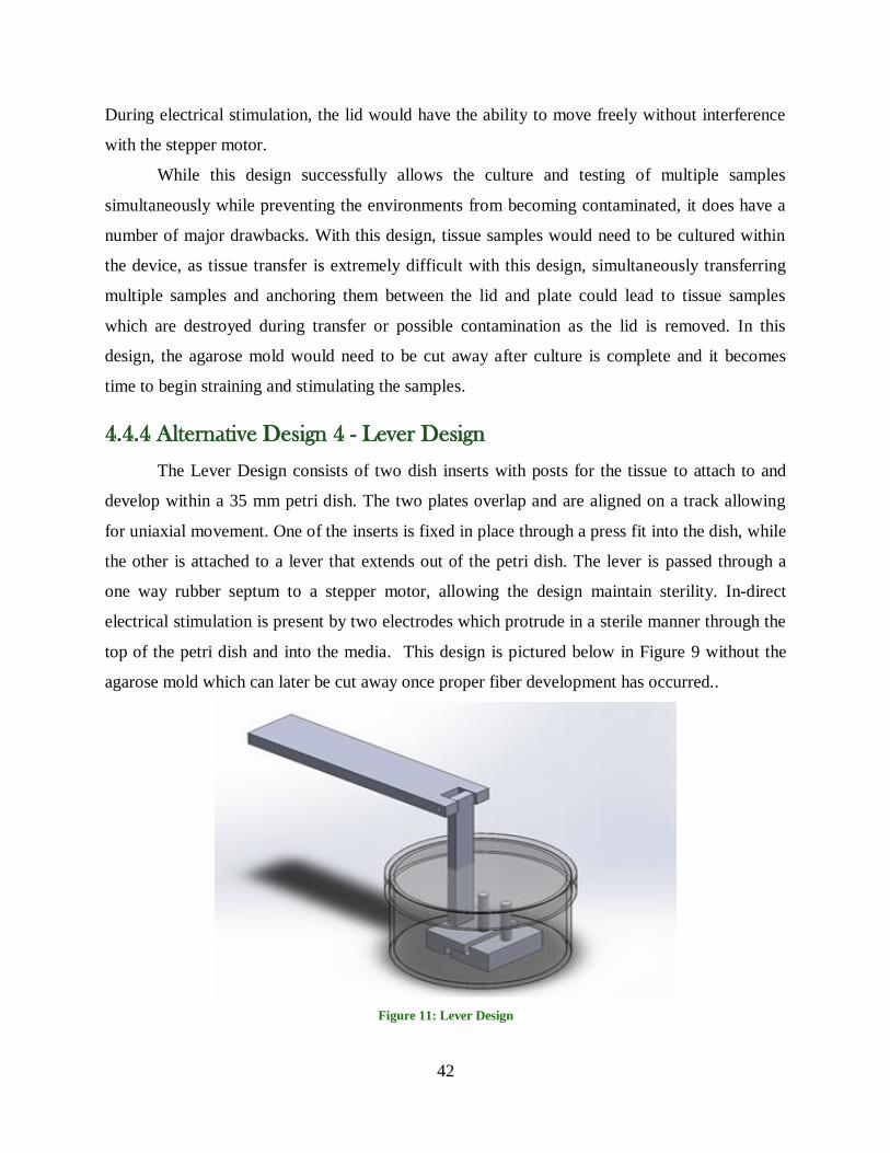
42
During electrical stimulation, the lid would have the ability to move freely without interference
with the stepper motor.
While this design successfully allows the culture and testing of multiple samples
simultaneously while preventing the environments from becoming contaminated, it does have a
number of major drawbacks. With this design, tissue samples would need to be cultured within
the device, as tissue transfer is extremely difficult with this design, simultaneously transferring
multiple samples and anchoring them between the lid and plate could lead to tissue samples
which are destroyed during transfer or possible contamination as the lid is removed. In this
design, the agarose mold would need to be cut away after culture is complete and it becomes
time to begin straining and stimulating the samples.
4.4.4 Alternative Design 4 - Lever Design
The Lever Design consists of two dish inserts with posts for the tissue to attach to and
develop within a 35 mm petri dish. The two plates overlap and are aligned on a track allowing
for uniaxial movement. One of the inserts is fixed in place through a press fit into the dish, while
the other is attached to a lever that extends out of the petri dish. The lever is passed through a
one way rubber septum to a stepper motor, allowing the design maintain sterility. In-direct
electrical stimulation is present by two electrodes which protrude in a sterile manner through the
top of the petri dish and into the media. This design is pictured below in Figure 9 without the
agarose mold which can later be cut away once proper fiber development has occurred..
Figure 11: Lever Design

43
4.5 Final Design
After creating the alternative designs the group performed a design comparison. This was
done by numerically evaluating each design in order to determine the degree to which objectives
were satisfied. The design comparison is shown below in Table 3.

44
Table 3: Design Comparison
Multiplier Objectives Magnet Lever Syringe
Pump
Moveable
lid
N/A Fits in Incubator Y Y Y Y
N/A Biocompatible/Sterilizible Y Y Y Y
N/A Safe for Tissue Y Y Y Y
4 Electrical Stimulation 2 2 2 2
4 Mechanical Stimulation 1 3 2 3
5 Sterile Enviroment 3 3 2 3
3 Measure Stress and
Strain 1 2 2 2
1 Time/Cost Effective 2 3 2 2
5 Tissue Transfer 1 3 3 1
2 Ease of use 2 3 1 2
Total 41 65 51 52
After comparing the designs and adding all the values up the lever design was picked to be our
conceptual final design. It had the highest score and satisfies all the constraints.
4.6 Feasibility Studies
In order to verify the chosen preliminary design a series of feasibility studies must be
conducted to determine various components and the optimal cell culture environment for the
design to function. These studies include the shape of the agarose mold, the co-culturing of
fibroblasts, and the post shape.
4.6.1 Co-Culturing with Fibroblasts
To create an in vitro muscle fiber that most clearly resemble an in vivo muscle fiber
fibroblasts and myoblasts must be used. The two cell types will be cultured separately and
subsequently combined to create the muscle fiber. This will be attempted to see if co-culturing
with fibroblasts is possible. This is an important consideration for tissue development because

45
fibroblasts are primarily responsible for production of the extracellular matrix that supports the
tissue. If the fibroblasts can be combined successfully with the myoblasts this technique will be
used in all testing of any designs created; if it does not work only myoblasts will be used to
create a muscle fiber.
4.6.2 Anchoring Posts and Mold Shape
The post shape of the mold and the well shape of the mold was chosen according to
feasibility studies to be performed later on in the project. These studies were intended to be done
to identify the best anchor for the muscle fiber. Several different shapes were chosen as potential
options, however it was decided that a cone shaped mold anchor, followed by a circular actuating
anchor would be the best choice. The cone shaped mold anchors are shown below, in figure 10,
provides a less dramatic transition from a round shape to a linear shape. In creating a cone-
shaped anchoring post we hope to avoid tissue necrosis at the point of intersection between the
linear and anchored regions of the tissue that may otherwise occur in tissues without such a
transition. This shape is only present in the mold, and not on the device’s posts due to
manufacturing constraints. Ideally, the cone-shaped development in the mold will allow for less
of a chance for the fiber to break upon mechanical stimulation.
Figure 12: Cone Shaped Post Design
Well shape will also be tested to determine the optimal design. A v-shaped design and a
u-shaped design were both developed to determine if there is a benefit to having a rounded or
pointed bottom. These two well designs are somewhat narrow to constrict the culture surface
area and completely direct tissue construct formation. A third mold well design was also
developed based on the presumption that the cells align during differentiation and fusion without
specific guidance. In this design, the two anchoring posts still remain but the surrounding well is
open so that the cellular behavior will dictate tissue formation. Each of these three designs will

46
be tested to determine which provides the best results for forming a cohesive tissue construct.
Conceptual models for the mold designs may be seen in figures 13 and 14 below.
Figure 14: Top View of Well Shapes
The final mold design includes the three conceptual models to be tested and may be seen
in figure 12 above. This is a double negative of the final mold we hope to create; a prototype of
the finished product, seen in figure 13 below, will be cast in polydimethylsiloxane (PDMS), the
mold of which will then be cast in agarose gel to create the final working tissue mold.
Figure 13: Front View of Well Shapes

47
Figure 15: Manufactured Mold for PDMS Casting
4.7 Preliminary Data
Before choosing a design, preliminary data was considered in order to appropriately
choose a final design. The following categories were looked at carefully while making
alternative designs. Each of these subsequent items will all need data to justify their use in this
design.
4.7.1 Cell Culture Standards
The cells seeded into our tissue mold must be able to successfully differentiate and fuse
to form muscle fibers without adhesion. For this reason, agarose was chosen as the mold for
tissue growth. Agarose can also include media and growth factors to further encourage cell
growth and differentiation.
A three-dimensional tissue construct should be able to be created and it should be able to
be transferred from mold to device without any tearing. For this reason the v shaped well was
chosen due to its believed ability to direct tissue growth better than the other two mold shapes.
Previous project work has successfully demonstrated that this works in developing a 3-D tissue
construct (Ohlson, 2011). Cells will be stained and viewed using standard immunocytochemistry
protocols to determine if they have successfully differentiated. Observing the tissue construct
under a microscope will also prove whether or not a successful 3-D construct has been
developed.

48
4.7.2 Strain Distance
This device should stretch the muscle to at least 10% strain. However, an adjustable
device would be desired in order to be able to experiment with optimal strain. Therefore, we can
observe the distance of strain with either a close up camera shot and Image J software, or by
using Calipers. If the device can successfully stretch to 10% of the original standard length we
decide on, the strain distance has been successfully developed.
4.7.3 Sterility
Cell culture and testing requires all parts involved to be sterile to prevent contamination.
Therefore, cell cultures will be grown in the device before mechanical and electrical testing in
order to ensure there is no contamination. Several of the design alternatives involve moving parts
that could potentially bring contamination into the system. However, after growing several
cultures and testing for contamination, we should know which aspects cause the design to
become contaminated or whether it can maintain a sterile environment.
This system must also be easy to sterilize so that it can be easily reused. In order to allow
for easy sterilization, it was decided that all parts must be able to be autoclave compatible.
However, in cases that this was not possible, ethylene oxide would be an acceptable form of
sterilization. Ideally, any part that would be in contact with cells would need to be sterilized in
the autoclave because in some cases, ethylene oxide can cause cell death.
4.7.4 Materials
Several different materials will be used in this design, and each potential material must be
tested for its desired use. For instance, metal electrodes must be integrated into each design in
order to electrically stimulate the muscle tissue. However, if these metals oxidize easily, they
will not be able to sustain themselves in the cell culture media. In turn, they will not be feasible
to use in the design. It is for this reason that the material and mechanical properties of each
different part are appropriate for their intended use. Not only must they accomplish their
predetermined job, but they must not cause a problem anywhere else in the design.

49
Chapter 5: Manufacturing
In order to ensure that the device was both effective in its function and easy to
manufacture, the strengths and limitations of CNC manufacturing processes were acknowledged
when conceptualizing the structure of the device. The 3-dimensional models of some
components were modified to reflect these criteria. The following explains the manufacturing
process in detail and the modifications that were made to the design along the way.
5.1 Final Design and Manufacturing Processes
The final design chosen was the stepper motor-actuated lever design. This design utilizes
a 35mm diameter petri dish, in which the tissue is cultured on the agarose mold. Inside the petri
dish, two plate-post constructs are used to mount the tissue, as well as apply strains. Although
overall design is the same, the dish insert was altered to improve the function of the entire
device. One plate will be fit to the inner diameter of the petri dish, and would not require any
external forms of fixation. In addition, the heights of the two plates are now staggered to allow
the plates to move without interference. These dish inserts can be seen in the figures below.
Figure 16: Pictured on the left is the stationary dish insert, and pictured on the left is the moving dish insert.
Other additions to the design included a base construct that has the ability to hold the
petri dish in place, as well as attach to the stepper motor. This fixation ensured that forces
applied during actuation do not cause the entire petri dish to move, but only the actuating dish
insert. This base fixture is approximately 60mm wide in each direction, and was manufactured
from a ½” thick polycarbonate sheet. This design also utilized a total of four M4 x 0.7mm

50
tapped holes. This included two holes to adjust the tightness of the petri dish fixation based on
screw tightness, and a second set of threaded holes allows for the attachment of the stepper
motor, which is approximately 54mm wide. A top view showing the placement of the tapped
holes, signified by the red dots, is displayed in Figure 10.
Figure 17: Translucent Top View of Full Design
The placement of the motor allowed for a direct connection of the stepper motor’s
actuation shaft to a lever arm via a single connection point. The lever arm will cross through the
cover of the petri dish, through a hole fit with a rubber septum. This septum will applies enough
of a holding force to hold the lever at a specified height, and will serve as the lever arm’s
fulcrum point. This lever arm will be manufactured using a lathe from polycarbonate rods, much
like the circular petri dish insert.
The last element of this design is the removable electrode system. The electrodes connect
to copper wire, which conducts currents through the system. Metal screws act as the electrodes
and will penetrate the cover of the dish. A soldering iron was used to create the holes in the dish
cover to avoid cracking. These screws were trimmed to an appropriate length and a pipette tip
was threaded onto screw on the inside cover. Platinum-iridium wire was then used as the tip of
the electrode, which will connect to the screw inside the pipette tip.
All of these parts were assembled to create our final design. The stepper motor was
purchased and polycarbonate components were manufactured using the aforementioned
processes. The manufacturing of the polycarbonate components was either performed by or
supervised by appropriately trained manufacturing students, depending upon whether the use of
the lathe or mill is required, respectively. The final design appeared as the model developed in
Solidworks. An isometric view of this model is viewable in Figure 2, below.

51
Figure 18: Model of Complete Design
5.2 Material Choices
As previously stated, the final design is composed of multiple components in order to
accomplish the desired product. The working parts include a stepper motor for mechanical
actuation, platinum and copper wire for electrical stimulation, medical adhesive, septums, and
polycarbonate to make the device. Table 4, shown below, is our bill of materials thus far with the
specifications, price, and amount.
Table 4: Bill of Materials
Specifications Amount Price Ordered From: Stepper Motor 29 oz. (200 steps/rev,
threaded shaft) 1 29.95 Sparkfun
Platinum Wire 99.95% platinum 3ft 140.54 Tritech research Easy Driver N/A 1 28.07 Sparkfun
Precision Seal Rubber
Septum 7mm O.D. 10 12.90 Sigma Aldrich
Polycarbonate rod and sheet 10 ft 1 40 McMaster
Screws M3 .05 40mm length
Metric Pan Head Phillip
Drive
100 14.22 Amazon
This particular stepper motor was chosen because it is made for linear actuation and has
200 steps per revolution. Because of these specifications, it is very precise and accurate, and can
be used for micromotion in the dimensions needed. This is advantageous for our device because
our 5mm tissue will only be strained 10%, for a total of only 0.5mm. The platinum was chosen
because it is a great conductor and has a higher resistance to corrosion than other metals.
Because it is a very pure alloy, 99.95% platinum, it can produce a better electric field. A strong

52
and consistent electric field is important because the electrodes are stimulating the media, which
will become our electric field. The media needs to have consistent current and voltage
throughout in order to ensure the field reaches the tissue evenly and symmetrically. Silicone glue
was deemed necessary to seal the electrode screws to prevent contamination, while still being
able to be sterilized. It is inexpensive and able to be autoclaved, making it the perfect choice. The
Precision Seal Rubber Septum will be put in the top the petri dish the actuation hinge goes
through in order to keep everything sterile. This particular septum was chosen because it is low
cost and does not touch the muscle or media and therefore can be sterilized using ethylene oxide.
Finally, polycarbonate was the material of choice for most of the device because it can also be
autoclaved, it is low cost, and easy to manufacture.
5.3 Stepper Motor Modification
The chosen stepper motor was selected primarily for its ability to actuate linearly as it
rotates, allowing for accurate and controllable movement through a controller. To ensure that the
motion created by the motor is applied with precision, the motor was modified to enable it to be
fixed to a stainless steel back plate. The modification to the motor involved removing the four
screws around its perimeter, and replacing the original screws with longer M3 screws with the
same pitch. Removing the threads within the motor’s face will prevent cross threading and
misalignment when fixated to the threaded back plate. This process was completed by hand with
a battery-powered drill.

53
Figure 19: Stepper Motor Modification
5.3.1 Back Plate
Stainless steel was chosen as the material for the back plate of the device due to its ability
to resist deflection, and therefore prevent any unwanted micro-motion. To manufacture this
component, the stainless steel stock was cut to the desired width of the device, and to a height
that would ensure that the motor’s actuation remained at an appropriate height above the dish.
Next a series of holes were drilled into the plate which included two loose-fitting M5 through-
holes, four evenly spaced, tapped M3 holes, and a central hole to allow the passage of the
actuating shaft. A HAAS vertical mini-mill was chosen to create this component, guided by
code generated using Esprit.
Figure 20: Stainless Steel Back Plate
5.4 Base
The base design involves two manufactured components which were created from 6” x
6” x ½” polycarbonate stock. The purpose of the base is to fixate the petri dish in place, and
ensure it does not move while the motor is in use. Additionally, the base utilizes an interference-
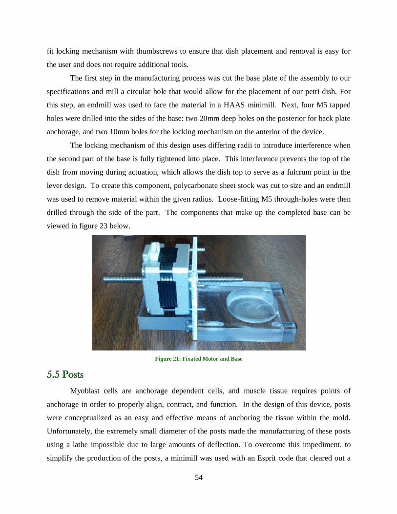
54
fit locking mechanism with thumbscrews to ensure that dish placement and removal is easy for
the user and does not require additional tools.
The first step in the manufacturing process was cut the base plate of the assembly to our
specifications and mill a circular hole that would allow for the placement of our petri dish. For
this step, an endmill was used to face the material in a HAAS minimill. Next, four M5 tapped
holes were drilled into the sides of the base: two 20mm deep holes on the posterior for back plate
anchorage, and two 10mm holes for the locking mechanism on the anterior of the device.
The locking mechanism of this design uses differing radii to introduce interference when
the second part of the base is fully tightened into place. This interference prevents the top of the
dish from moving during actuation, which allows the dish top to serve as a fulcrum point in the
lever design. To create this component, polycarbonate sheet stock was cut to size and an endmill
was used to remove material within the given radius. Loose-fitting M5 through-holes were then
drilled through the side of the part. The components that make up the completed base can be
viewed in figure 23 below.
Figure 21: Fixated Motor and Base
5.5 Posts
Myoblast cells are anchorage dependent cells, and muscle tissue requires points of
anchorage in order to properly align, contract, and function. In the design of this device, posts
were conceptualized as an easy and effective means of anchoring the tissue within the mold.
Unfortunately, the extremely small diameter of the posts made the manufacturing of these posts
using a lathe impossible due to large amounts of deflection. To overcome this impediment, to
simplify the production of the posts, a minimill was used with an Esprit code that cleared out a

55
circular channel. The process left 1mm section of material intact in the center of the cut, acting
as the tissue posts. Posts can be easily removed from the polycarbonate stock using hemostats
and trimmed to the proper height. These posts were then press-fit into the holes on the sliding
dish inserts.
Figure 22: Anchoring Post Production Method
5.6 Dish Inserts
The next step was the creation of the stationary and actuating dish inserts, described in
Section 5.1. The stationary insert was created from a 2.5”polycarbonate rod stock, and was first
placed in a lathe. Using the lathe, the diameter of the rod was reduced to tightly fit within the
petri dish, and then cut to a height to allow the piece to be well gripped and further modified in a
minimill. In the minimill, two main cuts were made. First, an endmill was used to face the
bottom of the component to create the channel that served as an actuating track for the moving
insert. Next, the part was repositioned and the endmill was used again to make the second cut
and create the plate’s “U shape”. A smaller diameter tool was used, in addition to a smaller
cutting depth for each interval.
In order to ensure that the polycarbonate inserts do not interfere with the hanging
electrodes, two additional holes were drilled vertically through the sides of the insert. These
holes will create small wells to be filled with media and allow for the tips of the electrodes to be
completely submerged and bring current to the tissue sample.
The second movable dish insert was also created using a HAAS minimill. A small
endmill was used to cut the stock to size, and to create the center channel of the plate. This
center channel was created to allow for space for the rubber insert to fit without dragging along
the bottom of the disk, and to reduce the surface area in contact between the part and the bottom
of the dish. Two holes were drilled into the actuating plate, a 4mm diameter hole for the rubber
insert, and a .0040” hole, which will be used to press-fit the 1mm posts.

56
Figure 23: Fully Assembled Dish Inserts with Posts
5.7 Dish Cover Modifications
To enable entry points for both mechanical and electrical stimulation, the cover of the
petri dish was modified. Using a Bunsen burner, metal pieces of 6mm and 2mm diameter were
heated and used to create the septum hole and electrode holes, respectively. A 7mm septum was
press fit into its respective hole and trimmed of excess rubber, and two screws were placed
through the electrode holes. These components were then adhered to their positions using
silicone adhesive that preserved the enclosed sterile environment during use. Finally, the tip of a
100mL syringe needle was used as a lever and was placed through the septum and into the
rubber component of the actuating dish insert.

57
Figure 24: Modified Dish Cover and Full Dish Assembly
5.8 Electrodes
The intent for the design of the electrodes involved keeping them modular, for
sterilization purposes, while also ensuring strong connection between the power source and the
electrode tip. A screw, which penetrates the dish cover, is the connection point for the power
source as well as the electrode itself, and carries the current into the dish. The modular section
of the electrode tip was created by crossing a small platinum piece of wire with copper wire of
similar diameter, and winding the platinum wire around itself until secure. Copper was wound
within the inner diameter of a pipette tip cut to size. Screws were then used to coax the copper
wire into a helical shape. A small amount of silicone adhesive was added within the pipette tip
to hold the assembly in place without permanently attaching the tip to the screw.

58
Figure 25: Electrode Assembly Diagram
5.9 Lever-Motor Connection
The final component necessary in ensuring that the linear motion created by the stepper
motor effective reaches the tissue is the connection between the lever and the actuating shaft. A
modified 22-gauge needle was used as the actuating arm and was connected to the motor drive
shaft using two washers. The washers were screwed onto the shaft and the top portion of the
needle was fitted in place securely between the two. The rear washer, closer on the shaft to the
motor itself, was fixed in place on the shaft using a silicone adhesive. The full assembly may be
seen in Figure 28.
Figure 26: Full Mechanical Actuation Assembly

59
Chapter 6: Motor Wiring and Programming
A mechanism of mechanical actuation for the tissue constructs was implemented into the system
and driven via a linear actuating stepper motor. This motor was connected to an EasyDriver
Stepper Motor, which was then powered and controlled by a connection with an Arduino Uno
microcontroller. The motor was connected to a twelve volt power supply from the EasyDriver,
which itself was wired to a five volt power supply. The wiring diagram for the stepper motor
may be seen in Figure 28 below.
Figure 27: Motor WIring Diagram (Stepping Up to the Challenge, 2013).
The motor system was controlled and powered by the Arduino Uno microcontroller. The
controller had both an AC output for power and a USB output to allow for connection to a
computer. Arduino uses a very simple coding language to program its systems; this allowed for
parameters that could be easily tailored according to the needs of project, and as such the amount
and rate of strain were easy to control and modify. Coding instructions for the microcontroller
may be found in Appendix G.

60
Chapter 7: Methodology
The following section outlines progress made for our MQP project. We have worked to
finalize our design, choose appropriate materials, conduct preliminary cell culture work, and
conduct testing procedures
7.1 Preliminary Muscle Cell Culture
For the purposes of growing and forming the mature muscle tissue, the C2C12 cell line
was used. This is an immortalized mouse myoblast cell line that serves as progenitors to the
mature muscle cells. These cells may be maintained in an undifferentiated state or induced to
enter terminal differentiation and form mature muscle cells based on the culture medium and
treatment conditions used. Further details and step-by-step explanations of each cell culture
procedure are provided in Appendix D.
7.1.1 Cell Culture
Cells must be cultured in a liquid culture medium in order to survive and remain viable.
Culture medium contains the metabolites, proteins, growth factors, and nutrients cells need to
live; it is also made at a pH of 7.4, and typically contains an indicator that causes the color of the
medium to change as the pH level changes. As cells undergo replication and other normal
processes, they will take in these nutrients and proteins from the medium and release waste
products, causing a change in the pH. Medium in the normal pH range will appear red but as the
cellular processes persist over time the medium tends to become more acidic and thus takes on a
yellow hue.
Many different supplements may be added to the culture medium as well to elicit
different cellular behaviors. Common examples of these supplements include glutamine, animal
serum, and penicillin/streptomycin. Glutamine is an amino acid that improves the growth and
performance of cells. Animal serum, commonly fetal bovine serum, is the plasma portion of
blood from the source animal that remains after coagulation has occurred following death. Fetal
bovine serum contains many different growth factors that are very beneficial in cell proliferation.
Another commonly used serum is horse serum; in this instance, the serum is derived from the
adult animal and thus contains proteins more tailored to this mature organism that may direct
progenitor or stem cells to differentiate. While animal sera are very beneficial in culture work,

61
there are numerous ethical issues associated with their use, which have lead to the development
of synthetic substitutes to serve in the same applications. Penicillin/streptomycin, commonly
abbreviated as pen-strep, is an antibiotic that fights infection by foreign contaminants that may
be accidentally introduced during culture work. Pen-strep is not always included as a
supplement to culture medium as it tends to mask but not eliminate bacterial contaminants, but it
may be included in such circumstances as when the researcher is less experienced or when the
lab space is shared by multiple groups and the potential for accidents is increased.
For the purpose of long-term storage, cultured cells may be held indefinitely in liquid
nitrogen for cryopreservation. To begin working with these cells, they must be removed from
liquid nitrogen storage and thawed. Cell thawing is a fairly rapid procedure that begins when
cells are transferred from liquid nitrogen to a water bath maintained at 37 °C. The cryovial is
submerged in the water bath for approximately one to two minutes, until there is only a small
crystal of frozen suspension remaining. It is then rapidly transferred to the culture hood and
combined with the normal culture medium. This suspension is then centrifuged to isolate the cell
pellet and then re-suspended in a new volume of medium before being added to culture flasks
and incubated.
Once the cells have been added and supplemented with the necessary volume of medium
(10 ml total volume in a 75 cm2 flask is the standard for this work), they are moved to an
incubator set to optimal growth conditions. Mammalian cell culture incubators are set to a
temperature of 37 °C with a 5% carbon dioxide concentration in the ambient air and between 90
and 100% humidity. To preserve the cells in an undifferentiated state of proliferation, the
standard proliferation medium used consists of a 60:40 (by volume) ratio of Dulbecco’s
Modified Eagle Medium to Ham’s F12 medium supplemented with 10% FCIII (a fetal bovine
serum substitute) and 1% Glutamax (a glutamine substitute). When terminal differentiation and
mature muscle formation is sought, the choice of medium is changed to a differentiation
medium. This consists of a 60:40 (by volume) ratio of DMEM to F12, supplemented with 2%
horse serum, 1% Glutamax, and 1% insulin-transferrin-selenium, an additive that works in a
similar manner to and bolsters the effects of the horse serum.
If allowed to become overly confluent, C2C12 cells will exhibit signs of contact
inhibition and may begin to differentiate. This is due to the fact that when cells do begin to
contact each other they will arrest proliferation. To circumvent this issue, cells must be passaged

62
and added at lower seeding densities to new culture vessels to maintain their integrity. Many
lines of cultured cells, including C2C12 cells, will adhere to the bottom of the culture vessel as a
result of protein interactions between the cell and dish surface. Thus, the first step in passaging
requires breaking apart these interactions and removing the cells from this adherent state. The
culture medium is removed and trypsin, a protease, is added for a short period of time to disrupt
these protein interactions. Culture medium is then added back to the dish as the animal serum
contains protease inhibitors that will stop further destructive actions of trypsin. The suspension
is then transferred to a centrifuge tube and centrifuged to isolate the cell pellet. Old medium is
removed and new medium is added to the pellet to re-suspend the cells, a count is conducted to
approximate the total number of cells present within the suspension, and the cells are added to
new culture plates and incubated. These cells should be cultured to no more than 60-70%
confluence before being passaged and added to new plates at lower seeding densities.
When it is desired for stocks of cells to be frozen for later use, similar steps are followed
as for the passaging procedure. However, once the cell count is determined, an appropriate
number of cells is instead moved to a freezing medium stock. This medium consists of DMEM
supplemented with 20% dimethylsulfoxide, a cryoprotectant that prevents cell death during
freezing, and 10% FCIII. The suspension is added to the cryovial, placed into an insulating
freezing container, and moved to a -80 °C freezer. In contrast to the thawing process for cells,
freezing is a slow procedure in which the cells are expected to cool to frozen very gradually so
they are not damaged by shock from the cold. After spending roughly 24-48 hours in the -80 °C
freezer, cells will typically be transferred directly to liquid nitrogen storage for indefinite
preservation; however they may be held in this -80 °C freezer for several months without issue.
7.2 Mold Creation and Validation
An integral part of the device being able to function as it is intended is proper muscle
fiber development. After the time spent developing the mold shape, the mold was created and
tested to assure that it would function as designed.
7.2.1 ABS Plastic Mold
In order to produce our mold in a sterile, but also cost effective manner, we decided to
first make a negative mold out of an inexpensive plastic material. Originally, our team decided to
use the 3-D printer in Higgins Labs at Worcester Polytechnic Institute because it is an easy

63
machine to use with a quick manufacturing turnaround. Once the design was submitted and the
product was received, we observed the mold under a microscope. Unfortunately, the 3-D printer
had very low definition that created visible cavities in the mold. These cavities presented a
problem because the PDMS mold, once poured, would adapt this same texture, eventually
transferring it to the agarose mold as well.
ABS plastic was the next option explored. This mold was created with the objet machine
located in the same Higgins manufacturing facility. The first mold created had well walls that
were extremely steep, hoping that steep wells would be better for fiber formation. Because of the
extremely small size, the posts on the mold could not be manufactured without breaking.
Therefore, it was decided to decrease the pitch of the walls in order to aid in the manufacturing
process. A glossy finish was also chosen to allow for easier removal of the PDMS by decreasing
the surface roughness of the mold. This final mold can be seen in the figure below.
7.2.2 PDMS Mold Process
Upon receiving the third mold, the PDMS positive mold could be created. After several
trial runs, it was found that 5 grams of elastomer base to 0.7grams of curing agent created a
flexible but structurally sound mold that would be able to model the correct shape for the
agarose. The mixture was combined in a 35mm petri dish and thoroughly mixed for at least 2
minutes. Once the composition was completely combined, the ABS plastic mold was added to
the mixture and completely submerged. All bubbles created from mixing were removed through
a 20 minute vacuum chamber. The petri dish and mold submerged in PDMS solution was then
placed to cure in a 60°C oven for one hour. After the hour, the PDMS was checked to make sure
it was solid, and then removed from the oven.
Figure 28: ABS Plastic Double Negative Mold

64
To remove the PDMS mold from the ABS mold, excess PDMS was cut away slowly with
a scalpel around the ABS mold. Once the excess was removed, the PDMS was very slowly
peeled from the mold. This was a slow and careful process to ensure all details were preserved.
Finally, once the mold was completely peeled away from the ABS plastic, the PDMS mold was
sterilized by autoclave in order to prepare it for sterile agarose mold production.
7.2.3 – Agarose Mold Construction
The agarose mold that was needed to guide fiber development needed to be constructed
in a sterile manner in order to ensure the cells were not contaminated. To do this, the already
autoclaved PDMS mold, along with a sterilized wall to surround the mold was placed into a
sterile hood along with sterile petri dishes, sterile pipettes, and sterile forceps.
Sterile 2% agarose solution was created by adding 1gram of agarose powder to 50mL of
DMEM solution. It was important that simply the base solution of DMEM was used without any
extra serum because this could potentially cause adverse reactions with the agarose powder.
Once the mixture was added to the media, the bottle containing the mixture was sealed. The top
was not completely screwed on to ensure that when autoclaved, it would not get stuck shut.
Autoclave tape was used to mark the bottle, and the bottle of media and agarose was autoclaved
for 30 minutes to boil the solution in a sterile manner.
Once the autoclave cycle was complete, the bottle was transferred to the sterile hood. The
wall to surround the mold was installed with sterile forceps, and the gel was pipetted into the
mold. About 800-900 mL of the solution was pipetted into the mold to achieve the desired
thickness. After the gel was solid, it was removed by pushing the bottom of the PDMS from the
wall surrounding the gel and slowly separating the PDMS and the agarose. The agarose mold
was then placed in a sterile petri dish, labeled, and set aside for later experimentation. This
process was repeated several times to create multiple molds.
7.3 Proof of Concept Testing
Before cell seeding and final validation, the individual functions of the device were tested
and validated to ensure proper function.

65
7.3.1 Mechanical Proof of Concept
The mechanical actuation system that was developed to provide for uniaxial linear strain
in the tissue involved a stepper motor driving an actuating lever arm that attached to one of the
two dish inserts within the stepper motor. The lever was attached to the moving insert, which
was capable of moving along one axis within the tracks of the larger fixed dish insert. Two
tissue anchoring posts were included in this setup, with one post on each dish that would hold the
tissue in place. These posts served to sustain the tension that the tissue exerted during
development and later allowed for actuation as a means of mechanical stimulation. In order for
this system to be validated it was necessary to confirm that the polycarbonate tissue posts were
capable of sustaining the tissue’s tension and that the motor could successfully be used to actuate
this system with a tissue construct anchored to it. This was done by wrapping a dental
orthodontic rubber band around the two anchoring posts, and observing the effects in the petri
dish
7.3.2 Electrical Proof of Concept Testing
To validate the electrical stimulation of our device, media was put into the petri dish and
the electrodes were hooked up to an electrical source, the Agilent 33220A. It was set at a
frequency of 7 Hz and amplitude of 10 volts. To make sure the correct electrical signal was being
sent, the leads from the Algilent 332200A were connected to an oscilloscope and the correct
signal was verified. The leads were then attached to the electrodes and the media began to
bubble, thus verifying that an electrical field was created within the media. Below is a figure
demonstrating our experimental process.

66
Figure 29: Electrical Stimulation Proof of Concept Testing
7.4 3D Tissue Construct Development
Once the culture techniques had been verified in 2D culture, the team was ready to
attempt to seed cells into the agarose mold to test for tissue formation and prepare for stimulation
of the mature construct. Preparation for seeding was done by changing the cell culture medium
in both the C2C12 myoblast cells and the CRL 2097 fibroblast cells to differentiation medium
approximately twenty-four hours prior to seeding. This allowed the cells being used to begin
adapting to the new growth factors and exit the cell cycle before seeding began so that
differentiation and tissue formation could begin as soon as the cells were seeded together.
At the point of cell seeding twenty-four hours later, the tissue mold was placed on top of
the dish inserts, all of which was completed inside the 35mm petri dish. The mold was then
flooded with cell differentiation medium and incubated for a period of at least fifteen minutes in
order to condition the environment for the introduction of cells. Cells should then be trypsinized
and counted to allow for proper seeding densities. Recommendations from a department
graduate student stated that the fibroblast seeding density should be 25% of the myoblast seeding
density, and this value was used as a baseline. The utilized myoblast seeding count was one
million cells and the fibroblasts in turn were seeded at an approximate density of 250,000 cells.
The total volume held within the channel was measured at 20ml. It was important to consider
uniform seeding across the entire mold, and so an effort was made during seeding to evenly
distribute the cell suspension as evenly as possible between the central linear region of the mold
and the circular regions surrounding the tissue anchoring posts.

67
Chapter 8: Testing and Validation
The final design required testing following assembly to ensure that the system was in
workin order and could accomplish the establish goals of the project. This was first
accomplished by testing each of the individual components of the system before finally
attempting to operate the entire system in unison.
8.1 Mechanical Stimulation Proof of Concept
By wrapping a dental orthotic rubber band around the two anchoring posts and powering
the motor, it was proven that the system was capable of operating properly and actuating the
elastic band. The device functioned as designed, fully actuating it outwards and then back
inwards at a controlled pace. As intended, the posts proved to be slightly flexible so that they
could give with the contractile stresses in the muscle tissue construct, but did not break due to
these stresses.
8.2 Electrical Stimulation Proof of Concept
After preforming the aforementioned electrical validation procedure, the electrical current
was not only read successfully through the oscilloscope, but it was also successfully producing
small bubbles in the media due to the electrolytes present in solution. This proved that electrical
current was passing through the device, and that the electric field would be propagated to the
cells once seeded in the assembly.
8.3 Sterilization
Sterilization of all components and maintaining a sterile environment for the cells is a key
concern in conducting cell culture work. Using a rubber septum as an interface between the
internal environment of the culture vessel and the external surroundings and system components
allowed for maintenance of this sterile environment. The needle that served as the actuating
lever arm was the only component that bridged the two sides. This needle was sterilized with
ethylene oxide treatment prior to introduction into the system and held separately and sterilely
until it was used. Following introduction through the septum in remained in place as much as
was possible or was thoroughly re-sterilized if removal became necessary.

68
The remaining components of the system were similarly treated with ethylene oxide
sterilization prior to use to ensure their sterility. The system was assembled in a largely aseptic
manner and it was thus essential that the components be sterilized once built. Polycarbonate,
which was used for the dish insert material, is able to be autoclaved safely, however several other
components of the system, namely the polystyrene cell culture petri dish, may not be subjected to
such high temperatures safely and thus all components were sterilized under ethylene oxide
treatment. For subsequent trials after initial sterilization, the components were soaked in 70%
isopropyl alcohol and subjected to UV light exposure for several hours following extensive
rinsing with sterile PBS to sterilize.
Penicillin/streptomycin is a commonly used antibacterial reagent in cell culture work to
prevent contamination. It is generally avoided if possible, however, because of a number of
known problems associated with its use. Pen/strep is generally known to mask the presence of
bacterial contaminants present at low concentrations and it further may induce the development
of antibacterial-resistant strains of bacteria. That being said, in the context of this project it
became necessary to use pen/strep to ensure that results were obtained. Working in high-volume
lab spaces such as the lab available to the team and working under time constraints where
contamination may seriously mar the end results mandated the use of pen/strep, at a
concentration of 1% by volume, within the culture medium.
8.4 Bromodeoxyuridine Staining for Cell Proliferation
As was previously mentioned, the C2C12 muscle cells are cultured in proliferation
medium for continued growth and transferred to differentiation medium for terminal
differentiation and fusion to occur. The different behaviors of the cells under varying treatments
may be visualized and quantified using bromodeoxyuridine. BrdU is a thymidine analogue
nucleoside that will incorporate itself into cellular DNA during the S phase of the cell cycle, and
therefore may be used to mark cells that are undergoing division. Fluorescently tagged
antibodies may then be used to target the cells containing BrdU, allowing for imaging under a
fluorescent microscope. A full procedure for BrdU staining may be seen in Appendix F.
An equal number of cells were added to 6-well plates in three replicates of proliferation
and differentiation medium. Last year’s project team confirmed that 2% horse serum
supplementation in the medium provided for optimal differentiation (Aschettino et. al., 2012),

69
therefore all three differentiation wells made use of this concentration in the medium. BrdU was
added to the wells approximately fifteen hours prior to analysis. At the fifteen hour time point,
the cells were fixated in methanol to prepare for staining. They were then permeabilized with
hydrochloric acid to allow for the subsequent penetration and binding of antibodies. The
primary antibody, raised against BrdU, was added to the wells and incubated to allow for binding
to the cells that had previously incorporated BrdU. Fluorescently-tagged secondary antibodies
raised against the isotype of the primary antibody were then added to stain these same cells.
Finally, cells were counterstained with Hoechst 33342 dye, a blue fluorescent dye that tags
cellular DNA and marks all cells in culture.
Immunocytochemical analysis of cells cultured in proliferation medium may be seen in
Figure 18 below.
Figure 30: BrdU Staining of C2C12 Cells Cultured in Proliferation Medium
Similar ICC analysis of cells cultured in differentiation medium is seen in Figure 19.

70
Figure 31: BrdU Staining of C2C12 Cells Cultured in Differentiation Medium
As the images above show, the cells cultured in the proliferation medium demonstrated almost
complete uptake of BrdU, marked with the green dye. Cells cultured in the differentiation
medium showed little to no uptake (the deeper and more intense green seen in the second image
is due to overexposure of the plate by the camera, as no BrdU was detected in the image at
baseline).
When viewed under phase contrast microscopy, these same images showed striking
differences between the two sets of cells as well. Proliferating cells were more isolated and
spread out across the plate, whereas differentiating cells had already begun to join together in
preparation for fusion. Representative images of these phenomena may be seen below in Figure
20.
Figure 32: Phase Contrast Microscopy of Proliferating (left) and Differentiating (right) C2C12 cells
While this assay was mostly in line with the expected results, it was not without error. A
number of cells in specific regions of two of the wells showed a fair amount of BrdU uptake.

71
This result may be accounted for in that, due to time constraints, the cells were only introduced
to differentiation medium roughly twelve hours prior to the addition of BrdU. This would not
necessarily allow for all of the cells to respond to the new proteins and growth factors and enter a
phase of terminal differentiation, and it is instead likely that some of the cells in the population
were still within the cell cycle when BrdU was added. Nonetheless, if given more time, it is
fully expected that there would be a complete correlation for cells in proliferation medium
incorporating BrdU as well as no BrdU uptake in differentiating cells.
8.4 Cell Seeding in Agarose Tissue Mold
Moderate tissue formation was seen after approximately four to five days in the agarose
mold. However, it is at this point that the team encountered the largest issue in its design. The
agarose mold could not easily be removed from the dish as intended without damaging or losing
the tissue that it had previously been supporting. Several attempts at this proved unsuccessful
and, due to the time constraints of this project, redesigns could not be completed to attempt to
improve the design and allow for a fully operational system.
Figure 33: Tissue in Dish 12h After Seeding

72
Chapter 9: Project Impact
9.1 Manufacturing
Modeling the entire system in a computer aided design software program was the first
step toward producing a final working product. Solidworks 2012 was utilized for this means.
Each individual component of the system was modeled in this program separately and then
combined to form an assembly, which was seen previously in figure 17. The base component for
which we designed around was the 35mm petri dish, and the remaining parts were built to house
and fit around this dish. Solidworks allows for a fairly simple method of developing and
accurately modifying dimensions and tolerances in components and also permits these geometric
models to be exported as files for manufacturing.
The base material for manufacturing was polycarbonate, which is a rather inexpensive
material that is easy to work with. Using only the resources available to the team on campus, the
dish inserts and petri dish base plate were able to be manufactured exactly to specification.
The stainless steel plate to support the stepper motor was also manufactured using the on-campus
resources.
9.2 Sustainability
Certain considerations were input into the design process of this system in an attempt to
limit the environmental impact of its manufacture and use. This is a common consideration that
engineers must make in product development as conservation of resources is both cost-effective
and important to a cleaner future. For purposes of sustainability, this device was designed to
operate within a 35mm petri dish. In using such a small dish size, cell culture media and
reagents were spared as larger sized dishes require several milliliters more media to completely
fill. All of the individual components were designed to be reusable. The wires associated with
the electrode design may need to be replaced after numerous uses due to the potential for
corrosion, though a limited number of resources were used for this and so the waste level is low.
Further, a platinum tip was chosen to extend from the plastic electrode casing into the media as
the only metallic component in contact with this liquid; culture medium is rich in electrolytes

73
and so a non-corrosive material such as platinum is able to withstand this environment well and
corrosive byproducts are not expected to be overly present.
9.3 Economics
Biological and biomedical research tends to be quite expensive. In 2012 alone, $124
million was spent by the NIH on research surrounding various forms of muscular dystrophy;
$4.4 billion was spent on bioengineering and regenerative medicine research; and $14.2 billion
was spent on clinical research and trials (cumulatively, extending across many more areas of
research than musculoskeletal disorders) (Estimates of Funding, 2013). A major contributor to
this number is the need for a platform of testing for various proposed therapies. In the bench-top
setting, 2D monolayer cultures as well as 3D cultures developed within scaffolds may be used to
conduct preliminary testing on these therapeutic efforts at muscle regeneration. However,
neither of these platforms are a very close approximation of natural muscle tissue, therefore
extensive in vivo testing must be conducted to thoroughly validate the efficacy of these
treatments. In developing an accurate and reproducible model of skeletal muscle tissue the need
for animal and human testing is somewhat reduced and overall project spending could therefore
be decreased. This project does offer the potential to provide this platform in the future.
9.4 Ethics
The cell culture work in this project utilized animal serums within the culture media for
the growth factors they contain. This is sure to raise some ethical concerns due to the manner in
which the sera are obtained. However, the grand scope of this project is to aim for the
development of a product that will ultimately reduce the number of animals and humans required
as testing platforms for clinical therapies. Thus the benefits of a successful device are likely to
far outweigh the ethical costs associated herein.
9.5 Health & Safety
Conducting in vitro testing of proposed clinical therapies permits determination of the
safety of this therapy prior to introduction into human or animal subjects. These subjects are
thereafter put at less risk of injury or illness as a result of treatments at the trial phase. A
determination of functionality may be studied on an in-depth basis through real-time analysis of

74
their effects on the tissue. It is hopeful that this could provide as well for a quicker output of
drugs and treatments that could save numerous lives once on the market.

75
Chapter 10: Discussion
The system described in this project report met a number of the established goals on an
individual basis. However, there were a number of design shortcomings that ultimately did not
allow the system to work as well as intended on a full scale. Nonetheless there are a number of
implications toward future works in skeletal muscle tissue engineering associated with this
project.
10.1 Stimulation Mechanisms
Proof of concept testing on the mechanical and electrical stimulation mechanisms
independently verified that the two systems worked as intended. Each could be easily
programmed and modified according to the individual needs of the product, and each mechanism
could be carried out in a manner that preserved the sterility of the system.
When skeletal muscle cells begin to fuse and develop tissue constructs, contractions will
begin sporadically as the tissue contracts upon itself. Should the anchoring posts not have been
able to flex under this tension while continuing to hold the tissue in place, the tissue would
rupture. Fortunately, the polycarbonate posts that were used in the system were proven
sufficiently flexible to sustain this tension and maintain the tissue integrity during formation.
Validation tests further illustrated that the motor would later have the ability to successfully
apply strain to the tissue; given the 5mm length of the central linear region of the tissue mold, the
goal of 10% strain was demonstrated to be possible within this system as the proof of concept
test that was run using an elastic band reached strains greater than 0.5mm, the target level. This
was unfortunately not confirmed with a mature tissue construct as the tissue did not survive to
this point but assuming revisions to the design were made to better facilitate this aspect of the
project it is anticipated that this would be possible.
Using a previous MQP report (Dao et. al., 2012) as the basis for our own design,
electrodes were designed that could be integrated into this design and emit electric pulses to the
tissue in a manner mimicking motor neuron function. Cell culture medium is a liquid rich in
electrolytes, which means that it will conduct electricity well. Therefore, the electrodes were
aligned perpendicular to the tissue to generate the electric field through the petri dish. This

76
system was demonstrated effective in practice, as electric pulses were demonstrated to be
conducted through the medium. This was again not able to be verified in tissues but it is
estimated that it would continue to work as designed in final practice.
10.2 Tissue Formation
Agarose was chosen as the hydrogel material to be used as the tissue mold for a number
of reasons. It is first and foremost a biocompatible material and will thus interact well with the
cells. Further, the cells do not adhere to the surface of the gel, which is an important
consideration. When cultured in standard petri dishes, proteins facilitate contact between the
cells and the polystyrene dish and the cells adhere, forming a monolayer; the cells are then able
to migrate about the dish surface but do not detach and cannot form three-dimensional constructs
in this manner. Using a non-adherent surface with a defined channel shape directs the cells to
fuse with each other and in the shape provided by the mold channel.
Roughly four to five days after the cells were seeded into the mold channel, there was
moderate tissue formation witnessed. Utilizing a co-culture system, the fibroblasts would be
able to generate supporting extracellular matrix proteins as the myoblasts fused to form tissue. It
was at this point however that the device’s greatest shortcoming was elucidated, however.
Whereas the design was developed with the vision that the tissue mold could be fairly easily cut
away using a sterile scalpel, this did not prove possible, at least within our means, without
damaging the tissue or pulling it away and losing it along with the extracted mold. It is also a
distinct possibility that the tissue was simply not provided with enough time to mature into one
unified construct and that further time was required for development of the tissue so that it would
be sufficiently strong to withstand the process of gel extraction.
10.3 Overall Design
Several issues were encountered in testing and validation of this tissue engineering
system that precluded the successful attainment of all goals. As previously referenced, the
greatest issue that the team was not able to overcome was the proposed method of removing the
agarose tissue mold from the petri dish and leaving the tissue intact, which was proven
unsuccessful in multiple attempts. Another factor that may well have contributed to this was the
size of the petri dish. Previous MQP projects attempting to approach the same topic utilized
100mm petri dishes (Aschettino et. al., 2012). It was indicated that the consumption of resources

77
in this design was high and that a smaller dish could be used. Given the scope of this project and
the sought-after development of a tissue 5mm in length, 35mm was a viable option for the size of
our petri dish. However, this limited to some extent the ease with which the system could be
manipulated. It also left very little clearance between the top of the mold and the underside of
the petri dish lid, which made submerging all of the components of the dish challenging.
The connection point between the motor shaft and the lever arm proved sufficient for our
purposes, but could have been improved upon. The mechanism of locking the lever in place
consisted of two washers fitted firmly on each side of the lever top at the point it contacted the
motor shaft. Given that this was a threaded shaft the options for connection mechanisms were
limited, though this could have been explored more in depth to determine alternative means.
In order to incorporate the mechanical and electrical systems into the petri dish, holes
were placed in the petri dish top. The parts were placed in the lid and then sealed using silicone
adhesive. The presence of all of these components as well as the sealing adhesive material
utilized much of the central lid space and it thus became difficult to conduct full analysis of the
forming tissue using microscopy. For this reason the cells were generally cultured using a
normal lid before changing to the sterile modified lid after several days in preparation for
stimulation.

78
Chapter 11: Recommendations and Conclusions
Certain successes were seen within each of the individual components of this system,
being the tissue mold system, the mechanical actuation system, and the electrical stimulation
system. Based upon observations of some of the limitations and how they could have been
overcome, the team has developed several recommendations for future attempts at this project.
11.1 Tissue Mold System Recommendations
Agarose mold extraction from the petri dish, as previously stated, proved to be the
greatest obstacle in this project. As this gel is relatively easy to cut through, it was anticipated
that a scalpel could be used to precisely cut out the mold while leaving the tissue intact. This did
not prove to be the case however and it is recommended that options be explored to improve
upon this. We felt that it would be in our best interests to form the tissue directly upon the
mechanical actuation system as it would not require the tissue to be transferred from one vessel
to another and would ideally have resulted in the least handling of the tissue possible. However,
alternatives should be considered from both approaches to consider which is safest for tissue
development.
Figures 11 and 12 of this report illustrate the molding system developed for this project.
Three separate mold channel designs were devised, which were to be tested to validate which
optimized tissue formation. Due to time constraints this could not be accomplished, and the U-
shaped channel was utilized throughout. It is recommended that each of these different mold
channel designs be tested and compared, along with other potential designs, to confirm which
promotes the best tissue development.
Cell seeding in this project was conducted at a standard of 1 million myoblast cells and
250,000 fibroblast cells. Different densities, which were not tested in this project due to limited
resources and time, should be experimented with to determine what density provides the best
results. Different mold depths could also be experimented with to permit and analyze varying
tissue diameters.

79
11.2 Motor Recommendations
The motor that was selected for use in this project met a number of our design
requirements. However, one need in particular that was not met by this motor was compatibility
with the environment of the incubator. Incubators operate at high levels of humidity, typically
close to 100%. The motor that was used in this design would not have been able to withstand
long periods of time within this environment. Waterproof motors were found to be by and large
outside of the project budget and thus not feasible to incorporate. For that reason, it was our
primary aim to develop a system that would simply be capable of applying mechanical strain
before we considered testing with prolonged periods of strain in an incubator environment. For
more permanent and stable iterations of this project a more high-performance motor compatible
with the incubator environment should be selected.
Our motor was further complicated by utilizing an irregular drive shaft for linear
actuation. The shaft was of an M5 (5mm) diameter, of which the industry standard dictates has a
0.8mm pitch and therefore the majority of the associated mechanical components for M5
diameter parts consist of 0.8mm pitches. This shaft, on the other hand, was threaded with a 2mm
double-started pitch, for which no stock parts could be found to match. This made the
connection point between the lever arm and the motor shaft difficult to perfect. Slightly
modifying M5 washers allowed them to be screwed onto the shaft where they held the lever in
place. This screw system anchored the lever tightly enough that it could be accurately controlled
and would not slip out of place. However, the system could have benefitted from a more static
and stable connection point, one that likely would involve a direct connection between the two
components.
11.3 Petri Dish Recommendations
The chosen 35mm petri dish limited the available working space for the tissue, mold, and
physical inserts. Though it was beneficial in conserving resources, the interior components were
too large to integrate well. It is recommended that this design be scaled up to work with a 60mm
petri dish if possible as this would provide more overhead clearance between the top of the mold
system where the tissue is formed and the interior side of the lid. This would also ideally permit
the development of more intricate dish inserts that might operate more favorably than the ones
developed in this project. Finally, using a larger dish should allow for a greater spread of the

80
inserts across the lid, meaning that the view into the interior of the dish would be less occluded
by peripheral pieces and that greater tissue visualization and analysis would be possible.
11.4 Conclusions
Overall, a device was developed to permit the in vitro formation of tissue engineered
skeletal muscle. The three major components developed therein were the tissue molding system,
the mechanical actuation system, and the electrical stimulation system. Each of these systems
was validated on an individual basis as tissue was successfully formed within the agarose
hydrogel mold and the mechanical and electrical systems were successfully programmed to work
as desired. The entire device was further developed in such a means that that sterile environment
for the tissue was preserved so that safe and healthy development could be seen. Some
limitations in the final assembly prevented all of it from working properly as the device was
intended to, however the findings of this project show promise for future attempts at this project.
The final device in this project was intended to serve as a prototype for a more adept variation
that could be used many times over as a reliable source for pre-clinical testing of piloted
therapeutic treatment options, and the components of this system may be adapted to a device that
will successfully promote the in vitro development of biomimetic skeletal muscle tissue.

81
References
Ahmed, Tamer A. E., Emma V. Dare, and Max Hincke. 2008. "Fibrin: A Versatile Scaffold for
Tissue Engineering Applications." Tissue Engineering.Part B, Reviews 14 (2): 199-215.
doi:10.1089/ten.teb.2007.0435.
Bach, AD, JP Beier, J. SternStaeter, and RE Horch. 2004. "Skeletal Muscle Tissue Engineering."
Journal of Cellular and Molecular Medicine 8 (4): 413-422.
Baltich, Jennifer, Leah Hatch-Vallier, Aaron M. Adams, Ellen M. Arruda, and Lisa M. Larkin.
2010. "Development of a Scaffoldless Three-Dimensional Engineered Nerve using a Nerve-
Fibroblast Co-Culture." In Vitro Cellular & Developmental Biology - Animal 46 (5): 438-
444. doi:10.1007/s11626-009-9260-z.
Baoge, L., Van Den Steen, E., Rimbaut, S., Philips, N., Witvrouw, E., Almqvist, K. F.,
Vanderstraeten, G., Canden Bossche, L. C. 2012. “treatment of Skeletal Muscle Injury: A
Review.” ISRN Orthopedics. vol. 2012, Article ID 689012, 7 pages.
Barrère, F., T. A. Mahmood, K. de Groot, and C. A. van Blitterswijk. 2008. "Advanced
Biomaterials for Skeletal Tissue Regeneration: Instructive and Smart Functions." Materials
Science and Engineering: R: Reports 59 (1–6): 38-71. doi:10.1016/j.mser.2007.12.001.
Beach, R. L., W. V. Burton, W. J. Hendricks, and B. W. Festoff. 1982. "Extracellular Matrix
Synthesis by Skeletal Muscle in Culture. Proteins and Effect of Enzyme Degradation." The
Journal of Biological Chemistry 257 (19): 11437-11442.
Buckingham, Margaret, Lola Bajard, Ted Chang, Philippe Daubas, Juliette Hadchouel, Sigolène
Meilhac, Didier Montarras, Didier Rocancourt, and Frédéric Relaix. 2003. "The Formation
of Skeletal Muscle: From Somite to Limb." Journal of Anatomy 202 (1): 59-68.
doi:10.1046/j.1469-7580.2003.00139.x.
Burks, T.N., Cohn, R.D. “Role of TGF-β signaling in inherited and acquired myopathies”
Skeletal Muscle. 2011. May 4; 1(1), 1-19.
Bushby, K. 2000. "Genetics and the Muscular Dystrophies." Dev Med Child Neurol. 42 (11):
780.
Chargé, Sophie B. P. and Michael A. Rudnicki. 2004. "Cellular and Molecular Regulation of
Muscle Regeneration." Physiological Reviews 84 (1): 209-238.
Delbono, O., J. Xia, S. Treves, Z. M. Wang, R. Jimenez-Moreno, A. M. Payne, M. L. Messi, et

82
al. 2007. "Loss of Skeletal Muscle Strength by Ablation of the Sarcoplasmic Reticulum
Protein JP45." Proceedings of the National Academy of Sciences of the United States of
America 104 (50): 20108-20113. doi:10.1073/pnas.0707389104.
Du Geon Moon, George Christ, Joel D. Stitzel, Anthony Atala, and James J. Yoo. Tissue
Engineering Part A. April 2008, 14(4): 473-482. doi:10.1089/tea.2007.0104.
Dym, Clive and Patrick Little. 2009. Engineering Design: A Project Based Instroduction. Third
Edition ed. John Wiley & Sons, Inc.
"Engineering Skeletal Muscle Tissue – New Perspectives in Vitro and in Vivo." 2010. Journal of
Cellular and Molecular Medicine 14 (11): 2622-2629.
Food and Drug Administration. 2006. "Guidance for Industry, Investigators, and Reviewers."
Fujita, H., T. Nedachi and M. Kanzaki "Accelerated de novo sarcomere assembly byelectric
pulse stimulation in C2C12 myotubes."Exp Cell (2007) Res 313(9): 1853‐ 65.
Gaspar, A., L. Moldovan, D. Constantin, A. M. Stanciuc, P. M. Sarbu Boeti, and I. C. Efrimescu.
2011. "Collagen-Based Scaffolds for Skin Tissue Engineering." Journal of Medicine and
Life 4 (2): 172-177.
Gentzkow, G., Iwasaki, S., Hershon, K., Mengel, M., Prendergast, J., Ricotta, J., Steed, D.,
Lipkin, S."Use of Dermagraft, a Cultured Human Dermis to Treat Diabetic Foot Ulcers."
1996. Diabetes Care.. April. 19(4): 350-354.
Gillies, Allison R. and Richard L. Lieber. 2011. "Structure and Function of the Skeletal Muscle
Extracellular Matrix." Muscle & Nerve 44 (3): 318-331. doi:10.1002/mus.22094.
Grefte, S., A. M. Kuijpers-Jagtman, R. Torensma, and J. W. Von den Hoff. 2007. "Skeletal
Muscle Development and Regeneration." Stem Cells and Development 16 (5): 857-868.
doi:10.1089/scd.2007.0058.
Grossi, A., K. Yadav and M. A. Lawson (2007). "Mechanical stimulation increases
proliferation,differentiation and protein expression in culture: Stimulation effects are
substratedependent." J Biomech40(15): 3354‐ 62.
Jeon, J.S., “Muscle Fiber.” Anatomy. http://www.nvo.com/jin/scrapbookanatomy/view.nhtml
?profile=scrapbookanatomy&UID=10158.
Kim, Taek Gyoung, Heungsoo Shin, and Dong Woo Lim. 2012. "Biomimetic Scaffolds for
Tissue Engineering." Advanced Functional Materials 22 (12): 2446-2468.
doi:10.1002/adfm.201103083.
Kjær, Michael. 2004. "Role of Extracellular Matrix in Adaptation of Tendon and Skeletal Muscle
to Mechanical Loading." Physiological Reviews 84 (2): 649-698.

83
Kosnik, P. E., J. A. Faulkner, and R. G. Dennis. 2001. "Functional Development of Engineered
Skeletal Muscle from Adult and Neonatal Rats." Tissue Engineering 7 (5): 573-584.
doi:10.1089/107632701753213192.
Langelaan, Marloes L. "The Essence of Biophysical Cues in Skeletal Muscle Tissue
Engineering." Eindhoven University of Technology (2010): 2860-867.
Ma, Peter X. 2004. "Scaffolds for Tissue Fabrication." Materials Today 7 (5): 30-40.
doi:10.1016/S1369-7021(04)00233-0.
MacArthur BD, Oreffo RO. 2005. "Bridging the Gap." Nature (433).
“Muscular Contraction.” TutorVista.com. 2010. April 22nd
2013.
Pereira, Renata O., Simone N. Carvalho, Ana Carolina Stumbo, Carlos A. B. Rodrigues, Luis
Critóvão Porto, Anibal S. Moura, and Laís Carvalho. 2006. "Osteopontin Expression in
Coculture of Differentiating Rat Fetal Skeletal Fibroblasts and Myoblasts." In Vitro Cellular
& Developmental Biology.Animal 42 (1/2): pp. 4-7. http://www.jstor.org/stable/4295652.
Pedrotty, D. M., J. Koh, B. H. Davis, D. A. Taylor, P. Wolf and L. E. Niklason
(2005)."Engineeringskeletal myoblasts: roles of three‐ dimensional culture and electrical
stimulation." Am JPhysiol Heart CircPhysiol288(4): H1620‐ 6.
Powell, C. A., B. L. Smiley, J. Mills, and H. H. Vandenburgh. 2002. "Mechanical Stimulation
Improves Tissue-Engineered Human Skeletal Muscle." American Journal of Physiology-
Cell Physiology 283 (5): C1557-C1565.
“Regenerative Medicine. NIH Fact Sheet 092106.doc” (PDF). September 2006.
http://www.nih.gov/about/researchresultsforthepublic/Regen.pdf. Retrieved 2013-04-22.
"Reported Deaths and Annual Death Rates Per 1,000 Patient-Years at Risk Waiting List, 1999 to
2008.", Department of Health and Human Services. Retrieved on April 22, 2013.
http://www.ustransplant.org/annual_reports/current/106_dh.htm.
Shreastha, Sulav. 2010. “Mechanism of Skeletal Muscle Contraction.” Medchrome: Medical and
Health Articles. Retrieved on April 22, 2013. http://medchrome.com/.
"Stepping Up to the Challenge." Stepper Motor Quickstart Guide. Sparkfun, n.d. Web. 5 Feb.
2013. <https://www.sparkfun.com/tutorials/400>.
Stern-Straeter, J., F. Riedel, G. Bran, K. Hormann, and U. R. Goessler. 2007. "Advances in
Skeletal Muscle Tissue Engineering." In Vivo (Athens, Greece) 21 (3): 435-444.
Stokols, Shula, Jeff Sakamoto, Chris Breckon, Todd Holt, James Weiss, and Mark H. Tuszynski.
2006. "Templated Agarose Scaffolds Support Linear Axonal Regeneration." Tissue
Engineering 12 (10): 2777-2787. doi:10.1089/ten.2006.12.2777.
Structure of a Skeletal Muscle. National Cancer Institute. 2012. Retrieved April 22 2013,

84
from http://training.seer.cancer.gov/anatomy/muscular/structure.html
Thelen, M. H., W. S. Simonides and C. van Hardeveld (1997). "Electrical stimulation of
C2C12myotubes induces contractions and represses thyroid‐ hormone‐ dependent
transcription ofthe fast‐ type sarcoplasmic‐ reticulum Ca2+‐ ATPase gene." Biochem J
321(Pt 3): 845‐ 848.
U.S. National Library of Health. "Muscular Dystrophy.",
http://www.ncbi.nlm.nih.gov/pubmedhealth/PMH0002172/.
Velleman, S. G. 1999. "The Role of the Extracellular Matrix in Skeletal Muscle Development."
Poultry Science 78 (5): 778-784.
Wells, L. and H. Sheardown. 2005. "Artificial Cornea Design for Corneal Tissue Infiltration into
Porous PDMS Scaffold." ARVO Meeting Abstracts 46 (5): 4991.
Williamson, Matthew Richard, Eric F. Adams, and Allan G. A. Coombes. 2006. "Gravity Spun
Polycaprolactone Fibres for Soft Tissue Engineering: Interaction with Fibroblasts and
Myoblasts in Cell Culture." Biomaterials 27 (7): 1019-1026.
doi:10.1016/j.biomaterials.2005.06.018.
Yamasaki, K., H. Hayashi, K. Nishiyama, H. Kobayashi, S. Uto, H. Kondo, S. Hashimoto and T.
Fujisato (2009). "Control of myotube contraction using electrical pulse stimulation for
bioactuator." J Artif Organs 12(2): 131‐ 7.

85
Appendix A: Pairwise Comparison Chart
Electrical
Stimulation
Mechanical
Stimulation
Sterile
Environment
Measure
Stress
and
Strain
Time/Cost
Effective
Tissue
Transfer
Ease of
use Totals
Electrical
Stimulation .5 0 1 1 0 1 3.5
Mechanical
Stimulation .5
0 1 1 0 1 3.5 Sterile
Environment 1 1
1 1 0.5 1 5.5
Measure
Stress and
Strain 0 0 0
1 0 1 2 Time/Cost
Effective 0 0 0 0
0 0 0 Tissue
Transfer 1 1 0.5 1 1
1 5.5
Ease of use 0 0 0 0 1 0
1

86
Appendix B: Objectives Tree
Tissue Engineered Skeletal Muscle
Mimics in vivo tissue
Mechanical Stimulation
Electrical Stimulation
Creation of Scaffold-less 3D Tissue
Construct
Cell Proliferation, Specialization and
Fiber Creation
Anchor Points at Fiber Ends
Fiber Directionality
High Quality, Reproducible and Consistent Results
Fiber Specifications Constant
Stimulation Magnitude,
Frequency, and Duration
Sterilizible Temperature and Steam Resistant
Materials
Biocompatible
Desirableable Surface Properties of
Materials
Non-Toxic
User Friendly
Properly Labled Touch-Points
Clear Instructions

87
Appendix C: Budget
Supplier Material Cost
Sigma Aldrich Septums $24.94
McMaster-Carr Polycarbonate $62.60
SparkFun Motor $37.73
WPI-ME
Mold
Prototypes $7.02
Amazon Screws $14.22
Tritech Research Platinum Wire $140.54
Sparkfun Easy Driver $28.07
Total $315.12

88
Appendix D: Cell Culture Protocols
Passaging Adherent Cells
1. C2C12 cells should be passaged at 60-70% confluence to prevent contact inhibition and
terminal differentiation
2. Aspirate the cell culture medium out of the flask using a sterile aspirator tip and vacuum
tube
3. Add 5ml sterile Phosphate Buffered Saline (PBS) to the flask, swirl to rinse the entire
adherent surface, and aspirate
4. Add 1ml pre-warmed 0.25% trypsin + EDTA, let sit for 30s-1min
5. Tilt flask back and forth and examine how many cells are still adhering to the bottom; tap
sides of flask to try to loosen more cells
6. Once cellular monolayer is completely broken up, add 5ml DMEM+FBS, spread evenly
over bottom of flask
7. Pipette cell suspension from flask and move to 15ml conical tube; centrifuge at 1200rpm
for 5min
8. Aspirate media and resuspend in 5ml new media; pipette up and down to break up
clumps and fully resuspend
9. Perform cell count to accurately determine number of cells present
10. Add 2.0*105 cells to the flask and bring the total volume to 10ml, spreading the
suspension evenly across the bottom of the flask
11. Label the flask and place in incubator
12. Aspirate any remaining unused cells and used media
Thawing Cell Stocks
1. Place empty 15ml conical tube in hood
2. Remove crytoube of cells from cold storage and transfer immediately to 37 °C water bath
3. Hold cells in bath with forceps until mostly thawed (one small crystal remaining in the
tube; 1-2min)
4. Remove tube from bath, wipe with 70% ethanol, and transfer to hood
5. Pipette cells gently in tube to resuspend, then add suspension dropwise to the 15ml
conical tube
6. Add 1ml proliferation medium slowly to the cryovial, swirl, then pipette out and add
dropwise to the 15ml tube
7. Add an additional 8ml prewarmed media dropwise to the 15ml tube, tapping or swirling
the tube between drops
8. Invert tube slowly 2-3 times and centrifuge cell suspension for 5min at 1200rpm
9. Aspirate media from tube without disturbing cell pellet
10. Resuspend cells in 2ml proliferation media and perform cell count (if not already known)
11. Plate 2.0*105 cells to a flask and bring final media volume to 10ml; ensure that
suspension evenly and completely covers the bottom of the flask
12. Label the flask and place in incubator

89
Freezing Cell Stocks
1. Follow cell passaging protocol through step 7
2. Aspirate medium and resuspend in 2ml proliferation media; count cells
3. Transfer 2.0*10^5 cells (or other desired amount) to 15ml conical tube and centrifuge
5min at 1200rpm
4. Aspirate media and resuspend pellet in 1ml freezing media
5. Immediately transfer suspension to cryovial and place in Nunc cooler, then move to -80
°C storage overnight
6. If possible, transfer to liquid nitrogen storage the following day for long-term
cryopreservation

90
Cell Counting Procedure
1. If dirty, clean hemocytometer and coverslip with 70% ethanol and Kim wipes, taking
care not to scratch the glass surface; ensure both are dry and free of ethanol before using
2. Ensure cell suspension is homogenized, taking care to swirl or otherwise mix if not
3. Transfer 150μl cell suspension to 1.5ml Eppendorf tube and mix cells with pipette
4. Transfer 100μl of this suspension to a new Eppendorf tube and mix with 100μl Trypan
Blue (1:2 dilution); pipette gently to mix entire solution
5. Add 100μl to each chamber of the hemocytometer and place under microscope to view
6. Count the number of living and dead cells in each 1mm2 area of the chamber
7. All cells contained entirely within the large squares are counted; cells touching the top
and left lines of the square are counted, cells touching the right and bottom lines are
ignored
8. Count all live cells from both halves of the hemocytometer, then divide by the number of
1mm2 regions counted to calculate the average number of cells present
9. Dead cells may be counted separately, if desired, for a viability count
http://cdnimg.visualizeus.com/thumbs/d2/80/medicine,pathology,reference-
d28043c91644f1f790639d7819ce5362_h.jpg
Cell Counting Calculations
1. In a standard 1mm2 hemocytometer, each large square is 0.1mm
3; the number of cells per
square, n, is equivalent to n * 104/ml
2. Because a 1:2 dilution was conducted when Trypan Blue was added, the cell count must
be multiplied by 2 for the total count

91
3. Thus, the total cell count c = 2n * 104/ml
4. Using this calculation, plate cells to new culture vessels at appropriate densities
5. As an aside, Trypan blue is cytotoxic and will kill cells if they are left on for too long;
thus, longer waiting periods between adding Trypan blue and counting cells will lead to
lower counts and lower perceived viability percentage

92
Appendix E: Cell Culture Medium Components
C2C12 Proliferation Medium
60:40 (v:v) DMEM:F12 + 10% FCIII + 4mM L-Glut/1% G-Max
Component Vol per 100ml Final Concentration
DMEM 53.4ml 89%
(60:40 [v:v] DMEM:F12) F12 35.6ml
FCIII 10ml 10%
Glutamax 1ml 1%
CRL 2097 Proliferation Medium
DMEM + 10% FCIII + 1% G-Max
Component Vol per 100ml Final Concentration
DMEM 89ml 89%
FCIII 10ml 10%
Glutamax 1ml 1%
C2C12 Differentiation Medium
DF12 + 2% HS + 1% G-Max + 1% ITS
Component Vol per 100ml Final Concentration
DMEM 57.6ml 96%
(60:40 [v:v] DMEM:F12) F12 38.4ml
Horse Serum 2ml 2%
Glutamax 1ml 1%
ITS 1ml 1%
2097 Differentiation Medium (24h prior to coculture)
DMEM + 2% HS + 1% ITS
Component Vol per 100ml Final Concentration
DMEM 97ml 97%

93
Horse Serum 2ml 2%
ITS 1ml 1%
Trypsin
C2C12 – 0.25% Trypsin + EDTA
2097 – 0.05% Trypsin + EDTA
Freezing Medium
70% DMEM + 20% FCIII + 10% DMSO
Component Vol per 100ml Final Concentration
DMEM 70ml 70%
FCIII 20ml 20%
DMSO 10ml 10%

94
Appendix F: Immunocytochemistry Protocols
BrdU Cell Proliferation Immunocytochemistry Assay
1. Add 1.0 µl BrdU stock solution/well at least 12 hours prior to assay
2. Aspirate culture medium and wash 2x with DPBS+
3. Fix cells in -20 °C methanol; add methanol to wells and incubate for 10 min at -20 °C
4. Aspirate methanol and wash with PBS
5. Add 1.5M HCl to wells and incubate at RT for 20 min
6. Aspirate HCl and wash 3x in PBS
7. Dilute anti-BrdU antibody 1:100 in PBS + 0.05% Tween-20
8. Add primary antibody solution to wells and incubate (covered) at RT for 30 min
9. Aspirate antibody solution and wash 3x in PBS
10. Dilute secondary antibody 1:500 in PBS + 0.05% Tween-20
11. Add secondary antibody solution to wells and incubate (covered) a RT for 30 min
12. Aspirate antibody solution and wash 3x in PBS
13. Dilute stock Hoechst 33342 (1 mg/ml) dye 1:2000 (final concentration 0.5 µg/ml)
14. Add Hoechst 33342 solution to wells and incubate at RT for 10 min
15. Aspirate Hoechst solution, wash with PBS, and add PBS
16. Cells may now be viewed under fluorescent microscope
Note: if cells were cultured in serum-free medium, they must be blocked using a solution of PBS
+ 5% FBS + 0.05% Tween-20 at RT for 15 min

95
Appendix G: Arduino Uno Microcontroller
Programming
The Arduino Uno microcontroller makes use of a simple coding language. An example
of code that we used may be seen below.
int stepDelay = 3;
This line indicates the elapsed time occurring between each step in the code. Time in the
Arduino code is measured in milliseconds, meaning that in this instance 3 milliseconds elapse
between each step of the code.
const int stepOutputPin = 3;
const int directionOutputPin = 2;
In this section of the code the output pins are established. Pin number 3 is associated with step
output and pin number 2 is associated with direction output. These two lines must match the
wiring of the Arduino to the EasyDriver.
void setup() {
pinMode(stepOutputPin, OUTPUT);
pinMode(directionOutputPin, OUTPUT);
}
void loop() {
spin(1000, 0);
delay(2000);
spin(1000, 1);
delay(2000);
}
This section dictates the movement of the motor. In a looped function, the motor steps 1000
times in the 0 direction (the forward and backward directions are indicated as 0 and 1,
respectively); it then delays for 2 seconds (2000 milliseconds) before stepping 1000 times in the
1 direction; a 2 second delay initiates before the loop begins once more.

96
void spin(int steps, int direc) {
digitalWrite(directionOutputPin, direc);
for (int i = 0; i < steps; i++) {
digitalWrite(stepOutputPin, HIGH);
delay(stepDelay);
digitalWrite(stepOutputPin, LOW);
delay(stepDelay);
}
}
In this code, the motor is programmed to repeat forever, or until the power source is
disconnected. However, it is also possible to program the controller to operate for a limited
number of cycles. The code for this is given below.
int stepDelay = 3;
int iterations = 2;
boolean completed = false;
Using the ‘iterations’ and ‘boolean’ functions provides for a maximum number of loops to be
completed. The code indicates that 2 loops are to be completed. If two loops have been
completed (Boolean completed would equal true in this instance) then the motor will stop; if two
loops have not been completed (Boolean completed = false) then the motor will continue until
this condition is met. This section is supplemented below in the loop section.
const int stepOutputPin = 3;
const int directionOutputPin = 2;
void setup() {
pinMode(stepOutputPin, OUTPUT);
pinMode(directionOutputPin, OUTPUT);
}
void loop() {
if(completed == false) {
for(int i = 0; i < iterations; i++) {
spin(1000, 0);
delay(2000);

97
spin(1000, 1);
delay(2000);
}
completed = true;
}
}
In this section, subsequent to what is included in the first part of the coding, the iteration loop is
established. At the beginning it poses that if the term of completion is not met it will run the loop
as directed. Once the Boolean condition and the maximum number of loops is run the program
will cease.
void spin(int steps, int direc) {
digitalWrite(directionOutputPin, direc);
for (int i = 0; i < steps; i++) {
digitalWrite(stepOutputPin, HIGH);
delay(stepDelay);
digitalWrite(stepOutputPin, LOW);
delay(stepDelay);
}
}
It is further possible to include notes within the lines of coding in the Arduino software.
To include text that is omitted from the coding, a section is begun with “ /* ” and concluded with
“ */ ” . Any text included within these characters is omitted from the coding and appears in grey
in the text field.