site survey geophysical acquisition a recent history and ... seminar/abstracts... · site survey...
TRANSCRIPT

www.fugro.com
Site Survey Geophysical
Acquisition – a recent
history and an idealized
future
FORCE Geohazards Seminar 06/12/2011
Gavin Douglas
Fugro GeoConsulting Limited
www.fugro.com
Presentation Overview
Site surveys – what and why
Equipment used
– Type
– Improvements
Data limitations
Future developments

www.fugro.com
Why are site surveys needed?
You need a survey for everything that is:
moved from one place to another (e.g. rig move)
laid on the seabed (e.g. pipeline, cable)
has foundations in the seabed (e.g. platforms, buried pipelines,
wellheads, manifolds, anchors, wind turbines)
Interacts with the sub-bottom (drilling a well)
might affect environmentally sensitive areas
may be affected by geohazards

www.fugro.com
Geohazard Categories
Group A: Drilling Hazards
– Shallow gas - high risk to facility and personnel
– Shallow water flow - high risk to facility, low risk to personnel
– Gas hydrates – unknown risks
– Reactive clays - low risk to facility, low risk to personnel, high cost implications
– Faults - low risk to facility, low risk to personnel, high cost implications
Group B: Facilities Placement, Foundation & Anchoring Design
– Slope Instability - high risk to facility and personnel
– Active Faults - high risk to facility, low risk to personnel
– Mud Volcanoes and Shale Diapirs - high risk to facility, moderate to high risk to personnel
– Salt Diapirs - Low risk to facility, negligible risk to personnel
– Gas chimneys, seabed vents, seeps and pockmarks - high risk to facility, low risk to
personnel
– Inadequate geotechnical characterisation - high risk to facility, low risk to personnel?

www.fugro.com
FEATURE OR
CONDITION
DESCRIPTION DISTRIBUTION /
OCCURANCE
ORIGIN / CAUSE POTENTIAL ENGINEERING
SIGNIFICANCE
GEOPHYSICAL
SYSTEMS MOST
USEFUL FOR
DETECTION
VERY SOFT
SEABED
May have shear strength of as
low as 0.95 kPa. Unit typically
appears transparent on
geophysical records
Typically occur in vicinity of
modern or relict deltas and in
other areas of accumulation
of fine-grained sediment
Under consolidated silt and
clay
Could cause difficulties Side Scan Sonar,
All sub-bottom profilers
RELATIVELY
STEEP
SLOPES
Slopes of as much as 25º are
common in some areas
Continental slopes,
submarine canyons,
tectonically active areas and
other localised settings
Variable May be subject to failure.
May preclude use of gravity
production structures
Multibeam echo sounder,
All sub-bottom profilers
LOCALLY
ROUGH AND
IRREGULAR
SEABED
Local relief highly variable Commonly associated with
areas of hard seabed, areas
where large volumes of gas
escape from the seabed, or
areas where mass
movement is occurring or
has occurred in the past
Glacial debris including
boulders, coral or algal reefs,
exposures of rock salt,
volcanics and other rock,
areas of steep mounds, fault
scarps, areas of mass
movement
Could cause difficulty with
anchoring and installation of
base plate. May preclude
use of gravity production
structures. Possible
problems associated with
mass movement
Multibeam echo sounder,
Side Scan Sonar,
Pinger,
Boomer
LOCAL
SEABED
DEPRESSIONS
From a few metres to several
hundred metres in diameter,
and up to tens of metres deep
Variable, but most common
in areas underlain by gassy
sediments
Gas or fluid expulsion Sediments with and below
depression may have
anomalously high or low
strength. Depression may
be indicative of ongoing gas
flow!
Multibeam echo sounder,
Side Scan Sonar,
Pinger,
Boomer
BURIED
CHANNELS
The channels may be from a
few metres to several tens of
metres in depth, and can be
several hundred metres in
width
Common in shelf areas
exposed during Pleistocene
low stand of the sea
Rivers flowing across
exposed shelf; may also
include subaqueous
channels
Sediments within channels
may have significantly
different strength than the
surrounding sediments and
may be characterised by
rapid lateral and vertical
strength variations
All sub-bottom profilers
MAN-MADE
OBJECTS
Variable Variable Variable Could interfere with
installation of piles, anchors
or pipelines, or emplacement
of legs of jack-up rigs
Multibeam echo sounder,
Side Scan Sonar,
Magnetometer
Offshore Features and Their Engineering Significance

www.fugro.com
Historic methods
20th Century surveys
Single beam echo sounder
Side scan sonar - paper records
Sub bottom profilers – paper records
High resolution 2D
21st Century surveys
Multi-beam echo sounder and backscatter
High frequency side scan sonar
Underwater camera
Sub bottom profilers – multichannel?
AUV
High resolution 2D / Exploration 2D
Exploration 3D
Desk studies

www.fugro.com
Distances in metres 1 km
Plus tie line to
adjacent core
location or site
survey
Survey line plan for a Semi-submersible Rig

www.fugro.com
Distances in metres 1 km
Plus tie line to
adjacent borehole
or survey area
Survey line plan for Shallow Gas survey

www.fugro.com
The pitfall of ignoring the regional context A
pp
rox 1
6 k
ms

www.fugro.com
DTM from Multibeam Echo Sounder

www.fugro.com
1 km
AUV Data Quality
AUV mounted
multibeam echo
sounder data
Vessel mounted
multibeam echo
sounder data
AUV compared to
vessel mounted
bathymetry data
450 m water
depth

www.fugro.com
Regional scale seabed assessment from 3D seabed pick

www.fugro.com
AUV Data Quality
Bathymetry
from 3D
seismic data
12.5 x 12.5 m
AUV mounted
multibeam echo
sounder data
1 x 1 m

www.fugro.com
100 kHz and 500 kHz SSS data
50 metres
www.fugro.com
250 m
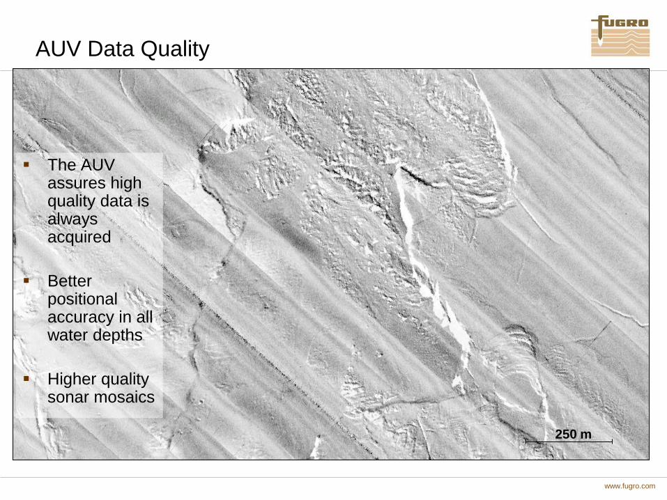
AUV Data Quality
The AUV assures high quality data is always acquired
Better positional accuracy in all water depths
Higher quality sonar mosaics
www.fugro.com
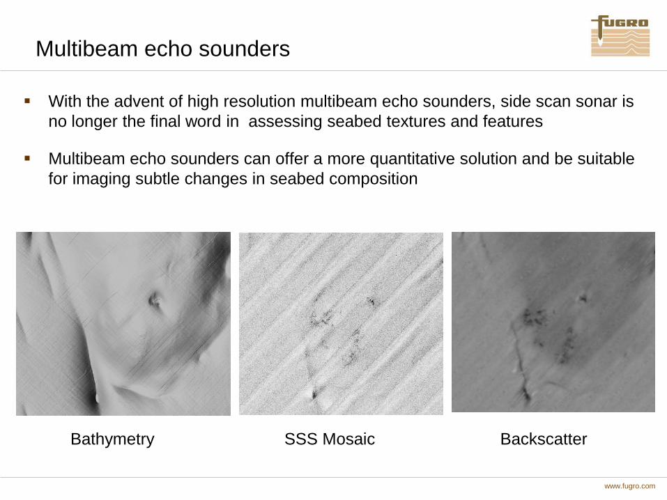
Multibeam echo sounders
With the advent of high resolution multibeam echo sounders, side scan sonar is
no longer the final word in assessing seabed textures and features
Multibeam echo sounders can offer a more quantitative solution and be suitable
for imaging subtle changes in seabed composition
Bathymetry SSS Mosaic Backscatter

www.fugro.com
Sub bottom profilers
Most of these systems are towed behind the vessel, either at the sea-surface
(Surface Tow), just below the sea-surface (Sub Tow) or just above the seabed
(Deep Tow)
These towed sensors are linked to the vessel via an umbilical tow cable through
which the profiler unit is triggered, and the reflected data is transported back to
the vessel to be processed, displayed and recorded
Surface Tow and Sub Tow are very susceptible to weather affects, Deep Tow to
positioning issues
Autonomous Underwater Vehicles (AUVs) are being increasingly employed as
platforms for all types of analogue sensor, including profilers. There are many
potential advantages of AUVs - these include short line turns and good
positioning in deep water as well as low noise and superior data resolution
www.fugro.com
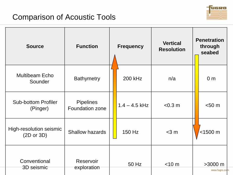
Comparison of Acoustic Tools
Source Function Frequency Vertical
Resolution
Penetration
through
seabed
Multibeam Echo
Sounder Bathymetry 200 kHz n/a 0 m
Sub-bottom Profiler
(Pinger)
Pipelines
Foundation zone 1.4 – 4.5 kHz <0.3 m <50 m
High-resolution seismic
(2D or 3D) Shallow hazards 150 Hz <3 m <1500 m
Conventional
3D seismic
Reservoir
exploration 50 Hz <10 m >3000 m
www.fugro.com
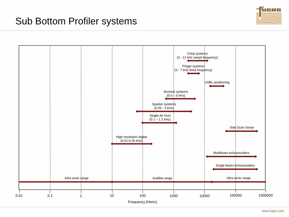
Sub Bottom Profiler systems
Chirp systems
(3 - 11 kHz swept frequency)
Pinger systems
(3 - 7 kHz fixed frequency)
Boomer systems
(0.5 – 5 kHz)
Sparker systems
(0.05 - 4 kHz)
USBL positioning
High resolution digital
(0.01-0.25 kHz)
Infra sonic range Audible range Ultra sonic range
Single beam echosounders
Multibeam echosounders
Side Scan Sonar
10 1 0.1 100 1000 10000 100000 1000000 0.01
Frequency (Hertz)
Single Air Gun
(0.1 – 1.2 kHz)

www.fugro.com
Equipment
Comparison of common sub-bottom profiler systems:
Operating
Frequency
Max. Depth of
Penetration
Resolution Type of Source Typical Energy
Output
Pinger ~3.5 - 7 kHz
(Fixed)
30 – 40
metres
~0.3 metres
Piezoelectric
Transducer
~2 joules
Chirp 3.5 – 11 kHz
(Swept)
40 – 50
metres
~0.3 metres
Piezoelectric
Transducer
~2 joules
Boomer ~0.5 – 5 kHz
~100 metres ~0.5 metres Electro-
mechanical
Transducer
~200 - 1500
joules
Sparker
0.05 - 4 kHz ~200 metres 1 – 10
metres
Electric Spark
~4 - 24 kilojoules
Single Air
Gun
100 – 1200 Hz ~900 metres 1 – 10
metres
Compressed
Air Pressure
Wave

www.fugro.com
AUV Data Quality
Planned well location6405/10-A
Approximately 125 m
Approximately8 m @ 1600 m/s
Fix numberand time (GMT)
Vessel’s track
CLAY prone sedimentwith variable
sand/silt fractions
Approximately 5.5 mthick post Storegga
drape
Hull-mounted Pinger AUV Chirp
Approximately
8m @ 1600m/s
Approximately 125 m WD=850m

www.fugro.com
Comparison of sub-bottom profiler system data:
Hull-Mounted Pinger
Surface-Tow Boomer
Deep-Tow Sparker
Single Air Gun
www.fugro.com
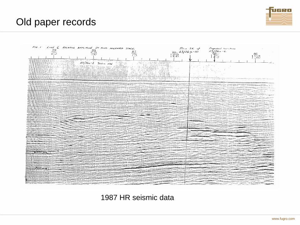
Old paper records
1987 HR seismic data

www.fugro.com
2D vs 3D Resolution
3D Exploration Seismic Data
Approx. 550m
2D High-resolution Seismic Data

www.fugro.com
The benefit of 3D migration

www.fugro.com
Conventional 3D vs Short-Offset Processing

www.fugro.com
Magnetic Influence of Iron

www.fugro.com
Environmental Issues
JNCC guidelines necessitate environmental surveys in sensitive areas
• Pockmark fields – active venting encourages marine life growth and reef development
• Sabellaria – tube worms
• Herring spawning grounds
• “Reefs”
Seabed photos & sediment grab samples taken as part of geophysical survey
EIA becoming standard part of site surveys
Geophysicists working with marine biologists
Sabellaria spinulosa
Lophelia pertusa
www.fugro.com
General Interpretation Guidelines
From UKOOA Guidelines:
• Use all sources of available data - top hole well data,
borehole data, exploration seismic data, adjacent rig
site survey data, regional geological data (e.g. BGS,
NPD), in-house knowledge of the area, previous drilling
experience in the area.
• Interpret within regional framework.
• Use seismic workstations - enhanced display options
and attribute analysis.

www.fugro.com
Limitations
Echo sounders - have improved number of beams and focusing, and
information on pitch, yaw and heave – but need more stable platform
Side scan sonars – higher frequency = lower range
Backscatter – improved processing and automatic correlation
Camera – ground truthing – mounted on ROV/AUV
Magnetometer – lack of range
Sub bottom profilers – multichannel streamers
2D HR – close line spacing, process as pseudo 3D – Multi Azimuth surveys
3D data – Short offset reprocessed
3D data – Impedance/AVO/Depth cubes

www.fugro.com
Step changes and the future
Step Changes
Multibeam Echo sounders
AUVs
Interpretation software
Visualisation software
Future Developments
Synthetic aperture sonar systems
Advances in sub-bottom profilers
Magnetometer arrays
Better pooling of information
Better preparation before survey – desk studies
www.fugro.com
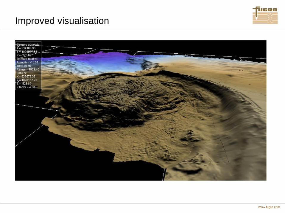
Improved visualisation

www.fugro.com
Thank You