site characterization report for duke energy …5.3.4 phase 2 wells duke energy selected 11...
TRANSCRIPT

*S&MECelebrating 35 Years
1973 2008
June 30, 2008
Duke EnergyMail Code ECI2K526 South Church StreetCharlotte, North Carolina 28202
Attention: Mr. Gregory D. Robison, P.E.
Reference: Site Characterization ReportGroundwater Protection InitiativeDuke Energy McGuire Nuclear StationHuntersville, North CarolinaS&ME Project 1264-06-724
Dear Mr. Robison:
S&ME, Inc. (S&ME) is pleased to present this Site Characterization Report for theGround Water Protection Initiative at Duke Energy's McGuire Nuclear Station inHuntersville, North Carolina. Our Ground Water Protection Initiative activities wereprovided inaccordance with our January 24, 2007 Proposal 07064, Duke Energy'sauthorization Contract 00080694, and our Professional Services Agreement0233032.04/MI 1342 002 with Duke Energy.
This Site Characterization Report is.comprised of two volumes that include discussion ofthe Ground Water Protection Initiative Project, site activities, and findings, withsupporting tables, figures, and record documents in associated appendices. Conclusionsinclude development and discussion of a Site Conceptual Hydrogeologic Model.
S&ME-is honored to have supported Duke Energy on this important Ground WaterProtection Initiative. We trust this information is responsive to your, needs at this time. Ifyou have questions regarding the Site Characterization Report or desire our assistancefurther, please do not hesitate to contact us.
Sincerely,S&ME, Inc.
.. i5.W .,C Ate'
Courtney Withers, GIT JulieR. Petersen, PG , SEALStaff Professional Senior Geologist , ., ,^ 2 icrwithers(2smeinc.com [email protected] lo o,-,
Senior Reviewed by Lairy Armstrong, PE, Senior EngineerlVice-President Ee1exO1%••
S&ME, INC.. 9751 Southern Pine Boulevard / Charlotte, NC 28273-5560/p 704.523,4726 f'704:525.3953 / www.smeinb comr\

Ground Water Protection Initiative Site Characterization Report S&ME Project 1264-06-724Duke Energy McGuire Nuclear Station June 30, 2008
TABLE OF CONTENTS (VOLUME 1)
SECTION PAGE
1.0 INTRODUCTION AND PURPOSE ......................................................... 1
2.0 SITE DESCRIPTION ........................................................................ 2
2.1 Site Location .................................................................................................... 22.2 Site Setting ...................................................................................................... 2
2.2.1 Lake Norman ............................................................................................... 3
3.0 STATION DESCRIPTION ............................................................... . 4
3.1 Overview of Primary Plant Building Construction ........................................ 43.1.1 Reactor Buildings ......................................................................................... 43.1.2 Auxiliary Building ......................................................................................... 53.1.3 Diesel Generator Buildings .......................................................................... 53.1.4 Turbine Buildings ........................................................................................ 53.1.5 Service Building .......................................................................................... 53.1.6 Groundwater Drainage (WZ) System ........................................................... 53.1.7 Landfarms and Landfills .............................................................................. 7
3.2 Overview of Plant Water Use ......................................................................... 73.2.1 Cooling and Service Water Systems ........................................................... 7
3.2.1.1 Intake Structure .................................................................................... 73.2.1.2 Conventional Wastewater Treatment System (WC) Ponds .................. 83.2.1.3 Discharge Structure ............................................................................. 8
3.2.2 Standby Nuclear Service Water Pond ......................................................... 83.2.3 Waste Water Collection Basin ...................................................................... 93.2.4 Domestic Water and Sanitary Waste .......................................................... 93.2.5 Groundwater Supply Wells .......................................................................... 93.2.6 Groundwater Use Summary ...................................................................... 103.2.7 Storm Water ............................................................................................... 10
4.0 OVERVIEW OF STATION HYDROGEOLOGIC SETTING ............... 11
4.1 Regional Physiographic Province ................................................................ 114.2 Regional Geology ......................................................................................... 124.3 Regional Hydrogeology ............................................................................... 124.4 Site Geology .................................................................................................. 154.5 Site Groundwater ............................................................................................ 15
4.5.1 Site Hydrostratigraphic Units ...................................................................... 16
5.0 SOURCE/SOURCE PATHWAY EVALUATION AND MONITORINGLOCATIONS ....................................................................................... . 17
5.1 Contaminants of Interest and Their Fate in the Environment .................. 17
Table of Contents

Ground Water Protection Initiative Site Characterization Report S&ME Project 1264-06-724Duke Energy McGuire Nuclear Station June 30, 2008
5.1.1 Tritium .................................................................................................... . . 175.1.1.1 K d V alues for Tritium ............................................................................ 18
5.2 Structures, Systems and Component Evaluation ...................................... 185.2.1 Risk Assessment Process ......................................................................... 185.2.2 Risk Assessment Results ......................................................................... 195.2.3 Operating Experience ............................................................................. 19
5.3 Groundwater Protection Monitoring Well Location Selections ................. 205.3.1 Existing Boring Information ...................................................................... 215.3.2 Existing Well Information ........................................................................... 215.3.3 Phase I W ells ........................................................................................... 225.3.4 Phase 2 W ells ........................................................................................... 225.3.5 Surface Water Sampling Locations ........................................................... 23
6.0 REGULATORY APPROVALS AND DOCUMENTATION ................... 24
7.0 FIELD METHODS FOR GROUNDWATER MONITORING WELL
INSTALLATIONS .................................................................................. 25
7.1 Preliminary Well Locations .......................................................................... 257.2 Utility Clearance and Final Well Locations .................................................. 257.3 Plant Access Training, Mobilization, Safety Orientation, and Security Access
.. o....==..=,.,,.====...,,......==,, ...........=,,°°,,°,,.,,. ................................................ 257.4 Soil Test Borings, Soil Classification, Soil Testing .................................... 257.5 Rock Coring and Classification .................................................................... 267.6 Permeability and Packer Testing ..... ............................................................. 267.7 Well Construction ......................................................................................... 277.8 Well Development ......................................................................................... 297.9 Slug Testing .................................................................................................. 297.10 Equipment Cleaning and Investigative Derived Waste Management ....... 297.11 Groundwater Monitoring Well Location Survey ........................................ 307.12 Groundwater Sample Collection ............................................................... 307.13 Groundwater Sample Analysis .................................................................. 31
8.0 SUMMARY OF FINDINGS .................................................................. 32
8.1 Geologic Summary ....................................................................................... 328.1.1 Hydrostratigraphic Units ........................................................................... 328.1.2 Soil Porosity and Specific Yield ................................................................ 338.1.3 Partially Weathered/Fractured Rock and Sound Rock Secondary Porosity.. 34
8.2 Hydrogeologic Findings ................................................................................ 348.2.1 Groundwater Occurrence and Flow .......................... ............................... 348.2.2 Groundwater Gradients .............................................................................. 36
8.2.2.1 H orizontal G radients ............................................................................ 368.2.2.2 V ertical G radients ................................................................................ 37
8.2.3 Hydraulic Conductivities ........................................................................... 378.2.4 Groundwater Flow Rates ....................................... 38
8.3 Groundwater Quality .................................................................................... 38
Table of Contents

Ground Water Protection Initiative Site Characterization Report S&ME Project 1264-06-724Duke Energy McGuire Nuclear Station June 30, 2008
8.3.1 Shallow Groundwater Condition Wells ...................................................... 398.3.2 Deeper Groundwater Conditions Wells .................................................... 39
8.4 Site Conceptual Hydrogeologic Model ........................................................ 39
9.0 CONCLUSIONS .............................................................................. 41
9.1 Data Gaps and Unknowns/Uncertainties .................................................... 419.2 Groundwater Monitoring ............................................................................. 41
10.0 QUALIFICATIONS ....................................................................... 42
11.0 SELECTED REFERENCES ............................................................ 43
Table of Contents

Ground Water Protection Initiative Site Characterization ReportI'hlkA Fnnrrnv Mnciuirp Nijc.Ipr Statinn
S&ME Project 1264-06-724.hinn fl •2AA•
Duke Enernv McGuire Nuclear Station June 30 2008
TABLES AND CHARTS (VOLUME 1)
WITHIN TEXT
TABLE T-1TABLE T-2
TABLE T-3
TABLE T-4
TABLE T-5TABLE T-6TABLE T-7
LAKE NORMAN SUMMARY TABLEREACTOR, AUXILLIARY, DIESEL GENERATOR BUILDINGS WZSUBSYSTEM SUMP SUMMARYTURBINE AND SERVICE BUILDINGS WZ SUBSYSTEM SUMPSUMMARYCONVENTIONAL WASTEWATER TREATMENT SYSTEM (WC)PONDS SUMMARYGROUNDWATER SUPPLY WELLS SUMMARYGROUNDWATER USE SUMMARYMEAN HYDRAULIC CONDUCTIVITY SUMMARY
WITHIN TABLES TAB
TABLE 1 MONITORING WELL CONSTRUCTION SUMMARYTABLE 2 HYDROSRATIGRAPHIC UNITS SUMMARYTABLE 3 SOIL TESTING SUMMARY (SOIL POROSITY AND SPECIFIC YIELD)TABLE 4 SECONDARY POROSITY SUMMARY (PARTIALLY
WEATHERED/FRACTURED ROCK AND SOUND ROCK)TABLE 5 GROUNDWATER LEVEL SUMMARYTABLE 6 HYDROSTRATIGRAPHIC UNITS AND GROUNDWATER
CONDITIONS SUMMARYTABLE 7 VERTICAL GRADIENTS SUMMARYTABLE 8 PERMEABILITY TESTING SUMMARY (OPEN-HOLE FALLING HEAD,
PACKER, AND SLUG TESTING)CHART 8A MEAN HYDRAULIC CONDUCTIVITY CHARTTABLE 9 GROUNDWATER VELOCITY ESTIMATES SUMMARYTABLE 10 TRITIUM IN GROUNDWATER SUMMARYTABLE 11 SAMPLE COLLECTION SUMMARY MEASUREMENTS -
FEBRUARY 2008
Table of Contents

Ground Water Protection Initiative Site Characterization Report S&ME Project 1264-06-724Duke Energy McGuire Nuclear Station June 30, 2008
FIGURES (VOLUME 1)
WITHIN TEXT
FIGURE F-1 PHYSIOGRAPHIC PROVINCES OF NORTH CAROLINAFIGURE F-2 GEOLOGIC BELTS OF THE CAROLINASFIGURE F-3 PRINCIPLE COMPONENTS OF GROUNDWATER SYSTEM IN
PIEDMONT GEOLOGIC PROVINCEFIGURE F-4 CONCEPTUAL GROUNDWATER FLOW SYSTEM IN PIEDMONT
GEOLOGIC PROVINCE
WITHIN FIGURES TAB
FIGURE 1 STATION LOCATION AND PROPERTY MAPFIGURE 2 UNITED STATES GEOLOGICAL SURVEY MAPFIGURE 3 STATION SITE PLAN AND FEATURESFIGURE 4 GROUND WATER PROTECTION INITIATIVE MONITORING WELLSFIGURE 5 HYDROGEOLOGIC CROSS-SECTION LOCATIONSFIGURE 6 HYDROGEOLOGIC CROSS-SECTION A-A', B-B'FIGURE 7 HYDROGEOLOGIC CROSS-SECTION C-C', D-D'FIGURE 8 HYDROGEOLOGIC CROSS-SECTION E-E', F-F'FIGURE 9 HYDROGEOLOGIC CROSS-SECTION G-G', H-H'FIGURE 10 POTENTIOMETRIC GROUNDWATER MAP
- SHALLOW WITHOUT FOUNDATION DEWATERING DATAFIGURE 11 POTENTIOMETRIC GROUNDWATER MAP
- SHALLOW WITH FOUNDATION DEWATERING DATAFIGURE 12 POTENTIOMETRIC GROUNDWATER SURFACE
- DEEPER WITHOUT FOUNDATION DEWATERING DATAFIGURE 13 POTENTIOMETRIC GROUNDWATER SURFACE
- DEEPER WITH FOUNDATION DEWATERING DATAFIGURE 14 VERTICAL GRADIENTSFIGURE 15 TRITIUM CONCENTRATIONS IN GROUNDWATER
- FEBRUARY 2008
Table of Contents
Ground Water Protection Initiative Site Characterization Report S&ME Project 1264-06-724Duke Energy McGuire Nuclear Station June 30, 2008
APPENDICES (VOLUME 2)
APPENDIX A - HISTORICAL DRAWINGS:
PLATE 1 - REACTOR BLDG. & AUX. BLDG. GROUNDWATER DRAINAGESYSTEM PLANS, SECTIONS, AND DETAILS, SHEET NO. 1 (MC 1220-21)
PLATE 2 - REACTOR BLDG. & AUX. BLDG. GROUNDWATER DRAINAGESYSTEM PLANS, SECTIONS, AND DETAILS, SHEET NO. 2 (MC 1220-31)
PLATE 3 - UFSAR FIGURE 2.4 (Plot Plan and Site Area)PLATE 4 - GENERAL SITE PLAN (MC 1002-01.00)
APPENDIX B - SOURCE AND SOURCE PATHWAY RISK ASSESSMENT
TABLE B-1 SOURCE AND SOURCE PATHWAY RISK ASSESSMENTRESULTS
APPENDIX C - SOIL TEST BORING FIELD REPORTS AND MONITORING WELLINSTALLATION RECORDS FOR SELECTED EXISTING McGUIRE WELLS
APPENDIX D - REGULATORY DOCUMENTATION:
MECKLENBURG COUNTY SUBSURFACE INVESTIGATION APPLICATIONAND PERMITMECKLENBURG COUNTY MONITOR WELL REGISTRATION FORMSNCDENR WELL RECORDS
APPENDIX E - BORING LOGS, ROCK CORE LOG, WELL LOG, SOIL PHOTOS,ROCK PHOTOS, PERMEABILITY TESTS (BOREHOLE TESTS,SLUG TESTS), PARTICLE SIZE ANALYSIS OF SOILS, FETTER ANDBEAR DIAGRAMS (ARRANGED BY WELL LOCATION)
APPENDIX F - SOIL DISPOSAL EMAIL DOCUMENTATION
APPENDIX G - LABORATORY ANALYTICAL REPORTS - FEBRUARY 18-21, 2008
APPENDIX H - VERTICAL GRADIENT CALCULATION SHEETS
APPENDIX I - HISTORICAL BORING RECORDS (ON COMPACT DISK)
Table of Contents

Ground Water Protection Initiative Site Characterization Report S&ME Project 1264-06-724Duke Energy McGuire Nuclear Station June 30, 2008
1.0 INTRODUCTION AND PURPOSE
Water containing trace amounts of various radioactive materials is normally released from U.S.nuclear power plants under controlled, monitored conditions that meet conservative NuclearRegulatory Commission (NRC) limits to protect public health and safety. Recently, severalinstances of unintended, abnormal releases of radioactive liquids to the environment wereidentified. Materials detected to date in groundwater around nuclear power plants includeTritium and Strontium 90 (NRC, 2007). Of these two materials, Strontium-90 is only associatedwith specific, isolated plant systems, such as the Spent Fuel Pool. Tritium is much moreprevalent in plant systems than Strontium-90, and is thus considered a much better indicator ofpotential radioactive releases. As such, while Strontium-90 as a material is monitored by DukeEnergy on a specific basis, tritium and potential sources of tritium are the focus of this GroundWater Protection Initiative.
In 2006, the Nuclear Energy Institute (NEI) announced the U.S. commercial nuclear powerindustry's unanimous approval of a voluntary initiative to improve the industry's management ofgroundwater protection issues. More specifically, the initiative addressed radiological releases togroundwater, with tritium (H3) being the primary indicator. The initiative calls for theestablishment of on-site groundwater monitoring programs at operating nuclear power plants(EPRI, 2007). To this end, Duke Energy, Devine Tarbell & Associates, Inc. (DTA) and S&ME,Inc. (S&ME) formed a collaborative team to design and install comprehensive groundwatermonitoring well networks at Duke Energy's operating nuclear power fleet comprising McGuireNuclear Station in Huntersville, North Carolina, Catawba Nuclear Station in York, SouthCarolina, and Oconee Nuclear Station in Seneca, South Carolina. The overriding purposes of thegroundwater monitoring well networks are:
1. Establish post-construction hydrogeology of the operating nuclear plant site and developa Site Conceptual Model for understanding groundwater presence and movement at theplant sites; and,
2. Establish site-specific monitoring well networks for groundwater protection monitoringcomprising both near-field (nearer potential radiological tritium sources) and far-field(further from potential radiological tritium sources) well arrays.
This Ground Water Protection Initiative Site Characterization Report presents theimplementation of and findings from the activities associated with the Ground Water ProtectionInitiative at the Duke Energy McGuire Nuclear Station (McGuire) in Huntersville, NorthCarolina. This report establishes the foundation for the Radiological Ground Water ProtectionProgram at McGuire (NSD-517).
1

Ground Water Protection Initiative Site Characterization Report S&ME Project 1264-06-724Duke Energy McGuire Nuclear Station June 30, 2008
2.0 SITE DESCRIPTION
2.1 Site Location
McGuire is located in North Carolina, in the northwestern portion of Mecklenburg County,adjacent to Lake Norman. The McGuire site is approximately 5 miles west of Interstate 1-77.Huntersville, North Carolina, the nearest town, is located approximately 6 miles to the east. Thesite is located at Latitude 35 degrees-25 minutes-59 seconds North and at Longitude 80 degrees-56 minutes-55 seconds West. The location of the site is shown on Figure 1, Station Locationand Property Map.
2.2 Site Setting
McGuire lies in the Piedmont Physiographic Province. The Piedmont is a northeast trendingzone that varies in width from about 80 to 120 miles. The site is bounded on the northwest bythe Blue Ridge Province and on the southeast by the Atlantic Coastal Plain Province. The plateaugenerally slopes southeastward with an elevation range from about 1200 feet to 400 feet.
McGuire lies within a groundwater region that is part of the Piedmont Groundwater Province.Groundwater recharge in this area is derived entirely from infiltration of local precipitation.Groundwater recharge occurs in areas of higher topography (i.e., hilltops) and groundwaterdischarge occurs to areas of lower topography (i.e., valley creeks and streams).
McGuire is bounded to west by the Catawba River and to the north by the 32,510 acre LakeNorman. Lake Norman is impounded by Duke Power's Cowans Ford Dam hydroelectric station,which is located immediately west of the site and on the Catawba River channel. The plantproperty and off-site features are shown on Figure 1, Station Location and Property Map.
McGuire has a 2,500 foot radius Exclusion Zone covering approximately 450 acres, of this totalarea, there is approximately 291 acres of land. The remainder of the Exclusion Area includesportions of Lake Norman and the McGuire Discharge Canal. Within the Exclusion Zone there isapproximately 145 acres of non-forested land. This non-forested land consists largely ofgeneration and maintenance facilities, parking lots, roads, storage yards, and mowed grass.Included in this area is the 32.9 acre (13.3 ha) Standby Nuclear Service Water Pond and a 10.2acre (4.1 ha) Wastewater Collection Basin. Young and mid-aged mixed hardwood-pine and pine-mixed hardwood communities dominate the majority of the 102 acres (41.0 ha) of the ExclusionZone not occupied by plant structures or facilities. This acreage varies in elevation from 650 feetto 800 feet above mean sea level (msl).
Land use nearby McGuire is primarily comprised of residential development, with limitedcommercial development (e.g., schools, restaurants, service stations) and institutional (e.g.,churches) development. Located near the major urban center of Charlotte, near majortransportation routes (1-77 and 1-85), and Lake Norman, the area around the McGuire plant isexperiencing rapid change from a rural to a suburban environment.
2

Ground Water Protection Initiative Site Characterization ReportDuke Energv McGuire Nuclear Station
S&ME Project 1264-06-724June 30, 2008
2.2.1 Lake Norman
Lake Norman serves as the cooling water source for McGuire. Lake Norman is North Carolina'slargest man-made lake and extends 34 miles in length between Lookout Shoals Lake andMountain Island Lake. Lake Norman was formed from the impoundment of the Catawba Riverand achieved full pond in 1964.
Lookout Shoals Lake, Mountain Island Lake, and Lake Norman are part of the Catawba-WatereeProject, and are owned and operated by Duke Power, a division of Duke Energy and licensed bythe Federal Energy Regulatory Commission (FERC) as FERC Project 2232. The Catawba-Wateree Project consists of 11 lakes on the Catawba River, which are operated for hydroelectricpower. Lake Norman is the largest in the Catawba chain of lakes. The major tributaries for LakeNorman are the Catawba River, Lyle Creek, and Buffalo Shoals Creek.
Table T-1, Lake Norman Summary Data, below, provides a summary of selected data for LakeNorman.
" 'TABLE T-'LAKE NORMAN SUMMARY DATA.
Full Pond Elevation 760 feet (msl)Maximum Drawdown 25 feetFull Pond Surface Area 32,500 acresFull Pond Volume 1.09 x 10⁶ acre-feetShoreline Length 520 milesMean Depth 33 feetMaximum Depth 120 feetDrainage Area 1800 square milesAnnual Mean Flow (at Cowans Ford Dam) 2670 cubic feet per secondMinimum Average Daily Flow (FERC) 311 cubic feet per second
In addition to serving the needs of the McGuire, Marshall, and Cowans Ford power plants, LakeNorman is a source of municipal drinking water for several cites in the region.
3

Ground Water Protection Initiative Site Characterization Report S&ME Project 1264-06-724Duke Energy McGuire Nuclear Station June 30, 2008
3.0 STATION DESCRIPTION
3.1 Overview of Primary Plant Building Construction
This section provides an overview description of McGuire and construction elements of theprimary plant buildings of significance relative to groundwater movement and monitoring. Plantbuildings and features are depicted on Figure 3, Station Site Plan and Features.
McGuire Unit 1 began commercial operation in June 1981; Unit 2 began commercial operationin March 1983.
The primary plant buildings at McGuire are comprised of two Reactor Buildings, one sharedAuxiliary Building, two Diesel Generator Buildings, two Turbine Buildings, and one sharedService Building, collectively considered the "Power Block". Other shared support featuresinclude the water Intake Structure, the water Discharge Structure, Conventional Waste WaterTreatment Ponds, the Standby Nuclear Service Water Pond, the Waste Water Collection Basinand the Radwaste Facility Building. In addition to these primary buildings and features, thereare ancillary office buildings and other facilities at the site used by and for McGuire supportstaff.
Additionally, McGuire has operated two landfarms and two landfills on site. While not thesubject of this site characterization effort, these locations are of interest for the overallradiological ground water protection program and are discussed briefly herein for completeness.
3.1.1 Reactor Buildings
McGuire Units I and 2 each employ a pressurized water reactor Nuclear Steam Supply System(NSSS) with four coolant loops which were furnished by Westinghouse Electric Corporation. Inthe reactor itself, control rods and boron are used to control the amount of nuclear fission. Theprimary cooling system for the reactor is known as the Reactor Coolant System. The ReactorBuildings house the Reactor Coolant System for each unit.
The Reactor Buildings are constructed on bedrock at elevation 717.0 feet msl (relative to asurrounding plant grade level of approximately 760 feet msl) with interior excavation as deep aselevation 688.4 feet msl.
The Reactor Building structure is part of the containment system that is designed to ensure thatan acceptable upper limit of leakage of radioactive material is not exceeded under Design BasisEvents.
A key component of interest in this Ground Water Protection Initiative is the fuel transfer tubewhich runs between the spent fuel pool in the Auxiliary Building and the containment fueltransfer canal (also called the refueling canal) in the Reactor Building. The fuel transferpenetration, a steel subcomponent of the Steel Containment portion of the Reactor Building, isprovided for transfer of fuel to and from the fuel pool and the containment fuel transfer canal.
4

Ground Water Protection Initiative Site Characterization Report S&ME Project 1264-06-724Duke Energy McGuire Nuclear Station June 30, 2008
3.1.2 Auxiliary Building
The single Auxiliary Building surrounds the Unit I and Unit 2 Reactor Buildings, and houses theRadiation Control Area containing the reactor support systems, including the New Fuel StorageFacility and Spent Fuel Pool. Each unit at McGuire has a separate fuel handling facility thatincludes a New Fuel Storage Facility and a Spent Fuel Pool, located (approximately) in thenorthwest (Unit 1) and northeast (Unit 2) portions of the Auxiliary Building.
Key components of interest in this Ground Water Protection Initiative are sumps within theAuxiliary Building that may encounter leaking fluid and the spent fuel pool which operatingexperience has indicated to be the source of groundwater contamination at other utilities. TheAuxiliary Building is supported by a reinforced concrete foundation mat that bears either directlyon rock or on "fill" concrete. Positioned at the top of fill concrete below the foundation slabs,largely at elevation 712 feet msl, there is a grid of interconnected flow channels (refer to Section3.1.6).
3.1.3 Diesel Generator Buildings
The two Diesel Generator Buildings are located west and east of Units 1 and 2, respectively.The diesel generators housed in each of these buildings provide off-line and back-up power forfacility support systems. The Diesel Generator Building is supported by a reinforced concretefoundation mat that bears either directiy on rock or on "fill" concrete. Positioned at the top offill concrete below the foundation slabs, ranging between elevations 726 feet msl and 729.5 feetmsl, there is a grid of interconnected flow channels (refer to Section 3.1.6).
3.1.4 Turbine Buildings
The two Turbine Buildings, located south of each Reactor Building, house the main turbines,electrical generators and the supporting equipment such as the main condensers and feedwaterpumps. The Turbine Buildings are steel frame structures supported on reinforced concretesubstructures. The Unit 1 Turbine Building (westernmost unit) is supported on deep foundationsbearing on bedrock. The presence of the compressible soils, with variable depth, beneath thesouth and west portions of Unit 1 would allow excessive total and differential movements if soil-supported foundations were used. Drilled straight shaft caissons, end-bearing on the bedrock,were used. The Unit 2 Turbine Building (easternmost unit) is supported on a mat foundationbearing on the dense soils, partially weathered rock and rock.
3.1.5 Service Building
The single, shared Service Building is situated between the Turbine Buildings and housessupport systems shared between Unit I and Unit 2. The southern portion of the Service Buildingis underlain by compacted soil and is supported on end bearing caissons.
3.1.6 Groundwater Drainage (WZ) System
Design and construction of the Reactor, Auxiliary, and Diesel Generator Buildings includes adewatering system used to reduce the hydrostatic pressures on the foundations and foundationwalls. A permanent groundwater drainage system is installed as shown on Plate 1, ReactorBldg. And Aux. Bldg. Groundwater Drainage System Sheet No. 1 (MC-1220-21) and Plate 2,
5

Ground Water Protection Initiative Site Characterization Report S&ME Project 1264-06-724Duke Energy McGuire Nuclear Station June 30, 2008
Reactor Bldg. And Aux. Bldg. Groundwater Drainage System Sheet No. 2 (MC-1220-31)(Appendix A). The drainage system is designed to create and permanently maintain a normalgroundwater level at or near the base of the foundation mat and basement walls, thus eliminatingthe uplift of hydrostatic forces. This groundwater drainage system consists of a waffle-like gridof underdrains, constructed integrally with the building foundation, and continuous exterior walldrains. Being constructed integrally with the foundations, the elevation of the groundwaterdrainage system varies, but is generally at elevation 717 feet msl underneath the ReactorBuildings, at elevation 712 feet msl for the Auxiliary Building, and between elevations 726 feetmsl and 729.5 feet msl underneath the Diesel Generator Buildings. Likewise, the continuousexterior wall drains vary in elevation, but approximate the elevations of the foundation grid.
The foundation underdrains and the exterior wall drains discharge into three sumps locatedadjacent to the Auxiliary Building, described below in Table T-2, Auxiliary Building WZSystem Sump Summary:
Physical LocationDescription
Within AuxiliaryBuilding, between
column lines BB-CCand 51-52
Within AuxiliaryBuilding, between
column lines BB-CCand 61-62
Within AuxiliaryBuilding ,near column
line RR between columnlines 54 and 55
Size 10 f1x 10 ftx 15 ft deep 10 fix 10 fix 15 ft deep 17 ftx 17 ftx 12 ft deepBottom Elevation for
Inlet Pipe and Wooden 712 feet msl 712 feet msl 712 feet mslDrains
Inlet Pipe Size 8 inch CMP 8 inch CMP 8 inch CMPBottom Sump 702 feet msl 702 feet msl 704 feet msl
ElevationPump Discharge 713.3 feet msl 713.3 feet msl 716.3 feet msl
Elevation
Groundwater Sumps A and B are used to collect normal groundwater and/or potentiallycontaminated groundwater. The groundwater or contaminated liquid collected in Sumps A or Bwould be pumped to the Turbine Building sumps (Sump A pumps to the Unit 1 Turbine BuildingSump and Sump B pumps to the Unit 2 Turbine Building Sump). Normal sump dischargeswould then be pumped to the Conventional Waste Water Treatment System; contaminated sumpdischarges could be directed to the Liquid Waste Monitor and Disposal System. Groundwater orcontaminated liquids collected in Sump C would be pumped to a free outfall at the storm drainsystem which discharges into the Standby Nuclear Service Water (SNSW) Pond. Typical flowfrom Sump C is on the order of 10 to 20 gpm. Inflow to the SNSW Pond is passed to the WasteWater Collection Basin through the SNSW Pond outlet facility.
Eleven permanent groundwater monitors are installed around the perimeter of the Auxiliary andReactor Building exterior walls to monitor the groundwater level in the zoned wall filter. Seveninterior monitors, instrumented through holes in the wall, are mounted inside the Auxiliary andDiesel Generator Building. One exterior groundwater monitor, instrumented in a drilled casedwell, drilled into the zoned filter is located inside the Unit 2 Equipment Staging Building. Three
6

Ground Water Protection Initiative Site Characterization Report S&ME Project 1264-06-724Duke Energy McGuire Nuclear Station June 30, 2008
exterior monitors, instrumented in cased wells drilled into the zoned wall filter, are locatedoutside the Reactor and Auxiliary Building. All eleven monitors provide three points of alarm toalert operators to a rise in groundwater.
3.1.7 Landfarms and Landfills
McGuire has operated two landfarms and two landfills on site. While not directly tied to thedaily operation of McGuire and also not the subject of this site characterization effort,nonetheless these locations are of interest for the overall radiological ground water protectionprogram.
Landfarm #1 is located next to the Catawba River, immediately downstream of Cowans FordDam. Landfarm #1 is closed and no longer used. Landfarm #2 is located near the transmissionyard, south of highway NC-73. Landfarm #2 is also closed. Landfill #1 is located in the samearea as Landfarm #1 and is closed. Landfill #2 is located south of the transmission yard, south ofhighway NC-73. The sludge from the Initial Holdup Pond is now de-watered and disposed of inLandfill #2, which is the only open site of the four mentioned here. Monitoring wells exist forboth Landfill #1 and Landfill #2.
3.2 Overview of Plant Water Use
This section provides an overview description of water use at McGuire of significance relative togroundwater movement and monitoring.
3.2.1 Cooling and Service Water Systems
McGuire uses water from Lake Norman for cooling and process water. The average dailywithdrawal from Lake Norman for the cooling water and other service water systems is 2626million gallons per day (mgd). The average daily discharge via pass through to Lake Normanfrom McGuire is 2404 mgd. Combined average flows of 0.9819 mgd from the ConventionalWastewater Treatment System (0.3485 mgd) and the Waste Water Collection Basin (0.6334mgd) is discharged to the Catawba River below the Cowan's Ford Dam.
3.2.1.1 Intake Structure
The Condenser Circulating Water (RC) System withdraws water from Lake Norman via theCondenser Circulating Water Intake Structure. This system, in turn, supplies water to other plantsystems, including the Conventional Low Pressure Service Water System and the Fire ProtectionSystem jockey pumps. The Fire Protection System withdraws water from Lake Norman forplant fire protection. The Condenser Circulating Water Intake Structure houses the three mainfire pumps.
The Condenser Circulating Water Intake Structure is located west of the McGuire Power Blockand is a reinforced concrete structure built into the east embankment of Cowans Ford Dam. TheRC Intake Structure is designed to withdraw water from the lake via normal and low level intakeelevations. The low level intake cooling water portion of the RC System is designed to take coolwater from the lower levels of Lake Norman and mix it with the warmer water at the CondenserCirculating Water Intake Structure during times of high lake water temperature.
7

Ground Water Protection Initiative Site Characterization Report S&ME Project 1264-06-724Duke Energy McGuire Nuclear Station June 30, 2008
3.2.1.2 Conventional Wastewater Treatment System (WC) Ponds
The Conventional Wastewater Treatment (WC) System receives all secondary side plant wastewater (except sanitary sewage), monitors it for radioactivity, treats it through a system of pondswith chemical treatment and aeration capabilities and discharges it to the Catawba River at aquality equal to or better than applicable State and Federal Water Quality Standards. Ifradioactivity from any source approaches IOCFR20 limitations, it is handled in-plant asradioactive waste by the Liquid Waste Monitor and Disposal System and the Solid WasteDisposal System. Table T-4, Conventional Wastewater Treatment System (WC) PondsSummary describes the WC System ponds:
Pond Construction Ca acity (gallons)initial Holdup Pond IConcrete I200,000Settling Ponds (2) Bentonite Clay-lined 2,500,000 eachFinal Holdup Pond Concrete 1,000,000
Normally, inputs are received in the Initial Holdup Pond which provides a surge-dampeningfunction to the settling ponds and also allows heavy solids to settle for periodic removal. Fromthe Initial Holdup Pond flow is directed to the in-service settling ponds where chemicaltreatment, mixing, and aeration take place.
Treated water from the settling ponds is discharged directly to the Catawba River on a batchbasis. Discharge to the Catawba River may be by gravity at a rate of approximately 200 gpm orbe pumped at a discharge flow rate of 3,500 gpm under an approved National PollutionDischarge Elimination Systems permit.
3.2.1.3 Discharge Structure
The discharge structure is the terminus of the once-through Condenser Circulating Water (RC)System and is located northeast of the McGuire Power Block. This structure is designed to allowwarm discharge water to float on the surface with a minimal amount of mixing. The servicewater and liquid radwaste systems discharge through this structure. This structure provides theprimary outfall for the station discharges under an approved National Pollution DischargeElimination System permit.
3.2.2 Standby Nuclear Service Water Pond
The McGuire Standby Nuclear Service Water Pond (SNSWP) is located in a shallow streamvalley south of the center of the plant. The SNSWP provides an ultimate heat sink in the eventof a loss of access to Lake Norman. In this function, the pond would supply cooling and servicewater to selected plant heat exchangers and other equipment required to bring the plant to a safeshutdown condition. The SNSWP is isolated from the plant service water during normal plantoperations.
The SNSWP has a volume of approximately 550 ac-ft. and a surface area of approximately 32.9acres at a full pond elevation of 740 feet msl. Normal operations maintain the water level in the
8

Ground Water Protection Initiative Site Characterization Report S&ME Project 1264-06-724Duke Energy McGuire Nuclear Station June 30, 2008
SNSWP between elevation 739.5 feet msl and 740 feet msl. The SNSWP has a net inflow fromrunoff and subsurface interflow.
3.2.3 Waste Water Collection Basin
The McGuire Waste Water Collection Basin is located immediately downstream of the StandbyNuclear Service Water Pond in the shallow stream valley south of the center of the plant. Inflowto the Standby Nuclear Service Water Pond is passed to the Waste Water Collection Basinthrough the Standby Nuclear Service Water Pond outlet facility.
Other inputs to the Waste Water Collection Basin include inflows from portions of the yard drainsystem, reverse osmosis unit reject flows, miscellaneous Administration Building drains andCondenser Circulating Water (RC) System un-watering flows.
The Waste Water Collection Basin is a 10.2 acre collection basin having a total capacity ofapproximately 40 million gallons with a maximum drawdown capacity of approximately 1.1million gallons. Discharges from the basin range from 0 to 20,000 gpm. The outlet works of theWaste Water Collection Basin consist of a 66 inch pipe through the dam that discharges into apaved ditch downstream of the dam. This discharge mixes with the discharge from theConventional Waste Water Treatment (WC) in a concrete apron and the combined flow isdischarged to the Catawba River downstream of Cowans Ford Dam.
3.2.4 Domestic Water and Sanitary Waste
The Charlotte Mecklenburg Utilities Department supplies potable water used at McGuire.Sanitary wastes are discharged to Charlotte Mecklenburg Utilities Department facilities.
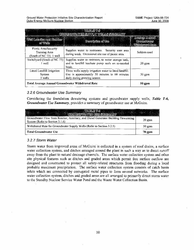
3.2.5 Groundwater Supply Wells
There are a total of six (6) groundwater supply wells at the McGuire site. A brief description ofthese wells and their usage is presented in Table T-5, Groundwater Supply Wells Summary.These wells supply water on a periodic basis to remote locations and for seasonal irrigation. Asshown in Table T-5, Groundwater Supply Wells Summary, the average annual groundwaterwithdrawal rate from these wells is 50 gpm.
9
Ground Water Protection Initiative Site Characterization ReportDuke Enerav McGuire Nuclear Station
S&ME Project 1264-06-724June 30. 2008June 30 2008
Picnic Area/SecurityTraining Area
(South of NC 73) 1 well
Supplies water to restrooms. Security uses areaduring week. Occasional site use of picnic area.
Seldom used
Switchyard (South of NC 73) Supplies water to restroom, to water storage tank,1 well and to landfill leachate pump seals on as-needed 20 gpm
basis.Lined Landfill Irrigation Three wells supply irrigation water to lined landfill.
System Use is approximately 30 minutes to 60 minutes 30 gpm3 wells daily during growing season.
Total Average Annual Groundwater Withdrawal Rate 50 gpm
3.2.6 Groundwater Use Summary
Considering the foundation dewatering systems and groundwater supply wells, Table T-6,Groundwater Use Summary, provides a summary of groundwater use at McGuire.
"rounawater rlow rrom Keactor, Auxulary, ano iilesei uienerator onUiaing LvewateringSystem (Refer to Section 3.1.6) 20 gpm
Withdrawal Rate for Groundwater Supply Wells (Refer to Section 3.2.5) 50 gpm
Total Groundwater Use 70 gpm
3.2.7 Storm Water
Storm water from improved areas of McGuire is collected in a system of roof drains, a surfacewater collection system, and ditches arranged around the plant in such a way as to direct runoffaway from the plant to natural drainage channels. The surface water collection system and othersite physical features such as ditches and graded areas which permit free surface outflow aredesigned and constructed to protect all safety-related structures from flooding during a localprobable maximum precipitation. The surface water collection system consists of catch basininlets which are connected by corrugated metal pipes to form several networks. The surfacewater collection system, ditches and graded areas are all arranged to primarily direct storm waterto the Standby Nuclear Service Water Pond and the Waste Water Collection Basin.
10

Ground Water Protection Initiative Site Characterization ReportDuke Energv McGuire Nuclear Station
S&ME Project 1264-06-724June 30. 2008
4.0 OVERVIEW OF STATION HYDROGEOLOGIC SETTING
4.1 Regional Physiographic Province
McGuire Nuclear Station is located in the Piedmont physiographic province (Figure F-i). ThePiedmont province lies between the Coastal Plain province to the east and the Blue RidgeMountain province to the west. The boundary between the Piedmont and Coastal Plainprovinces is the "fall line" - the zone where the soft sedimentary rocks of the Coastal Plain giveway to the harder, crystalline rocks of the Piedmont. The boundary between the Piedmont andBlue Ridge is the Blue Ridge scarp - a prominent topographic feature varying from about 1200 to2500 feet high in the upper drainages of the Catawba-Wateree system.
Elevations of the Piedmont province range from 220 to 600 feet in the eastern portion of thePiedmont and gradually rise to the west to about 1500 feet at the foot of the Blue Ridge scarp.Gently rolling, well-rounded hills and long low ridges underlain by saprolite developed oncrystalline rocks characterize the Piedmont province. Local relief ranges up to about 200 feet.Mountainous remnants of erosion resistant rock stand above the rolling surfaces.
The vegetation of the Piedmont shows the impact of man's activities on the land. Severalcenturies of logging, farming, grazing, and increasing urbanization have converted a onceforested landscape into patches of pine and deciduous forest mixed with fields in varying kindsof cultivation and in varying stages of abandonment.
Uil ILWp Im~al
* U1pur festal Plate*M Inur bule Plate
LiConmim 181106 +SENSE
I n.
Figure F-IPhysiographic Provinces of North Carolina(www.ncgia.ucsb.edu)
11

Ground Water Protection Initiative Site Characterization Report S&ME Project 1264-06-724Duke Energy McGuire Nuclear Station June 30, 2008
4.2 Regional Geology
The rocks of the southern crystalline Appalachians are divided based on similar rock types,structures, and aerial distribution into parallel geologic belts oriented in a southwest to northeastdirection. From northwest to southeast the geologic belts crossing the Catawba-Watereedrainage basin are: Blue Ridge, Chauga, Inner Piedmont, Kings Mountain, Charlotte, andCarolina Slate belts. McGuire Nuclear Station is located in the Charlotte belt (Figure F-2).
'- • INLXU(AI STAT'IV4
-* or'nd 1wt w- (S'm R %ert
VQ- S&.0'ta." 04unalft kedMar~ancsb - tCroA SmU kt
__- • Wo•.*a~MulFig Kre F-2Gelotabi Belt46-t far of Thasek amhb o
- T~i orfty gk TESol"3dub- h1.ATr*.1gc 3L&-bksiSub -£tora~ Trinsak &,b-Ouiu,
Figure F-2Geologic Belts of the Carolinas
The predominant rocks of the Charlotte belt are schists and gneisses of the amphibolitemetamorphic facies intruded by a complex sequence of plutonic rocks. The plutonic rocks areextensive and compositions include granite, diorite, monzonite, gabbro, norite, and pyroxenite.The general structure of the belt is primarily a function of plutonic contacts.
4.3 Regional Hydrogeology
The hydrogeology of the Piedmont region is different from and has to be considered in adifferent way from conventional sedimentary aquifer systems (LeGrand, 1988). LeGrand (1988,1989) has developed a conceptual groundwater model for the Piedmont Province (Figure F-3).
12

Ground Water Protection Initiative Site Characterization ReportDuke Enerqv McGuire Nuclear Station
S&ME Project 1264-06-724June 30. 2008
REG OLITH R,
Z0 noto
ZONE
FRACTURED BEDROCK
SAPROLITE
VVEATHERE0BEDROCK,BOULDERS
UNWVEATIHE RE DBEDROCK
Sl1EET JOIN1T"
BEDROCKSTRUCTURE
FRACTURE
Figure F-3Principle Components of Groundwater System in Piedmont Geologic Province(LeGrand, 2004)
In the Piedmont region, a thoroughly weathered and structureless material termed residuumoccurs near the ground surface with the degree of weathering decreasing with depth. Theresiduum grades into a coarser-grained material that retains the structure of the parent bedrockand is termed saprolite. Beneath the saprolite, partially weathered bedrock occurs with depthuntil sound bedrock is encountered. This mantle of residual soil, saprolite, and weathered rock(regolith) is a special hydrogeologic unit that covers and crosses various types of rock (LeGrand,1988). It provides an intergranular medium through which the recharge and discharge of waterfrom fractured rock commonly occurs. A transition zone at the base of the regolith is present inmany areas of the Piedmont (Harned and Daniel, 1989). In this zone the unconsolidated materialgrades into the bedrock. It consists of partially weathered bedrock and lesser amounts ofsaprolite. This zone may serve as a channel for rapid movement of groundwater toward thedischarge points.
The fractured nonporous bedrock is the most abundant lithologic unit underlying the Piedmontregion (LeGrand,1988). It includes many different types of igneous and metamorphic rocks.The fractures control both the hydraulic conductivity and the storage capacity of the rock mass(Trainer, 1988). Fractures tend to be more extensive and permeable in homogenous aluminum-deficient rocks than in micaeous rocks (Randall and others, 1988). The latter are less brittle andtheir weathering products have a high clay content that tends to reduce fracture permeability(Randall and others, 1988). Fracture permeability tends to be greater in alkalic igneous rocks(granites/quartz diorites) than in calcic igneous rocks (gabbros/ultramafics/diorites) because
13

Ground Water Protection Initiative Site Characterization Report S&ME Project 1264-06-724Duke Energy McGuire Nuclear Station June 30, 2008
potassium and sodium-rich feldspars tend to produce about half as much clay as calcium-richfeldspars (Randall and others, 1988).
Groundwater occurs within the pore space of the residuum/saprolite and within fractures of theunderlying bedrock. The residuum/saprolite is capable of storing water readily, but transmits itslowly. In contrast, the bedrock fracture system has a relatively low storage capacity but iscapable of transmitting water readily where interconnecting fractures occur (LeGrand, 2004).The transition zone characteristics will exist between the two, but will commonly store andtransmit groundwater readily. The hydraulic connection between the residuum/saprolite mediumand bedrock medium will depend on the characteristics of the transition zone, a function ofrock/soil type, amount of weathering, and degree (location/frequency) of fracturing within thebedrock.
LeGrand's (1988, 1989) conceptual model of the groundwater setting in the Piedmontincorporates the above two medium system into an entity that is useful for the description ofgroundwater conditions. That entity is the surface drainage basin that contains a perennialstream (LeGrand, 1988) (Figure F-3).
ARROWS SHOW 01ACCTION OF
"a SATURATED
> ___ < ~ ZONE
SHEET ýE OF FR ACTURE
Figure F-4Conceptual Groundwater Flow System in Piedmont Geologic Province(LeGrand, 2004)
Each basin is similar to adjacent basins and the conditions are generally repetitive from basin tobasin. Within a basin, movement of groundwater is generally restricted to the area extendingfrom the drainage divides to a perennial stream (Slope-Aquifer System; LeGrand, 1988, 1989).Rarely does groundwater move beneath a perennial stream to another more distant stream(LeGrand, 1989).
Therefore, in most cases in the Piedmont, the groundwater system is a two medium system(LeGrand, 1988) restricted to the local drainage basin. The groundwater occurs in a systemcomposed of two interconnected layers: residuum/saprolite and weathered rock overlyingfractured crystalline rock. Typically, the residuum/saprolite is partly saturated and the watertable fluctuates within it. Water movement is generally through the fractured bedrock. The
14

Ground Water Protection Initiative Site Characterization Report S&ME Project 1264-06-724Duke Energy McGuire Nuclear Station June 30, 2008
near-surface fractured crystalline rocks can form extensive aquifers. The character of suchaquifers results from the combined effects of the rock type, fracture system, topography, andweathering. Topography exerts an influence on both weathering and the opening of fractures,while the weathering of the crystalline rock modifies both transmissive and storagecharacteristics.
Groundwater will migrate from areas of high hydraulic pressure, or recharge areas, to areas oflow hydraulic pressure, or areas of discharge, through the pore space of the soil and throughfractures in the bedrock. Typically in the Piedmont, topographically high areas (hilltops)correspond to recharge areas and topographically low areas (valley streams) correspond todischarge areas. The direction of groundwater flow is determined by the hydraulic gradient. Therate of groundwater movement in the saprolite is a function of the gradient, the hydraulicconductivity of the soil, and the effective porosity (a measure of the pore space interconnection).The rate of groundwater movement in the bedrock, although influenced by gradient, is mostdependent upon the hydraulic conductivity and interconnectedness of the fracture system.Complex local geologic conditions cause wide differences in rates of flow, ranging from greaterthan one foot per day to less than one foot per century (LeGrand, 2004).
4.4 Site Geology
The physiography of the site is typical of that of the surrounding Piedmont Geological Province.The four major rock types appearing at the site are dark green meta-gabbro, light gray fine tomedium grained granite, black and white fine grained diorite, and black and white coarse graineddiorite. An examination of the rock cores at the site generally confirms the published geologicliterature of the placement order and relative age of the rock types at the site and the previousfindings of the UFSAR.
The geologic structure of the site is very old and complex. Due to the various episodes ofigneous intrusions, the site area is typified by bodies of the various rock types highly interlayedboth horizontally and vertically. Several minor shear zones, including slickensided surfaces,were noted in the core borings at the site both during this investigation and during the UFSARinvestigation. An ancient flood plain or high level terrace, probably of the Catawba River, existsin the higher portions of the site.
The geologic history of the site is typical of that of the region. During the middle to latePaleozoic time, there were several periods of intrusion of granite and diorite which left onlysmall amounts of the parent rock, meta-gabbro and mica schist, in the Charlotte Belt includingthe site area. The slickenside surface at the site was caused during one of the last episodes ofintrusion. The last intrusive activity in the area was in the form of Triassic diabase and othermafic dikes like the one found at the site during previous studies for the UFSAR.
4.5 Site Groundwater
Groundwater recharge in the Piedmont province is derived entirely from infiltration of localprecipitation. The surface materials in many locations are relatively impermeable, with the resultthat only 10 in. (25 cm) to 15 in. (38 cm) of the average 43 in. (108 cm) of annual precipitationpercolate to the water table (UFSAR).
15

Ground Water Protection Initiative Site Characterization Report S&ME Project 1264-06-724Duke Energy McGuire Nuclear Station June 30, 2008
During McGuire site development, groundwater was generally encountered under water tableconditions in the residual soil/saprolite and weathered rock that overlie less weathered rock.Preconstruction groundwater elevation along the northern boundary of the site coincides with theelevation of the surface of Lake Norman, and groundwater movement was generally to the southand southwest (UFSAR).
Since the bottom elevations of the structures are below the natural water table, McGuireconstruction incorporated foundation dewatering systems beneath the Reactor Building area tolower the water table. This underdrain system remains in service and results in a minimumgroundwater level of about elevation 712 in the Reactor Building area and a depression of thewater table with groundwater flow towards the Reactor Building and Auxiliary Building areafrom the northeast and west. Largely founded within the levels of weathered rock and bedrock,it was expected during development of this Ground Water Protection Initiative scope that thefoundation dewatering systems of these buildings would have an impact on groundwater flow.
4.5.1 Site Hydrostratigraphic Units
Given (1) knowledge of the McGuire site from the UFSAR description and (2) experience in thePiedmont Geologic province, the following hydrostratigraphic units were selected for sitecharacterization use on this project:
1. Fill (F) - Embankment material that has been either dumped or sluiced into place.2. Alluvium (S) - Material deposited by stream action and consisting mainly of sandy silts
and silty sands.3. Soil/Saprolite (MI) - Soil and saprolite, primarily sandy silt and silty sand, developed by
the in-place weathering of the underlying bedrock with Standard Penetration Resistanceof N<100.
4. Weathered Rock (M2) - Saprolite and weathered rock with Standard PenetrationResistance of N> 100 and/or Rock Core Recovery < 50%.
5. Partially Weathered/Fractured Rock (WF) - Rock with Rock Core Recovery > 50% andRock Quality Designation < 50%.
6. Sound Rock (D) - Rock with Rock Core Recovery > 85% and Rock Quality Designation> 50%.
16

Ground Water Protection Initiative Site Characterization Report S&ME Project 1264-06-724Duke Energy McGuire Nuclear Station June 30, 2008
5.0 SOURCE/SOURCE PATHWAY EVALUATION AND MONITORINGLOCATIONS
5.1 Contaminants of Interest and Their Fate in the Environment
Water containing trace amounts of various radioactive materials is normally released from U.S.nuclear power plants under controlled, monitored conditions, that meet conservative NuclearRegulatory Commission (NRC) limits to protect public health and safety. Recently, severalinstances of unintended, abnormal releases of radioactive liquids to the environment wereidentified. Materials detected to date in groundwater around nuclear power plants includeTritium and Strontium 90 (NRC, 2007). Of these two materials, Strontium-90 is only associatedwith specific, isolated plant systems, such as the Spent Fuel Pool. Tritium is much moreprevalent in plant systems than Strontium-90, and is thus considered a much better indicator ofpotential radioactive releases. As such, while Strontium-90 as a material is monitored by DukeEnergy on a specific basis, tritium and potential sources of tritium are the focus of this GroundWater Protection Initiative.
As a background, the following section provides a brief overview of the properties, sources, andoccurrence of tritium, and its fate in the environment.
5.1.1 Tritium
Tritium, H3, is a radioactive isotope of the element hydrogen. The most common form of tritiumis in water, since both radioactive tritium and non-radioactive hydrogen readily bond withoxygen to form water. Tritium replaces one of the stable hydrogens in the water molecule H20.
When this happens, the resulting water, called tritiated water (H3 HO or HTO), is radioactive.Tritiated water (not to be confused with heavy water) is chemically identical to normal water,i.e., colorless and odorless, and the tritium cannot be filtered out of the water (EPA, 2007; NRC,2006, 2007).
Tritium is formed by natural and man-made processes. Tritium' occurs naturally in the upperatmosphere when cosmic rays strike air molecules. It is also produced during nuclear weaponsexplosions, and commercially in nuclear reactors producing electricity. Most of the tritiumproduced in an electrical power reactor is as a byproduct of the absorption of neutrons by boron,which nuclear reactors use to help control the fission chain reaction (EPA, 2007; NRC, 2006,2007).
Tritium that is formed in the atmosphere enters the groundwater as precipitation recharge.Tritium was produced by thermonuclear explosions that took place in the atmosphere, primarilybetween 1952 and 1969 (Drever, 1988). Tritium levels in rainwater are expressed as TU, tritiumunits'. Although few tests were made prior to atmospheric testing, the natural occurringconcentration of tritium in rainwater prior to atmospheric testing was taken to be about 10 TU.During the peak of atmospheric testing, in the 1960's the levels rose significantly, approaching103 TU. Current values of tritium in rainwater are around 10 TU [Drever, 1988]. Average
1 1 TU - one tritium atom per 101 hydrogen atoms.
17

Ground Water Protection Initiative Site Characterization Report S&ME Project 1264-06-724Duke Energy McGuire Nuclear Station June 30, 2008
tritium concentrations in rainwater in Charlotte averaged 93 pCi/L for the period 1986 to 2007.[USEPA RAD NET] The US EPA equates I TU as being approximately equal to 3.2 pico Curiesper liter (pCi/L). The US EPA health standard for tritium is 20,000 pCi/L (- 6250 TU) (NRC,2006).
Tritium has a half-life of 12.3 years. As it undergoes radioactive decay, tritium emits a very lowenergy beta particle and transforms to stable, nonradioactive helium. (EPA, 2007).
5.1.1.1 Kd Values for Tritium
Since tritium readily combines with oxygen to form water, its behavior in aqueous systems iscontrolled by hydrologic processes and it migrates at essentially the same velocity as surfacewater and groundwater. Sorption processes are therefore not expected to be important relative tothe movement of tritium through aqueous environments. Typically, a partition coefficient, Kd,of 0 ml/g is used to model the migration of tritium in soil and groundwater environments. (EPA,1999).
5.2 Structures, Systems and Component Evaluation
Duke Energy staff from multiple plant disciplines, including Radiation Protection, Environment,Health and Safety, Engineering and Project Management, performed an evaluation of potentialradiological (tritium) sources at McGuire. This evaluation consisted of a structured riskassessment as well as a review of relevant plant operating experience.
5.2.1 Risk Assessment Process
In order to focus on potential contaminated sources and source pathways to groundwater, a riskassessment was performed on the plant structures, systems and components (SSC). This riskassessment took into consideration four distinct aspects of these SSC and the environment inwhich they are located. The four distinct aspects are the hydro-geologic profile, the volumeprofile, the tritium profile and the engineering profile.
For the hydro-geologic profile, a value was assigned to the SSC based on the ease with whichany liquid, contained within or directed by it, could reach groundwater. For example, a highervalue was given to an SSC if no difficulty existed for any liquid, contained within or directed byit, to reach groundwater should a failure or leak occur. An example here is a buried pipe whereits contents could easily reach groundwater if the contents escaped. In contrast, a component orsystem inside a building with lined sumps would receive a low ranking, since there would belittle to no opportunity for any escaped contents to reach groundwater.
A similar ranking philosophy was used for the other profiles. For the volume profile, the amountof contained liquid volume determined the risk ranking. A higher volume equaled a higher riskranking value. Large pipes and tanks received a higher volume profile ranking. For the tritiumprofile, the tritium concentration determined the risk ranking. Known tritium sources such as thespent fuel pool and several process water tanks containing radioactive liquids received highertritium values.
18

Ground Water Protection Initiative Site Characterization Report S&ME Project 1264-06-724Duke Energy McGuire Nuclear Station June 30, 2008
For the engineering profile, the materials of construction, known aging issues and physicallocation that could affect the ability to inspect and maintain the SSC were included in theengineering profile logic. For example, a higher engineering profile risk ranking was given toburied piping and tanks.
The risk assessment algorithm consisted of multiplying the four independently determinedprofile values to establish an overall groundwater risk profile. The latter two profiles, the tritiumprofile and the engineering profile, were given more weight in this risk assessment than theformer two. The final groundwater risk profile resulted in a rank ordering of plant SSC withthose higher on the list considered to be more "risky" and thus of higher importance to theGround Water Protection Project. Section 5.2.2 contains a summary of the plant SSC of higherimportance for the purposes of this investigation.
5.2.2 Risk Assessment Results
In summary, the following plant structures, systems or components (SSC) emerged as exhibitinga higher risk of contributing unmonitored releases of tritium to the environment:
* Conventional Wastewater Treatment (WC) Ponds, including Initial Holdup Pond,Pond A, Pond B and the Final Holdup Pond.
* Waste Water Collection Basin* Standby Nuclear Service Water Pond* Auxiliary/Reactor Building SSC, including
o Spent Fuel Pools, Unit 1 and Unit 2o Refueling Canals, Unit 1 and Unit 2o Waste Evaporator Feed Tank Sumps
* Radwaste Facility Building Sump* Landfarms #1 and #2* Landfill #1
Further details on the groundwater risk profile for these and all relevant SSC considered in thisinvestigation are contained in Appendix B.
5.2.3 Operating Experience
In addition to the structured risk assessment of plant SSC, a review of operating experience wascompleted as part of the overall project investigation. The operating experience results wereincluded in a letter dated August 3, 2006, from James R. Morris, Duke Energy, to the USNuclear Regulatory Commission. Specific occurrences of inadvertent releases of radioactiveliquids that had the potential to reach groundwater were noted as follows:
Events listed below are those which have been documented in accordance with 10 CFR50.75(g) and had potential to reach groundwater; however, an actual release to groundwatermay not have occurred.
19

Ground Water Protection Initiative Site Characterization Report S&ME Project 1264-06-724Duke Energy McGuire Nuclear Station June 30, 2008
* March 1987Contaminated soil was recovered from a Unit 1 reactor make-up water storage tank(RMWST) rupture.
S7/10/1992
Soil and sludge were recovered as a result of a water spill in the area between Unit 2refueling water storage tank (FWST) and the shield wall. The water was discharged intoa spillway between standby nuclear service water pond (SNSWP) and the waste watercollection basin (WWCB).
* 9/14/1998A leak occurred from Unit 1 reactor coolant drain tank (NCDT) through hydrogenstorage (GB) instrument lines (1GB-9) into Unit 1 turbine building basement.
* 6/26/2003Tritium was identified in the Groundwater Drainage System (WZ) sump. This systemcollects the groundwater drainage from under the site and channels it into the WZ sumps.The effluent from these sumps is composited and analyzed monthly.
* 6/17/2004Documentation of tritium concentration which was greater than baseline values in two(2) temporary monitoring wells west of conventional waste (WC) holdup ponds.
* 6/7/2004Contamination was discovered in the pipe trench between the radwaste facility and thesolidification pad.
This operating experience was also factored into the selection of additional monitoring well
locations as discussed in Section 5.3.3.
5.3 Groundwater Protection Monitoring Well Location Selections
Locations and depths of the new groundwater protection monitoring wells were selected basedon considering a collaboration of information and goals. Information available for the selectionprocess comprised the following:
" Plant structures, systems and components (SSC) considered primary potential sources oftritium from a structured risk assessment and from relevant operating experience (Section5.2);
" Master Conceptual Model of geology and hydrogeology in the Piedmont GeologicProvince of North Carolina (LeGrand, 2004); and,
" Knowledge of site geology and hydrogeology from the Updated Final Safety AnalysisReport (UFSAR).
20

Ground Water Protection Initiative Site Characterization Report S&ME Project 1264-06-724Duke Energy McGuire Nuclear Station June 30, 2008
Goals for the installed groundwater protection monitoring well system comprised providing thefollowing:
" An exploration scheme that would provide hydrogeologic characterization of theoperating plant site, including evaluation of the capture zone(s) of the subsurface drainsystem(s); and,
" A robust monitoring well network capable of providing early detection of tritium releases(near-field wells) and verifying no off-site migration (far-field wells).
Well locations were first spatially selected (1) in proximity to plant system tritium sources and/or(2) in nearby projected down-gradient groundwater flow directions from plant system tritiumsources (i.e., near-field monitoring locations). Spatial distribution then considered additionallocations that would (1) provide monitoring to confirm the absence of off-site migration (i.e., far-field monitoring locations) and/or (2) be helpful for site characterization. Following spatialdistribution, consideration for well depths (vertical screen intervals) was considered. Shallowerwells were utilized where shallow groundwater was expected, as first detection monitoringlocations. Shallower wells were, in cases, omitted where it was expected that subsurface drainswould have the water table depressed. Deeper wells (top of rock wells) were utilized whereplant systems were deep and founded on bedrock (e.g., Reactor Buildings, Auxiliary Buildings,and Turbine Buildings), placing the well screen (sampling interval) nearer the level of potentialtritium release. Combinations of shallow/top of rock and/or top of rock/deeper bedrock wereutilized to monitor and characterize vertical components of groundwater flow.
Final Ground Water Protection Initiative well locations were subject to plant accessibility andoverhead and underground system obstructions.
5.3.1 Existing Boring Information
In the early 1970s, Law Engineering Testing Co. prepared the Subsurface Conditions &Foundation Recommendations report for the McGuire Nuclear Station's Units 1 & 2. For record,Duke Energy requested that the Core Boring Records and Test Boring Records from the abovereport be preserved in this Ground Water Protection Initiative Site Characterization Report. Tothis end, S&ME has provided a digital (CD) record of this information in Appendix I -Historical Boring Records. Locations of borings H-1 through H-100 and W-1 through W- 11would be provided in the McGuire Preliminary Safety Analysis Report (PSAR) or other recorddocuments.
5.3.2 Existing Well Information
Early in the well location evaluation process, it was recognized that selected existing McGuirewells would be beneficial to the Ground Water Protection Initiative, these being four wellsinstalled in the area of the Power Block (M-42, M-68, M-72, and M-76), two old Landfarm #1wells (M-87 and M-89), one well installed north of the Wastewater Collection Basin (M-101),and one well installed southwest of the WC Basins (M- 102).
21

Ground Water Protection Initiative Site Characterization Report S&ME Project 1264-06-724Duke Energy McGuire Nuclear Station June 30, 2008
Locations of the eight existing Ground Water Protection Initiative monitoring wells are portrayedon Figure 4, Ground Water Protection Initiative Monitoring Wells. A summary of installationdetails for the eight existing wells is provided in Appendix C - Soil Test Boring Field Reportsand Monitoring Well Installation Records for Selected Existing McGuire Wells. Groundwatermeasurements and tritium concentrations from the above wells are considered within this report,as applicable.
5.3.3 Phase 1 Wells
Ultimately, an initial suite of 41 new groundwater protection monitoring wells (designated withthe identification prefix "M") was selected for installation at McGuire.
Outside of the protected area 27 new Ground Water Protection Initiative monitoring wells wereinstalled. There were 28 wells proposed outside of the protected area, however, location M-80was drilled to 50 feet below land surface without encountering groundwater, and therefore, nowell was installed in that location. Of the 27 wells installed outside of the protected area, 15wells were designed to monitor the shallow water table groundwater occurring in the saprolite(and have no suffix to their designation); 10 were designed to monitor the groundwater occurringin the transition zone of highly fractured bedrock (and have the suffix "R"); and two weretargeted to monitor groundwater present in the deeper less fractured/weathered bedrock (andhave the suffix "DR").
Within the protected area, 13 monitoring wells were installed. Of the 13 wells located within theprotected area, eight were targeted to monitor the shallow water table groundwater occurring insaprolite (and have no suffix to their designation); three were targeted to monitor groundwateroccurring in the transition zone of highly fractured bedrock (and have the suffix "R"); and twowere targeted to monitor groundwater present in the deeper less fractured/weathered bedrock(and have the suffix "DR").
Locations of the 40 Phase 1 Ground Water Protection Initiative monitoring wells are portrayedon Figure 4, Ground Water Protection Initiative Monitoring Wells. A summary of installationdetails for the 40 Phase 1 wells is provided in Table 1, Monitoring Well ConstructionSummary.
5.3.4 Phase 2 Wells
Duke Energy selected 11 additional well installation locations for Phase 2 work. Six locationswere selected on the south side of North Carolina Highway 73 (NC-73) to fill in data gaps for thesite characterization groundwater model. In response to tritium levels detected in the newlyinstalled monitor well M-33 on the east side of the McGuire access road near NC-73, DukeEnergy selected two additional groundwater monitoring well installation locations to assess thehorizontal extent of tritium detected in well M-33. In response to tritium levels detected downgradient of the WC Basins, Duke Energy selected two additional groundwater monitoring wellinstallation locations up gradient of the WC Basins to assess the horizontal and vertical extent oftritium detected. Also part of Phase 2 was the installation of monitoring well M-60 whichreplaced existing well W-26.
22

Ground Water Protection Initiative Site Characterization Report S&ME Project 1264-06-724Duke Energy McGuire Nuclear Station June 30, 2008
Locations of the 11 Phase 2 groundwater protection monitoring wells are portrayed on Figure 4,Ground Water Protection Project Monitoring Wells. A summary of installation details for the11 Phase 2 wells is provided in Table 1, Monitoring Well Construction Summary.
5.3.5 Surface Water Sampling Locations
Duke Energy selected four surface water sampling points to be included in the Ground WaterProtection Initiative at McGuire (MS-1, MS-2, MS-3, and MS-4). These surface water samplingpoints are natural springs located between the Power Block and the Catawba River.
Locations of the four surface water sampling points are portrayed on Figure 4, Ground WaterProtection Initiative Monitoring Wells.
23

Ground Water Protection Initiative Site Characterization Report S&ME Project 1264-06-724Duke Energy McGuire Nuclear Station June 30, 2008
6.0 REGULATORY APPROVALS AND DOCUMENTATION
S&ME submitted a Subsurface Investigation Application and Permit to the North CarolinaDepartment of Environmental and Natural Resources (Department) for the groundwatermonitoring wells to be installed at McGuire Nuclear Station. A copy of the application isincluded in Appendix D.
In accordance with permit conditions, S&ME periodically submitted completed and signed Nonresidential well construction records (GW-1B) forms to Mecklenburg County Health Departmentand the NCDENR as selected sets of wells were constructed and surveyed. A copy of the five(5) Non-Residential Well Construction Records - Submittals 1, 2, 3, 4, and 5 are included forreference and record in Appendix D.
24

Ground Water Protection. Initiative Site Characterization Report S&ME Project 1264-06-724Duke Energy McGuire Nuclear Station June 30, 2008
7.0 FIELD METHODS FOR GROUNDWATER MONITORING WELLINSTALLATIONS
The following text provides a general overview of field methods utilized for groundwatermonitoring well installations. Note that deviations from the general procedures discussed were,in instances, dictated by field conditions.
7.1 Preliminary Well Locations
Preliminary well locations were initially spatially estimated on site plans considering acollaboration of information including potential tritium sources, existing groundwater monitoringwell locations, the Final Safety Analysis Report (UFSAR), and Piedmont Geologic Provincegeology. Vertical distribution, i.e., shallow wells, well pairs, and/or well triplets, weresubsequently selected. Station and/or state plane coordinates of the initially selected welllocations were identified and the locations were marked in the field on the ground using GlobalPositioning System (GPS) technology.
7.2 Utility Clearance and Final Well Locations
Duke Energy engineering and surveying personnel reviewed the initially selected well locationsversus existing site plans with underground utility information and conducted undergroundutility surveys. Duke Energy surveyors identified an approximate 10 foot by 20 foot work area(room for drill rig access and orientation) in the vicinity of each initially selected well locationthat was free of underground and overhead interferences. They marked the clear work area onthe ground in the field and surveyed its plant coordinates. Duke Energy utilized the surveyedwork area to complete the plant modification package for the final well installations to occurwithin the cleared work areas.
7.3 Plant Access Training, Mobilization, Safety Orientation, and Security Access
Duke Energy and S&ME had coordinated personnel plant access training (PAT) earlier in thenuclear fleet project (2006). Duke Energy and S&ME coordinated mobilization of personnel,equipment, supplies, and materials to McGuire Nuclear Station on March 19, 2007. Safetyorientation and security access occurred on March 20, 2007.
7.4 Soil Test Borings, Soil Classification, Soil Testing
S&ME began soil test borings for well installations on March 21, 2007. Soil test borings weregenerally drilled into the residual soil/saprolite using 4¼-inch inside diameter (nominal 8¼/4outside diameter) hollow-stem augers and/or mud-rotary drilling using NW casing fronted with anominal 4 7/8-inch diameter roller cone bit. Split-spoon sampling (ASTM D1586) was utilizedto sample soils at approximate 5-foot intervals. Drilling and soil sampling at single welllocations was advanced to a depth of approximately 50 feet below ground surface; exceptionsincluded shallower auger refusal depths or groundwater encountered deeper than 50 feet belowground surface. Drilling and soil sampling at multiple well locations was continued to augerrefusal.
25

Ground Water Protection Initiative Site Characterization Report S&ME Project 1264-06-724Duke Energy McGuire Nuclear Station June 30, 2008
Soil samples were photographed and visually classified in the field by the on-site geologist fororigin, consistency/relative density, color, and soil type in accordance with the Unified SoilClassification System (ASTM D2487/D2488). A selected distribution of the soil samples (i.e., F,S, Ml, M2) from across the site were transferred to S&ME's soil laboratories for grain sizedistribution (ASTM D422) and specific gravity testing (ASTM D854) to support estimation ofsoil porosity for groundwater flow rate calculations and modeling.
Soil Boring Logs portraying drilling depth, soil sample depths, blow counts (N-values), and soilclassifications are included in Appendix E, arranged by well location. Also included arephotographs of split-spoon soil samples, arranged by well location, for reference and record. ALegend to Soil Classifcations and Symbols is included for reference.
7.5 Rock Coring and Classification
For the borings advanced into bedrock, drilling was continued with NQ (nominal 3-inchdiameter) rock coring techniques (ASTM D2113) below auger/roller cone refusal. In general, aminimum of 20 feet of rock was cored at each rock well location for visual and manualclassification. More rock was cored depending on fracture locations, groundwater level, and ifadditional depth was required for screen separation.
The on-site geologist photographed and visually classified the rock samples for color,weathering, fracturing, and rock type in accordance with Field Guide for Rock Core Logging andFracture Analysis (Midwest Geosciences). Percent recovery and Rock Quality Designation(RQD) were calculated for each rock core interval.
Soil Boring Logs portraying rock core intervals, percent recovery, RQD, and rock classificationsare included in Appendix E, arranged by well location. Also included are Rock Core Logspresenting a graphical presentation of the rock coring interval and photographs of the rock coresamples, arranged by well location, for reference and record.
7.6 Permeability and Packer Testing
Open-hole falling head (OHFH) permeability tests and packer tests were conducted in the soilboreholes/rock coreholes and rising head permeability tests (slug tests) were performed in thecompleted monitoring wells. The goal of the in-situ permeability testing was to obtain arepresentation of the permeability/hydraulic conductivity across and within the varioushy'drostratigraphic units.
OHFH permeability tests were conducted at selected intervals in the soil/saprolite (Ml) and/orweathered rock (M2) hydrostratigraphic units (above auger/roller cone refusal). The OHFHpermeability tests in the soil/saprolite comprised drilling to the desired depth, removing drillingtools (as applicable), inserting and seating NW casing to the bottom of the borehole, andadvancing a 2 15/16 roller bit 3± feet below the casing. The extended borehole and casing werethen filled with water. The rate of water loss/seepage with time was measured using a pressuretransducer and data-logger. Open-borehole permeability was computed from the raw field datawithin Excel computation sheets.
26

Ground Water Protection Initiative Site Characterization Report S&ME Project 1264-06-724Duke Energy McGuire Nuclear Station June 30, 2008
OHFH permeability tests were conducted at selected intervals in the partiallyweathered/fractured rock (WF) and sound rock (D) hydrogeologic units below auger/roller conerefusal. The OHFH permeability tests below refusal were generally conducted at the followinglocation levels:
• One test within the first core interval (generally 5 feet or less); and,• One test within the first and second core intervals combined (generally 10-feet or less).
The OHFH permeability tests in the partially weathered/fractured rock and sound rock comprisedcoring to the desired depth and removing the core barrel. The NW casing was left in place,seated at the top of rock. The corehole and casing were then filled with water. The rate of waterloss with time was measured using a pressure transducer and data-logger. Open-boreholepermeability was computed from the raw field data within Excel computation sheets.
Packer tests were performed within field selected corehole locations. Generally, two packer testsper boring were performed at intervals and pressures selected in the field by the on-site geologist.Intervals and pressures were selected based on in-situ corehole conditions (weathering,fracturing, etc.) and groundwater presence with the objective of evaluating groundwatermovement in rock. Packer testing comprised testing a 5-foot incremental section of corehole, bylowering the packer assembly into the corehole to the predetermined depth. The packers werethen pressurized and seated to seal the off the 5-foot interval to be tested.
The packer tests were conducted at three different effective pressures specified in the field by theon-site geologist. The test was started at the lowest pressure and advanced incrementally to themaximum allowable pressure, after which the pressure was reduced by the same decrements tothe initial starting pressure. The total water intake in tenths of gallons for specified timeintervals at each pressure was measured by a flowmeter. Permeability was computed from theraw field data within Excel computation sheets.
Open-hole falling head and packer test permeability data and calculations are provided inAppendix E, arranged by well location.
7.7 Well Construction
Monitoring wells were constructed of 2-inch I.D., NSF Grade PVC (meeting ASTM D-178S andF480) Schedule 40 flush-joint threaded casing and 0.01-inch machine slotted screen. Once theborehole/corehole was drilled, the on-site geologist selected the monitor depth(s) and approved themonitoring well construction based on site-specific hydrogeologic conditions and the followinggeneral criteria:
1. For shallow monitoring wells located above refusal, the saprolite groundwater monitoringwell screen intervals were generally 15 feet in length and located so that the stabilizedwater table intersected the screen interval with approximately 10 feet of screensubmerged beneath the water table. In areas where relatively shallow groundwater levels(i.e., less than 5 feet below land surface) were encountered, the top of the screen wasplaced at a depth of approximately 5 feet below land surface to allow adequate seal and toallow sufficient grout and concrete collar to secure the protective casing.
27

Ground Water Protection Initiative Site Characterization Report S&ME Project 1264-06-724Duke Energy McGuire Nuclear Station June 30, 2008
If the bottom of the shallow monitoring well's screened interval was located above theborehole termination depth, the interval below the screen elevation and bottom of boringwas sealed using pelletized bentonite.
The annular space between the borehole wall and the well screen was backfilled with clean,well rounded, washed, high grade #1 silica sand. The sand pack was placed toapproximately two feet above the slotted screen. At I- to 2-foot pelletized bentonite sealwas placed above the filter pack. The remainder of the annular space was filled with acement/bentonite grout (neat cement) from the top of the bentonite seal to near groundsurface.
2. For wells with their screen interval located below auger/roller cone refusal, the screeninterval was selected based on in-situ conditions of the bedrock [e.g., most apparentgroundwater bearing fracture(s)] and maintaining a separation interval (e.g., 20± feet)between adjacent shallow and deep monitor intervals. Well screens were generally 5 feet inlength unless greater screened intervals were deemed necessary by the on-site geologist toallow more fractures to intersect the screened interval
If the bottom of the monitoring well's screened interval was located above the coreholetermination depth, the interval below the screen elevation and bottom of boring was sealedusing pelletized bentonite and capped with a minimum 1-foot thick sand layer.
For the majority of the deep wells, no sand pack was placed within the annular spacebetween the corehole and screen. To seal the monitored interval, a rubber k-packer assembly(manufactured by Western Rubber & Mfg., Part KPRR23, 2"X3" coupling) was installedabove the screen which uses three rubber ribs to form a seal between the corehole andcasing. To further reinforce the seal, an approximately 1- to 2-foot thick granular bentonitelayer was placed above the k-packer. The remainder of the annular space was filled with acement/bentonite grout (neat cement) from the top of the bentonite seal to near groundsurface.
For the deep wells that did not use a k-packer, a Type III well was installed with a 6-inchouter casing installed to the top of rock and grouted in place. The annular space between thecorehole wall and screen was backfilled with #2 filter sand. Generally a 2-foot pelletizedbentonite seal was placed above the filter pack. The remainder of the annular space wasfilled with a cement/bentonite grout (neat cement) from the top of the bentonite seal to nearground surface.
Based on well location and McGuire requirements, either a 4" x 4" x 5' Enco Wheaton or a 6" x 6"x 5' Drilling Services, Inc. (DSI) steel protective casing with a locking cap, or an 8-inch steelmanhole manufactured by IES Drilling Supplies, cast iron with Buna rubber seals was installed overthe well's riser pipe. If a protective casing was installed, then it was sealed and immobilized in aconcrete collar placed around the protective casing. The 6" x 6" x 5' DSI protective casing wasused for Type III monitoring well installations. If a manhole was installed, in accordance with theDepartment's variance approval, the manhole was seated in a pea gravel collar to allow for drainage
28
Ground Water Protection Initiative Site Characterization Report S&ME Project 1264-06-724Duke Energy McGuire Nuclear Station June 30, 2008
of surface water away from the wall of the casing if it penetrates the manhole seal. Both protectivecasings and manholes were completed with a 2-foot square concrete pad sloping gently away fromthe well in all directions and inscribed with the well's identification number.
Each well location was affixed with a permanent well tag which includes at a minimum thefollowing information:
" Well identification number;" Driller registration number;• Total depth of well;" Depth of screen interval;" Depth to groundwater following well completion; and," A warning that the well is not for water supply and that the groundwater may contain
hazardous materials.
Well Logs presenting a graphical depiction of well construction details are included in AppendixE, arranged by well location.
7.8 Well Development
Following well installation, the monitoring wells were developed in order to remove clay, silt, sandand other fines which may have been introduced into the formation or sand pack during drilling andwell installation, and to establish communication of the well with the aquifer. Well developmentwas performed using a portable well pump and was performed as soon as possible after wellconstruction. Development pumping continued until the water being removed was relatively clearand sediment free. At a minimum, 5 well volumes of water were pumped from the wells.
7.9 Slug Testing
Following monitoring well installation and development, slug tests were performed in each newgroundwater monitoring well to evaluate the horizontal permeability or hydraulic conductivity ofthe subsurface materials surrounding the saturated portion of the screened interval. Slug tests wereperformed by removing a field specified amount of water from the well using a portable wellpump. The well was then allowed torecharge as measurements of increasing water level withtime were recorded using a pressure transducer and data logger. Rising head permeability wasthen computed from the field data using the Bouwer and Rice Graphical Method.
Slug test data and computations are included in Appendix E, arranged by well location.
7.10 Equipment Cleaning and Investigative Derived Waste Management
Prior to initial drilling activities, down-hole equipment was cleaned with high pressure hot waterand allowed to dry. Cleaning was performed similarly between each soil test boring location.
During McGuire drilling activities, soil cuttings outside the Protected Area'(PA) were spread ingrassy areas on-site, while soil cuttings inside the PA were contained until Duke Energy'sRadiation Protection (RP) group performed radiological testing and cleared soil for disposal.Inside the PA, soil was temporarily contained in a steel mud tub during mud rotary drilling, and
29

Ground Water Protection Initiative Site Characterization Report S&ME Project 1264-06-724Duke Energy McGuire Nuclear Station June 30, 2008
in a Bobcat® bucket during auger drilling. Composite soil samples were collected by S&MEevery 25 feet in soil borings until refusal was achieved. RP retrieved the samples from S&MEfor on-site analysis. Drilling operations were temporarily halted while on-site analysis wasperformed. Drilling activities continued after receiving verbal confirmation from RP.Ultimately, soil cuttings and drilling fluids collected in the mud tub or Bobcat® bucket weredeposited into a roll-off filter container. Filter container soil was disposed of at the on-siteMcGuire Landfill.
Email documentation of soil transport and disposal are included in Appendix F.
Water generated from field activities such as rock core water, development water, and in-situtesting water, was allowed to filter through bails of wheat straw before entering yard drains.
7.11 Groundwater Monitoring Well Location Survey
Duke Energy surveyors surveyed the horizontal and vertical control locations of all newlyinstalled Ground Water Protection Initiative monitoring wells. Additionally, Duke Energyprovided survey documentation of the existing monitoring wells on site. Horizontal control isprovided relative to North Carolina Grid NAD 83 and Plant Grid; vertical control is providedrelative to NGVD 29. Survey documentation is duplicated in Table 1.
7.12 Groundwater Sample Collection
Duke Energy conducted Ground Water Protection Initiative sampling events concurrently withdrilling activities in April 2007, May 2007, June 2007, August 2007, November 2007, andJanuary 2008. The first and only synoptic (including all groundwater protection wells) samplingevent to date was conducted in February 2008. Data obtained from the February 2008 samplingevent is used in this report for tabulation and calculation purposes.
Sampling and purging equipment are chosen to ensure the material making up the equipment arecompatible with the sample parameters and also comply with state and federal regulatoryrequirements for sampling. Samples are collected in accordance with Duke Energy Procedure3175.0; Procedure for Groundwater Monitoring and Sample Collection, February 2006.
Groundwater for Duke Energy's Nuclear Ground Water Protection Initiative is collected by"Low Flow/Low Energy" methodology. Samples are collected using pneumatic bladder pumpsand dedicated tubing. However, three wells are sampled using a peristaltic pump rather than apneumatic pump (M-87, M-89, and M-72). M-87 and M-89 are old Landfarm wells in whichhistorical pumping methods were continued, and M-72 is a 12-inch geoprobe well. For all wells,pumps are placed near the middle of the wetted well screen and flow rates are adjusted to match(where achievable) the groundwater recharge rate of the well. Purged water is passed through aflow-through chamber connected to a calibrated multi-parameter instrument for measurement ofstabilization parameters. Sample collection begins when three consecutive readings collected at5 minute intervals meet stabilization criteria between readings (temperature ±10%, specificconductance ±5%, pH ± 0.2 SU, ORP ±10mV, and DO ±10%). Samples are collected into newsample containers supplied for the collection of groundwater samples by the laboratory. Samplesare preserved at the time of collection with preservatives appropriate for the parameters to be
30

Ground Water Protection Initiative Site Characterization Report S&ME Project 1264-06-724Duke Energy McGuire Nuclear Station June 30, 2008
analyzed. A chain of custody program allows for the tracking of possession and handling ofsamples from the time of field collection through laboratory analysis and report preparation.
For reference and record, sample collection measurements for the February 2008 period of
record sampling event is summarized in Table 11, Sample Collection Measurements Summary.
7.13 Groundwater Sample Analysis
The Duke Energy radiological environmental monitoring laboratory (EnRad Laboratories),located in Huntersville, NC, performs radiological analysis of environmental samples collectedaround the McGuire, Catawba and Oconee nuclear stations. This laboratory has an internalquality assurance program which monitors each type of instrumentation for reliability andaccuracy. EnRad Laboratories uses National Institute of Standards and Technology (NIST)standards to establish and verify counting equipment efficiency calibrations. Control of samplesand data are maintained in a secure laboratory environment. EnRad Laboratories participates inan extensive Duke Energy inter-laboratory comparison program. This program involvespurchasing NIST traceable cross-check standards from an outside supplier and testing at fourDuke Energy laboratories (EnRad, McGuire, Catawba and Oconee). EnRad Laboratories isaudited by the Duke Energy Quality Assurance division and by the Nuclear RegulatoryCommission to ensure compliance with Regulatory Guide 4.15, Selected LicenseeCommitments, Technical Specifications and all Duke Energy required quality assuranceprocedures. EnRad Laboratories also participates in a split sampling program with the Bureau ofRadiological Health of South Carolina's Department of Health and Environmental Control(DHEC) and with the North Carolina Department of Environment and Natural Resources(DENR).
For reference and record, Duke Energy's Radiological Data Reports for the February 2008record monitoring event are included in Appendix G.
31

Ground Water Protection Initiative Site Characterization Report S&ME Project 1264-06-724Duke Energy McGuire Nuclear Station June 30, 2008
8.0 SUMMARY OF FINDINGS
This summary initially considers the findings from the 40 Phase I Ground Water ProtectionInitiative wells and one Phase 1 boring (M-80), and 11 Phase 2 Ground Water ProtectionInitiative wells, as well as, eight existing wells in the area of the Power Block, Landfarm #1north of the Wastewater Collection Basin, and southwest of the WC Basins, as appropriate. Thefindings from this specific project are considered within the context of the historical siteinformation (UFSAR) to develop the Site Conceptual Hydrogeologic Model, discussed in latersections.
8.1 Geologic Summary
8.1.1 Hydrostratigraphic Units
Of the 52 borings, 19 encountered man-placed fill (F) beneath varying surface improvements ofasphalt, concrete, stone, or grass. The general fill composition varies from silty clay to clayeysilt with occasions of gravel and concrete, possibly placed as working platforms during plantconstruction. The fill varied in depth from as shallow as 0 feet to as deep as 27 feet belowground surface (bls). The fill is deepest inside the Protected Area of the plant in borings adjacentto plant buildings, consistent with construction excavation and soil replacement. Outside theProtected Area, fill is deepest in borings located north of the WC basins in the area of M-92/92Rand M-93/93R.
Alluvial (S), water-deposited, soil was encountered in seven borings. Alluvium is comprised ofsilty clay and clayey silt with variable occurrences of rock fragments and organic debris. Thealluvium varied in depth from as shallow as 0 feet to as deep as 33 feet below ground surface(bls). Some alluvium on site was determined to be from relatively recent river channel deposits;however, most alluvium encountered was older, terrace alluvium, generally found in boringslocated on remnant stream terraces of the Catawba River.
Soil/saprolite (Ml) was encountered in 49 boring locations. The soillsaprolite comprised siltysand and sandy silt with variable clay content. The top of soil/saprolite units was encountered asshallow as 0 feet to as deep as 33 feet bls. The bottom of the soil/saprolite units was observed 8feet bls to 82.48 feet bls.
Weathered rock (M2) was encountered in 28 borings. The weathered rock was generallysampled as silty sand, and occasionally sandy silt. The top of the weathered rock units wasencountered between 10.7 feet bls and 63 feet bls. The bottom of the weathered rock units wasmeasured between 15 feet bls and 80.38 feet bls.
Partially weathered, fractured rock (WF) was encountered in 13 borings. The partiallyweathered, fractured rock was predominately sampled as medium-grained granite, withoccurrences of fine-grained granite, coarse to medium to fine-grained quartz diorite, andmedium-grained metagabbro. Mostly, the partially weathered, fractured rock was observedhighly weathered and intensely fractured. The top of the weathered rock units was encountered
32

Ground Water Protection Initiative Site Characterization Report S&ME Project 1264-06-724Duke Energy McGuire Nuclear Station June 30, 2008
as shallow as 20.24 feet bis and as deep as 81.3 feet bls. The bottom of the weathered rock unitswas documented between 25.24 feet bls and 87.6 feet bls.
Sound rock (D) was encountered in 24 borings. The sound rock was predominately sampled ascoarse to medium to fine-grained quartz diorite, with occurrences of coarse to medium to fine-grained granite, medium to fine-grained meta-quartz diorite, medium to fine-grainedmetagabbro, and fine-grained diorite. The sound rock was observed to be slightly to intenselyfractured, and generally less weathered than the partially weathered, fractured rock. The top ofthe sound rock units was encountered between 18.7 feet bls and 87.6 feet bls. The bottom of thesound rock units was documented between 20.24 feet bls and 104.83 feet bls.
Refusal to auger or roller cone advancement was encountered in 33 borings at depths between 15feet bis and 82.48 feet bls.
The above discussion of geology encountered in the project monitoring wells is relatively briefand general. It is largely derived from Table 2, Hydrostratigraphic Units Summary. Detailedgeologic findings are presented in the documentation contained in Appendix E. Figure 5,Hydrogeologic Cross-Section Locations, portrays the locations of eight selected cross-sectionsgraphically depicted on Figure 6, Hydrogeologic Cross-Section A-A; B-B', Figure 7Hydrogeologic Cross-Section C-C' and D-D', Figure 8 Hydrogeologic Cross-Section E-E' andF-F', and Figure 9 Hydrogeologic Cross-Section G-G' and H-H'.
8.1.2 Soil Porosity and Specific Yield
A total of 34 split-spoon soil samples from the McGuire borings were selected for particle sizedistribution analysis (ASTM D-422). Fetter (1994) and Bear (1972) diagrams were used toestimate porosity and specific yield, based on the soil sample's grain size distribution(reference). Soil samples were selected from various boring locations across the site, fromvarious depths, and from the four hydrostratigraphic units yielding split-spoon soil samples - fill(F), alluvium (S), soil/saprolite (Ml), and weathered rock (M2). Testing locations weredistributed with the objective to obtain a representation of soil characteristics throughout the sitein these hydrostratigraphic units.
Table 3, Soil Testing Summary (Soil Porosity and Specific Yield), presents a summary of thesplit-spoon sample locations, depths, hydrostratigraphic unit, percent particle size distribution,and estimated porosity and specific yield. While it is recognized that specific yield and effectiveporosity are not synonymous, in practice, they may be estimated to be approximately equal invalue. That said, the assumed effective porosity of the fill (F) is 3.4 percent. The assumedeffective porosity of the alluvium (S) is 3.7 percent. The assumed effective porosity of thesoil/saprolite (Ml) is 22.3 percent. The assumed effective porosity of the weathered rock (M2)is 27.0 percent.
Numerous references (Fetter, 1994; Freeze and Cherry, 1979; Legrand, 2004; Heath, 1998)document order of magnitude of porosity and/or specific yield consistent with those estimatedabove.
33
Ground Water Protection Initiative Site Characterization Report S&ME Project 1264-06-724Duke Enerqy McGuire Nuclear Station June 30, 2008
8.1.3 Partially Weathered/Fractured Rock and Sound Rock Secondary Porosity
Porosity (total and effective) of partially weathered/fractured rock (WF) and sound rock (D)hydrostratigraphic units are more problematic to measure and/or estimate than soil. Crystallineigneous and metamorphic rock given their matrix of interlocking crystals, are considered to havevery low primary porosity/specific yield (LeGrand, 2004). Rather, secondary porosity resultsfrom weathering and fracturing of the matrix (Freeze and Cherry, 1979). The magnitude ofsecondary porosity is a function of the degree of weathering and density of fracturing, and isdependent on the interconnectedness of the same (LeGrand, 2004).
LeGrand, 2004, references "secondary porosity of crystalline bedrock...ranges from one to tenpercent (Freeze and Cherry, 1979) but according to Daniel and Sharpless (1983), porosity valuesfrom one to three percent are more typical". Taking secondary porosity to approximate effectiveporosity, we will estimate the secondary (effective) porosity of the WF unit between the aboveranges. For the McGuire site, we will assume the secondary (effective) porosity of the partiallyweathered/fractured rock (WF) unit at approximately 6 percent and the secondary (effective)porosity of the sound rock (D) unit at approximately 2.5 percent.
For record, Table 4, Secondary Porosity Summary (Partially Weathered/Fractured Rock andSound Rock), summarizes the above assumptions for this Ground Water Protection Initiative.
8.2 Hydrogeologic Findings
8.2. 1 Groundwater Occurrence and Flow
Groundwater levels were measured in the project monitoring wells during the February 2008sampling event. Collectively, groundwater levels were measured approximately 5 to 52 feet bls,corresponding to an elevation range between 648 and 756 feet mean sea level (msl). Theaverage depth to groundwater in the project monitoring wells is approximately 26 feet bls; theaverage elevation of groundwater across the project monitoring wells is approximately 717 feetmsl.
Water level measurements from the project monitoring wells for the period of record aresummarized in Table 5, Groundwater Level Summary.
Groundwater flows from areas of higher hydraulic head to areas of lower hydraulic head. Thehydraulic head in the subsurface is established by plotting and contouring the groundwaterelevations measured in the monitoring wells. The resulting contour map provides a two-dimensional depiction of the subsurface hydraulic head and is called a potentiometric surface(Freeze and Cherry, 1979). The slope of the potentiometric surface defines groundwater flowdirection, perpendicular to the potentiometric surface contours.
Conventionally, individual potentiometric surface maps would be constructed using data fromwells screened in similar hydrostratigraphic units, i.e., for soil/saprolilte/weathered rock(MI/M2), partially weathered rock (WF), and sound rock (D), in as much as sufficient data isavailable for each unit.
34
Ground Water Protection Initiative Site Characterization Report S&ME Project 1264-06-724Duke Energy McGuire Nuclear Station June 30, 2008
As we began development of individual potentiometric surfaces, and identification of data forinclusion to each surface, it became apparent that hydrostratigraphic condition rather thanhydrostratigraphic unit was the better criterion for selection of potentiometric surface datainclusion. This is best cataloged and presented in Table 6, Hydrostratigraphic Units andGroundwater Conditions Summary (a continuation of Table 2). What is observed is that two"R" series wells (M-34R and M -104R), targeted to monitor groundwater in the transition zoneof partially weathered rock (WF), are actually screened in shallow sound rock (D), and exhibitwater table type conditions, i.e., the shallow groundwater level exists within the well screeninterval and/or slightly above the top of the well screen interval.
The above conditions are best considered in context of the Power Block groundwater dewateringsystem, constructed largely in partially weathered rock (WF) and sound rock (D)hydrostratigraphic units. It appears, and is rationale, that the groundwater dewatering system isfunctioning properly, and lowering the groundwater table conditions down into the level of thepartially weathered rock (WF) and sound rock (D) hydrostratigraphic units.
Continuing the observations from Table 6, 30 no-suffix series wells, originally targeted tomeasure water table groundwater, conceived to be present in soil/saprolite/weathered rock(M1/M2), are actually screened in fill (F), alluvium (S), and/or soil/saprolite/weathered rock(Ml/M2), and do in fact exhibit water table type conditions. That is, the groundwater levelexists either within the well screen interval and/or slightly above of the top of the well screeninterval.
Lastly, 19 "R" or "DR" series wells, targeted to monitor groundwater in the transition zone ofpartially weathered rock (WF) and/or sound rock (D), actually are screened in partiallyweathered rock (WF) and/or sound rock (D), and exhibit submerged monitoring well typeconditions, i.e., the groundwater level is well above the top of the screened interval.
Therefore, potentiometric surface conditions at McGuire are best represented by treating 32 ofthe project monitoring wells (reference Table 6) as exhibiting water table groundwaterconditions and 19 of the project monitoring wells (reference Table 6) as exhibiting submergedgroundwater conditions.
As an additional check, to truth the function of the foundation dewatering system, we generated ashallow, water table groundwater potentiometric surface map. From Figure 10, GroundwaterPotentiometric Map - Shallow (Water Table) Wells Without Foundation Dewatering Data, itappears the foundation dewatering system is creating very little variation within the groundwatercontours; which is consistent with groundwater flow without a drain system. However,generation of a subsequent shallow groundwater potentiometric map using data from theperimeter french-drain elevations of the Power Block foundation dewatering systems (712, 717,and 726 msl), (Figure 11, Groundwater Potentiometric Map - Shallow (Water Table) WellsWith Foundation Dewatering Data), indicates the foundation dewatering system is creating anincreased horizontal gradient of the shallow groundwater table to the north, east and west of thePower Block. We consider Figure 11 most representative of shallow water table groundwaterflow conditions at McGuire, based on data available from the Ground Water Protection Initiativeactivities.
35

Ground Water Protection Initiative Site Characterization Report S&ME Project 1264-06-724Duke Energy McGuire Nuclear Station June 30, 2008
Based on the shallow, water table groundwater potentiometric surface, groundwater in thevicinity of the Power Block is being influenced by the foundation dewatering system.Groundwater in the vicinity of the Power Block is observed to flow from north to south drivenby Lake Norman and the Discharge Canal in the north toward the Wastewater Collection Basinin the south to ultimately discharge to the Catawba River. Groundwater west of the Power Blockis observed to flow from northeast to southwest driven from Lake Norman toward the CatawbaRiver. Groundwater east of the Power Block is observed to flow northeast to south flowingtoward the Standby Nuclear Service Water Pond, then to the Wastewater Collection Basin, toultimately discharge into the Catawba River. As shown by the shallow groundwaterpotentiometric surface, the man made surface water features (Lake Norman, the Standby NuclearService Water Pond, and the Wastewater Collection Basin) are significant driving factors ofgroundwater flow on site as indicated by the increased horizontal gradients down gradient ofthese features.
We followed a similar approach for the deeper, submerged groundwater well conditions, with theexception of omitting surface water bodies which are better represented linked to shallower,water table groundwater conditions than deeper, submerged groundwater conditions. Figure 12,Groundwater Potentiometric Map - Deeper Wells Without Foundation Dewatering Data andFigure 13, Groundwater Potentiometric Map - Deeper Wells With Foundation DewateringData represent the two deeper groundwater scenarios. We consider Figure 13 mostrepresentative of deeper, submerged groundwater flow conditions at McGuire, based on dataavailable from the Ground Water Protection Initiative activities.
Based on the deeper, submerged groundwater potentiometric surface, deeper groundwater in thevicinity of the Power Block is being influenced by the foundation dewatering system.Comparison of the shallower, water table groundwater potentiometric surface to the deeper,submerged groundwater potentiometric surface reveals very similar flow conditions.
8.2.2 Groundwater Gradients
8.2.2.1 Horizontal Gradients
The horizontal gradient, or degree of slope, of the groundwater table has a directly proportionaleffect on the rate of groundwater flow (considered in Section 8.2.4, Groundwater Flow Rates).Gradient between specific points of interest will vary. For the purpose of this discussion, we willconsider general gradient observations within selected regions of the site for an overall vantage.
Horizontal gradient measured west/southwest from the WC Ponds to the Catawba River is on theorder of 0.07 feet per foot (ft/ft). Horizontal gradient southwest of the Power Block towards theWC Ponds and the Waste Water Collection Basin (WWCB) is on the order of 0.02 ft/fit.Southeast of the Power Block towards the Standby Nuclear Storage Water (SNSW) Pond, agradient of on the order of 0.02 ft/ft is observed. Gradient measured south of Lake Norman andthe Discharge Canal towards the Power Block is on the order of 0.07 ft/ft. Gradient south of theDischarge Canal towards the SNSW Pond is on the order of 0.02 ft/ft. Gradient south of theSNSW Pond is on the order of 0.007 ft/ft. Lastly, gradient measured southwest from the SNSWPond is on the order of 0.05 ft/ft.
36

Ground Water Protection Initiative Site Characterization Report S&ME Project 1264-06-724Duke Energy McGuire Nuclear Station June 30, 2008
8.2.2.2 Vertical Gradients
The vertical gradients, or tendency for groundwater to migrate vertically upward or downward,can be estimated at the locations of the nine well pair installations. (Ideally, vertical gradientsare best evaluated using point piezometers. But vertical gradients can be approximated fromscreened monitoring wells.) Using the approach established in Freeze and Cherry (1979), thevertical gradient between the wells in the pair can be estimated by the following equation:
Gý = [GWelev(Mw-s) - GWelev(MWD)]/[SSI(Mw-s) - SSI(MW-D)]
Where:G,= Vertical GradientGWelev(Mw-s) Groundwater elevation in the shallower monitoring wellGWelev(MW.D) = Groundwater elevation in the deeper monitoring wellSSIMw-s) = Mid-point elevation of the saturated screen interval in the shallower monitoring wellSSI(MW.D) = Mid-point elevation of the saturated screen interval in the deeper monitoring well
Computed vertical gradients are summarized in Table 7, Vertical Gradient Summary and showngraphically on Figure 17, Vertical Gradients. Vertical Gradient Calculation Sheets are includedin Appendix H.
Using this method, downward gradients exist at well pairs M-22/22R, M-48R/48DR, M-66/66R,M-70/70DR, M-91/91R, M-92/92R, M-95/95R, M-101/100R, M-103/103R, and M-104R/104DR. Upward gradients exits at well pairs M-20/20R, M-30/30R, M-34R/34DR, M-84/84R, M-93/93R, M-96/96R, and M-98/98R.
8.2.3 Hydraulic Conductivities
Hydraulic conductivity was measured by a combination of open-hole falling head (OHFH) tests,packer tests, and slug tests. Test results from the groundwater protection monitoring wells aresummarized in Table 8, Permeability Testing Summary (Open-Hole Falling Head, Packer, andSlug Testing) and Chart 8A, Mean Hydraulic Conductivity Chart.
In addition to the data in Table 8, hydraulic conductivity test data was available from theUFSAR for hydrostratigraphic units partially weathered/fractured rock (WF) and sound rock (D).These additional UFSAR data were used in statistical computations of the mean hydraulicconductivities of each hydrostratigraphic units shown in Table 8.
In summary the following mean hydraulic conductivities are computed for the hydrostratigraphicunits of this Ground Water Protection Initiative:
TABLE T-7MEAN HYDRAULIC CONDUCTIVITY SUMMARY
F S Ml M2 WF DHydrostratigraphic Unit F
Hydraulic Conductivity (cm/scc)
MEAN HYDRAULICCONDUCTIVITY 2.26 E-04 2.74 E-04 1.54 E-04 3.88 E-05 1.11 E-04 4.08 E-05
Note: Above computations include data from Ground Water Protection Initiative wells, UFSAR wells, and Landfill#2 wells.
37

Ground Water Protection Initiative Site Characterization Report S&ME Project 1264-06-724Duke Energy McGuire Nuclear Station June 30, 2008
8.2.4 Groundwater Flow Rates
The groundwater flow velocity (V,) can be estimated using the hydraulic conductivitymeasurements (Kgm), the estimated effective porosity of the medium (ne), and the measuredhorizontal gradient (dh/dl) using the following variation of Darcy's Law (Fetter, 1994):
V, = Q/A*ne = Kgmn/n1 * dh/dl
A very simplified evaluation of potential site-wide groundwater velocities is summarized inTable 9, Groundwater Velocity Estimates Summary. These computations consider thefollowing:
1. the mean specific yield (-effective porosity) of the soil/saprolite (MI) and weatheredrock (M2) hydrostratigraphic units discussed in Section 8.1.2 Soil Porosity and SpecificYield;
2. the assumed secondary porosity of the partially weathered/fractured rock (WF) and soundrock (D) hydrostratigraphic units discussed in Section 8.1.3 PartiallyWeathered/Fractured Rock and Sound Rock Secondary Porosity;
3. the horizontal groundwater gradients for the various selected regions of the site discussedin Section 8.2.2.1, Horizontal Gradients; and,
4. the mean hydraulic conductivities of the soil/saprolite (M1), weathered rock (M2),partially weathered/fractured rock (WF), and sound rock (D) hydrostratigraphic unitsdiscussed in Section 8.2.3 Hydraulic Conductivities.
We note that groundwater velocity computations are not considered for the fill (F) and alluvium(S) hydrostratigraphic units considering their relatively limited occurrence compared to the morepredominant Ml, M2, WF, and D hydrostratigraphic units.
In this very generalized summary, the mean groundwater velocity in the soil/saprolite andweathered rock hydrostratigraphic units is on the order of 20 feet per year. In the partiallyweathered/fractured rock unit, it is on the order of 43 feet per year. In the sound rock, it is on theorder of 47 feet per year.
We raise caution to the above groundwater flow rate estimates on two fronts. The first is torecognize that the effective porosity for the soil/saprolite (M1) and weathered rock (M2) unitscan be estimated with more confidence than the secondary porosity for the partiallyweathered/fractured rock (WF) and sound rock (D) units. Second, recognize that thisgeneralized evaluation of groundwater velocity was to provide an overall "feel" for potentialgroundwater flow rates at McGuire. These values should be used cautiously; more rigorousevaluation must be conducted for specific groundwater flow scenarios.
8.3 Groundwater Quality
Groundwater quality is discussed relative to the groundwater conditions established in Section8.2.1, Groundwater Occurrence and Flow. That is, we consider groundwater quality monitoredin the 32 project monitoring wells exhibiting shallow type groundwater conditions and
38
Ground Water Protection Initiative Site Characterization Report S&ME Project 1264-06-724Duke Energy McGuire Nuclear Station June 30, 2008
groundwater quality monitored in the 19 project wells exhibiting deeper type groundwaterconditions.Tritium concentrations in groundwater are summarized in Table 10, Tritium in GroundwaterSummary.
8.3.1 Shallow Groundwater Condition Wells
Fourteen shallow wells (M-21, M-22, M-23, M-30, M-31, M-32, M-34R, M-35, M-55, M-60, M-62, M-94, M-96, and M-98) exhibited no detection of tritium during the February 2008 samplingevent. Tritium concentrations in the remaining 24 shallow groundwater condition wells rangedfrom a minimum detection of 165 picocuries per liter (pCi/1) in well M-97 to a maximumdetection of 10,700 pCi/l in well M-104R. No shallow condition groundwater samples exhibitedtritium concentrations in excess of 20,000 pCi/l, the groundwater standard, during the February2008 sampling event.
8.3.2 Deeper Groundwater Conditions Wells
Seven deeper wells (M-34DR, M-66R, M-70DR, M-92R, M-95R, M-96R and M-98R) exhibitedno detection of tritium during the February 2008 sampling event. Tritium concentrations in theremaining 12 deeper groundwater condition wells ranged from a minimum detection of 208picocuries per liter (pCi/1) in well M-30R and M-91R to a maximum detection of 6,930 pCi/l inwell M-84R. No deeper condition groundwater samples exhibited tritium concentrations inexcess of the 20,000 pCi/l groundwater standard during the February 2008 sampling event.
8.4 Site Conceptual Hydrogeologic Model
Findings from the initial site investigation during construction in the 1970's as documented inthe PSAR, UFSAR, and this Ground Water Protection Initiative confirm the Site ConceptualHydrogeologic Model of the McGuire Nuclear Station site to conform, expectedly, to theregional models established by LeGrand, et al. for the Piedmont Physiographic Province (Section4.0, Station Hydrogeologic Setting). Noteworthy, however, are observed influences to theMcGuire Site Conceptual Hydrogeologic Model noted below from plant construction.
The McGuire hydrogeology is consistent with LeGrand's (Section 4.2, Regional Hydrogeology),in that it comprises the two-medium system of regolith (residual soil, saprolite, weatheredbedrock) underlain by fractured, nonporous bedrock. Most conventionally, groundwater occurswithin the pore space of the residuum/saprolite and within fractures of the underlying bedrock.Groundwater exists in combination of pore space and/or fractures within the transition zone(partially weathered/fractured rock) occurring between the two.
The influence of the Power Block groundwater dewatering system construction at McGuire isobserved in that it has lowered the groundwater table near the Power Block such that it existsdeeper in the two-medium system than it would exist otherwise. That is, the water table near thePower Block is lowered by the groundwater dewatering system to occur near the level of thesystem in the underlying deeper fractured bedrock medium as opposed to the overlyingshallower regolith. This lowering of the groundwater table produces steeper hydraulic gradientsto the north, east and west of the Power Block. Further away from the Power Block,
39
Ground Water Protection Initiative Site Characterization Report S&ME Project 1264-06-724Duke Energy McGuire Nuclear Station June 30, 2008
groundwater occurrence is more conventional, i.e., the shallow water table exists in the regolithand deeper groundwater exists in the fractured bedrock.
The McGuire site drainage basin is consistent with LeGrand's surface drainage basin model(Slope-Aquifer System, Section 4.2), albeit also influenced by plant construction. Within theMcGuire Nuclear Station site drainage basin, remnants of conventional Piedmont groundwatermovement are observed from the direction of basin divides (south of Hwy 73 and east of theStation) to the Catawba River.
Groundwater levels at McGuire site are measured 5 to 52 feet below land surface (bls). Theaverage depth to groundwater is approximately 26 feet bls; the average elevation of groundwateracross the project monitoring wells is 717 feet mean sea level (msl), relative to plant subgrade ofelevation 760± feet msl. In very simplified terms, the average groundwater velocity in thesoil/saprolite hydrostratigraphic unit is on the order of 20 feet per year. The averagegroundwater velocity in the weathered rock hydrostratigraphic unit is on the order of 4 feet peryear. Groundwater velocity is estimated on the order of 43 feet per year in the partiallyweathered/fractured rock unit, and is estimated on the order of 47 feet per year in the sound rockunit. All of these will vary, the latter two in particular based on bedrock fracture characteristics.
40

Ground Water Protection Initiative Site Characterization Report S&ME Project 1264-06-724Duke Energy McGuire Nuclear Station June 30, 2008
9.0 CONCLUSIONS
Reconsidering Section 5.3, Ground Water Protection Initiative Monitoring Well LocationSelections, the Ground Water Protection Initiative goals were the following:
* An exploration scheme that would provide hydrogeologic characterization of theoperating plant site, including evaluation of the capture zone(s) of the subsurface drainsystem(s); and,
* A robust monitoring well network capable of providing early detection of tritium releases(near-field wells) and verifying no off-site migration (far-field wells).
In short, the Ground Water Protection Initiative well installations, testing, and SiteCharacterization Report azcomplish the project goals. Hydrogeologic characterization, includingcapture zone(s) of the Power Block groundwater dewatering system, is well documented.Further, a network array of near-field and far-field wells is established at the site. Selected sub-set(s) of the near-field wells will provide for ongoing sentinel monitoring for radioactivematerials in groundwater. Otherwise, all wells are available for incident and/or migrationobservations.
9.1 Data Gaps and Unknowns/Uncertainties
Based on the limited data in the southeast portion of the site (east of the SNSWP) and south ofNC Hwy 73, it appears that groundwater is flowing in contradiction to LaGrands regional modelsaway from the SNSWP and the WCB toward NC HWY 73. Based on site topography, south ofNC Hwy 73 and southeast of the SNSWP is a topographic ridge which should create ahydrologic divide in the groundwater flow on site. Based on LaGrand's model, groundwater inthe south and southeast comer should be flowing toward and discharging into the SNSWP andWCB from the ridgeline, which we believe to be valid. However, additional wells in the southand southeast would be needed to further investigate groundwater flow in these areas.
Even though there are data gaps in the groundwater flow patterns in the south and southeastportions of the site, there are sufficient groundwater monitoring wells to provide detectionmonitoring of any unplanned releases.
9.2 Groundwater Monitoring
The results presented here in this Site Characterization Report establish the foundation for theRadiological Ground Water Protection Initiative at the McGuire Nuclear Station. As augmentedby these results, the enhanced groundwater monitoring under this Program, described in NuclearSystem Directive (NSD) 517, will provide reasonable assurance that any unplanned releases ofradioactive material to groundwater are discovered and properly managed.
41
Ground Water Protection Initiative Site Characterization Report S&ME Project 1264-06-724Duke Energy McGuire Nuclear Station June 30, 2008
10.0 QUALIFICATIONS
The hydrogeologic assessment activities were conducted, and this report was prepared, inaccordance with generally accepted practices for projects of this type and applicable standards ofour profession at the time this report was prepared. The analysis and findings submitted in thisreport are based on information available to S&ME at the time of this report and upon dataobtained from subsurface exploration. The nature and extent of variations between boring andsampling locations may not be evident. Analysis and findings of this report are based oninterpolation between data points and may not be representative of all subsurface conditions.Regardless of the thoroughness of a hydrogeologic assessment, there is always the possibilitythat conditions between borings are different from those at specific boring locations due to thevariability of subsurface conditions.
It is our understanding that this report is for the sole purpose of providing a hydrogeologicevaluation of the site. This report has been prepared for the use of Duke Energy for specificapplication to this project. The party or parties involved in this specific evaluation, as authorizedby the addressee, may rely upon this report. The use of this report by any third party or partieswill be such party's sole risk, and S&ME disclaims liability for any such use or reliance by thirdparties. No other warranties are implied or expressed.
42

Ground Water Protection Initiative Site Characterization Report S&ME Project 1264-06-724Duke Energy McGuire Nuclear Station June 30, 2008
11.0 SELECTED REFERENCES
Bear, J., 1972. Dynamics of Fluids in Porous Media.
Bower and Rice, 1976. A Slug Test for Determining Hydraulic Conductivity of UnconfinedAquifer with Completely or Partially Penetrating Wells.
Bower and Rice, 1989. Bower and Rice Slug Test - An Update.
Drever, 1988. The Geochemistry of Natural Waters, Second Edition.
Duke Energy. McGuire Nuclear Station, Updated Final Safety Analysis Report (UFSAR), AsRevised through Revision 13.
Fetter, C.W., 1994. Applied Hydrogeology, 3 rd Edition.
Freeze, R. Allen and Cherry, John A, 1979. Groundwater.
Harned, D. A. and Daniel, C. C., III, 1989, The Transition Zone Between Bedrock and Regolith:Conduit for Contamination?, p. 336-348, in Daniel, C. C., III, White, R. K., and Stone, P. A.,eds., Groundwater in the Piedmont: Proceedings of a Conference on Ground Water in thePiedmont of the Eastern United States, October 16-18, 1989, Clemson University, 693p.
Heath, Ralph C. 1998. Basic Ground-Water Hydrology, Water Supply Paper 2220.
Legrand Sr., Harry E., 2004. A Master Conceptual Model for Hydrogeological SiteCharacterization in the Piedmont and Mountain Region of North Carolina, A Guidance Manual.
LeGrand, H. E., 1989, A conceptual model of ground water settings in the Piedmont Region,p.317-327, in Daniel, C. C., III, White, R. K., and Stone, P. A., eds., Groundwater in thePiedmont: Proceedings of a Conference on Ground Water in the Piedmont of the Eastern UnitedStates, October 16-18, 1989, Clemson University, 693p.
LeGrand, H. E., 1988, Region 21, Piedmont and Blue Ridge, p.201-208, in Black, W.,Rosenhein, J. S., and Seaber, P. R., eds., Hydrogeology: Geological Society of America, TheGeology of North America, v. 0-2, Boulder, Colorado, 524p.
Midwest Geosciences. A Field Guide for Rock Core Logging and Fracture Analysis.
Randall, A. D., Francis, R. M., Frimpter, M. H., and Emery, J. M., 1988, Region 19,Northeastern Appalachians, p. 177-188, in Black, W., Rosenhein, J. S., and Seaber, P. R., eds.,Hydrogeology: Geological Society of America, The Geology of North America, v. 0-2,Boulder, Colorado, 524p.
43

Ground Water Protection Initiative Site Characterization Report S&ME Project 1264-06-724Duke Energy McGuire Nuclear Station June 30, 2008
Trainer, F. W., 1988, Plutonic and metamorphic rocks, p.367-380, in Black, W., Rosenhein, J. S.,and Seaber, P. R., eds., Hydrogeology: Geological Society of America, The Geology of NorthAmerica, v. 0-2, Boulder, Colorado, 524p.
United States Environmental Protection Agency, Office of Air and Radiation EPA 402-R-99-004B, August 1999. Understanding Variation In Partition Coefficinet, Kd, Values, Volume II:Review of Geochemistry and Available Kd Values for Cadmium, Cesium, Chromium, Lead,Plutonium, Radon, Strontium, Thorium, Tritium (311), and Uranium.
United States Environmental Protection Agency [Online].http://www.epa.gov/enviro/html/erams/ (Accessed February 2008).
United States Environmental Protection Agency [Online];http://www.epa.gov/radiation/radionuclides/tritium.html (Accessed January 11, 2008).
United States Nuclear Regulatory Commission, July 2006. Tritium, Radiation Protection Limits,and Drinking Water Standards.
United States Nuclear Regulatory Commission [Online];http://www.-rc.gov/reators/operating/ops-experience/tritium/info-Ir-release.html (AccessedJanuary 11, 2008).
44

TAKE~ IAA0fIT0Q2N1 WEUl CONSTK8JTIOtJ SUMMAARV
btodw EnvWy Mcofre Mckare StationS&ME Pmjftt W:. 1264.06-724
*&WE
N-to 070070171 101005777 4707045 2574294 705• 70003 0200 324430 07.0. 730 C750~ 4*40* 0383004007302" ,•¢h 40 pVC 304 0900 001004004024427040 0800 I " 300I" 7.-1 0 I 2 ,4I 0700® I 2,® IS30... . j 4109 I -0 48I0
O0l50 73 7 0,44 . 0 . 4P49 0 0022410 0 0 720 0 2 2s020 0 .205
- 00 06034000S5 50 049400. 40 1492 040300 900O 2000 9004N 0 7 44 1s07 1 2s 4 8Ovo3 0 - 2 4 4 0 7 0 0 4 . 4 18 1 4 41 0 -3 0 0
U o-o s ,o
34 070030 000 00400 0 7 4 0 0 43 0 7.44 00 400 1 40 500 350
4 1 0 4 0 7 09 4 4 9 0 33 4 4o-00 7 7 0 0 $ 8:40 0 0 I 350 0 0 0IU
so o4. .1"t" sm Woe &.0of .. . ... ..." 3
tu "s o 2, 7 o v .l~t 75 4
420 25 27 4010 744 313012 401.034 22043007o9 74 09.04404 20271 0740 4444070 700 70P 4040 0 00 0070 00 87C291. 77 75 90030044 75580 47300 •700
ooam too so on:. . . . •o
.71 Al sý...••~c . . .. 4O
7111 7 11 U7070 874 .442 4.171 7402 705 3 02300000 42000500072 40433004844 4* 262 035'0 9300400, 07.04 400 300 U 0o.7149 4 700 704 5F1074
.94~~~~~r -t o am3041
0031 970 002 50 0.044 224447774 410 010304 00,0.04000000044 40 30 030400
.9 44 07 007 0.24 7747244 20 7074. 2004400000 0100,0,040 704400 3004709051 0 200 U0002.64004004.004 274 000730 07f 44 00
30908 01007 104201 0000 07000 72 7 77 07 2 0 440.0. .04440074 44460015 2040740 22 404 0004003450 4700 400 400 30004717 00 07 708,54047400 000 2111004 400 440 80 -,0 05 071 07
8.70 0110011470000 43247 0.072 0502 0000 184 0304070. 520407l4~74 4540 0003 4444047404 020 740 00100374143007.04 40 200 000040763 000 344 047404, 050 000 013349004 000 200
30743 17020 11000 06074 0.0 0 415 779 01 00909. 020430.4 43004002 544704 03 00 0000444540 00 74MOD798 40 10MA).904 0 40 m00
W-103037344047400000004 1221I 1 o 0 ~ 99 9~ lI 0402 2402 O9MOI 0 0 0400o49 E 4l0

TABLE 2HYDROSTRATIGRAPHIC UNITS SUMMARY
Duke Energy - McGuire Nuclear Station
S&ME Project No. 1264-06-724
*S&ME
M.-21 0 b• 50.
W*22R 0 93 7 272 95 .56
m-.3 V ! 7.5 .47,85 i 50.7 50.7
VI.-3150,8
M-33 48 9849.81. 38
P,•-37.6 44.290.
M4-48 20.21
Vt.f8D 21.6 90.3
0 3 S 50.
M-6C 9 RiýP 39,8.5
Page l of 2

TABLE 2HYbROSTRATIGRAPHIC UNITS SUMMARY
Duke Energy - McGuire Nuclear StationS&ME Project No. 1264-06-724
*S&ME
1L MW&",r I F~* M"'AGPfO-t"nU FTW ohbRr-M-0 165 1.5 2.5406
M-g6 349
M-913 512.5.4
M-10M98 22 22 3349"7n
39.8
52M-104R 0 38.25 38.25 39.8 39.8
45.14
53.2
r7 A
45.14
53.2
52
56 60.04
Mimm= 0 1 7 0 13 0 8 10.7 15 21 15 20.24 25.24 1 18.7 120.24 287 ]
M,,,a mu 0 27 23 33 33 82.48 6 80.38 60 82.48 81.3 87.6 1 87.6 1104.83 104.83
Average = 0 16.9 1 8.9 1 23.0 l 7.3 1 38.1 1 37.4 1 43.7 42.5 41.4 47.9 1 52.2 1 48.9 66.9 72.1
ft-bis = Foot W..go bod g-tgo
Page 2 of 2
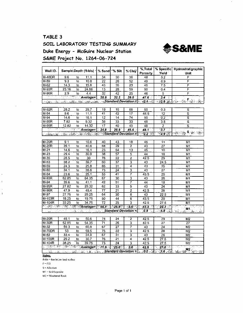
TABLE 3
SOIL LABORATORY TESTING SUMMARY
Duke Energy - McGuire Nuclear Station *S&MES&ME Project No. 1264-06-724
Well ID, Sample•Depth (ft-bls) % Sand •% Silt % Clay %~,Total % Specific HydrostratigraphicPorosity Yield' Unit
M-48DR 9.6 to 11.1 34 30 36 48 3.2 FM-59 9.3 to 10.8 22 26 52 49 0.9 FM-62 14.3 to 15.8 .43 35 23 45 7.5 FM-93R 23.16 to 24.66 13 28 59 50 0.4 FM-96R 2.9 to 4.4 32 42 25 46 5 F
7 i'Average- 28.8 I322 39.0 47.6 3.4 FS_______________._. Standa.d DeViation= 2. 2.9 . y~:
M-92R 28.2 to 29.7 19 15 66 50 0.3 SM-94 9.6 to 11.1 41 42 17 44.5 12 SM-94 14.6 to 16.1 12 14 74 50 0.2 SM-95R 7.82 to 9.32 35 33 33 48 3.8 SM-95R 12.82 to 14.32 17 40 43 48 2 S
____Average, 24.8 28.8' 46.6 48.1 '3.7______ j Standard Deviation~ 2.2 4.9__ _________
M-20R 9.1 to 10.6 40 43 18 45 11 M1M-20R 39.1 to 40.6 68 29 2 43 27 MlM-21 14.6 to 16.1 23 64 13 45 10 M1M-23 29.4 to 30.9 38 57 5 44 18 M1M-35 28.5 to 30 76 22 2 42.5 29 M1M-53 38.2 to 39.7 60 37 3 43 24.5 M1M-59 24.3 to 25.8 65 31 4 43 25 M1M-60 34.1 to 35.6 73 24 3 43 27 M1M-64 23.6 to 25.1 53 41 7 43.5 20 M1M-93R 62.85 to 64.35 67 30 3 43 26 M1M-94 39.6 to 41.1 42 51 7 44 18 M1M-95R 27.82 to 29.32 62 33 5 43 24 M1M-96R 47.9 to 49.4 77 21 2 42.5 28 M1M-97 27.75 to 29.25 64 30 6 43 22.5 M1M-103R 18.25 to 19.75 50 44 6 43.5 20 M1M-104R 33.25 to 34.75 72 25 3 42.5 27.5 M1
A V~ageO 58.1 '36.4~ ~5.6 43.3 22. MlS______________ Standard Deviation = 08 5.8.2.
M-20R 49.1 to 50.6 74 24 2 42.5 29 M2M-30R 52.85 to 54.35 71 26 3 42.5 27 27M-32 59.3 to 60.8 67 27 7 43 24 M2M-70DR 53 to 59.5 75 22 3 42.5 28 M2M-82 33.4 to 34.9 67 31 3 43 26 M2M-10OR 29.2 to 30.7 76 21 4 42.5 27.5 M2M-104R 38.25 to 39.75 73 24 3 42.5 27.5 M2
A veragp= 1 7 1 .9 ~2 5 ý0 3.6 = 4o2.6 27.0 ýM2
Notes:
ft-bIs - feet below land surface
F = Fill
S = Alluvium
M I = Soil/Saprolite
M2 = Weathered Rock
Page 1 of 1

TABLE 4
SECONDARY POROSITY SUMMARY
Duke Energy - McGuire Nuclear Station
S&ME Project No. 1264-06-724
*S&ME
F HYDROSTRATIGRAPIHIC: UNIT
Partially Weathered/Fractured Rock (WF)
Sound Rock (D)
Ngtes:
Secondary porosity ranges for WF from Legrand, Harry E. Sr., A Master Conceptual Model for Hydroqeoloqic SiteCharacterization in the Piedmont and Mountain Regions of North Carolina 2004.
Secondary porosity ranges for D from Daniel, C. C., III and Dahlen, P. R., 2002,Preliminary Hydrogeologic Assessment andStudy Plan for a Regional Groundwater Resource Investigation of the Blue Ridge and Piedmont Provinces of North CarolinaU. S. Geological Survey, Water-Resources Investigations Report 02-4105, 60p.
Page 1 of 1

TABLE 5GROUNDWATER LEVEL SUMMARY
Duke Energy - McGuire Nuclear Station
S&ME Project No. 1264-06-724
*S&ME
Ground r WaterSurface Well Depth to Level Water
wl E t p Dat Groundwater ColumnElevation Depth' Elevation\ ft(ft-msl) (ft-bls) (ft-bls) (ft-msl) (ft)
M-20 705.99 48 2/21/2008 38.00 667.99 10
M-20R "706.17 67.92 2/21/2608 ......6. 670.49 2.24
M-21 764.71 50 2/20/2008 34.42 730.29 15.58
M-22 786.71 60 2/2020081 4.8 736.85 10.114
M-22R 786.82 92 2/20/2008 50.54 736.28 41.46
M-23 ,7j5.52~ ;47 a2/21/2Q008~ 38.13+ 737~.39 8.87
M-30 733.46 50.7 2/20/2008 44.76 688.70 5.94
M-3,0R, '733.8 0 78.5 ' :2/20/2008 45.00 '688'.80 ';.. 335.
M-31 771.07 40 2/20/2008 27.94 743.13 12.06
M-2 .~ 790.13 55' 2/21/2008 5~2.29 737.84 2.71
M-33 771.78 38 2/20/2008 32.73 739.05 5.27
M,734R' 800.74' 61.9' 2/20/20098 ' 45.32 ' 755.42 ,16.58a
M-34DR 800.94 89.9 2/20/2008 45.42 755.52 44.48
M..35 '767.34~ 30. 2/~20/20b8 23.98 743.36 6.82
M-48 760.39 19.8 2/18/2008 19.67 740.72 0.13
'M-48R 760.33' 34. 2/18/2008 21.26 739.07 13:14
M-48DR 760.51 89 2/18/2008 44.44 716.07 44.56M-53~ 4.' 760.57a2 "23, a 2/18/2008 56 4.5 73
M-55 760.09 20 2/18/2008 11.30 748.79 8.7
M-5 2/18/2008 ,26,15 733.8870 9066
M-60 779.50 39 2/21/2008 29.35 750.15 9.65
M1-62 760.37: 36 2i'o,8/2008 .27.23 733.14. 8.77ý
M-64 760.84 28 2/18/2008 17.12 743.72 10.88
760.43' 27, ~2/118/2008 a 17-96 742.47 9.04A
M-66R 760.47 75.8 2/18/2008 22.59 737.88 53.21
M-70 760.44 '.215 2/18/2008 13.40 747.04 7-6
M-70R 760.44 65.45 2/18/2008 14.97 745.47 50.48
M-70DR 602"77.4. 2/18/200,8 15.12 .745.30 '62-28
Notes:
Ground elevations surveyed by Duke Energy
ft-bls Feet below land surface
ft-msl = Feet relative to mean sea level
Page 1 of 2

TABLE 5
GROUNDWATER LEVEL SUMMARYDuke Energy - McGuire Nuclear StationS&ME Project No. 1264-06-724
*S&ME
NM-82 675.23 34.6 2/20/2008 26.30 648.93 8.3
M-84R 657.75 25 2/191/2008 9.34 648.41 15.66
M-91 745.72 39 2/19/2008 27.53 718.19 11.47
M-92 728.41 34.5 2/19/2008 4.76 723.65 29.74
M-93 756.60 43 2/19/2008 33.78 722.82 9.22
M-94 751.40 441 2/19/2008 32.61 718.79 11.49
M-95R 731.65 44 2121/2008 21.30 710.35 22.7
M-96R 747.40 87 2/20/2008 24.46 722.94 62.54
M-98 721.61 27 2/20/2008 13.69 707.92 13.31
M-100R 732.09 47 2/20/2008 29.31 702.78 17.69
M-103R 696.00 36 2/19/2008 13.18 682.82 22.82
M-104DR 714.04 76 2/1912008 1 40.92 673.12 35.08
Notes:
Ground elevations surveyed by Duke Energy
ft-bls Feet below land surface
ft-msl = Feet relative to mean sea level
Minimum = 4.76 648.371 4
Maximum = 52.29 755.52
7I-
Page 2 of 2
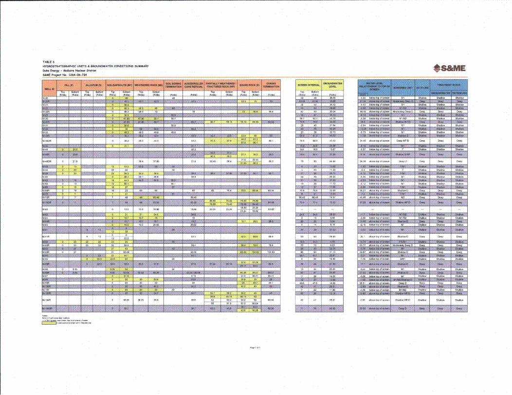
TABLE 6hf'MWtSTAATVRMP84C 9jTS A GROUMIWATh6 CONOITU)NS 9SUMMARY0668. EmsWg - MW6..' Mmd. 53.31oSA4%E PfojWs No. 1264-06-724
*S&ME
433 38.2
. ! 101 21A 17 ý l. 2• 6.A'6! ~.2 _______
343 I98 81I8I8I L.1 : I 598 28e8
JM-eo - IO -3. I 18.6 18.8B 2ý 1 21 N
wFA91R 6 13 1 "1 1 t25 2.1 -F I)J -.241 I -
0885
0 3825 I 38.40 39.8w1w 1118
324 45.14 45.18 5252 521 52.4 38 69.08 296~~ ~ 19320 -188 508280 I9808 I S.o ýI080
II ~I Iii I I 44.8 99.28mm ý 1 - 1 - 0-
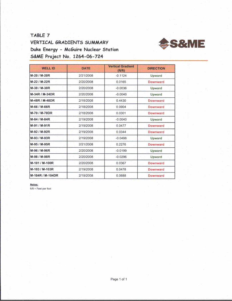
TABLE 7
VERTICAL GRADIENTS SUMMARY
Duke Energy - McGuire Nuclear Station
S&ME Project No. 1264-06-724
*S&ME
M-20 / M-20R 2/21/2008 -0.1124 Upward
M-22 / M-22R 2/20/2008 0.0165 Downward
M-30 / M-30R 2/2012008 -0.0036 Upward
M-34R I M-34DR 2/20/2008 -0.0040 Upward
M-48R / M-48DR 2/18/2008 0.4430 Downward
M-66 / M-66R 2/18/2008 0.0904 Downward
M-701 M-70DR 2/18/2008 0.0301 Downward
M-84 / M-84R 2/19/2008 -0.0040 Upward
M-91 / M-91R 2/19/2008 0.0477 Downward
M-92 / M-92R 2/19/2008 0.0344 Downward
M-93 / M-93R 2/19/2008 -0.0498 Upward
M-95 / M-95R 2/21/2008 0.2276 Downward
M-96 / M-96R 2/20/2008 -0.0199 Upward
M-98 / M-98R 2/20/2008 -0.0296 Upward
M-101 / M-10OR 2/20/2008 0.0367 Downward
M-103 / M-103R 2/19/2008 0.0478 Downward
M-104R I M-104DR 2/19/2008 0.0688 Downward
Notes:ft/ft = Feet per foot
Page 1 of 1

TABLE 8
PERMEABILITY TESTING SUMMARYbuke Energy - McGuire Nuclear StationS6ME Project No. 1264-06-724
*s&Me
M-22R 786.82 87 to 92 699.82 to 684.82 171.0 t 75.6
1 71.6 to 80.6
4.40E-05
2.38E-05
87 tO 92 2.00E 04
1
fi3 3.6 35.7 tO50.7 697.76 Mo 682.76 13517 W 50.7 4.65E-04
Ai 7707 20 to 40 746.07 t, 731 07 35 to 38 5 99E Cý 25 to 40 1 12E033
77 8 23 !o 38 748.78 t. 733 78 23 to 38 1,41E-04
9WR 80 79.9 to 89.8 721 .4 to 711 .. 04 b 0 79 9 to 89. 6 14E-05 b.14E-05
8.B 6 3 8 to 19.8 750.9o 740 59 8.8 t 19,8
44W 76o 81 79.51 o 6Ili5 81,3 to B6 3 4,HOE-05 79 to 89 1,1E-06
"s 70N 5 to 2C 7550 ,o 4.0 6 5 to 20
79450 to 38 5.0to705 31 to 34 8.73E*05 24 t. 396164
0413 to21. ,4 o728 13 to 28 2.4E0
04ý 7 1 t T7 1443w 33483 12 11. v 07E*05
NT 604 0.8 Wo 7&.8 6W9.67 Wo 684C67 69.54 Wo 74.54 1.02E-04 70.8 to 75.8 1.70E-06
M6•4 to 7954 1 A19E 05
55R76 SAS Wo 65.45 7.4.99 mo am49N 49.2 to5.1 1.03E-06 55.45 to 65.45 1.88E-O4
5O to 15 .38AK0
15 65.0 4 to 14 655,50 to 64 5050 4 Wo 14 3169E-04
Page Iof 2

TABLE 8PERMEABnILIY TESTING SUMMARY
Duke EnWrgy - Mcwuire Nuclear Statn
S&ME Project No. 1264-06-724
*S&ME
M-91R 7 S3 1. , 1ý .o 1, 1I l I 253 0 63 0175E-05 52 to 59,. 16 "1 C5
45,66 Wo 48.7 407CIE
M-2 2.1 70 to 75 6958.31 to 653.31 5 8.4 to 64.9 283-47 o 7 .52E-0
..- 7 747.76 1. to 5 7. M 1.1 I . 1 1 1 1 ,22 Ioto3.0E-5 t to 26 t--2.71-51.9 to 4.4 1.65-0
I •9 271 4. o 47.6 68011 o 675.1 iI.... I Ii7:01 2jt 2 42.6 to 4765 11E)
I-9 I 4 1 5 ] 3. . . I .. 3-. I .5 ., 6 .5 . 7,906.04 42 to ,, 2.571 2.111 141,DRI- -71 7FJ -W ?a 1 543 04 1. Q&04kJ-W- 4ý04T 1 7-7 1 1 j iii-04 I I I f
KNae-.(ft-b1s) Feet baoo lard Sur'fae Not enough watert 1 mwed to pertool rist 0 head slog esto(11-1d) = Feet reltive to e0s9 tamWl Recharge too fast to pumnp safter, W-10 dow for smg head sg tooest- Bodg abandoned due to absene of wte, Stog toot perfoboed, but data is not ret0ivble0 f0 data logg9r
1. A6l t cOtdoctvfty values am 0 e01 00l ete0s pe0 seco00 (.tso)
2. Test Interls with multi conductivity talues, wer0 conducted t cross m9l99 p9 hydrostratigtaphic to; conducthlty assigned to each signit6ca0n t hytosotatlospbOc unt for cor6putations.3 Tabled data Is h5r09 Glotand,.te0 Protactm Monitoringw 90; Ultimate d06t co00,t and 09me1*hydmu9conductivities4sho0019were0c90 mputod0us additional0data00 from UFSAR.
MIEAN(G65951 W0 2.296E-041 2.74E-04 I 60E-04 I 140E-05 7.796-,05 6.0412-051001(- 000.8 . ."OO 2 2 43 7 1 7 450640 0010tF94016.0 2,26E-04 I2.746-04 I1.54E-04 I3.41E-OS 6.906-05 4.586.15j
Page 2 of 2

CHART 8A - Mean Hydraulic Conductivity
(GWP Wells, UFSAR Wells, Landfill #2 Wells)
3.OOE-04 -
2.50E-04
4 2.OOE-04E2._
1.50E-04
0
. 1.OOE-04
5.OOE-05 -
O.OOE+001
Hydrostratigraphic Unit
0 Fill EAlluvium 0 Soil/Saprolite M Weathered Rock U Partially Weathered/Fractured Rock U Sound Rock I

TABLE 9
GROUNDWATER VELOCITY ESTIMATES SUMMARY
Duke Energy - McGuire Nuclear Station
S&ME Project No. 1264-06-724
*S&ME
Mean Groundwater Velocity
I feet per year 20
feet per year 4feet per year 43feet per year 47
Notes:
cm/sec = Centimeters per secondft/ft = Feet per footUnit Converstion cm/sec to feet/year = * 1034775
Page 1 of 1

TABLE 10
TRITIUM IN GROUNOWATER SUMMARY - (ME88UARY 2008 SAMRLN EVENT)
N" Eorg - M*c&w MwI.8" Statl.$&8ME P-Jct No. 1264-06-724
*S&ME
1-20 ml •t29G 5770
11-20R 2/27/20m08 4950
M1-21 68
M-22 2=207200 <80t
M-22R 2/20W2000 442O
M1-23 272772008 <308
M-30 272072000 '-II
M-0R 2720/2008 2080
M4-31 2/20/2008 <-700
M-32 2/272008 <-440
M1-33 U8.'.M19. . - 0.80. P'onmNu
M-M 21020 ý.37 7
M-34DR 272072008 -3 1
M-35 272012008 '-00
M-42 27le82008 9700
M.,48 Ur.<v8.0 Sonpw. Wo T 8 .
M11-R 27 872088 7080
M-480R 277872000 7530
MI-3 2187'200 70800
M-55 211812008 '003
M,-59 271072000 "450
M-80 212*/2000 <086
M41 2 2780 ' 00
M1-64 277872008 7000o
M48 2/18720 5 0
M-860 271872008 %305
M4-8 2782008 70200
M-70 211782088 3450
M-70R 2/ 20 2730
M-70DR 2778/2008 <025
M-72 211782008 7990
M-76 2/1/2 9860
M-82 2/20Iw00 78o80
4-84 2/1192006 s55o0
M1-4R 2717872008 0300
M.-86 27972008 7130 0
M-87 2119/200" 2080
M-01 271972008 U210
M-891R 2/12008 2080
M1-2 2119r2008 2190
M.-92R 271972008 '208
M-93 277972008 2090
M-03R 2707r2000 2700
M-94 277972000 <4 1
M-95 27/272008 3800
M.-9R 2121t2008 <142
M-06 -Noroo 0•4
M1-0R 2r202oo0 <00 7
M1-7 27M2008 1550
M-48 Z20,"rM <-10 l
M-88 272072000 -70 2
M-100R 272072008 030
M-101 27207200 3080
4-102 211/8008 77400
11-103 278/2000 250 0
[.103R 277972008 17400
M-104R 271972008 107000
.1-8400 2/19r20 60300
1S-1 2720/2008 '775
118-2 2/1920 98 0
115-.3 277872008 8000
1S-4 2197/2008 600 0
P081 o 1

TABLE 11SAMPLE COLLECTION MEASUREMENTS SUMMARY - (FEBRUARY 2008 SAMPLING EVENT)
buke Energy - McGuire Nuclear StationS&ME Project No. 1264-06-724
*S&ME
943 20266 44 5.6 73.5 NIA NA 1. .2 0 NO 17 7/ N3 WA5A W
M-3405 WA INA 75 5 NO 16.8 21. 9
94.62S4 21600 614 2.5 3.69 WAI NA 42f 7 5.9 120% No 24. 35.,73,4. a61 76
945 (662 31 53 4.5 WA NA 1.F 9 1.26 1.5 NO 214J 32.0 5.06 171 707 6.3
- 59 29N66
A NA 17
NO 20
5104. 4
31 159
14-62JT NI606 361 706 731A INA 1.7 14 14 0.5 NO 17.6 769.0 5.36 20 415 7.3
946 1/20 271 17.62 742.47 WIA NA 1. 5 .5 1 NO 167. 42. 4.9 359 3 9 9816
M46 3 (6064 3.3 25.06 734.7 W2NA NA 17 130 72.99 12 NO 20.9 5231 5.720 23.5 416 7.6
3,&"0 2(600 426 1.5 745.4 WA NA 1.7 140 .0 1 NO 17.7 t7,o 6.9 275 23W 15.3
9 4-7 218/20 22.2 6.75 751.06 NIA NA 380 A 0.2 0. 325 YNS 20.6 36.7 4.4 6. 479 2.023M 7
sm AIS IW N LF no T &5 NO 2A 1*0 6" 1 272 2.3
KAý5 1 3 12 15 7 74 9 NLI NA F 1C 12 1 NO 1 432 05 J 171 707 62A131F
M-W "N M64 4&7 WA A L, 30 1 x 212 im 4- 3435AV2.1
f611
m 59 1; 280 73 88 NuA NA 171 075 N 230 756 6H 2 36 44
L 5.3ý: 10016 WA- NA tvs 160 1% 5 NO i9A 69.0 8 m 2 0
27 0 73 14 ,A A LF - 4 0 7 NO 17 8 69 2074427 3
zm lrý -3.72NA I9, W NO 4) &o lo 4427.8
1 17 62 742 47 IA NA L 55 1 N 17g6 2035 3% 81
=4 73798 WA NA Lf lt NO ITA "38.7ýU 4
Not":ft.691 Feebl- 64100.4 N4,4e
4,416-. = 1.666 p.e 4,04
on4,/W- =~~ M oboh pe. -W.R.,~e
NTU = Nepf640rP/4c Wrb940y eek0-v =Mwoo
nrg/1 = 66648/4,,wp.464,
NA W W6 oeyedNIA =Not w6940491
1.7 L-.0 flowCF Cwvoef~one pw"6(39w15 weR vokere)
BP =N. V.eW (H-yd.eSeeo)
P76e l12

TABLE 11
SAMPLE COLLECTION MEASUREMENTS SUMMARY - (FEBRUARY 2008 SAMPLING EVENT)
buke Energy - McGuire uicdear StationS&ME Project No. 1264-06-724
06&InME
¶485 2/9304 714 9.8 833 A N F 350 1127 1.75 NO 13.3 51. 591 115 452 4.64
¶44 1900 71 .0 1) A NA LF 220 1.97 1.5 NO 14.4 27.2 4.9 6.5 464 1.17
¶91 21508 661 31.77 71.0 !A NA It 105 5.66 5.5 NO 14.81 103.2 73.35 20.4 ¶40 8.1
1492 2/900 78.82 9.29 72.0 IA NA LF 115 ll 11.4 1 NO 13.58 257.8 5.13 85 283 7.40
w493R 2/920 84 414 N2A A NA 1.7 2503 10.48 3.5 No 13.0 158.5 7.01 58 300 ¶1150
¶49w /2/08 40 16.18 1.5 W NA LF 120 1.28 0.75 NO 18.23 215.1 6.21 32.8 162 5.05
¶49 20206 374 28.42 72.8 ,A NA LF 1770 1.47 1 75 NO 17.15 58.2 5.88 201 4,23 3.5
¶4-97 2 20698 28.2 13.7 772 2 WA NA LF 250 2.0 0.75 NO 19.83 5905 8.73 '1000 382 5.43
,A--.R :/20120.- 55.80 17.1 70.8 WA NA It 200 5.48 7.21 5 NO 15.77 153.8 9.27 8 -28 0.33
¶411 22020 45N19/732 A NA It 285 2.0 25 NO 18.85 351.0 7.65 77.8 158 2.55
1410 ,/19255 25.30 15.16 884 NA NA LF 330 1.08 1.75 NO0 14.38 137.0 5.90 w8 458 8.9
¶10R 21/04 53.92 42.43 875.15 WA NA L.F 185 1.87 1.25 NO0 15.71 231.8 8.55 1.5 373 5.33
¶4-N22/20 A W;A NA NA NA 1.7 NA NA 1.25 NO 11.32 51. 512 10.7 182 5.87
¶4-3 2/8/00 W NA A A A LF NA NA 1.25 NO ¶4.41 39. 872 6.45 34 10.21
Ciý vlw~zow 4ý4Lp NA No 6AD u4.2u6 G1 2 .
NA 410 01007004fL/n,9 = L888b.1- i.1
4 -ff
pm~ho/10 - Mao08080 ohm npr m el-trNTU = NWs1lOo,45¶o h6144y 0088
toy= M6wvoft15/L. =88514010 P01 841
N/A Not 485I/Ott¶
LF L- fl0owCP CO000ionN4 purge (31to501080084000s)BP No 7.015 (HydraSle-o)
Page 2 of 2

I
R NV II0 " ME S ~ U N U~ l TATIONS STATION LOCATION A PROPERTYMA
sumE NEROY - meUmOEN~ STATION II I*6&ME
QWSIN O Jf

2 ~/7~3 ~.~- IS',
K
-K'
If II-
I .
MCOUIRE NUCLEAR STATIONUNITED STATES GEOLOGICAL SURVEY MAP *S&ME
ýw NMEINC CONDUKE ENERGY . MCGUIRE NUCLEAR STATIONMECKLENBURG COUNTY, NORTH CAROLINA

'-
iII-
.i
~4ŽIi
'I
N'
It(
i1II * N.
\
/
~
A
'N ~ N
II'N
IIN
N N
I IN'

II4
i* j-.'!. 1'
p.
7
'!~
•o
I
L
.~*
II(
1I K
a
r~ <~
/ I>
''I<K
a
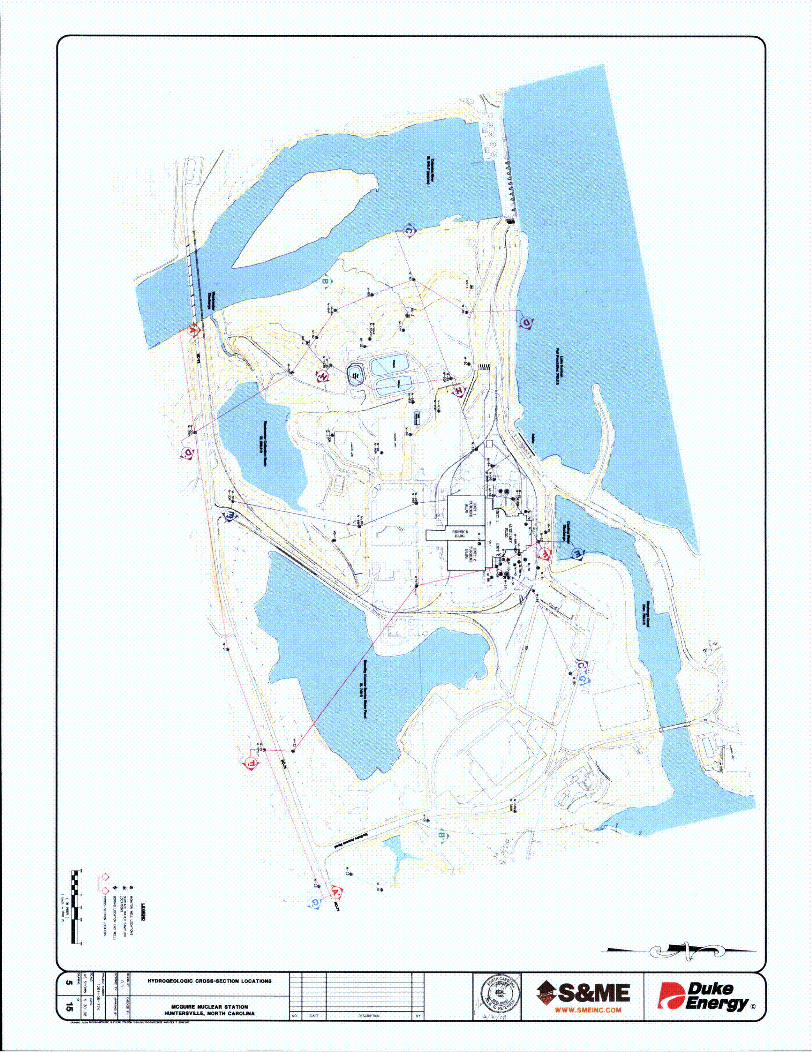
A'
/
I/
f'AU
7 -ii
III.I /
~ U
\II/
)'4
N N>1
1<>4
\ A j-s
iiy
)

i g g a a8 a; as a a -1 a. a 1 a as a .a
Kq
HIP
TyI
S a a a a a a a a a a a aa9~999 lI~1I ~
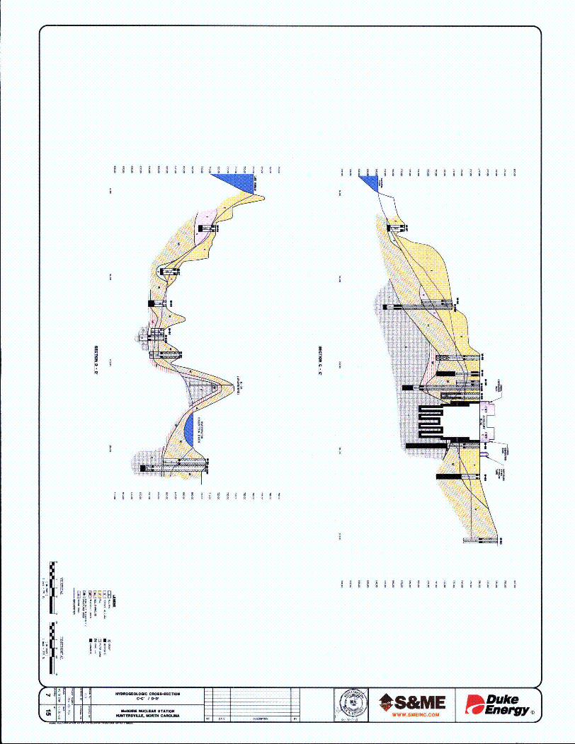
B B B B I II II B~B BB B B BBB I8 8 88 8 88 8 B 8 B 8 8
i
!I.
1 1 1 1 1 1 1 1 B 1 B 1 1 B B 1 ! B .
I8~~8~]ii I:. I
I B B B B I B I B B B B B B B B B B I
Nounu

PB N R A .
!
I
I ~ I I I I I I I ~ 8 88 1 II 81 88 I 888 I
B B B B B B B B B B 8888 B B B B
EB~UU~! ~

1. -IR A A A A
I I I I A A Aa a a a a a a a a a
N q
III~
I R R ~ I I A A A A A A A A A A I I
* !A Ua

Iif
-x
k
-I
/ _ 1iix -
II
//
S V * \ :r~
NVN
N- ~ -!
- 'II
LN~~ \ ~,. /
IIj;jii~ i
-
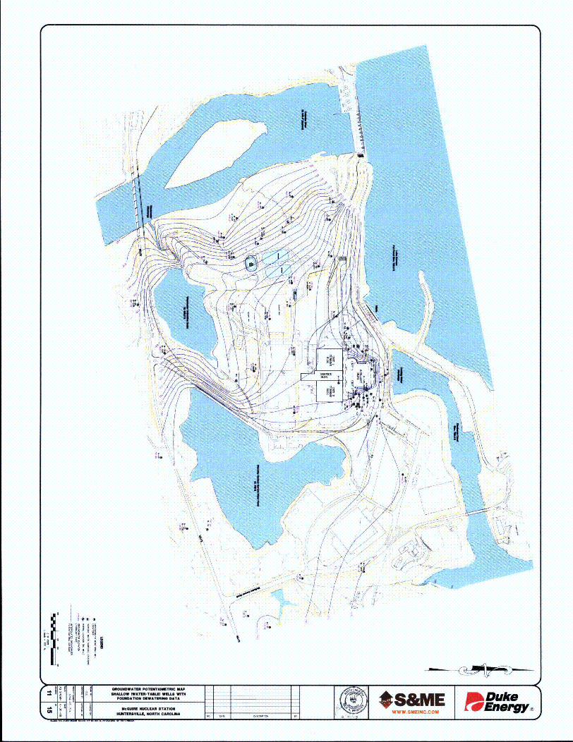
I ifx\
A
III 2
1
<if
'F
ii \ \
IbN /
//
/
A N
*1
~1 2•
/q u Ii
II

~NI ~- - -
'U UII~f
( K
Ii I,.N I
1 ~'*
* * '- fld~~ ~
9 "U
Nj~\ V'III 9*,--
'.'~ -' 1 ~ ~ *~~n ii1 ~
~ -~~- :~N /
- A 4</
*~'v*> ~ /19 1' **~ I \, <-I
at /I /I
//
* -'
* I
- ~,-
N
i~ ii ~ ~ I~ ;~ I

7, II
/
it 'I
-if ~*N
<it K,
'Vit
it L
K, >I~A,;~
IiI
I
-N
4 ~<:~ I,
I "
j~1.
-N ~ I- -~ I
N
,
',, \~ \~
-\
/ / ~t,
~-\~ A~1k
I I
KA>
j /
V -
/
S I
N~ --
'7
I,
K. ~. 15
~ i~ ii II i~ ~
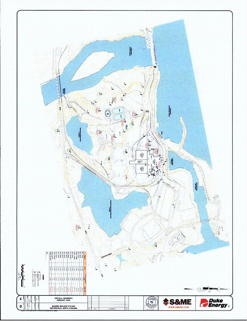
2
>1 II -i
I7-
LI
i.
N L~ ~\\ ~ p
v-N
I ~ -~ ~ V~7~ii 71\
I i¶- ~
~ ¶
&~ I V f
'N
N N. ~ N// 'RI ~'*
-N--
-* 3 \*,- N. /
/ 1A - /K~-
I /I
//t N N -i
~1' * i-"- *
N- 7 '~-
N.y.-. .- T- '*--,
VV ~1~ N
i.*

j ; A ~ ~ ~
I
'FI ~>
.9-
Al
(i -1•
i; N>'I
U ~ ~
~
~ II) V
N
'>~IIV
½ It
K.
(
<
~\
I ~'I ~ -~ ~ I
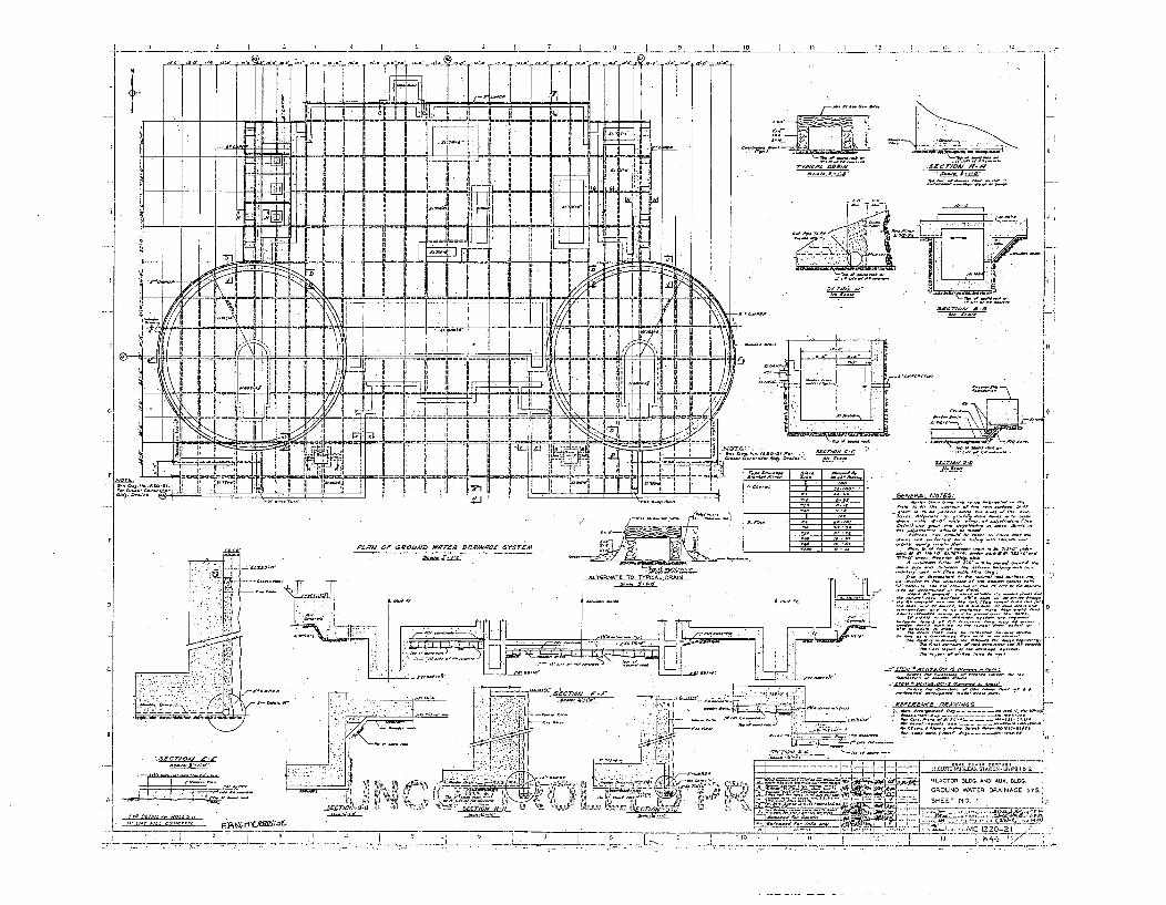
7 0 i 0 t II C
L +T- -7
17IF II
F-I 9 IF.LLjuu:
LA P- '
CO.SAC7YGA~ if-a- A
K
P-->F ----R•ll--T -- -- •
~i. ~LIIE1Ij'LHr1~-nh1Eum~FI•I It • I i i ]f
II
2\~ 1W
________ t~.I
I FIII I/•
-! - I I I
~- 44Iif
N =
7131[7 1 4! -J•l•L
-----
.... • • •• • • • • • • • •l• •!---- I
1K
/Mi-i
LUJ LM io
A II I
YF 1,
H
C-
FCA 000 A lipCCEO, *: - - -~
Nip. AA~,. I' It
=_•.
-,E I L.

____: _ .. .
[I
-4
9
~N fl~~IlOO
22~9~ 22~ 2~~S2~11 ~ A cd. ~r.22r
2222 ~%
A222,
2I
2 ~ 2 2i2,~.
2 2. 22 22 ~ 22 2

Figure 2-4.Plot Plan and Site Area

LAKE NORM,•
/
1--/
L.
Oct... ....L~ a .
q, *

Appendix BSource and Source Pathway Risk Assessment
B. I Determining Groundwater Risk Profile
In order to focus on potential contaminated sources and source pathways to groundwater,a risk assessment was performed on the plant structures, systems and components (SSC).This risk assessment took into consideration four distinct aspects of these SSC and theenvironment in which they are located. The four distinct aspects are the hydro-geologicprofile, the volume profile, the tritium profile and the engineering profile.
The risk assessment algorithm consisted of multiplying the four independentlydetermined profile values to establish an overall groundwater risk profile. The latter twoprofiles, the tritium profile and the engineering profile, were given more weight in thisrisk assessment than the former two. The final groundwater risk profile resulted in a rankordering of plant SSC with those higher on the list considered to be more "risky" and thusof higher importance to the Groundwater Monitoring Protection Project. Section 5.2.2contains a summary of the plant S SC of higher importance for the purposes of thisinvestigation.
Groundwater Risk ProfileProfile Profile Value Weight Formula
Hydro-geologic (HG) Section B. 1.1 1Volume (V) Section B. 1.2 1 Groundwater Risk (GW) Profile =
Tritium (H3) Section B. 1.3 2 Sum(Profile*Weight)/Sum(Weight)Engineering (E) Section B. 1.4 2
Sum 6
B. 1.1 Hydro-Geology Profile:
Judgments on the hydro-geologic profile were done by the Duke hydro-geologic subjectmatter expert. Hydro-geology profile risk ranking ranged from 1 to 5, with a highervalue indicating that the structure, system, or component (SSC) has a higher risk ofreaching groundwater if the contents escaped and/or discharging offsite.
Profile Definition5- Located in or at groundwater4- Located above groundwater but below land surface3- Located at land surface on exposed soil2- Located at land surface on improved surface1- Facility buildings / roofs / gaseous systems (leaks self-evident)
1
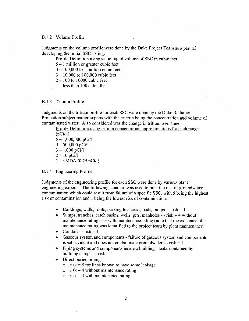
B.1.2 Volume Profile
Judgments on the volume profile were done by the Duke Project Team as a part ofdeveloping the initial SSC listing.
Profile Definition using static liquid volume of SSC in cubic feet5 - 1 million or greater cubic feet4 - 100,000 to 1 million cubic feet3 - 10,000 to 100,000 cubic feet2 - 100 to 10000 cubic feetI - less than 100 cubic feet
B.1.3 Tritium Profile
Judgments on the tritium profile for each SSC were done by the Duke RadiationProtection subject matter experts with the criteria being the concentration and volume ofcontaminated water. Also considered was the change in tritium over time.
Profile Definition using tritium concentration approximations for each range(PCi/F )5 - 1,000,000 pCi/14 - 500,000 pCi/l3 - 1,000 pCi/I2 - 10 pCi/lI - <MDA (0.25 pCi/1)
B.1.4 Engineering Profile
Judgments of the engineering profile for each SSC were done by various plantengineering experts. The following standard was used to rank the risk of groundwatercontamination which could result from failure of a specific SSC, with 5 being the highestrisk of contamination and 1 being the lowest risk of contamination.
* Buildings, walls, roofs, parking lots areas, pads, ramps - - risk = 1* Sumps, trenches, catch basins, wells, pits, manholes - - risk = 4 without
maintenance rating, = 3 with maintenance rating (note that the existence of amaintenance rating was identified to the project team by plant maintenance)
* Conduit - - risk = 1* Gaseous system and components - failure of gaseous system and components
is self-evident and does not contaminate groundwater - - risk = I* Piping systems and components inside a building - leaks contained by
building sumps - - risk = I* Direct buried piping
o risk = 5 for lines known to have some leakageo risk = 4 without maintenance ratingo risk = 3 with maintenance rating
2

o risk = 2 for drinking water lines and newly replaced polyethylene lines(Catawba)
" Ponds are end pointso risk = 5 for active pondso risk = 4 for inactive ponds
* Tankso risk = I for tanks in buildings where overflow/failure captured by building
sumpo risk = 1 for tanks outside with catch basins where overflow/failure
captured by basino risk = 3 for tanks outside without catch basins, but with a maintenance
rating on spreadsheeto risk = 4 for tanks / cooling towers outside without catch basins and no
maintenance rating on spreadsheet
B.1.5 Results
A full listing of the McGuire SSC Groundwater Risk Profiles is provided in Table B-1.
3
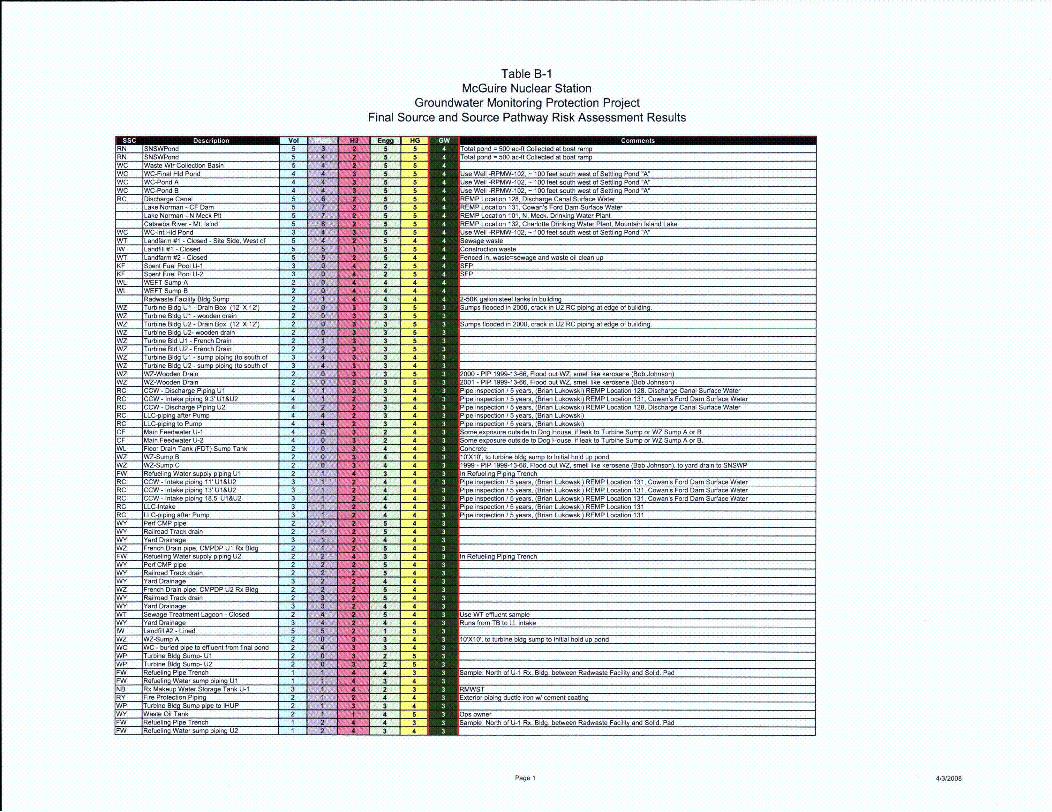
Table B-1McGuire Nuclear Station
Groundwater Monitoring Protection ProjectFinal Source and Source Pathway Risk Assessment Results
HIG5 5 total nd = 500 ac-ft Collected at boat ramp5 5 otlnd = 500 ac-ft Collected at roat ramp5 55 5 UJe Well -RPMW-1 02, - 100 feet south west of Settling Pond "A"5 5 Use Well -RPMW-102, - 10O feet south west of Settling Pond "A"5 5 Use Well -RPMW-1 02, - 100 feet south west of Settling Pond "A"5 5 i RMP Location 128, Discharge Canal Surface Water5 5 EMP Location 131, Cowan's Ford Dam Surface Water5 5 REMP Location 101, N. Meck. Drinkin Water Plant5 5 I EMP Location 132, Charlotte Drinkino Water Plant, Mountain Island Lake5 5 _se Well -RPMW-102, - 100 feet south west of Settling Pond "A"5 4 Sewage waste5 5 I onstruction waste5 4 Fenced in, waste=sewage and waste oil clean up2 5 SFP2 5 I SFP4 44 44 4 2 2-50K gallon steel tanks in building3 5 Sum s flooded in 2000, crack in U2 RC piping at edge of building.
3 53 5 So•wms flooded in 2000, crack in U2 RC piin at ed e of buildin3 53 53 53 43 43 5 000 - PIP 1999-13-66, Flood out WZ, swell like kerosene (Bob Johnson)3 5 001 - PIP 1999-13-66, Flood out WZ, smell like kerosene (Bob Johnson)3 4 FPi inspecton i ears, Brian Lukowski- REMP Location 128. Discharge Car3 4 FPip inspection / 5 years, (Brian Lukowski) REMP Location 131, Cowan's Ford3 4 Pi ins ection b5 years, (Brian Lukowski) REMP Location 128, Discharge Car3 4 li a ins ection / 5 years, (Bnan Lukowski)3 4 i inspecton / 5 ears, Brian Lukowski2 4 Sore exoscre outside too House, if leak to Turbine um or WZ Sump A2 4 Some exposure outside to Dog House, if leak to Turbine Sump or WZ Sump A4 4 IConcrete4 4 101X) 0', to turbine bld sump to Initial hold up pondI 4 4 I 1999 _ PIP 1 999-! ý3-66, Flood out WZ, -11l like kerosene (Bob Johnson), to y=
I 3 4 / In Refuelingp Piig Trnch.
3 4
2 5
4 4 Same~ insrectiof U --i Ru Id- betw en Lodw ateaioind11 Solid 's Pa rd
3 4
II 4 4
[] 3 4 In Refueling Piping TrenchI 5 4
5 4S4 4 mS 5 4 mIm 5 4
4 4 I
5 4, Us4Tefuetsml
I 3 4 I 10'XI 0', to turbine bldg sump to ntribal hold up pondS 3 4S2 5
[] 4 3 I arnpe: North of 111 R.Bd.btenRwatFcitya Sld. a
I 2 3 MS4 4 I Exterior piping ductie iron w/ cement coating
3 4[] 4 5 Dowe[] 4 3 Sample: North of U-1 Rx. Bldg. between Radwasto Facility and Solid. Pad
II 3 4 i=
Page 1 413/2008

Table B-1McGuire Nuclear Station
Groundwater Monitoring Protection ProjectFinal Source and Source Pathway Risk Assessment Results
Em HG2 3 RMWST3 4 Ins acted w/ additinal ins -i-nnsin 2-07 and 2008 planned (Ann Milton), sar4 4 UExWterior piping ductle iron w/cement coating4 4 NExter pipoir e iont l /ke.
5 41 1
3 4 WelI locations can assit in inspection of RN leakage from plant to low level intall 4 3 Cletda otnmm= 3 4 I=•nspected w/ additional inspections in 2007 and 2008 planned (Ann Milton), satmE 4 4 ELxterior moipir ducte ron (/eetcai~ Kent Davis)
3 4 Use Well -RPMW-102, - 100 feet south west of Settling Pond "A"3 4 Use Well -RPMW-102, - 100 feet south west of Settlig Pond "A"
5 14a hle: Noth oift U-aio nerolBd sabewee a dwse tr amet liandt oid a
4 44 4 Doc Parking & Yard to SNSWP
S 4 4 ?m?? Dicharge into ditch behind abandoned parking lot, south of lower lot - 2-3 p
4 4 4mm,4 4 ?m?? Dicharge at LL intake - 2-3 pipes
5 45 5
am 4 4 • Number discharge it ae5 5 H Between Training Simulator Building & lake
5 I
1 I Us Aux 1I Ec Sk1h
52 4 ircuates W water, sump could leak to Groundwater, normal flow to Floor[] 2 4 N Recirculates W1L water, sump could leak to Groundwater, normal flow to Floor Cul 2 4 n[] 2 2 FSam 3 4 . Well locations can assit in inspection of RN leakage from plant to low level intalam 3 4 • Use Well -RPMW-102, - 10DO feet south west of Settling Pond "A"
3 4
3 4 • Use WT effluent sample5 1 U,•se Aux Bldg Security Shack A/C sample5 1 •= Samole: North of" ---1 RxBdbtenRdwaste Facilityj and Solid Pad
me 5 2I S = Use Aux Bldg SecurityShack A/C sample
[] 2 2 m ~FWST3 4 lnsoacted w/ addi-onal' insec- os--- 0 and 2008 planned (Ann Milton), san
3 4 H Use VWT effluent sample
iN 4 m Use WT effluent sample[] 1 • se Aux Bldg Security Shack AJC sample
S 1 • Use Aux Bldg Security Shack ANC sample
S 1 S ample. North of -----Blgbtwe Ra dwaste Facility and Solid. Pad
•n 5 1 •= Use Aux Bldg Security Shack A/C sample5 3
ms 3 4 Ilnspected w/ additional inspections in 2007 and 2008 planned (Ann Milton), san-] 4 - 3 Ietda otrm
[] 3 4 Inespected w/ addifional inspections in 2007 and 2008 planned (Ann Milton). san
[] 3 4
[] 3 4mm 3 4 m
n 3 Dri toceknolk
3 4 m[] 3 4
m z 1 • PS -Owner, added -2002[] 2 s
[] 5 1 •' Use Aux Bldg Securit Shack A/C sample
[
Page 2 413/2008

I
I
Table B-1McGuire Nuclear Station
Groundwater Monitoring Protection ProjectFinal Source and Source Pathway Risk Assessment Results
EN HG5 12 1 -50K callon steel tanks n buildi
• 5 1 iS I5 1
2 1 PS - Owner, added -20032 55 15 1 Use Aux Bldg Secunty Shack NC sample5 1 se Aux Bldg Secun Shack NC sample5 1
5 1
4 3 eroved
5 1m 2 4 m4 3
2 42 42 4
5 2 mm
5 3 m m
5 1
2 4
4 3
5 I
2 4
$ 1 m
S2 4 mS4 3 m
P 34 3am2m 4 3 mm 2 4 m m
2 4S 2 4 - 'm 2 4 '
4 Iln U2 CA Pump Room. EI-716
m 1 *m 1 '
4 Iln U1 CA Pump Roolm, EI-71634 HT-LudyHot Showr Tank EL 760'
4
3 mD ry, if leak from C ole, lowest elevalion
I D m r. if leak from Core. lowet elevation22 m
mR - Inei Rdat Fclt
Pag 3m m/20

Duke Energy - McGuire Nuclear Station
Existing Well ID Renumbering Reference TableS&ME Project No. 1264-06-724
*S&ME
OriginalWell ID
T-1T-2T-3T-5T-6T-7
T-1 0T-1 3T-14W-1W-2W-4W-5
W-15W-22W-42W-43W-44
RPMW-1RPMW-2
Ren umberedWell ID*
M-58M-57M-56M-44M-45M-46M-51M-50M-72M-90M-89M-87
M-105M-75M-74M-42M-43M-68
M-101M-102
* - Wells were renumbered as part of the Ground Water Protection Initiative Project at McGuire Nuclear Station

V c: ý)Z'M->•
Dun POWER GOM:PNYNUCLEAR PRODUGTION DEPARTMIENT
P.O. BOX 33189, 422 SOUTH CHURCH STREET
cHA.RLorrE, N.C. 28242I
(704) 373-4011
December 22, 1988
Dr. Eric J. KlingelRegional Hydrogeologic SupervisorDepartment of Natural Resources and
Community DevelopmentMooresville Regional OfficeP.O. Box 950Mooresville, N.C. 28115
- rl C. 101,..4, : .,.EN '27il~i, F I" *1*" Q
SE~lfi UiJ
DEC 2 7 1988
CENTRAL RECORDSIMrISION USENO ATTACHMENT TO FILE
FILE NO. ýC '.- ) - II
SUBJECT: McGuire Nuclear StationMonitoring Well PermitNo. 59-0667-WM-0183 Well #W-44File: MC-216.14
Dear Dr. Klingel:
As required by the subject permit, attached is the completed GW-l torthe groundwater monitoring well #W-44 located at McGuire NuclearStation.
Also, as required by the permit, listed below are the results of thewater quality analysis performed on this well.
Date
10/31/8811/7/8811/14/88
Parameter
tritiumtritiumtritium
Results
<350 pCi/liter<35G pCi/liter<350 pCi/liter
Please note that tritium was the only parameter for which an analysiswas conducted.
If you have any questions please contact Tami Story (704) 373-7016 orMitch Griggs at (704) 373-7080.
Sincerely,
.T.Simil TefnialSystem Manager
Nuclear Environmental Compliance
TRS/77/rhm
Attachment
bc R.P. MichaelR.J. WaldropD.W. PhillipsM.L. Birch
W.T. HortonM.C. GriggsStaff (route)MC-2002.02-13

NORTH CAROUNA DEPARTMENT OF NAIURAL RESOURCES AND COMMUNITY DEVELOPMENTDIVISION OF ENVIRONMENTAL MANAGEMENT - GROUNDWATER SECTION
P.O. BOX 27087 - RALEIW4.N.C. 27611, PHONE (919) 733-5083
WELL CONSTRUCTION RECORD
FOR OFFICE USE ONLY
Quad. No. _ Serial No.
Lat. Long. PcrMinor BasinBasin CodeHeader Ent. GW-1 Ent..__.
DRILLING CONTRACTOR MUKE POWER Qo.
DRILLER REGISTRATION NUMBER '1I-.STATE WELL CONSTRUCTIONPERMIT NUMBER: _.9-066.7-WM-0183
1. WELL LOCATION: (Show sketch of the location below]
Nearest Town: AlUTE-RJIL... e /t/. County: - LMECKL R.C
Depth(Road, Community, or Subdivision and Lot No.) From To
2. OWNER Duyq. ?Q'.js$ C.O. McGuire Nuclear Station
ADDRESS 2O. SOX 33I E9 GEE-.F_. P
DRILLING LOG
Formation Description
[Street or Route No.)CHARL TTE __1..3. 9?4?.
City or Town State Zip Code
3. DATE DRILLED IO-2z7-8fB USE OF WELL. M -INrTORUG
4. TOTAL DEPTH 6.A!Z CUTTINGS COLLECTED E'Yes C" No
5. DOES WELL REPLACE EXISTING WELL? 0 Yes ErNo
6. STATIC WATER LEVEL: 2 S .- FT. 0 above TOP OF CASING,a below
TOP OF CASING IS - FT. ABOVE LAND SURFACE.
7. YIELD (gpm): ,, METHOD OF TEST
8. WATER ZONES (depth): t.j, /N
9. CHLORINATION: Type to/" Amount W 1A,
10. CASING:Wall Thickness
o,,.-_.'.OLJ Depth Diameter or Weight/Ft. Material
From - To -33*' Ft. 235 .154- PVc.
From - To - Ft.-Ft
From - To - Ft.
11. GROUT:Depth Material Method
From 0:) To__... L Ft.-i _Ot4$.€r.'1e. p96UE.>
From V To ZI5. Ft. - C 4-b-e-^, j Pau _ L.,_r)
12. SCREEN: *1ftv
It additional
M - rat C.
\NF..L _nv-4
space is needed use back of form.
LOCATION SKETCH
(Show direction and distance from at least two State Roads,or other map reference points)
449-r9.5a4
Depth Diameter Slot Size Material
From 333.R' To 43_q Ft,.1j2c in. o..o in. F'J.-
From To_____ Ft. In._ in.
From - To_ Ft. in. - in.
13. GRAVEL PACK:
Depth Size Material
From 31.9 ".To--4i4i Ft. t37 SrND
FromTo_ Ft.__.
14. REMARKS:
I DO HEREBY CERTIFY THAT THIS WELL WAS:CONSTRUCTED IN ACCORDANCE WITH 15 NCAC 2C, WELL CONSTRUCTIONSTANDARDS. AND THAT A COPY OF THIS RECORD.S BEEN P IDED TO THE WELL OWNER4
S4 _a&

Form 25630 (R3-871 FORM M-26C REVISION 2
Form 25630 (R3-871 I FORM M-26C I REVISION 2THIS ORING DRILLEDWITA A.-KE AD-"r 01
PAGE OF .707 DUKE POWER COMPANY
CONSTRUCTION DEPARTMENTPROJECT /•\CI)1," -
SOIL TEST BORING FIELD REPORT
-- I OF ?= -
4 4p + qZ. 5246 "A"•,+ (A).4 3S "y"tTo0p OF PIPC' EL. 7.59.90
STARTING TIME ca IA.JOBNO.- A 1GROUND SURFACE ELEV. 76.0, (knJOB NAMF_.OnITD ' LL HRS. DRILLING N.4I HRS. MOVING -:DATE 10 '- 2t •, WEATHER f-COO INSPECTOR S - 3ATI.L M BORING NO. W)
SAMPLING I -r~SCAL
1ST6" 2ND V 3D - 0
5,7"
6 1 7.10 7
Io5,7 -4
15.7"
20.7
I- 2q, 2' 3 3.5.330.7".. .
7 Sq-.Z• -2,53i5 z'.. .." -;
dl
LE UD SOIL CLASSIFICATION AND REMARKS- i- 4
C14,P/MMt-r" franAAM Vcr-i}1: K~l(?Iig >', ý-'rA-rAA
Re-rAitJEr" S-MPL-"-t
-I.
4,..
-~ 4 %nUA
OQz-~ 4
-=
cc
00
.- LA)ET Raeki IN ANDM.D To RIJl,SAMPL STIL. Nn "
V.J
V; uj
z C12
ru d
+
.11-
BORING TERMINATEDr~iIIi Q'
METHOD OF ADVANCING BORINGi DEPTH4.
BORING REFUSAI CdD t4,RWATER TOB DEPTH I'Pa~WATER 24 HR: DEPTH .a.l&WATER LOSSES 1,4.CASING SIZ I"ENGTH rdI1A,
POWER AUGER
"RT01n ij;L. "v/yUD. wrtI AT:'f,D;O rC CI
o.O TO 1H97
---- "0--"

Form 25630 (R3-87) FORM M-26C I REVISION 2
DUKE POWER COMPANY "PAGE .-? OF
CONSTRUCTION DEPARTMENTPROJECT MC&GU 19
SOIL TEST BORING FIELD REPORTSTARTING TIME /,
JOB NO. A') .. GROUND SURFACE o LEiIIIA7,/JOB NAMP ('URO• 0,-F , h ,• " HRS. DRILLING NIA HRS. MOVING -6J4
DATE )b -ZfU -'9q WEATHERfO':,'-C0 l- INSPECTOR -S. "AT'IJM BORING NO. IJL- *
SOIL CLASSIFICATION AND REMARKS
• tzl
-U,
a- a
00
02
I4TI M,~ uJ
I
i
I
4
- M
0,
Z. n
4
4
I
I
I
METHOD OF ADVANCING BORING DEPTH
POWER AUGER 0.0TO 94.9'1I ADim i er: W4#A'JD:-AA*- ---- To--
PDATMfl NORGIL. ----~UC TO-~A~

June 15, 2005
Duke EnergyP.O. Box 1006Charlotte, North Carolina 28201
ATTENTION: Mr. D. Edwin M. Sullivan, P.E.
Reference: NCDENR WELL CONSTRUCTION RECORDSFOR RPMW-101 AND RPMW-102McGuire Nuclear StationHuntersville, North CarolinaS&ME Project No. 1264-05-349
Dear Mr. Sullivan:
S&ME, Inc. (S&ME) has completed the drilling and installation of two groundwater monitoringwells at the McGuire Nuclear Station. We are pleased to distribute the attached and completed NorthCarolina Department of Environment and Natural Resources (NCDENR) Well Construction Records(GW-1 Rev. 09/2004) for reference and record.
S&ME appreciates this and every opportunity we have to be of service to Duke Energy. We trustthis information is responsive to your needs at this time. Should you have questions, requireadditional information, or desire our assistance further, please do not hesitate to give us a call.
Sincerely,
S&ME, Inc.
ottE Dacus, P.G. PEProject Geologist Seni ineer/Project Manage,\
cc: NCDENR, Division of Water Quality, Attn: Information Management 2Attachments: Well Construction Record for RPMW-]01
Well Construction Record for RJPMW-102
S:\ENVIRON\2005\PROJECTS\6405349\NCDENR Well Construction Records (GW-l).doc
S&ME, Inc. (8641 574-2360155 Trodd Street (864) 576-8730 foxSparlanburg, South Carolina 29301 1 (864) 232-8987 Greenville l ,ww.nieIn:.om

WELL CONSTRUCTION RECORD
North Carolina Department o1' Environment and Natural Resources - Division of Water Quality
WELL CONTIRACTOR (INI)IVIDUAL) NAME (print) Bill Cole CERTIIFICATION # 2244
WELL CONTRACTOR COMPANY NAME S&ME, Inc. PHONE # &A 574-2360
STATE WELL CONSTRUCTION PERMIT# ASSOCIATED WQ PERMIT#(irtappllicable) (if' applicabie)
1. WELL USE (Check Applicable Box): Residential 0 Municipal/Public 0 Industrial 11 Agricultural 13Monitoring 9 Recovery E] Heat Pump Water Injection 0 Other 0 If Other, List Use
2. WELL LOCATION;Nearest Town: Huntersville County. Mecklenburg
McGuire Nuclear Station(Street Name, Numbers, Community, Subdivision, Lot No., Zip Code)
3. OWNER: Duke Power CompanyAddress 12700 Hagers Ferry Road
(Street or Route No.)Huntersvllle NC 28078
City or Town State Zip Code(M_)- 373-3719
Area code- Phone number4. DATE DRILLED 5/23 & 5/24/055. TOTAL DEPTH; 42 feet6. DOES WELL REPLACE EXISTING WELL? YES 0 NO P67. STATIC WATER LEVEL Below Top of Casing: 31.64 FT.
(Use "+" if'Ahove Top orCasing)8. TOP OF CASING IS 2.84 FT, Above Land Surl•,ce*
*Top of casing terminated at/or below land surface requires avariance in accordance with 15A NCAC 2C ,0118.
9. YIELD (gpm): METHOD OF TEST10. WATER ZONES (depth):
I. DISINFECTION: Type_ Amount12. CASING: Wall Thickness
. Depth Diameter or Weight/Ft. MaterialFrom_ 2.64 als To 22 Ft. 2 In Sch 40 PVC
From_ To Ft.From To Ft.
13. GROUT: Deplh Material MethodFrom 0 To 18 Ft. Portland Cement TremleFrom _ To_ _ Ft.
14. SCREEN: Depth Diameler Slot Size MaterialFrom 22 To 42 Ft. 2 in. 0.01 in. PVCFrom _ To Ft. in. in.
15. SAND/GRAVEL PACK:Depth Size Material
From 20 To 42 Ft. #1 sandFrom To _ Ft.
16. REMARKS:rRPMWý-101
Topographic/Land settingMRidge EOSlope OValley DIFlat
(cheek appropriate box)Latitude/longitude of well location
N35/25/48.93 W80/5715.45(dlegrees/uninutes/setan(Is)
Latitude/longitude source:0GPSOTopographic map(checek box)
DEPTIIFrom To
0 18.518.5 24.824.8 25.025.0 33.533.5 42.042.0
DRILLING LOGFormation Description
silty clayclayey slitsandsandy siltsandrefusal to hollow stemaugers
LOCATION SKETCHShow direction and distance in miles from at leasttwo State Roads or County Roads, Include the roadnumbers and common road names.
I D)O( IIERI-13Y CERTIFY THAIAT TillS WELL. WAS CONSTRUCTIEI) IN ACCORDANCIE WITI I 15A NCAC 2C, WELLCONSTRIJCTION STANDARDS, AND TI AT A COPY OFTI IIS RECORI) HAS BEEN PROVIDED TO TI11E WELL OWNER
SIGNA'TI'I•' OF PERSON CONSI'tJC'I'IN(G TI IE WI'I.L DA'TE
Submit the original to the Division of Water Quality, Attn: Information Management, 1617 Mail Service Center-
Raleigh, NC 27699-1617, Phone No. (919) 733-7015, within 30 days.GW-I REV, 09/2004

WELL CONSTRUCTION RECORD
North Carolina Department of Environment and Natural Resources - Division of Water Quality
WELL CONTRACTFOR (INI)IVII)UAL) NAME (print) Bill Cole
WELL CONTRACTOR COMPANY NAME S&ME, Inc.
STATE WELL CONSTRUCTION PERMITY1(il'applicable)
CERTIFICATION #j 2244
PIIONE q &4) 574-2360
ASSOCIATED WQ IPERMIT#(if applicable)
I. WELL USE (Check Applicable Box): Residential 0 Municipal/Public 0 Industrial 0 Agricultural 0Monitoring E1 Recovery 0 Il-eat Pump Water Injection 0 Other 0 If Other, List Use
2. WELL LOCATION:Nearest Town: Huntersvllle County Mecklenburg
McGulre Nuclear Station(Street Nane, Numbers, Community, Subdivision, Lot No., Zip Code)
3. OWNER: Duke Power CompanyAddress 12700 Hagers Ferry Road
(Street or Route No.)Huntersvitle NC 28078
City or Town State Zip (ode(950)-373-3719
Area code- Phone number4. DATE DRILLED 5/24 & 5/25/055. TOTAL DEPTH: 58.5 feet6. DOES WELL REPLACE EXISTING WELL? YES 0] NO !7. STATIC WATER LEVEL Below Top of Casing: 41.32 FT.
(Use "+" if Above 'l'op ol'Casing)8. TOP OF CASING IS 2.32 FT. Above Land Surface*
*Top of easing terminaled at/or below hlnd surfloe requires avariance in accordance with 15A NCAC 2C .0118.
9. YIELD (gpm): METIHOD OF TEST10. WATER ZONES (depth):
Topographic/Land settingr-Ridge FSlopo '-Valley OFlat
(check appropriate box)Latitude/longitude of well location
N35/25151.16 W80/57115.13(degrees/minutes/seconds)
Latitude/longitude source:DGPS0lTopographic map(check box)
DEPTHFrom To
0 8.58.5 13.5
13.5 28.528.5 58.558.5
DRILLING LOGFormation Description
slitsilty sandsandy siltsilty sandrefusal to hollow stemaugers
I1. DISINFECTION: Type12. CASING:
Depth
AmountWall TIhickness
Diameter or WVight/Fl. Material
LOCATION SKETCHShow direction and distance in miles from at leasttwo State Roads or County Roads, Include the roadnumbers and common road names.
From 2.32 als To 33.5 Ft. 2 In Sch 40 PVC - -
From To _ Ft.From To Ft.
13. GROUT: D)epth Material MethodFrom 0 To 29.5 Ft. Portland Cement TremleFrom To Ft.
14. SCREEN: Depth Diameter Slot Size MaterialFrom 33.5 To 58.5 Ft. 2 in. 0.01 in. PVCFrom To Ft. in. in.
15. SAND/GRAVEL PACK:Depth Size Material
From 31.5 To 58.5 Ft. #i sandFrom To Ft.
16. REMARKS( 1tA:j1
I DO IIIZREBY CERTIFY TII lAT'P1 118 WELL WAS CONS'I'RUCTED I) IN ACCORDANCE WITII 15A NCAC 2C, WELL,CONSTRIUkCTI)ON STANDARDS, AN1) TH IAT A COPY OFTI I IS ItRECORD I IAS 1E3 UN PROVIDEHD T') I I1E WELL. OWNIE'R
SIONATUI'RI" OF PERSON CONS'I'TRJCTING TPJ IE WELL I)A'I IF
Submit the original to the Division of Water Quality, Attn: Information Management, 1617 Mail Service Center-Raleigh, NC27699-1617, Phone No. (919) 733-7015,withi 30 ditys.
GW-I REV. 09/2004
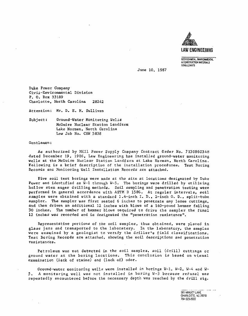
LAW ENGINEERING
GEOIECHNICAL. ENVIRONMENTAL& CONSTRUCTION MATERIALS
CONSULTANTSJune 10, 1987
Duke Power CompanyCivil-Environmental DivisionP. 0. Box 33189Charlotte, North Carolina 28242
Attention: Mr. D. E. M. Sullivan
Subject: Ground-Water Monitoring WellsMcGuire Nuclear Station LandfarmLake Norman, North CarolinaLaw Job No. CHW 5838
Gentlemen:
As authorized by Mill Power Supply Company Contract Order No. 7130860348dated December 19, 1986, Law Engineering has installed ground-water monitoringwells at the McGuire Nuclear Station Landfarm at Lake Norman, North Carolina.Following is a brief description of the installation procedures. Test BoringRecords ana Monitoring Well Installation Records are attached.
Five soil test borings were made at the site at locations designated by DukePower and identified as W-1 through W-5. The borings were. drilled by utilizinghollow stem auger drilling methods. Soil sampling and penetration testing wereperformed in general accordance with ASTM D 1586. At regular intervals, soilsamples were obtained with a standard 1.4-inch I. D., 2-inch 0. D., split-tubesampler. The sampler was first seated 6 inches to penetrate any loose cuttings,and then driven an additional 12 inches with blows of a 140-pound hammer falling30 inches. The number of hammer blows required to drive the sampler the final12 inches was recorded and is designated the "penetration resistance".
Representative portions of the soil samples, thus obtained, were placed inglass jars and transported to the laboratory. In the laboratory, the sampleswere examined by a geologist to verify the driller's field classifications.Test Boring Records are attached, showing the soil descriptions and penetrationresistances.
Petroleum was not detected in the soil samples, soil (drill) cuttings orground water at the boring locations. This conclusion is based on visualexamination (lack of stains) and (lack of) odor.
Ground-water monitoring wells were installed in borings W-l, W-2, W-4 and W-5. A monitoring well was not installed in boring W-3 because refusal wasrepeatedly encountered before the necessary depth was reached by the drill rig.
501 MINUET LANECHARLOTTE, NC 28210704-523-2022

Duke Power CompanyLaw Job No. CHW 5838June 10.1987 -2-
Reference elevations for the monitoring wells had not been determined prior tothe completion of this report. Enclosed is a map that shows the approximatelocations of the monitoring wells W-1, W-2. W-4 and W-5 as well as the locationof boring W-3.
ThanK you for the opportunity to provide our professional geotechnicalservices during this phase of your project. Please contact us when we can be offurther service or if you have any questions conicerning this report.
Very truly yours,
LAW ENGINEERING
Nathan D. WilliamsStaff Geologist
Stechnical EngineerRegistered, N.C. 79614
Attachments
NDW/JNS:ava
LAW ENGINEERING TESTING COMPANY

NORTH CAROLINA DEPARTMENT OF NATURAL RESOURCES AND COMMUNITY DEVELOPMENT
DIVISION OF ENVIRONMENTAL MANAGEMENT - GROUNDWATER SECTIONP.O. BOX 27887- RALEIGHN.C. 27611, PHONE (919) 733-5083
WELL CONSTRUCTION RECORD
FOR OFFICE USE ONLY
Quad. No. Serial No.
Lat. Long. Pc-Minor Basin
Basin CodeHeader Ent. GW-I Ent._
DRILLING CONTRACTOR Law Engineering
DRILLER REGISTRATION NUMBER 332STATE WELL CONSTRUCTIONPERMIT NUMBER:
,. WELL LOCATION: (Show sketch of the location below)
Nearest Town: McGuire Nuclear Station
Lake Norman
(Road, Community, or Subdivision and Lot No.)
OWNER Duke Power Company
P. O. Box 33189ADDRESS .. .. i 'LtWreet or Houle NO.J
Charlotte, NC .... 28242
City or Town State Zip Code
3. DATE DRILLED April-May ' 8 7 USE OF WELL Monitoring
TOTAL DEPTH CUTTINGS COLLECTED El Yes 03 No
5. DOES WELL REPLACE EXISTING WELL? Ii Yes [I No
STATIC WATER LEVEL: _ FT. 0l above TOP OF CASING,C3 below
TOP OF CASING IS FT. ABOVE LAND SURFACE.
7. YIELD (gpm): METHOD OF TEST
WATER ZONES (depth): See Attached Monitoring Well
Installation Records
" CHLORINATION: Type Amount
CASING:Wall Thickness
Depth Diameter or Weight/Ft. Material
From _ To Ft. __
From To - Ft.-_
From To -Ft.-
GROUT:
County: Mecklenburg
Depth DRILLING LOG
From To Formation Description
See Attached Test BoringRecords
If additional space is needed use back of form.
LOCATION SKETCH
(Show direction and distance from at least two State Roads,or other map reference points)
See Attached Location Sketch
Depth Material Method
From __ To__ Ft._________ __....
From To -_ Ft. •_ . ......
12. SCREEN:
Depth Diameter Slot Size Material
From To__ F. __ in. In.
From To_ Ft. in._ in.
From To__ Ft. __ in. _ in.
13. GRAVEL PACK:
Depth Size Material
From To _ Ft. . ........ .....
From To - Ft._
REMARKS:
I DO HEREBY CERTIFY THAT THIS WELL WAS CONSTRUCTED IN ACCORDANCE WITH 15 NCAC 2C, WELL CONSTRUCTIONSTANDARDS, AND THAT A COPY OF THIS RECORD HAS BEEN PROVIDED TO THE WELL OWNER.
Law Engineering, Inc. 6/9/87
SIGNATURE OF CONTRACTOR OR AGENT DATE
-W- 1 0-1;-1 1 1 -

I.=•_•... • .•- -I -___i:I '. : ... . .=.
If 1-' 7-1. .
.- " CE LL.-O'V LEVEL c.2:5E;E " jj--'- 'i •.
0 MONITORING WELLS
0 SOIL TEST BORING
(LOCATIONS ARE APPROXIMATE)
/
77 - /-70a
DUKE POWER CO. LAW ENGINEERING TESTING MONITORING WELL BMcGUIRE NUCLEAR COMPANY
SOIL TEST BORINGS T A T I JO N L OOCT H TANO LSN ASTATIONLOCATIONS
t

KEY TO CLASSIFICATIONS AND SYMBOLS
CORRELATION OF PENETRATION RESISTANCE WITHRELATIVE DENSITY AND CONSISTENCY
No. of Blows, N Relative Density*
Sands
0- 45- 10
11 - 2021 - 3031 - 50
51+
Very LooseLooseFirmVery FirmDenseVery Dense
Consistency*
Very SoftSoftFirmStiffVery StiffHard
0- 12- 45- 89- 15
16 - 30
31+
Silts and Clays
SYMBOLS
- Undisturbed Sample (UD) Recovered
5 0=2"
BQ,NX,NQ,NW
65%
RQD
- Number of Blows (50) to Drive the Spoon a Number of Inches (2)
- Core Barrel Sizes Which Obtain Cores 1-7/16, 2-1/8 Inches,1-7/8 Inches, 2-1/16 Inches in Diameter, Respectively
- Percentage (65) of Rock Core Recovered (Compared to CoredLength)
Rock Quality Designation - Percentage of Recovered Cored LengthConsisting of Moderately Hard or Better Core Segments 4 or MoreInches Long
- Water Table Approximately 24 Hours or More After Drilling
- Water Table Approximately at Time of Drilling (Within 1 Hour)
- Loss of Drilling Fluid4
*Terminology may be altered if presence of gravel, cobbles or bouldersinterferes with accurate measurement of standard penetration resistances
_~LA ENGINEERING TESTING COMPANY

DEPTH(FT.)
DESCRIPTION REC ELEV.RQD (FT.)
*PENETRATION - BLOWS/FOOT:
_10 20 3040 6.0.80:1000.0
2.03.0
5.5
8.0
18.0
22.0
25.0
Fill - Topsoil Underlain by FirmBrown Red Fine Sandy Micaceous Silty
• with Some Gravrel / 'Ell\MFirm Tan Fine to Medium Sandy
Micaceous Silt with Trace of Clay/ --Firm Red and Tan Fine to Medium Sandy
_Micaceous Silt with Trace of Clty_ _ _-Firm Tan Red Fine Sandy MicaceousSilt with Some Gravel
Soft to Firm Tan Red Fine Sandy Siltwith Some Gravel and Trace of Clay
Possible Alluvium - Firm Brown ClayeyFine Sandy Silt with Organics
I I
LResiduum - Stiff Brown Red Fine toMedium Sandy Micaceous Silt
Boring Terminated at 25.0 Ft.Monitoring Well Installed at 15.4 Ft.Ground Water at 7.0 Ft. at Time ofBoring
TEST BORING RECORD
BORING NUMBER W-1DATE DRILLED 4-30-87PROJECT NUMBER CHW 5838PROJECT MCGUIRE NUCLEAR STAPAGE 1 OF 1
h LAW ENGINEERINGSEE KEY SHEET FOR EXPLANATION OF
SYMBOLS AND ABBREVATIONS USED ABOVE

DEPTH(FT.)
DESCRIPTION REC ELEV.RQD (FT.)
0
0 PENETRATION - BLOWS/FOOT
60 80.1oo10 20 30 4011 r 1Trr
0.0
3.0
5.5
12.0
17..0
20.0
40.0
Fill - Topsoil Underlain by Firm Tanand Red Fine Sandy Micaceous Siltwith Gravel and Clayey Seams
Stiff Red and Tan Slightly MicaceousSilty Fine to Medium Sand with Graveland Clayey Seams
Possible Alluvium - Firm Gray and TanBrown Clayey Fine Sandy SlightlyMicaceous Silt with Some Organics*
10
6
3
Residuum - Firm Tan Red Fine SandyMicaceous Silt
Soft Tan Fine Sandy Very MicaceousSilt 1'Boring Terminated at 20.0 Ft.Monitoring Well Installed at 15.4 Ft.Ground Water at 7.0 Ft. at Time ofBoring
*May Have Been Disturbed and Used asFill Material
I ji I 1 11 1
TEST BORING RECORD
BORING NUMBER W-2DATE DRILLED 4-30-87PROJECT NUMBER CHW 5838PROJECT MCGUIRE NUCLEAR STAPAGE 1 OF 1
•LAW ENGINEERINGSEE KEY SHEET FOR EXPLANATION OF
SYMBOLS AND ABBREVATIONS USED ABOVE

• t
DEPTH(FT.)
DESCRIPTION REC ELEV.RQD (FT.).
0
* PENETRATION - BLOWS/FOOT
10 20 30 400.0
3.0
5.0
Fill - Topsoil Underlain by VeryFirm Green Tan Micaceous Silt withRock Fragments
Stiff Tan Brown Fine Sandy Micaceous ISilt with Rock Fragments
" I
26
12
Boring Refusal Encountered at 5.0 Ft.
TEST BORING RECORD
BORING NUMBER W-3DAT4 DRILLED 5-1-87PROJECT NUMBER CHW 5838PROJECT MCGUIRE NUCLEAR STAPAGE 1 OF I
hLAW ENGINEERINGSEE KEY SHEET FOR EXPLANATION OF
SYMBOLS AND ABBREVATIONS USED ABOVE

DEPTH(FT.)
DESCRIPTION REC ELEV.RQD (FT.)
0
* PENETRATION - BLOWS/FOOT
660 80 10010 20 30 40I r '-*-------r-----*--r I I
0.0
5.5
12.0
17.0
20.0
Fill - Soft to Firm Red BrownMicaceous Silty Fine to Medium Sandwith Clay Seams
Soft to Firm Red Brown MicaceousSilty Fine to Medium Sand with SomeGravel with Clay Seams
/ 5.
3
3
6
19
14
Very Stiff Gray Tan Micaceous SiltyFine to Medium Sand with Gravel
Possible Alluvium - Stiff Orange andTan Clayey Silt with Trace of FineSand Li
i - i - 1 .....
Boring Terminated at 20.0 Ft.Monitoring Well Installed at 17.4 FtGround Water at 9.0 Ft. at Time ofBoring
~~~~~~~1
TEST .BORING RECORD
BORING NUMBER W-4DATE DRILLED 5-1-87PROJECT NUMBER CHW 5838IPROJECT MCGUIRE NUCLEAR STAPAGE 1 OF 1 -.
LWENGINEERING t7
SEE KEY SHEET FOR EXPLANATION OFSYMBOLS AND ABBREVATIONS USED ABOVE

!
DEPTH(FT.)
DESCRIPTION REC ELEV.RQD (FT.)
0PENETRATION - BLOWS/FOOTJ
1.0 2.0 3.0 40 6 0.801007-
0.0
3.0
5.5
8.0
11.5
17.0
22.0
27.0
37.0
40.0
Fill - Topsoil Underlain by FirmBrown Red Fine to Coarse Sandy Siltwith Gravel. Organics and Trace ofClay- ..........-...... ...--. -__ - .--Firm Red Brown Micaceous Silt withTrace of Fine Sand
Stiff Red Brown Fine Sandy MicaceousSilt with Some Gravel and Clay Seams
Firm Brown Red Fine to Medium SandyMicaceous Silt with Gravel and ClaySeams
Residuum - Stiff Tan SlightlyMicaceous Silt with Trace of FineSand
Stiff Black and White and Tan FineSandy Silt
Stiff Yellow Tan Fine Sandy MicaceousSilt
Stiff Black and Brown Tan Fine SandyMicaceous Silt
Stiff White and Black Grey Fine SandySlightly Micaceous Silt
11
13
i5
TEST BORING RECORD
BORING NUMBER W-5DATE DRILLED 4-30-87PROJECT NUMBER CHW 5838PROJECT MCGUIRE NUCLEAR STAPAGE 1 OF 2
. LAW ENGINEERINGSEE KEY SHEET FOR EXPLANATION OF
SYMBOLS AND ABBREVATIONS USED ABOVE

DEPTH(FT.)
DESCRIPTION REC ELEV.RQD (FT.)
0
S PENETRATION - BLOWS/FOOT
10 20 30 40 60 8010040.0
43.0
Stiff White and Black Gray Fine SandySlightly Micaceous Silt
Boring Terminated at 43.0 Ft.Monitoring Well Installed at 42.0 Ft.Ground Water at 34.0 Ft. After 24Hours
_______~~ _______
TEST BORING RECORD
BORING NUMBER W-5DATE DRILLED 4-30-87PROJECT NUMBER CHW 5838PROJECT MCGUIRE NUCLEAR STAPAGE 2 OF 2
•LAW ENGINEERINGSEE KEY SHEET FOR EXPLANATION OF
SYMBOLS AND ABBREVATIONS USED ABOVE

MONITORING WELL INSTALLATION RECORD
JOB NAME MoGUIRE NUCLEAR STATION JOB NUMBER CHW-5838
WELL NUMBER W-I GROUND SURFACE ELEVATION
LOCATION 35 FT EAST OF WASTEWATER TREATMENT LANDFARM
INSTALLATION DATE 4-30-87
STEEL PIPE
-LOCKABLE CAP-VENTED PVC CAP
STICK UP2.0 FT
DEPTH TO BASEOF GROUTSEAL
2.0 FT
PVC PIPE.
-GROUT
BENTONITE SE
PVC SCREEN
DEPTH TO TOPOFSAND BACKFILL
4.0 FT
TOTAL !DEPTHOF WELL25.0 FT.
DEPTH OFPVC SCREEN5.4 TO 15.4 FT
END CAP-
LAW ENGINEERING TESTING
DUKE POWER COM.PNY L COMPANY MONITORING WELL
SCOINSTALLATION RECORDI j CHARLOTTE,P4ORTN CAROLINA

MONITORING WELL INSTALLATION RECORD
JOB NAME Mc GUIRE NUCLEAR STATION JOB NUMBER CHW-5838
WELL NLUBER W-2 GROUND SURFACE ELEVATION
I LOCATION 40 FT NORTH OF WASTEWATER TREATMENT LANDFARM
INSTALLATION DATE 4:.30-87
.._,,f "LOCKABLE CAPVENTED PVC CAPII
STEEL PIPE
BOREHOLE
PVC PIPE -
GROUT
BENTONITE SEAL--
PVC SCREEN
SAND BACKFILL-
END CAP
! STICK UP.2.0 FT / GROUND SURFACE
DEPTH TO BASEOF GROUTSEAL
2.0 FT
~/f's'~\
DEPTH TO TOP OFSAND BACKFILL
4.0 FT
TOTAL DEPTHOF WELL
20.0 FT
I.
1~DEPTH OF
PVC SCREEN5.4 TO 15.4 FT.
I ii.t
-I-
LAW ENGINEERING TESTINGDUKE POWER COPANY COMPANY INSTALLATION RECORDi CHARLOTTE,NORTH CAROLINA
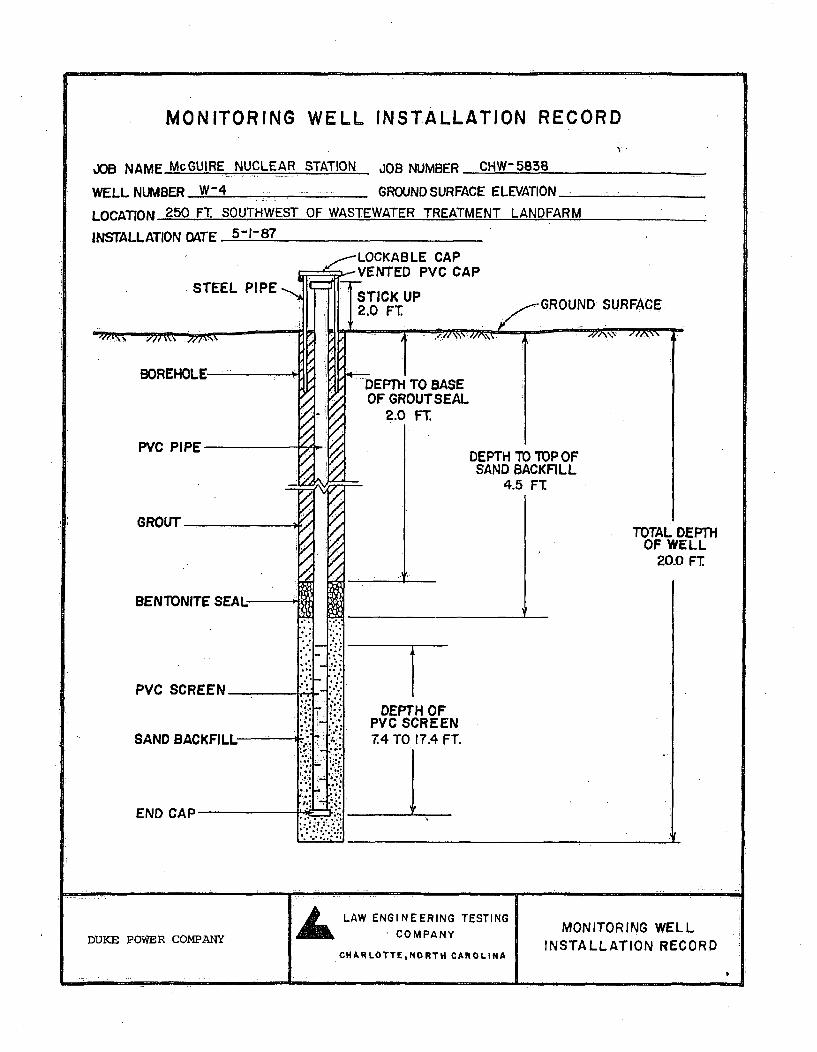
MONITORING WELL INSTALLATION RECORD
JOB NAME McGUIRE NUCLEAR
WELL NUMBER W-4
I nV.^1nI 250 FT SOUTHWEST
STATION JOB NUMBER CHW- 5838
GROUND SURFACE ELEVATION
OF WASTEWATER TREATMENT LANOFARM
INSTALLATION DATE 5-1-87
. STEEL PIPEGROUND SURFACE
PVC PIPE
DEPTH TO BASEOF GROUTSEAL
2.0 FT
DEPTH TO TOPOFSAND BACKFILL
4.5 FT
TOTAL DEPTHOF WELL
20.0 FT
GROUT
BENTONITE
IPVC SCREEN.
DEPTH OFPVC SCREEN7.4 TO 17.4 FT.
LAW ENGINEERING TESTING MONITORING WELL
DUKE POWER COiiPANY COMPANY 1 INSTALLATION RECORDCHARLOTTENORTH CAROLINA
_ _ _ __ _ _ _ _ __ _ _ _ _ __ _ _

MONITORING WELL INSTALLATION RECORD
JOB NAME McGUIRE NUCLEAR STATION JOB NUMBER CHW-5838
WELL NLU1BER W-5 GROUND SURFACE ELEVATION
LOCATION 20 FT. SOUTHWEST OF.WASTEWATER TREATMENT LANDFARM
INSTALLATION DATE 4-30-87
STEEL PIPE
BOREHOLE
PVC PIPE
GROUT
BENTONITE SEAL-------
PVC SCREEN_
SAND BACKFILL-
END CAP
ol
ý2/
-LOCKABLE CAP-VENTED PVC CAP
STICK UP2.0 FT.
GROUND SURFACEL
.e1 N'%,DEPTH TO BASEOF GROUTSEAL
28.0 FT
• "/q \\ %, -- •.I'-x
DEPTH TO TOP OFSAND BACKFILL
30.0 FT.
TOTAL DEPTHOF WELL43.0 FT.
q,,
DEPTH OFPVC SCREEN3-.0T042.0 FT.______L~
J
LAW ENGINEERING TESTING MONITORING WELL
DUKE POWER COMPANY COMPANY
CHARLOTTE,NORTH CAROLINA INSTALLATION RECORD

?,
P Duke-WEnergy.
Duke Energy CorporationEH&S Services13339 Hagers Ferry RoadHuntersvillc, NC 28078
October 7, 2004
N.C. Department of Environment and Natural ResourcesDivision of Water QualityGroundwater Section
RE: Well Construction Records (Form GW-1)
Attached, please find Well Construction Records for twelve (12) monitoring wells/piezometersinstalled at Duke Power's McGuire Nuclear Site between September 23, 2004 and October 4,2004. Each of these wells was installed using Geoprobe® direct push methods with pre-packed wells screens. A diagram of typical well construction is included. The primarypurpose of these wells is for monitoring groundwater elevations in the shallow aquifer at thesite.
If you have any questions concerning these wells, please contact me at 704.875.5228.
Thank You,
Tim Hunsucker, ScientistDuke Power CompanyPC & EHS, Chemical/Physical
attachments
cc: Victor Thompson, Duke PowerMichael, Phillips, Duke Power

McGuire Nuclear StationTypical Geoprobe Well Construction
I Lod" Wd CVp
&wel Wftmlgh Vauft
--- 2" PVC Ca
-Gwct
-San
U1I2ftD~ma&Wo~cee

WELL CONSTRUCTION RECORD
North Carolina - Department of Environment and Natural Resources - Division of Water Quality - Groundwater Section
WEU CONTRACTOR (INDIVIDUAL) NAME (print) TImothy S. Hunsucker CERTIFICATION # 2664
WELL CONTRACTOR COMPANY NAMj E Duke Power Company PHONE # (704) 875-5228
STATE WELL CONSTRUCTION PERMITN NA ASSOClATEDWQPERMIT# NA(if applicable) (if applic•ble)
I. WELL USE (Check Applihable Box): Residential 0 Municipal/Public 0 Industrial 13 Agricultural 0Monitoring W Recovery E3 Heat Pump Water Injection 0 Other 0 If Other, List Use Plezome
2. WELL LOCATION:Nearest Towm: Huntearvlle County Meckdenburg
McGuire Nuclear Station I NC Highway 73 West, 28078
3.
(Sfte Name, Numbea- Communily. Subdivision, Lot No., Zip Code)
OWNER: Duke Power CompanyAddress 422 South Church Street
(Stree or Route No.)Charlotte, N.C. 28242
City or Town State Zip Code
Area code- Phone munber4. DATE DRILLED 9/29/045. TOTAL DEPTH: 24.07 (bgs)6. DOES WELL REPLACE EXISTING WELL? YES 0 NO E37. STATIC WATER LEVEL Below Top of Casing: 17.05 FT.
(Use "+" if Above Top of Casing)8. TOP OF CASING IS 0.35 FT, Above Land Surface*
*Top of easing tenalated attor below land suriaee requires avartance In asecoaeewftt ISA NCAC 2(.0113
9. YIELD (gpm): NA METHOD OF TEST NA10. WATER ZONES (deph): NA
11. DISINFECTION: Type NA Amount NA12. CASING: WaIlThickmess
Depth Diameter or WeigWtFL MvaterialFrom -0.WW To 15.07' Ft 0.5" 'Sdh,0 PVCFrom To FLtFronm• To FLt.
13. GROUT: Depth Material MethodFrom 6" To 11.2' .FL cementgmout p___,___upFrom 11.2' To 13.0' Ft. gimrtrfo _ _
14. SCREEN: Depth Diameter Slot Size MaterialFrom 15.07' To 24.07' Ft. 0.5' in. 0.01 in. PVC*From To Ft in. in.
15. SANDIGRAVEL PACK:Depth Size Material
From 13ff To 24.07' Ft._ nnh allca sandFrom To. Ft
Topographic/Land settingORidge OSlope OValley [lFlat
(check appr•piate box)Latitude/longitude of 5 location
(deweevinnutseoool) 'Latitude/longitude source:OGPSOTopographic map
(check box)DEPT DRILLING LOG
From To Formation DescriptionNA - Well installed using
SWel1.t• Tdrect push menthods. Nocores or cuttings werecoffected.
Show direction and distance In miles fruom at leasttwo State Roads or County Roads. Include the roadnum
Rat
16. REMARKS: "eens am Geoprobe tye prepaked o•reens (0.5': lo X1A" OD) "Flush mourd hntafiaton inwater-tghtvaulL
I DO HEREBY CERTIFY THAT THIS WELL WAS CONSTRUCTED IN ACCORDANCE WITIH ISA NCAC 2C, WELLCONSTRUCTION STANDARDS, AND PT PY OF THIS RECORD HAS BEEN PROVIDED TO THE WELL OWNER
.SIGNAIURE OF PERSON CONSTRUCTING THE WELL / DATE
Submit the original to the Divisinu of Water Quality, Groundwater Section, 1636 Maml Servlee Center. Raleigh, NC27699-1636 Phone No. (919) 733-3221, within 30 day&. OW-1 REV. 0712001

WELL CONSTRUCTION RECORD
North Carolina - Department of Environment and Natural Resources - Division of Water Quality -Groundwater Section
WELL CONTRACTOR (INDIVIDUAL) NAME (print) Throthy S. Hunsucker CERTIFICATION N 2664
WELLCONTRACTOR COMJANY NAME Duke Power Company . PHONE # f704) 875-5228
STATE WELL CONSTRUCTION PERMIT NA ASSOCIATED WQPERMIT# NA(ifaPplieable) (ifaPplicable)
I. WELL USE (Check Applicable Box): Residential 0 Municipal/Public 0 Industrial E0 Agricultural 0Monitoring [: Recovery 0 Heat Pump Water Injection 0 Other 0 If Other, List Use Plezometer
2. WELL LOCATION:Nearest Town: Hunteerslle County Meddenburg
McGulre Nuclear Stalon I NC Higlay 79 West.28078 e,
(Src Name. Numbem Cmmutmity. Subdion, Lo No., Zip Code)
3. OWNER. Duke Power CompanyAddress 422 South Chur•h Street Lat
(Stre or Route No.)Charlotte, N.C. 28242
City or Town State Zip Code Fac-y____Area ode- Phooe, nunker
4. DATE DRILLED 1129045. TOTAL DEPTH: 19.63 (bps)6. DOES WELL REPLACE EXISTING WELL? YES 03 NO I37. STATIC WATER LEVEL Below Top ofCasing: 11.37 FT.
(Use "W if Above Top of Casing)8. TOP OF CASING IS 0.41 Fr. Above Land Surface*
'Top f•easing tenmdiatd a/or below had surface requlees avariance In acordance wth 15A NCAC 2C.011&.
9. YIELD (gpm): NA METHOD OF TEST NA10. WATER ZONES (depth): NA
I1. DISINFECTION: Type NA Amount NA ShI12. CASING: WallThiclness two
Depth Diameter or Weigh . Materal nunFrom -OAI' To 13.-3' Ft. Or5 Sch. 80 PVCFrom To Ft._From To - Ft. -
13. GROUT: Depth Material MethodFrom 6" To 9.5' Ft. ementgrout punm I adam•n• p
From O.N' To 11.r Ft. ,arbW _ _'_
14. SCREEN: Depth Diameter Slot Size MaterialFrom 13.63' To 19.68' Ft 00 ' in. 0.01 in. PVC*From To F. in. in.
15. SAND/GRAVEL PACK:Depth Size Material
From 11.7' To 19.63' Ft. _ - si ncba sand
From To Ft.
TopographiclLand settingOftidge rOSIope OValey WFlat
(ck appropriae bo)Latitude/longitude pfwell location
itudeAongitude source:DGPS0Topographic map
om To
(cheek box)DRILLINOLG
Formation DescriptionNA- Wel Instatled usndirc push metods. Nocores or cutUngs werecollected.
OATIONw direction and'distance in miles from at leastState Roads or County Roads. Include the read
16. REMARKS: "Smnare Geoprmbeypepepad •seeea(0.5":lDX1A'OD) "Flush mount Insiataon Inwater-0ghtvault
I DO HEREBY CERTIFY THAT THIS WELL WAS CONSTRUCTED IN ACCORDANCE WITH 15A-NCAC 2C, WELLCONSTRUCTION STANDARDS, AND TA CO -F THIS RECOR. HAS BEEN PROVIDED TO THE WELL OWNER
/SIWAIURf, OF I ON CONSTRUCTING THE WELL V'ATE
Submit the original to the DlvIoe of Water Quality, Groundwater Section, 1636 Mall Service Center- Raleigh, NC27699-1636 Phonea No. (919) 7334221, within 30 days. GW-I REV. 07/2001

WELL CONSTRUCTION RECORD
North Carolina - Department of Environment and Natural Resources - Division of Water Quality - Groundwater Section
WELL CONTRACTOR (INDIVIDUAL) NAME (p)Q ThkoIIW S. HurnUcker_ CERTIFICATION # 2664
WELL CONTRACTOR COMPANY NAME Duke Power Company PONE 704 875-5228
STATE WELL CONSTUCTION PERMMI NA _ ASSOCIATED WQ PERMIM NA
fif aplicable) (ffapplicable)
1. WELL USE (Check Applicable Box): Residential 01 Municipa•lPublic 0 Industrial IJ Agricultural 0Monitoring IZ Recovery El Heat Pump Water Injection 0l Other 0] If Other, List Use Plezometer
2. WELL LOCATION:Nearest Town: Huntaiar1le, County Mecdenburg
McGuire Nuclear Station I NC Hgway 73 West, 28078
3.
(Stuet Name. Numbe.m Commurnty. Subdivs Lot No, Zip Code)
OWNER: Duke Power CompanyAddress 422 South Church Street
(Sueet or Rote No.)
Topographic/Land settingMRidge OSlope MaVlley 10Flat
(check appropdale box)Latitudeongitude of well location
..•A!,• / to. #,i ? I• (de us/se:30PS as)" map
Latitude/longitude source:OGPSnropographic map
Charlotte, N.C. 28242City or Town Stale Zip Code
Area code- Phone modoer4. DATE DRILLED 092M45. TOTAL DEPTH: 24.12 (bgs)6. DOES WELL REPLACE EXISTING WELL? YES £1 NO E37. STATIC WATER LEVEL BelowTop of Casing: 2023 FT.
(Ue "+" if Above Top of Ctsing)8. TOP OF CASING IS - 0.45 FT. Above Land Surlfhe*
*Top ofcstng tenrmhated atior below land surface requires avariance In seordame with 15A NCAC 2C .011&
9. YIELD (gpm): NA METHOD OF TEST NA10. WATER ZONES (depth): NA
i1. DISINFECTION: Type NA Amount NA12. CASING: Wall Thidmess
Depth Diameter or Weight/FL MaterialFrom -0.45' To 18.12' Ft. 0.5' s80.W PVCFrom To Ft.From To- FL.____
13. GROUT: Depth Material MethodFrom W" To 13A2' Ft oementrolut pwots Ibo~t 4pFrom 13.4Z To 15.82' Ft. 0MWarbenMto _
14. SCREEN: Depth Diameter Slot Size MaterialFrom 18.12' To 24.12 Ft. 0f In. 0.01 in. PVC"From To Ft. In. in.
15. SAND/GRAVEL PACK:Deph size material
From 15.52' To 24.12' Ft. s -,, lca sandFro.n. To Ft.. _
From
.WelT, .
(check boor)DRILLING LOG
To Formation DescriptionNA- WeD intaed usndirect psh methods. Nocores or cutfngs werecoleed.
LOCATION SKETCHShow direction and distance in miles from at leasttwo State Roads or County Roads. Include the roadAum TAn
.~ 1~
16. REMARKS: *SMeMare aaGeopsbe ypetrPaCkedesMn(0.': lDX 14'OD) *FlushrnourinsalationInwaar-tightvau[L
I DO HEREBY CERTIFY THAT THIS WELL WAS CONSTRUCrED IN ACCORDANCE WITH 15ANCAC 2C, WELLCONSTUCnON STANDARDS, AND THAT CO F THIS RECO HAS BEEN PROVIDED TO THE WELLD OWNER
Submit the original to the Division of Water Quality, Groundwater Section, 1636 Mail Servyke Center-Raleigh, NC27699-1636 Phone No. (919) 733-3221, within 30 days. GW-I REV. 07/2001

WELL CONSTRUCTION RECORD
North Carolina - Department of Environment and Natural Resources - Division of Water Quality - Groundwater Section
WELL CONTRACTOR (INDIVIDUAL) NAME (print) Tkmdthy S. Hunsucker CERTIFICATION If 2664
WELL CONTRACTOR COMPANY NAME Duke Power Company PHONE # (704 875-228
STATE WELL CONSTRUCTION PERMIT0 NA ASSOCIATED WQ PERMIT NA(if applicable) (if applicable)
1. WELL USE (Check Applicable Box): Residential 0 Municipal/Public 0 Industrial 0 Agricultural [0Monitoring M. Recovery 0 Heat Pump Water Injection 0 Other 0] If Other, List Use Piezoieter
2. WELL LOCATION:Nearest Town: Huntrf,,rrle County. Mecdenburg
McGulra Nuclear Station I NC Highway 73 West, 28078(Street Niame. Numbeis, Cmmtiy. Subdivision, Lot No.. Zip Code)
3. OWMAddi
1R. Duke Power Companytess 422 South Church Street
(Shreet or Route No.)Charlotte. N.C. 28W
City or Town State Zipi242code
Are code Ph.one numnb4. DATE DRILLED 1014/045. TOTAL DEPTH6 18.65 (bgs)6. DOES WELL REPLACE EXISTING WELL? YES 03 NO Ml7, STATIC WATERLEVEL BelowTopofCasing: DRY FT.
(Use "V+ if Above Top of Casing)8. TOP OF CASING IS "-0.45 FT. Above Land Surface*
*Top ofesstag terminated at/or bew land urfsee scquim avariance In accordance witb 1•A NCAC 2C.8118.
9. YIELD (gpm): NA METHOD OF TEST NA10. WATER ZONES (depth): NA
It. DISINFECTION: Type NA Amount NA12. CASING: Wanl Thidcness
Depth Diameter or Weight/FL MaterialFrom -0.4&' To 15.65' Ft. 0.5' SdL 0 PVCFrom To Ft._From To Ft.
13. GROUT: Depth Material MethodFrom 6" To 10.85' Ft. conmwon PAeadnoamt,,
From 10.85' To 13.25' FL gnmWubeanone14. SCREEN: Depth Diameter Slot Size Material
From 16.65' To 18.85' t 0.5' fIn. 0.01 in. PVC*From To Ft. in. in.
15. SAND/GRAVEL PACK:Depth Size Material
From 13.25' To 18.65' FL m_-Omme silkiadFrom To Ft.
Topographic/Land settingiRIdge MSlope OIValley IMFlat
(dweck appruno box)Latitude/longltudp ofwell location
ON A M ml Wt(deg.reson-wtest-occds)
Latitude/longitude source:OGPSnTopographic map(check box))
DEPTH DRILLING LOGFrom To Formation Description
NA - Well Iktalled usingWeIT .. direc push meftds. No
cores or cuttings werecollected,
LoCATiON SKETCHShow direction and distance In miles from at leasttwo State Roads or County Roads. Include the road
numb a = A
16. REMARKS: *Siens aie Geopube type prepled screen (0.5': IO X 1.4' OD) "Flush mount installatmor In water-lfght vaulL
I DO HEREBY CERTIFY THAT THIS WELL WAS CONSTRUCTED IN ACCORDANCE WITH. 15A NCAC 2C, WELLCONSTRUCTION STANDARDS, AND THAT PY OF THIS REORD HAS BEEN PROVIDED TO THE WELL OWNER
"' ( - -/ S]GN(ATU•OFI'EISO•ICONSTRUCTINGTHEWELL ' -" DATE
Subutlt the original to the Division of Water Quality, Groandwater Sectwon, 1636 Mall Service Ceater- Raleigh, NC27694-1636 Phone No. (919) 7W3-3211, within 30 dayL GW-1 REV. 07/2001

WELL CONSTRUCTION RECORD
North Carolina - Department of Environment end Natural Resources - Division of Water Quality -Groundwater Section
WELL CONTRACTOR (INDIVIDUAL) NAME (print) lrhothy S. Hunsucker CERTIFICATION # 2864
WELL CONTRACTOR COMPANY NAME Duke Power Company -PONE N (704') 875-5228
STATE WELL CONSTUCION PERMI'T NA ASSOCIA4TED WQ PERIAT# NA
(ifaplicable) (if aslicable)
1. WELL USE (Check Applicable Box): Residential 0 Municipal/Public 0 Industrial 0 Agricultural 0Monitoring 19 Recovery 03 Heat Pump Water Injection El Other 0 If Other, List Use Piezometer
2. WELL LOCATION:Nearest Town: HuntreMvia County. Mecldnbýg
McGuire Nuclear Station I NC Highway 73 West. 2807M
3.
(Se Ne. N wNumbem Com• qty. SubdivWo. Lot No.. Zip Code)
OWNER: Duke Power CompanyAddress 422 South Church Street
(Suet or Route No.)Chalot, N.C. 28242
City or Town Stue Zip Code
Area cde- Phoes wmber4. DATE DRILLED 9/241045. TOTAL DEPTH: 18.78 (bgs)6. DOES WELL REPLACE EXISTING WELL? YES El NO Wl7. STATIC WATER LEVEL Below Top of Casing: DRY FT.
(Use'+" If Above Top of Cadig)8. TOP OF CASING IS - 0.38 FT. Above Land Surface*
'Top of casing nm•boted attor below ld stue rquift avarianee I accordaace with ISANCAC 2C.0l1&
9. YIELD (gpm): NA METHOD OF TEST NA10. WATER ZONES (depth): NA
11. DISINFECTION: Type NA Amount NA12. CASING: Wall Thidmess
Depth Diameter or WdgF MaterialFrom -0.38' To 12.78' Ft. 0.5O Sd .8 PVCFrom - To Ft_From To_ Ft. -
13. GROUT: Depth Material MethodFrom 8' To 6.42' Ft. Mment9gout p dmd IbteenLpFrom 8.42' To 10.82 FLt•. drbeloewte
14. SCREEN: Depth Diameter Slot Sie MaterialFrom 12.78' To 18.78' Ft. 0.5O In. 0.01 in. PVC'From To Ft in. _ In.
15. SAND/GRAVEL PACK.Depth Sim Material
From 10.82' To 117 Ft. FL 4 - dlc sandFrom To Ft_
Topographic/Land settingORidge OSlope OValley *Fiat
(dchck aWopise box)Latitudelou n of well location
Latitude/longitude source:OOgPSOTopographic map(chwk box)
From To Formation DescriptionNA - WOO nstalle u
wel T47:' dirct push nmthoeA Nocores or cuttings were
____ ____ collected.
LOCATION SKETCHShow direction and distance in miles from at leasttwo State Roads or County Roads. Include the roadnumaans
* t~ ~-
* C
16. REMARKS: *Sme are Geo yprobe l pmpackd ad ens (0.5': ID X 1.4 OD) "Flush mount ingaation inwater-tight vault.
I DO HEREBY CER•IFY THAT THIS WELL WAS CONSTRUCTED IN ACCORDANCE WITH 15A NCAC 2C, WELLCONSTRUCTION STANDARDS, AND TTA YF THIS HEC hAS BEEN PROVIDED TO THE WELL OWNER
.... .... /I(NATM05O PERSOMMCOSTRUC/'NO THE WELL ""DATE
Submit the original to the Division of Water Quality, Groundwater Section, 1636 Mall Service Center -Ratlegh, NC27699-1636 Phone No. (919) 733-3221, within 30 days. GW-I REV. 07/2001

WELL CONSTRUCTION RECORD
North Carolina - Department of Environment and Natural Resources - Division of Water Quality - OGradwater Section
WE.LL CONTMACTOR (N• IJVDAL) NAME (pri0t) Thilt S. Hunsuckor CERTIFCATIONC 2684
WELL CONTRACTOR COMPANY NAME Duke Pwer Company PHONE # f704) 875,5M8
STATE WELL COmmTucINm PERMIT NA _ _ASSOCIATED WQ PERM~rr# NA(if saplicable) (ifapplicable)
1. WELL USE (Check Applicable Box): Residential 0 Municipal/Public r3 Industrial 03 Agricultural 0Monitoring l Recovery 13 Heat Pump Water Injection E Other 0 If Other, List Use P romete
2. WELL LOCATION:Nearest Town: HuntOrMVUIO County MedderburgMcGuie Nuclear Station I NC Highway 73 West, 28078
3.
(Sti( Namw. Ne•nbeM CommitY, Subdivisim•o t No.. Zip Code)
OWNER: Dui Power CompanyAddress 422 South Church Street
(Sineler Reo*No.)Charlotte, N.C. 26242
City or Town State Zip Code
Anm code-. PIWW num•b
4. DATE DRILLED 10141045. TOTAL DEPTH: 24.0 (bgs)6. DOES WELL REPLACE EXSTING WELL? YES 0 NO R]7. STATIC WATER LEVEL Below Top ofCasing: 22.91 Fr.
(Une "+" IfAbow Top of CasW8. TOP OF CASING IS ""0.39 FT. Above Land Surfce*
*Top Ofcasheagemuniuted at/or bklow bad suri reqrm avarhact. In wontutWit 315A NCAC 2C.01I&
9. YIELD (gpm): NA METHOD OF TEST NA10. WATER ZONES (depth):_ _ _
It. DISINFECTION: Type NA Amount NA12. CASING: Wall rhickness
Depth Dkitieter or WeWRtlt MateriaFrom -0-SV To 18.q FL B 0di So0 PVCFrom To FLtFrom To FL_
13. GROUT: Dept material MethodFrom (r To 13.' Ft. cement gWrout __T__t_
From 13,7 To 16.1' FL Otirm eirboam14. SCREEN: Depth Diamnter Slot Size Material
Fromt 18.0' To 24.0' Ft. 0.5" - ., 0.01 in. PVC'
From To Ft. in. In.IS. SAND/GRAVEL PACK:
Depth sine MaerialFrom 16.1' To 24.V Ft. m "mwi slica sandFrom To Ft_
Topogmphic/land settingORidge OSlope OValley OFlat
(c-k WrmaWi box)Latitude/longitude of well location
Latitude/longitude source:OG'PSCITopographic map(check box)
DDRILLING LOGFrom To Formation Description
NA -Wel Ihvafld usingWeo T4- eodret push menxthod No
__ res or cuttings were
Show direction and distwine in miles from at leasttwo State Roads or County Roads. Include the road
16. REMARKS: Srmns am GeoPobe tXe1 Pr cred aens (0,5 ID X IA" 00) "Flush ount nkateletion In water4ight vault
I DO HEREBY CERTIFY THAT THIS WELL WAS CONSTRUC1ED IN ACCORDANCE WrIH ISA NCAC 2C, WELLCONSTRUCTION STANDARDS, AND OFHAT THIS OT ORD HAS BEEN PROVIDED TO THE WELL OWNER
,- S •LTURE OF PERSON CONSTRUCIING THE WELL • DATE
Submit the orIginaI to the Divhion of Water Quality, Groundwater Section, 1636 Mail Service Center - Raligh, NC27699-1636 Phoa No. (919) 733-3221, within 30 dazy OW-i REV. 07t2001

WELL CONSTRUCTION RECORD
North Carolina - Department of Environment and Natural Resources - Division of Water Quality - Groundwater Section
WELL CONTRACTOR (INDIVIDUAL) NAME (print). Tkothy S. Hurnmcker CERTIFICATION # 2664
WELL CONTRACTOR COMPANY NAME Duke Power Company PHONE is (704) 875-5228
STATE WELL CONSTRUCTION PERMITI NA _ASSOCIATED WQ PERM~rI# NA(if applicable) (if applicable)
1. WELL USE (Check Applicable Box): Residential 0 Municipal/Public 0 Industrial 03 Agricultural []Monitoring M Recoveay 0 Heat Pump Water lInjection 0 Other Q If Other, List Use Piezoneter
2. WELL LOCATION:Nearest Tom: Huntumuvi. County Mecionburg
McGulre Nuclear Station I NC Highway 73 West, 28078(Sfte Name, Numbcs Community, Stdlviso, Lot No.. Zip Code)
3. OWNER: Duke Power CompanyAddress 422 South Chtuch Street
(Stue or Rouft No.)Chalolle, N.C, 28242
City orTom Ste Zip Code
Arm oode Phone number4. DATE DRILLED 902M045. TOTAL DEPTH: 20-23 (bgs)6. DOES WELL REPLACE EXISTING WELL? YES 0] NO El7. STATIC WATER LEVEL Below Top of Casing 18-24 FT.
(Use -+" if Abov Top of Casng)8. TOP OF CASING IS - 0.31 FT. Above Land Surface*
*Top ofcasing ohwtntd atar below land warface eqim avarance In accordance wift ISA NCAC 2C .011&
9. YIELD (gpm): NA METHOD OF TEST NA10. WATER ZONES (depth): NA
11. DISINFECTION: Type NA Amount NA12. CASING: Wall Thidmess
Depth Diameter or Wet/FtL MaterialFrom -0.31- To 11.23' Ft. 0.56 SdrO PVCFrom. To FL.From To FLt
13. GROUT: Depth Material MethodFrom 6" To 7.13' Ft. ementtgmut vim dwbolumup
From 7.13' To 9.3' Ft. -mtarbAntant14. SCREEN; Depth Diameter Slot Size Material
From 11.23' To 2023' FL 0.5" in, 0.01 In. PVC'From To Ft. in. In,
15. SAND/GRAVEL PACMDepth size Material
From 9.53' To 202'. Ft._ 2Mw dice sandFrom To Ft.
Topographic/Land settingORidge OSlope OValley WFlat
(dak appMroxt box)Latitude/longitude of well location
(degre/mntesaecah)
Latitude/longitude sourne:OGPS0Topographic map(chck b-)
DEPTH DRILLING LOGFrom To Formation Description
NA- W uMta tusi-g,WelT-- dec•, push methods. No
pcres or outings warecolected.
LOCATION SKETCHShow direction and distance In miles from at leasttwo State Roads or County Roads. Include the road
16. REM&ARKS: *eens me Gepprobe typerppackedaemens (0;: OX l.4' OD) Flsh mounx nstalation in water-tght vault.
I DO HEREBY CERTIFY THAT THIS WELL WAS CONSTRUCTED IN ACCORDANCE WITH 15A NCAC 2C, WELLCONSTRUCTION STANDARDS, AND THAT A (OP? OF THIUS HAS BEEN PROVIDED TO THE WELL OWNER
. IW(A"U OF PERSON CONSTRUCTING THE WELL DATE
Submit the original to the Division of Water Qualt, Groundwater Section, 1636 Mail Service Center- RAleigh, NC27699-1636 Phone No. (9•1) 733-3221, within 30 dayL GW-I REV. 07/2001

WELL CONSTRUCTION RECORD
North Carolina - Department of Environment and Natural Resources - Division of Water Quality - Groundwater SectionWELL CONTRACTOR (INDlVIDUAL) NAME (priut) Timoty S. HunsucIer CERTIFICATION N 2664
WELL CONTRACTOR COMPANY NAME Duke Power Company ._ No (704) 875"5228
STATE WELL CONSTRUCMON PERMrM NA ASSOCIATED WQ PERMM NA(if applicable) (If alicable)
1. WELL USE (Check Applicable Box): Residential 0 Municipal/Public 03 Industrial 0 Agricultural 0Monitoring 1 Recovery 0 Heat Pump Water lroection 0 Other 0 If Other, List Use Plzometer
2. WELL LOCATION:Nearest Town: Huntersvfe County MCdde•bi
McGuie Nudear St•aion I NC Hghway 73 West 28078(Street Name. Nwabe Cmozounty, Subdivisfko LAt No.. Zp Code)
OWNER: Duke Power CompanyAddress 422 South Church Seet
(Soet or Route No.)Chardotte, N.C. 28242
City or Town Stale Zip Code
Area code- Ph= enber4. DATE DRILLED .9O3J045. TOTAL DEPTH: 20.01 (bgs)6. DOES WELL REPLACE EXISTING WELL? YES r3 NO 917. STATIC WATER LEVEL Below Top of Casing: 14.49 FT.
(Use-+" if Above Top of Calug)8. TOP OF CASING IS 0.28 FT. Above Land Surfaces
*Top of uming teriatul -oior below kad nrfae• wrquire aw .arluee in acowduce wih ISA NCAC 2C.01I.
9. YIELD (gpma): NA METHOD OF TEST NA10. WATER ZONES (depth): NA
11. DISINFECTION: Type. A Amount NA12. CASING' Wall Thickness
Depth. Diameter or WeigF MaterialFrom -0.28' To 11.01' Ft. 0." Sch.60 PVCFrom To FLt.From_ To Ft.
13. GROUT: Depth material MeodFrom I' To 7,61' Ft. men grout pwoadibatqWFrom 7.61' To 9.01 Ft. gmnibzftVe _
14. SCREEN: Depth Dianeter Slot Size MaterialFrom 11.01' To 20.01' Ft. O.5" in. 0.01 in. PVC'From To FL In. In.
15. SAND/GRAVEL PACK:Depth Sime material
From 9.01' To 20.01' FLt •00o • utica sandFrom To Ft_
Topographic/Land settingORidge O3Slope OValley OFlat
(dcek %aVopaw box)Latiudelon • e of well location
Latitude/longitude source:0GPSOTopographic map(chokbox)
DE DRILLING LOGFrom To Formation Description
NA- WeD Irmtelled usngWel T-10. ..direct push methods. No
cores or utOngs were___ collected.
LOCATON 99=Show direction and distance in miles from at leasttwo State Roads or County Roads. Include the road
16. REMARKS: "Sreer am Geopm-be t/ prepacod amem (0.5': IDX 1A* 00) "Flush mount WKatan in water4igt vault
I DO HEREBY CERTIFY THAT THIS WELL WAS CONSTRUCTED IN ACCORDANCE WITH ISA NCAC 2C, WELLCONSTRUCTION STANDARDS, AND TA Y OYF THIS RECORD HAS BEEN PROVIDED TO THE WELL OWNER
" - A/ STG1ATORE O•PERSON CONSTRUCTING THE WELL 'DATE
Submit the original to the Dlhslon of Water Quality, Groundwater Section, 1636 Mail Senic Ceoter- Raledgh, NC27699-1636 Phone No. (919) 733-3221, within 30 dayL GW-1 REV. 07/2001

WELL CONSTRUCTION RECORD
North Carolina - Department of Environment and Natural Resources - Division of Water Quality - Groundwater Section
WELL CONTRACTOR MINDIVD)UAL) NAME (print) ThiMy S. HunMuckOr CERTIICATION # 2664
WELL CONTRACTOR COMPANY NAME Duke Pow Company PHONE N (704] 875-6228
STATE WELL CONSTRUCTION PERIU'4lY NA -ASSOCIATED WQPERMIT NA(ifspplicable) (if applicable)
1. WELL USE (Check Applicable Box): Residential 0 Municipal/Public 0 industrial 12 Agricultural 0Monitoring W] Recovery 03 Heat Pump Water Injection I) Other 03 If Other, List Use PW=mtr
2. WELL LOCATION:Nearest'Town: HuntersUlle County Moddenbuw
MoGuke Nudear Station / NC Highway 73 West, 28078(Strum Nmne, Numben Community. Subdivion, Lot No., Zip Code)
OWNER: Duke Pow CompanyAddress 422 South Church Street
(Srt orlRoute .No.)
Topographic/Land settingORidge OSlope (]Valley OFlat
(chek APPropde box)Latitude/longitude ofwell location
3%4 . -A n W(desourmc:ftPS/copog)
LatitudeAongitude source:OOPSlJTopographic map(chmt hrff)
Chawoft, N.C. 28242City or Town Stue Zip Code
Ana code- Phone number4. DATE DRILLED 9223045. TOTAL DEPTH: 18.74' (bgs)6. DOES WELL REPLACE EXISTING WELL? YES 0 NO 137. STATIC WATER LEVEL Below Top of Casing: _ 12A2 FT.
(Us-+- if Above Top of Casing)8. TOP OF CASING IS 0.32 FT. Above Land Surface*
*Top ofcasing kamad al or below lad arfam requis avariance In accordance with ISA NCAC 2C .011&.
9. YIELD (gpm): NA METHOD OF TEST NA10. WATER ZONES (depth): NA
11. DISINFECTION: Type, NA - Amount NA12. CASING: Wall Thidmes
Depth Diameter or Weight/FL MaterialFrom -0.32 To 9.74 Ft. 5o. $Ch.so0 PVCFrom - To Ft.From To Ft._
13. GROUT: Depth Material MethodFrom 6" To .84 Ft Cmwntgrout ______u_
From S.64' To 7.84 Ft. grsuiarbwot*.14. SCREEN: Depth Diameter Slot Size Material
From 9.74' To 18.74' Fpt 0.5 in. 0.01 In. PVc'From To Ft. In. in.
15. SANDIGRAVEL PACK:Depth Sie Material
From 7.84 To 18.4' Ft._M om sifts randFrom To FL.
From To
Wel TI.:
DRILLING LOGFormation Description
NA -W.Il kistald unindrct push metds. Nocorns or aftngo werecoleted.
LOCATION SKETCH
Show direction and distance In miles from at leasttwo State Roads or County Roads. Include the road
1-4~
16. REMARKS: aSmee e Geooube-m epnaMed swen (0.5': ID X 1.4"OD) Fluh mountx tataon In watrt•tvau
I DO HEREBY CERTIFY THAT THIS WELL WAS CONSTRUCTED IN ACCORDANCE WITH I5A NCAC 2C, WELLCONSTRUCTION STANDARDS, ýAN7D TAT A nOF TFUHS HAS BEEN PROVIDED TO THE WELL OWNER
.S INRlJIE-OF PERS CONSTRUCTING THE WELL ' DATE
Submit the original to the Dhdslon of Water Quality, Groundwater Section 1636 Mail Service Cester - Raleigh, NC276"-1636 Phone No. (919) 7W3221, within 30 days. (W-i REV. 07/2001
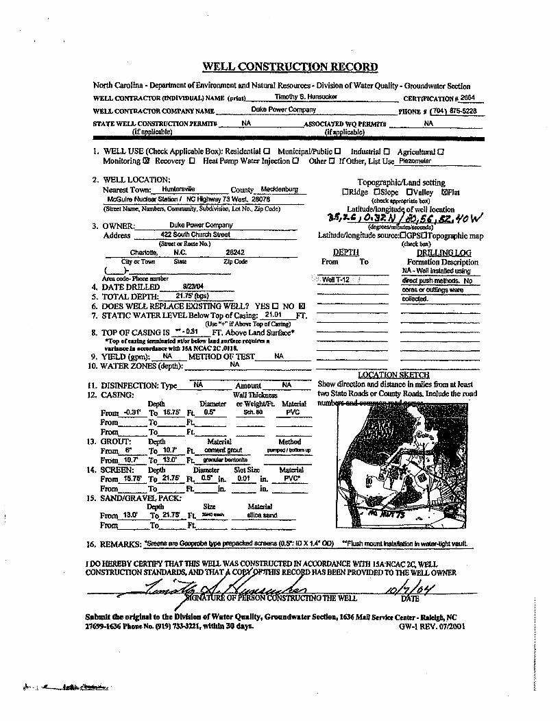
WELL CONSTRUCTION RECORD
North Carolina - Department of Environment and Natural Resources- Division of Water Quality - Groundwater Section
WELL CONTRACTOR (NDIVIDUAL) NAME (plint) Timothy S. Hunsucker CERTIFICATION # 2684
WELL, CONTRACOR COMTANY NAME Duke Power Company pHONE o (704) 875-5228
STATE WELL CONSTRUCTION PERMI1 . NA ASSOCIATED WQ PERMrTr NA(if applicable) (ifapplicablel
1. WELL USE (Check Applicable Box): Residential 0 Municipal/Public 0 Industrial 0 Agricultural 0Monitoring 10 Recovery 0l Heat Pump Water Injection 0 Other 13 If Other, List Use Piezomewer
2. WELL LOCATION:Nearest Town: Hunwvie County Mecidenbuig
McGulm Nuclear Station I NC Highway 73 West, 28078(Strec Name. Numbers, Community. Subdivision, Lot No., Zip Code)
3. OWNER:Address
Duke Powe Company422 South Church Shreet
(RSoet or Routef No.)Charlotte, N.C.
City or Tomi Stme28242Zp Code
Area code- Phone nmiber4. DATE DRILLED 9r23/045. TOTAL DEPTH: 21.75' (bgs)6. DOES WELL REPLACE EXISTING WELL? YES 0 NO El7. STATICWATERLLEVELBelowTopofCasing. 21.01 FT.
(Use "+" if Above Top of Casing)8. TOP OF CASING IS - 0.31 FT. Above Land Surfice*
*Tup of caing ternnnAted at/or below laud surbce reqaires avariance in scoo.am wftb 15A NCAC 2C.018.
9. YIELD (gpm): NA MEiTOD OF TEST NA10. WATER ZONES (depth): NA
11. DISINFECTION: Type NA Amount KA12. CASING: Wall Thidmess
Depth Dimer c.Weightfit. MaterialFrom -0.31' To 15.75' Ft 0.5O Sc. 80 PVCFrom To FLtFrom To Ft. -
13. GROUT: Depth Material MethodFrom 6" To 10.T F't OeMaett grout M Idom upFrom 10.7' To 13.0' FLt erarbonlta
14. SCREEN: Depth Diameter Slot Size MatrialFrom 15-75' To 21.75' Ft. 05 In. 0.01 in. PVC,From To FLt i. in._
15. SAND/GRAVEL PACK:Depth Sin Material
From 13.0' T0 21.75' Ft._ m h dlca sandFrom To Ft_
Topographic/Land settinglJRidge OSlope OValley WFlat
(check appopriate box)Latltude/longitudq of well location
Latitude/longitude source:rIGPSflTopographic map(check box)
METE DRILLING LOGFrom To Formation Description
NA - Well installed usingWell T-A2 direct push methods. No
cores or cutings werecollectd.
LOCATION SKETCHShow direction and distance in miles from at leasttwa State Roads or County Roads. Include the roadnumbb s e"il 1, e poq
16. REMARKS: afarmGeoprbe eprepackad saIeens(0.5:lDX1.4O0) "Flkshamountbnitallatlonwater-tightvault,
I DO HEREBY CERTIFY THAT 11S WELL WAS CONSTRUCTED IN ACCORDANCE WrM 15A-NCAC 2C, WELLCONSTRUCTION STANDARDS, AND THAT CO M RECO HAS BEEN PROVIDED TO WE WELL OWNER
-"- .... /1"UNATUMR OF- MP.SONIM'STRUC'ING THEWELL - "AIE"
Submit the original to the DWvison of Water Quality, Groundwater Sedtion, 1636 Mall servke Center- RaleIgh, NC27699-1636 Phone No. (919) 7W3-3221, within 30 days. GW-I REV. 07/2001

WELL CONSTRUCTION RECORD
North Carolina - Department of Environment and Natural Resources - Division of Water Quality - Groundwater Section
WEL• CONTRACTOR (INDIVIDUAL) NAME (pUint) Tnohy S. Hum* e CERTIFICATION. 28..
WELL CONTRACTOR COMPANY NAME Duke Power Comnpny PONE # (7041 67&-5228
STATE WELL CONgRucfloN PERI~fW NA - ASOCITEDWQ PERnvM NA(if a licable) (if applicable)
I. WELL USE (Check Applicable Box): Residential 03 Municipall/Public 0 Industrial 0 Agricultural 0Monitoring: M Recovery E Heat Pump Water Injection 0 Other3 If Other, List Use Plezome
2. WELL LOCATION:Nearest Town: HunUteMvM County Meebu* r
MoGumhuNudeast ationi NCHighwa73West, 28078(Suet Nxme, Nmben, Commu•ity, Subdilvio, Lot No., Zip Code)
3. OWNER:- Duke Power CompenyAddress 422 South Church Street
(Stret or Route No.)Chaslotte, N.C. 28242
City or Town Std Zip Co
AMUa rode- Phone mmbe:4. DATE DRILLED 0/23/045. TOTAL DEPTH: 14,85' (bgs)6. DOES WELL REPLACE EXISTING WELL? YES 3 NO l7. STATIC WATERLEVELBelowTopofCasing: DRY Fr.
(Use i' if Above Top of CxsiW8. TOP OF CASING IS - 0.30 FT. Above Land Surlace*
*TDp of cashgtuulaueds atd el bud dmrbc t&uras avariace u atewdasetwith ISA NCAC CAII&.
9. YIELD (gp1m): NA METHOD OF TEST NA10. WATER ZONES (depth): NA
11. DISINFEC'TION: Type NA Amount NA12. CASING: Wall Thickness
Depth Diamete or Weigftft MateialFrom -0.30' To 1185' Ft. Of5 Sch.8O PVCFrom To Ft.From To Ft.
13, GROUT: Depth Material MethodFrom 8" To 7.W' Ft. cementgrout p'A,1admut pFrom 7.W5' To 9.85' Ft. Ug Wbuilrt ke
14. SCREEN: Depth Diameter SlotSize * MateralFrom 118 To 14.85' Ft 0.6" iL 0.01 IL PVC*
From To Ft. in. 111415. SAND/GRAVEL PACM
Depth sin MasFrom 9,85' To 14.85' Ft._ mama* sicawFrom To Ft.
Topogmphic/tand settingMiRdge OlSlope MValley MFlat
(check appvpd box)Latitude/iongiltue of well location
Latitude/longitude souroe:lGPSOTopographic map(cheek box)
DE-PTH DRILLIN LO2QFrom To Formation Description
___________ NA - Wed k*WaUtale snWel T-13 ~d~ictpu 22m•Methods. No
_oms or cu~ro weecolected.
Show direction end distance in miles from at leasttwo State Roads or County Roads. Include the radaui
Ali'
* ~'r ~
16. REMARKS: "•&us amGeoprob.tf ipmpoad eoeem(0.5•:loX1A4OD) "Fkh mount nstaailon hI water-tightvauaL
I DO HEREBY CERTIFY THAT THIS WElL WAS CONSTRUCTED IN ACCORDANCE WITH ISA NCAC 2C, WELLCONSTRUMCION STANDARDS, AND rHA OPY OF THIS RECORD HAS BEEN PROVIDED TO THE WELL OWNER
. ... / rSf(GNATI-RETOF PERSON CONSTRU-CTINTHE WEM - DATE--
Submit the eruginal to the Division of Water Quality, Groundwater Section, 1636 Manl Senke Ce2ter- Ralegh, NC27699-1636 Thome No. (919) 733-3221, wftk 30 days. GW-i REV. 07/2001

WELL CONSTRUCTION RECORD
North Carolina - Deprtment of Environmmat and Natural Resources - Divislon of Water Quality -Groundwater Section
WELL CONTRACTOR (INDIVIDUAL) NAME (prid) T.... h S. Huncker CERTIFICATION # 2084
WEIL coNTRACTOR COMPANY NAME Duke Powor Company PoHNE i (t04) 8754228STATE WELL CONwmUCTION PERMIT# MA ASSOCIATED WQ PERMmT# NA
(if applicable) (if applicable)
I. WELL USE (Check Applicable Box): Residential 0 Municipal/Public 0 Industrial 0 Agricultural EMonitoring l Recovery 0E Heat Punp W-ater Injection 0 Other 0 IfOther, List Use Pozmer
2. WELL LOCATION:Nearest Town: Hu wardai County, Mo•enbug
Mc(ut Nuder Saton I NC Hi-hway 73 West, 28078
3.
(Std Name. Numbem Commug . Subvis&k. L No.. Zip Code)
OWNER: Due Power Co"MaAddress 422 South Church strtw
(Slt re RloteNo.)Chrott, N.C. 28242
city or Town Stat Zip Code
Aria €ea- Photn mnuner4. DATE DRILLED 10/4104S. TOTAL DEPTH: M ' (be)6. DOES WELL REPLACE EXISTING WELL? YES 0 NO Ml7. STATIC WATER LEVEL Below Top of Casng. 5.61 FT.
(Use -+ ifAbove Top of Caiag)8. TOP OF CASINO IS "-0.31 FT. Above Land Surface*
*Top ofefing termlated aer below land surface requiesn avariae io savn0ia wft ISA NCAC 2C AlM.
9. YIELD (gpm): I NA METHOD OF TEST NA10. WATER ZONES (depth): NA
11. DISINFECTION: Type NA Amount NA12. CASING. Wall Thidmew "
Depth Diamacr or WeWit MftraFrom -0.31' To 1625' Ft. O..5 Seh. o PVCFrom To FLtFrom To Ft._
13. GROUT: Depth Material MethodFrom 6" To 11.55' Ft. lW mmrUt WIbpnamFrom 11.8' To 15.75' FL wafliubet_•,
14. SCREEN: Depth Diameter Slot Sire MateiaFrom 1825' To 2225' It. 0.5" in. 0.01 in. PVC'From To FL In. in.
15. SAND/GRAVEL PACKIDepth Sin Material
From 13.7V' To 2225' FL ft-l~fit a ¢ sendFrom To Ft.
TopographicLaand setting[:Ridge MSlope MValley IMFlat
(dheck %mpdW box)Latitude/longitude of well location
Latitude/longitude source:00PSOTopographic map(e-* box)
DR aLuNO LOG
From To Formation DescriptionNA- W4 ksWaled usin
WWell 7- dlred p!!Lh methods. No
LOCAT70N SKETCH-
Show direction and distance in miles from at leastwo Stale Roads or County Roads. Include the roadnum . M4 GRM2 -n Bo
16. REMARKS: "SMn am GepOb'b 4p Pedzd • mee (0.5': lOX I." 00) -:ukl1 m ounkstaflafo in w!tr.41t vault.
I DO HEREBY CERTIFY THAT THIS WELL WAS CONSTRUCTED IN ACCORDANCE WITH I1A'NCAC 2C, WELLCONSTRUCTION STANDARDS, AND ~ ~YTý/OP OF THIS RES9RD HAS BEEN PROVIDED TO THE WELL OWNER
S -r/ SI AMUREOF PERSON-CONSTRUCING THE WELL X 'DATE
Submit the original to the Divsion of Water Quality, Groundwater Section, 1636 Mall Servike Ceater. RakIgh NC2769-1636 Pho No. C19) 736 1I, within 30 daoyu OW-I REV. 07/2001
0k- A__ ke%
May 7, 2007
Mecklenburg County Health DepartmentLand Use & Environmental Service AgencyGroundwater & Wastewater Services700 North Tryon Street, Suite 211Charlotte, North Carolina 28202
Reference: NON-RESIDENTIAL WELL CONSTRUCTION RECORDS - SUBMITTAL #1McGUIRE NUCLEAR STATION12700 Hagers Ferry RoadHuntersville, North CarolinaWell Application Permit No. 70000752S&ME Project No. 1264-06-724
Ladies and Gentlemen:
On behalf of Duke Energy, S&ME, Inc. (S&ME) is submitting the enclosed Monitor Well Registrationform and completed/signed Non-Residential Well Construction Records for the following seven (7)groundwater monitoring wells installed at the McGuire Nuclear Station (MNS) site:
• M-82 • M-103• M-84 e M-103R• M-84R • M-104R.* M-85
Duke Energy is voluntarily installing groundwater monitoring wells at MNS as part of a site-widehydrogeologic evaluation. S&ME will submit these Non-Residential Well Construction Records on aperiodic basis as well installations are completed, this being the first submittal (i.e., Submittal #1).
On behalf of Duke Energy, S&ME thanks you for your receipt of these records. Should you have anyquestions or need additional information, please contact us.
Sincerely,S&ME, Inc.
0/ C•ZA~cotE Dacus, P.G. t
Project Geologist e Director
enclosures
cc: Messrs. Steve LeRoy, Ed Sullivan, Tim Hunsucker; Duke Energy
SAENVIROM2006V264 Projects'6406724 McGaidt Nuclear Groundwater StudyWCDENR Well Recordshneck co well ,mcords submittal Ldoc
S&ME, INC. / 155 Tradd Street I Spartanburg, SC 29301 ( p 864.574.2360 f 864.576.87301 Marcus Drive, Suite 301 / Greenville, SC 29615/p 864-232-8987 / wwwsmeinc.corn

Mecklenburg CountyLand Use & Environmental Service AgencyGroundwater & Wastewater Services700 N. Tryon St., Suite 211Charlotte, NC 28202Phone: (704) 336-5103Fax: (704) 336-6894 Monitor Well Registration
Is this Registration for a well or wells that existed prior to January 01, 2 00 5 ? No
Enter your Subsurface Investigation Permit #: 70000752 Date Well Installation Began: 3/21/07
Date Well Installation Complete:_4 /4J07
SitelContact Information Bill to Owner/Agent Name: Duke Energy/Michael PhillipE
Name of Slte:.__ zire Nuclear Station Owner/AgentAddress:Mail Code MG01EM
Sit :12700 .agers Perry .oad Owner/Agent Phone#"12700 Haggers Ferry Rd.Site Address: 2n ._Hutersville NC 28078Site Tax Parcel ID: 00119103 Driller Certification #: 7 04-875-46753439&2 7-/
Type of Registration
This registration is for (check all that apply):
[N Unregistered Permanent Monitor Wells El Yearly Update of Permanent Monitor Wells
r_ Temporary Monitor Wells
The following information must be completed for each tax parcel on which monitor wells have been installed:
On-Site Monitor Wells Tax Parcel # Tax Parcel # Tax Parcel #
Type of Well # Present Type of Well [ # Present Type of Well # Present Type of Well # Present
Temporary' Temporary' Temporary* Temporary*
Permanent 7 Permanent Permanent Permanent
Sparge Sparge Sparge Sparge
Vapor Extraction Vapor Extraction Vapor Extraction Vapor Extraction
Recovery Recovery Recovery Recovery
Injection Injection Injection Injection
Vapor Monitoring Vapor Monitoring Vapor Monitoring Vapor Monitoring
Piezometer Piezometer Piezometer Piezometer
Groundwater Standard Groundwater Standard Groundwater Standard Groundwater Standard
Exceeded? Exceeded? Exceeded? Exceeded?
Tax Parcel # Tax Parcel # Tax Parcel # Tax Parcel #
Type of Well # Present Type of Well # Present Type of Well # Present Type of Well . # Present
Temporary* Temporary* Temporary* Temporary*
Permanent Permanent Permanent Permanent
Sparge Sparge Sparge Sparge
Vapor Extraction Vapor Extraction Vapor Extraction Vapor Extraction
Recovery Recovery Recovery Recovery
Injection Injection Injection Injection
Vapor Monitoring Vapor Monitoring Vapor Monitoring Vapor Monitoring
Piezometer Piezometer Piezometer Piezometer
Groundwater Standard Groundwater Standard Groundwater Standard Groundwater Standard
Exceeded? Exceeded? Exceeded? Exceeded?
*Selection of Temporary Well requires monitor well abandonment forms also be filed. Failure to file abandonment forms will result in the well beingconsidered permanent and cause the well owner to be billed the appropriate fee.

'IAn
iiV,.
NON ?, ESIDENTIAL WELL CONSTRUCTION RECORDNorth Carolina Department oF Environment and Natural Rcsourcen- Division of Water Quality
WELL CONTRACTOR CERTIFICATION # 3439
1. WELL CONTRACTOR:
Justin Millwood
Well Contractor (Individual) Name
S&ME, Inc.
Well Contractor Company Name
STREET ADDRESS 155 Tradd Street
Spartanburg SC 29301City or Town State Zip Coda
(_864 )- 574-2360Area code- Phone number
2. WELL INFORMATION:
SITE WELL ID #(if applicable) M-82
STATE WELL PERMITit(if applicable). _____. ____
DWQ or OTHER PERMIT ff(if applicable) 70000752
WELL USE (Check Applicable Box) Monitoring L0 Municipal/Public 0
Industrial/Commercial 0 Agricultural 0 Recovery 0 Injectionl 0
IrrigationO Other C (list use)
DATE DRILLED 3221/07
TIME COMPLETED 5:00 AM C PM 5.J3. WELL LOCATION:
CITY: Huntersville COUNTY Mecklenburg
McGuire Nuclear Station(Street Name, Numbers, Community, Subdivision, Lot No., Parcel, Zip Code)
TOPOGRAPHIC I LAND SETTING:lESlope OValley QFIat cIRidge [I Other
(check appropriate box)
LATITUDE 35 25' 47.66" N Miay be in dCgrcee:,Illicr, seconds or
LONGITUDE ill0 57' 17.35" W inndeciml rO'Ll
Latitude/longitude source: -j GPS oTopographic mnp(location of wall must be shown on a USGS topo map oandatlached to this form if nol using GPS)
4. FACILITY- is the nameof the business where the well is localed.
FACILITY ID #(if applicable)
NAME OF FACILITY McGuire Nuclear Station
STREET ADDRESS 12700 Hagers Ferry Road
Huntersville NC 28078City or Town State Zip Code
CONTACT PERSON Michael Phillips
MAILING ADDRESS Mail Code MG01EM, 12700 Hagers Ferry Rd
Huntersville NC 28078City or Town State Zip Code
704 ) 875-4675Area code - Phone number
5. WELL DETAILS:
a. TOTAL DEPTH: 34.60 [1
b, DOES WELL REPLACE EXISTING WELL? YES 0 NO [z1
c. WATER LEVEL Below Top of Casing: 25.37 FT.(Use "+" if Above Top of Casing)
d. TOP OF CASING IS 3.0 FT. Above Land Surface''Top of casing lerminated at/or below land surface may requirea variance in accordance with 15A NCAC 2C .0118,
a. YIELD (glpm): _______--_METHOD OF TEST
I. DISINFECTION: Type _ Amount
g. WATER ZONES (depth):
From_ To_ From To
From- To_ From To
From_ To_ From_ _ To
6. CASING: Thickness/Depth Diameter Weight • rial
From 3.0 ALS To 24.61)aLs Ft. 2 inches ch 4
From To Ft._
From- To Ft.
7. GROUT: Depth Material MethodFrom 0 To 19.80 Ft. Portland -Tremie
From To_ Ft..Fromn To Ft.
8. SCREEN: Depth Diameter Slot Size Material
From 24.60 To 34.60 Ft2 in. 0.010 in. PVC
From - To_ Ft. _ in. _ In.
From - To_ Ft. In. _ _in.
9. SAND/GRAVEL PACK:Depth Size Material
From 22.05 To 34.60 Ft. #1 Filter Sand
From __ To Ft.__From reTo_ Ft._
10. DRILLING LOGFrom To Formation Descriotion
0 9
9 34.6
34.6
11. REMARKS:
fin0 essnrtsr elI5
fine San,' siltmrcaceous, stity sand end sandy slit
refudsal to roller cone drill bit
I 00 HEREBY CERTIFY THAT THIS WELL WAC CONSTRrUCTEO IN ACCORDANCE WIlT"15A IJCAC 2C. WELL CONSTRUCTION STANDARDS. AND THAT A COPY OF THIS
REOR S OSEC1 PROVIDD O TH;EV 4- OWNER..
SI URE OF CERTIFIED WELL CONTRACTOR DATE
TI-3, d/;• ),I,.,,
PRINTED NAME OF PERSON CONSTRUCTING THE WELL
Submit the original to the Division of Water Quality within 30 clays. Attn: Information Mrt.,1617 Mall Service Center- Raleigh, NC 27690-1617 Phone No. (919) 733-7015 ext 568.
Form GW-1bRev. 7/05

- ,lAti
I.-.,j/VON -R ES ID EADYT[AL \YELLI CON S-FROCT ION IRIECORD
North (.ro tina Department ol Envihrinc nt and Nathirnl Rvsourccs- D)ivision rif Waler Quality
VlE, LL C(.)NTIRACTOR CIRITi..IFICA.TION / 2717
1. WELL CONTRACTOR:
Jay LittleWell Contractor (Ilndividual) Name
S&ME, Inc.Well Contractor Company Name
STREET ADDRESS 9751 Southern Pine Boulevard
Charlotte NC 28273
City or Town State Zip Code
704 ). 523-4726Area code- Phone number
2. WELL INFORMATION; .
SITE WELL ID #ýIt applicable), M-84_-
STATE WELL PERMITI(if applicable)_
DWQ or OTHER PERMIT #(if applicable) 70000752
WELL USE (Check Applicable Box) Monitoring (D Murnicipal/Public 0
Industrial/Commercial I. Agricultural C1 Recovery 0 Injection 0
Irrigationo Other E0 (list use) _ _
DATE DRILLED 3/28/07
TIME COMPLETED 5:00 AM 0 PM f
3. WELL LOCATION:
CITY: Huntersville COUNTY Mecklenburg
McGuire Nuclear Station
d. TOP OF CASING IS 3.0 FT. Above Land Surface**Top of casing terminated ar/or below land surface may require
a variance in accordance with A5A NCAC 2C .0118,
e. YIELD (gpri): , METHOD OF TEST
I. DISINFECTION: Type _ Amount
g. WATER ZONES (depth):
From_ To_ From_ To
From_ _ To - From_ To
From To-- From_ To
6. CASING: Thickness/Depth Diameter Weight friat
From 3.0 ALS To 5.0001-8 Ft. 2 Inches ch4
From To Ft._
From_ To_ Ft. -
7, GROUT: DCpth Material Method
From 0 10 3.00 Ft. Portland Tremie
From_ To_ Ft.
Froma"'ro Ft.
8. SCREEN: Depth Diameter Slot Size Material
From 5.00 To 15.00 Ft.2
in. 0.010 in. PVC
From _ To _ Ft in. in.
From - To _Ft in. _ in.
g. SANDIGRAVEL PACK:Depth Size Material
From 4.00 To 15.00 Ft. #1 Filter Sand
From To_ FL
From To_ Ft._
10. DRILLING LOGFrori To Formation Description
0 9 fine to med sandy silty clay
9 15 fine to med sandy clayey slit andsilty sand
11, REMARKS:
(Street Name, Numbers, Communily, Subdivision, Lat No,, Parcel, Zip Code)TOPOGRAPHIC I LAND SETTING:
[6Stope oValley CFlat oRidge C Other(check appropriate box)
LATITUDE 35 25' 49.55" N May be in detgr•er,Ir- Irinle, seconrds or
LONGITUDE 80 57' 19.67" W in a dccimal tibrimat
Latitudc/lortgilrrcl source;: O-GPS rTfoporpLt-.Iic niip(location of ino/I must be srDolWm on a USGS topo Map and
attached to Itis folio if not Usinrg GPS)
4. FACILITY- is the name of the business where the well is located.
FACILITY ID #(if applicable)
NAME OF FACILITY McGuire Nuclear Station
STREET ADDRESS 12700 Hagers Ferry Road
Huntersville NC 28078
City or Town State Zip Code
CONTACT PERSON Michael Phillips
MAILING ADDRESS Mail Code MG01EM, 12700 Hagers Ferry Rd
Huntersville NC 28078City or Town State Zip Code
704 )- 875-4675Area code - Phone number
5. WELL DETAILS:
a. TOTAL DEPTH: 15.00 ft
b. DOES WELL REPLACE EXISTING WELL? YES [: NO CD
c. WATER LEVEL Below Top of Casing: 7.60 FT.(Use "+" if Above Top of Casing)
10 SHEIREBY CERTiHY THIS WELL WAS CONSTRUCTED IN ACCORDANCE WITHr5A NCAC 20. WOLL coNsrfrucTION STANDARDS. AND THAT A COPY OF THISREC RD-HAS BEEN tPH OVIDEO T IEWJLIO•,NER.
'SlGNA,'RE OF CERTIFIED WELL CONTRACTOR DATE
111"'4 ,, • u': AAPRINTED NAViE OF PERSON CONSTRUCTING THE WELL
Submit the original to the Division of Water Quality within 30 clays. Attn: Information Mgt.,1617 Mail Service Center - Raleigh, NC 27699-1617 Phone No. (919) 733-7015 ext 568, Form GW-lb
Rev. 7/05

/ F,~ Ilt.I~~.
NONcRESJDENTIAL WILL CONSoTE UCTI ON RECORDNorth Carolina Department of Environment and Natural Resources- Division of Water Quality
WELL CONTRACTOR CERTIFICATION It 2717
1. WELL CONTRACTOR:
Jay LittleWell Contractor (Individual) Name
S&ME, Inc,Well Contractor Company Name
STREET ADDRESS 9751 Southern Pine Boulevard
Charlotte NC 28273
City or Town State Zip Code
(704 )- 523-4726Area code- Phone number
2. WELL INFORMATION:
SITE WELL ID #(if applicable) M-84R
STATE WELL PERMITl(If applicable)_
DWQ or OTHER PERMIT #(if applicable) 70000752
WELL USE (Check Applicable Box) Monitoring Z Municipal/Public n
Industrial/Commercial . Agricultural [I Recovery 0 Injection D
Irrigationo O11er D (list use)
DATE DRILLED 3122/07
TIME COMPLETED 5:00 AMD PMN
3. WELL LOCATION:
CITY: Huntersville COUNTY Mecklenburg
McGuire Nuclear Station
d. TOP OF CASING IS 3.0 FT. Above Land Surface'.'Top of casing terminated atl/or below land surface may require
a variance in accordance with 15A NCAC 2C .0118,
e. YIELD (gpm): METHOD OF TEST
f. DISINFECTION: Type __ Amount
g. WATER ZONES (depth):
From_ To From_ To_
From- To - From_ To
From_ To_ _ From_ _ To
6. CASING: Thickness/Depth Diameter Wgeight wt(riat
From 3.0 ALs To 20.00 aS Ft. 2 inches
From _ To Ft, - _
Fromr To Ft._ _
7. GROUT: Depth Material Method
From 0 To 15,00 Ft. Portland Tremie
From To - Ft.From_ To_ Ft._ --
8. SCREEN: Depth Diameter Slot Size Material
From 20.00 To 25.00 Ft.2
In. 0,010 in. PVC
From To Ft. In. in.From - To - Ft._ in. _ in.
9. SAND/GRAVEL PACK:Depth Size Material
From 18.70 To2 8
.50 Ft. #t2 Filter Sand
From To Ft._
From To_ Ft._
(Street Name, Numbers, Community, Subdivision, Lot No., Parcel, Zip Code)
TOPOGRAPHIC / LAND SETTING:
ldSlope tiValley DFlal ORidge 0 Other(check appropriate box)
LATITUDE 35 25' 49.60" N May be in degrces,- sisrlles, seconds or
LONGITUDE 80 57' 19.64" W in a decimuial INrsuat
Latitude/loInigiude souircc: GOPS oTopographic map(localion of wel/ onst he shown on a USGS lopo map and
attached to ths forms if slot using GPS)
4. FACILITY- is the name oa the business where the well is located.
FACILITY ID #(if applicable)
NAME OF FACILITY McGuire Nuclear Station
STREET ADDRESS 12700 Hagers Ferry Road
Huntersville NC 28078
City or Town State Zip Code
CONTACT PERSON Michael Phillips
MAILING ADDRESS Mail Code MG01EM, 12700 Hagers Ferry Rd
Huntersville NC 28078City or Town State Zip Code
704 )- 875-4675
Area code - Phone number
5. WELL DETAILS:
a. TOTAL DEPTI-l: 28.50 ft
b. DOES WELL REPLACE EXISTING WELL? YES 5 NO (9
c. WATER LEVEL Below Top of Casing: 20.34 FT.(Use "1" if Above Top of Casing)
10. DRILLING LOGFrom To
0 9
9 15
15 18.7
18.7
18 7 28 5
11. REMARKS:
Formation Descriptionfine to med sandy silty clayfine to med sandy clayey silt and
silty sandsilty fine to coarse sand w/ rockfraoments - saDrolite
refusal to roller cone drill bitsound rock - cran ite
100 HERESY CERIriY THAiI nHIs WELL WAS CONSTRUCTED IN ACCORDANCE WITHI5A 14CAC 20. WELL COI4STRUCTION STANDARDS. AND THATA COPY OF THISRECORD HA'55BERN PROVIDSD TO THE WELL OWNER.
IdNAJ•E OF CERTIFIED WELL CONTRACTOR/ -..< /j, DATE
PRINTED NAME OF PERSON CONSTRUCTING THE WELL
Submit the original to the Division of Water Quality within 30 clays. Attn: Information Mgt,,1617 Mail Service Center- Raleigh, NC 27699-1617 Phone No. (919) 733-7015 oxt 568.
Form GW-lbRev. 7/05
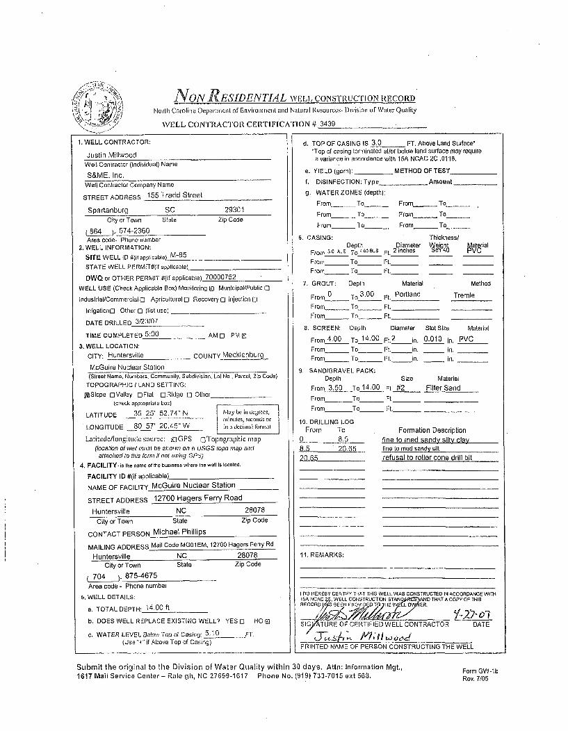
61,
N ON RESIDENTIAL wl,, CONSTRUCT! ON RECORDi
North Carolina Departmeni t of' Erironmetroll and NalLtra I Resources- Division url \ater Quality
WELL CONTRACTOR CERTIFICATION # 3439
1. WELL CONTRACTOR:
Justin Millwood
Well Contractor (Individual) Name
S&ME, Inc.
Well Contractor Company Narne
STREET ADDRESS 155 Tradd Street
Spartanburg SC 29301
City or Town State Zip Code
B64 ). 574-2360Area code- Phone number
2. WELL INFORMATION:
SITE WELL ID #(if applicable) M-85
STATE WELL PERMITI/(if applicable)
DWQ or OTHER PERMIT #(if applicable) 70000752
WELL USE (Check Applicable Box) Monitoring g) Municipal/Public 1-
Industrial/Commercial 0 Agricultural 0 Recovery 0 Injection 0
Irrigation[3 Other 0 (list use)
DATE DRILLED 3123/07
TIME COMPLETED 5:00 AM CI PME
3, WELL LOCATION:
CITY: Huntersville COUNTY Mecklenburg
McGuire Nuclear Station(Street Name, Numbets, ComMnLrity. Subdivision, Lot No,. Parcel. Zip Code)
TOPOGRAPHIC f LAND SETTING:
p.iSlope OValley oFlat CRidge 1l Other
(check appropriate box)
LATITUDE 35 25' 52.74" N May be in degrees,mninteis, seconrds or
LONGITUDE 80 57' 20.45" W ira decinatl IbrnItar
Latitudc/longi tulde sOurcc: iUGPS o'Topographic map
(location of welt must be slhowrr on a USGS lopo map andattachred to Iffis fornr if not usirg GPS)
4. FACILITY- is the name of the business where the well is located.
FACILITY ID #(if applicable)
NAME OF FACILITY McGuire Nuclear Station
STREET ADDRESS 12700 Hagers Ferry Road
Huntersville NC 28078
City or Town State Zip Code
CONTACT PERSON Michael Phillips
MAILING ADDRESS Mail Code MG01EM, 12700 Hagers Ferry Rd
Huntersville NC 28078City or Town State Zip Code
704 ) 875-4675Area code - Phone number
5. WELL DETAILS:
a. TOTAL DEPTH: 14.00 ft
b. DOES WELL REPLACE EXISTING WELL? YES LI NO E
c, WATER LEVEL Below Top of Casing: 5.-10 FT.(Use "+" if Above Top of Casing)
d. TOP OF CASING IS 3.0 FT. Above Land Surface*'Top of casing terminated al/or below land surface may requirea variance in accordance with 15A NCAC 2C .0118.
e. YIELD (gpm): _ METHOD OF TEST
f. DISINFECTION: Type Amount
g. WATER ZONES (depth):
From_ To_ From_ To
From- To_ From_ To
From_ To_ From - To
6. CASING: Thickness/Depth Diameter \ýeighý •/trial
Froi 3.0 ALS To 4.00 BLS Ft. 2 inches ch4
From_ To_ Ft._
From To_ Ft._
7. GROUT: Depth Material Method
From 0 To 3.00 Ft. Portland Tremle
From To_ Ft.
From To _Ft.
8. SCREEN: Depth Diameter Slot Size Material
From 4.00 To 14.00 Ft.2 in. 0.010 in. PVC
From To Ft. in. in.
From To Ft. in. in,
9. SANDIGRAVEL PACK:Depth Size Material
From 3.50 To 14.00 Fl, #2 Filter Sand
Frorn To_ Ft.
From To Ft._
10. DRILLING LOGFrom To Formation Description
0 8.5 fine to med sandy sillty clay
8.5 20.65 line to med sandy silt20.65 refusal to roller cone drill bit
11. REMARKS:
too HERESY CERTItY THAT TrllS WELL WAS CONSTRUCTED IN ACCORDANCE WITH15A NCAC 2,q. WELL CONSTRUCTION STANO RO5"AND THAT A COPY OF THIS
RECORD 4S EE THEW , ER.
SIGATURE OF CERTIFIED WELL CONTRACTOR DATE
PRINTED NAME OF PERSON CONSTRUCTING THE WELL
Submit the original to the Division of Water Quality within 30 days. Attn: Information Mgt.,1617 Mail Service Center - Raleigh, NC 27699-1617 Phone No. (9191 733-7015 ext 568.
Form GW-lbRev. 7/05

C, ,,. . . .;.
N ONR.?ESIDENTIAL N.V:LL CONSTRUCTION RECORD
North Carolina Deptart'int ol Environnent and Natural Resources- Division of Water Quality
WELL CONTRACTOR CERTIFICATION # 2717
1. WELL CONTRACTOR:
Jay Little
Well Contractor (individual) Name
S&ME, Inc.
Well Contractor Company Name
STREET ADDRESS 9751 Southern Pine Boulevard
Charlotte NC 28273
City or Town State Zip Code
(704 ). 523-4726
Area code- Phone number2. WELL INFORMATION:
SITE WELL ID t(it applicable)_ M-103
STATE WELL PERMITI(iI applicable)_
DWQ or OTHER PERMIT #(if applicable) 70000752
WELL USE (Clheck Applicable Box) Monitoring Ej Municipal/Public 0
IndustrialiComrnercial E0 Agricultural 0 Recovery 0 Injection Cn
IrrigationO] Other Cl (list use)
DATE DRILLED 4/4/07
TIME COMPLETED 5:00 AM Fl PM P9
3. WELL LOCATION:
CITY: Hluntersville COUNTY Mecklenburg
McGuire Nuclear Station(Street Name, Numbers, Comrunily, Subdivision, Lot No., Parcel. Zip Code)
TOPOGRAPHIC I LAND SETTING:
EISIope C]Vallcy -Filat uRidge 0 Other(check appropiale bel:)
LATITUDE 35 25' 48.29" N Mly be in degrecs,Inlilttale, seconds or
LONGITUDE 80 57' 14.67" W ina rlecim,;I fornat
Latituce/longiitLdo soutrcc: iOGPS oTopographic nap
(localion of woll mnust be shown On a USGS lopeo map and
attached to Ihis foln if nol usirt GPS)
4. FACILITY- is the name of the business where the well is located.
FACILITY ID #(if applicable)
NAME OF FACILITY McGuire Nuclear Station
STREET ADDRESS 12700 Hagers Ferry Road
Huntersville NC 28078
City or Town State Zip Code
CONTACT PERSON Michael Phillips
MAILING ADDRESS Mail Code MG01 EM, 12700 Hagers Ferry Rd
Huntersvilte NC 28078
City or Town State Zip Code
704 ) 875-4675Area code - Phone number
5. WELL DETAILS:
a. TOTAL DEPTH: 22.00 ft
b. DOES WELL REPLACE EXISTING WELL? YES - NO p
c. WATER LEVEL Belon Top of Casing: 12.00 FT.(Use '+" if Above Top of Casing)
d. TOP OF CASING IS 3.0 FT. Above Land Surface**Top of casing terminated at/or below land surface may require
a variance in accordance with 15A NCAC 2C .0118,
e. YIELD (gpin): METHOD OF TEST
f, DISINFECTION: Type _Amount
g. WATER ZONES (deplh)"
From- To_ From_ To
From- To_ From_ To
Fromn- To-- From_ _ To
6. CASING: Thickness/Depth Diameter Fteihgh (ral
From 3.0 ALS To a 00BLs Ft. 2 inches
From- To-To Ft._ _
From To_ Ft.__
7. GROUT: Depth Material Method
From 0 To 4.50 Ft. Portland Tremie
From_ _ To_ Ft.
From _ To_ Ft.
8. SCREEN: Depth Diameter Slot Size Material
From 7.00 To 22.00 Ft.2
in. 0.010 in. PVC
From - To__ Ft. in. _ in.
From _ To Ft. in. in.
9. SAND/GRAVEL PACK:Depth Size Material
From 6.00 To 22.00 Ft. #1 Filter Sand
From To_ Ft._
Frorn To_ Ft.
10, DRILLING LOGFrom To Formation Description
0 7.5 fine sandy clayey silt and fine to medsandy silly clay - saprolite
7.5 -22 silty fine to med sand - saprolite andweathered rock
11. REMARKS:
1 00 HEREBY CERTIFY THAT THIS WELL WAS CONSTRUCTED IN ACCORDANCE WITHISA iCAC 2C, WELL CONSTRUCTION STANDARDS, AND THATA COPY OF THISRECORDO au IEEN PROVIDED TO Frpa WE L OWNER.
,91"GNA-RE OF CERTIFIED WELL CONTRACTOR//X< DATE
PRINTED NAIl- OF PERSON CONSTRUCTING THE WELL
Submit the original to the Division of Water Quality within 30 days. Attn: Information Mgt.,1617 Mail Servico Center - Raleigh, NC 27699-1617 Phone No, (919) 733-7015 ext 5G8.
Form GW-lbRev. 7/05

'.IAII
/ ION •RESIDENTIAL WELL CONSTRUC'TION RECORD
North Crmolina DepartmentI of Einvirunnment and Natiral Resources- D ivision of W"ater Quality
WELL CONTRikACTOR CEWTIFICATION ,5 2717
1. WELL CONTRACTOR:
Jay Little
Well Contractor (Individual) Name
S&ME, Inc.Well Contractor Company Name
STREET ADDRESS 9751 Southern Pine Boulevard
Charlotte NC 28273
City or Town State Zip Code
(704 ). 523-4726Area code- Phone nLimber
2. WELL INFORMATION:
SITE WCELL ID #(if applicbte) M-1 03R
STATE WELL PERMIT#0if applicable)
DWQ or OTHER PERMIT #(if applicable) 70000752
WELL USE (Check Applicable Box) Monitoring M Mlunicipal/Public -
Industrial/Commercial C Agricultural D] Recovery o Injection o
Irrigation[3 Other 0 (list use)
DATE DRILLED 3/29/07
TIME COMPLETED 5:00 AMO PMIE]
3. WELL LOCATION:
CITY: Huntersvitle COUNTY Mecklenburg
McGuire Nuclear Station(Street Name. tJrumilrs. Commsnity, Subdivision, 1.0o No., Parcel, Zip Code)
TOPOGRAPHIC / LAND SETTING:
I3Slope I'3Val/ey _Flal rfiRidge C0 Other(chack appropriale box)
LATITUDE 35 25' 48.33" N May be in) regrees,Inll• IS, SacOntt't o'
LONGITUDE 30 57' 14.39"W inn deciml li•no'at
Latitude/longi ItIde source; Q OPS o Topographic map
(iocation of well must be shown on a USGS topeo map andattached to this form if not using GPS)
4. FACILITY- is the name of the business where the well is located.
FACILITY ID #(if applicable)
NAME OF FACILITY McGuire Nuclear Station
STREET ADDRESS 12700 Hagers Ferry Road
Huntersville NC 28078
City or Town State Zip Code
CONTACT PERSON Michael Phillips
MAILING ADDRESS Mail Code MG01 EM, 12700 Hagers Ferry Rd
Huntersville NC 28078
City or Town State Zip Code
)04 ) 875-4675
Area code - Phone number
5. WELL DETAILS:
a. TOTAL DEPTH: 37.00 ft
b. DOES WELL REPLACE EXISTING WELL? YES El NOU
c. WATER LEVEL Below Top of Casing: 11.06 FT.(Use "+" if Above Top of Casing)
cf. TOP OF CASING IS 3.0 FT. Above Land Surface**Top of casing terminated at/or below land surface may require
a variance in accordance with 15A NCAC 2C .0118.
s. YIELD(gpm): M'ETHOD OF TEST
f. DISINFECTION: Type_ _ Amount -
g. WATER ZONES (depth):
From - To_ From_ To
From - To - From To
From_ To - From _ To_
6. CASING: Thickness/Depth Diameter Weight MVltrlat
From 3.0 ALS To 26.)00L5 Ft. 2 inches ch 4
From - To Ft._
From To - Ft._
7. GROUT: Depth Material Method
From 0 To 22.20 Ft. Portland Tremie
From To Ft.
From To Ft.
8. SCREEN: Depth Diameter Slot Size Material
From 26.00 To 36.00 Ft.2 in. 0.010 in. PVC
From_ _ To Ft. in. - in.
From_ To Ft. in, in.
9. SANDIGRAVEL PACK:Depth Size Material
I-rom 24.70 To 37.00 Ft. #2 Filter Sand
From To_ Ft.
From -To_ _ Ft._
10. DRILLING LOGFrom To Formation Description
0 7.5 fine sandy clavev slit and fine to med
7.5 247
24.724.7 45
11, REMARKS:
sandy silty clay - salrolltesilty fine to med sand - sadrolite andweathered rockrefusal to roller cone drill bit
weathered rock and sound rock -fine ctrained oranite
I00 HEREBY CERTIFY THAT "tIS WELL WAS CONSTRUCTED IN ACCORDANCE WITH15A HICAC 2C. WELL CO'STRUCTION STANDARDS, AND THATA COPY OF THISRECORoyA. BEEN PROVIDEO T10 112 WELL OWNER,
RE OF CERTIFIED WELL CONTRACTOR DATE
--Y- .7K.- f" i/PRINTED NA•ME OF PERSON CONSTRUCTING THE WELL
Submit the original to the Division of Water Quality within 30 days. Attn: Information Mgt.,1617 Mail Service Center - Raleigh, NC 27699-1617 Phone No. (919) 733-7015 ext 568. Form GW-lb
Rev. 7105

I?
(~~\o
ON RNRESIDENTIAL WE.,LL CONSTRUCTION RECORD
North Carolina Deparmeint of E'nvironnment and Naturarl Resolurces- Division of W\Vtcr Quality
WELL CONTRACTOR CERTIFICATION # 3439
1. WELL CONTRACTOR:
Justin MillwoodWell Contractor (Individual) Name
S&ME, Inc.
Well Contractor Company Name
STREET ADDRESS 155 Tradd Street
Spartanburg SC 29301
City Or Town State Zip Code
(864 ). 574-2360Area code- Phone number
2. WELL INFORMATION:
SITE WELL ID fl(if applicable) M-104R
STATE WELL PERMIT'flit applicable)__
DWQ or OTHER PERMIT #(if applicable) 70000752
WELL USE (Check Applicable Box) Monitoring n fvlunicipalPuLblic El
Industrial/Cornmecial 0 Agricultural 0 Recovery 0 Injection 13
Irrigationo Other 03 (list use)
DATE DRILLED 3/26/07
TIME COMPLETED 5:00 AM 1] PM sI
3. WELL LOCATION:
CITY: Huntersville COUNTY Mecklenburg
McGuire NMrr:Iear Station
d, TOP OF CASING IS 3.0 FT. Above Land Surface*'Top of casing terminated at/or below land surface may require
a variance in accordance with 15A NCAC 2C .0118.
a. YIELD (gpm): ..... . METHOD OF TEST
I. DISINFECTION: Type Amount
g. WATER ZONES (depth).
Frome _ TTo From_ To
From - To_ _ From_ To
From_ ______To_ From _ To
6. CASING: Thickness/Depth Diameter Weight Material
From 0 ALS To .-r• aLS 4 Inches Sch 40 PV,
From 3.0 ALS To 42.00 Ft. 2 inches Sch 40 PVC
From_ To Ft._
7. GROUT: Depth Material Method
From 0 To 39.80 Ft. Portland Trenie
From To Ft.
From To - Ft.
8. SCREEN: Depth Diameter Slot Size Material
From 42.00 To 47.00 Ft.2
in. 0.010 in. PVC
From---- To_ _ Ft. in. i In. __
From _ To _ Ft. in. in,
9. SAND/GRAVEL PACK:Depth Size Material
From 41.00 To 47.00 Ft. 42 Filter Sand
From To_ Ft.
From To - Ft._
10. DRILLING LOGFrom To Formation Description
0 8 fine to med sandy silty clay
8 39.8 silty fine to med/coarse sand39.8 refusal to roller cone drill bit
39,8 60.04 weathered and sound rock -coarse grained granite
11. REMARKS:
(Street Name. tINlDrbers, Community, Subdivision. Lot No., Parcel, Zip Crde)TOPOGRAPHIC / LAND SETTING:
C]Slope fiValley r-Flat Ia. Ridge 0 Olher
(check appropriate box)
LATITUDE 35 25' 51.86" N May be in degrees,IrlillUteC , seconds or
LONGITUDE 80 57' 16.20" W ilal decimal tonIrat
Latittrde/longiuLade source: > GPS oTopographic map
(location of well/ rust be s/otn on a USGS topo map ardattached to this forin if not using GPS)
4. FACILITY- is the name of the business where the well is located,
FACILITY ID #(if applicable)
NAME OF FACILITY McGuire Nuclear Station
STREET ADDRESS 12700 Hagers Ferry Road
Huntersville NC 28078
City or Town State Zip Code
CONTACT PERSON Michael Phillips
MAILING ADDRESS Mail Code MG01EM, 12700 Hagers Ferry Rd
Huntersville NC 28078City or Town State Zip Code
704 )- 875-4675
Area code - Phone number5. WELL DETAILS:
a. TOTAL DEPTH: 47.00 ft
b. DOES WELL REPLACE EXISTING WELL? YES o NOD l
c. WATER LEVEL Below Top of Casing: 37.40 FT.(l--e ", " if Above Top of Casing)
I DO HERE12y CERTIFY THAT THIS WELL WAS CONSTRUCTED IN ACCORDANCE WITH15A rlCAC 2C, WELL CONSTRUCTION STANPA•DS. AND THAT A COPY OF THIS
RECQ0 HAS BEEN PROVI1DOET THE WNER,
,fIGNATURE OF CERTIFIED WELL CONTRACTOR DATE
PRINTED NAME OF PERSON CONSTRUCTING THE WELL
Submit the original to the Division of Water Quality within 30 days. Attn: Information Mgt,,1617 Mail Service Center- Raleigh, NC 27699-1617 Phone No. (919) 733-7015 ext 568.
Form GW-lbRev. 7105

May 7, 2007
North Carolina Department of Environment and Natural ResourcesDivision of Water Quality1617 Mail Service CenterRaleigh, North Carolina 27699-1617
ATTN: Information Management
Reference: NON-RESIDENTIAL WELL CONSTRUCTION RECORDS - SUBMITTAL #1McGUIRE NUCLEAR STATION12700 Hagers Ferry RoadHuntersville, North CarolinaS&ME Project No. 1264-06-724
Ladies and Gentlemen:
On behalf of Duke Energy, S&ME, Inc. (S&ME) is submitting the enclosed completed and signed Non-Residential Well Construction Records for the following seven (7) groundwater monitoring wellsinstalled at the McGuire Nuclear Station (MNS) site:
• M-82 • M-103* M-84 • M-103R• M-84R ° M-104R.° M-85
Duke Energy is voluntarily installing groundwater monitoring wells at MNS as part of a site-widehydrogeologic evaluation. S&ME will submit these Non-Residential Well Construction Records on aperiodic basis as well installations are completed, this being the first submittal (i.e., Submittal #1).
On behalf of Duke Energy, S&ME thanks you for your receipt of these records. Should you have anyquestions or need additional information, please contact us.
Sincerely,S&ME, Inc.
&cott E. Dacus, P.G. E.Project Geologist (S or Engineer/Project Director
enclosures
cc: Messrs. Steve LeRoy, Ed Sullivan, Tim Hunsucker; Duke Energy
SAENVIRO Sr2006\264 ProjecrSA.6406724 McGuire Nuclear Gva undwaserSrud9C•• DENR Well RecordvcdWenr well records submittel doc
S&ME, INC. / 155 Tradd Street / Spartanburg, SC 29301 / p 864.574.2360 f 864.576.8730
1 Marcus Drive, Suite 301 / Greenville, SC 29615 / p 864-232-8987 / www.srneinc.com

.NON RESIDENTIAL wrELL, CONSTRU1CT.ION RECORDNorth Carolina Department of Environment and Natural Rcsources- Division of Water Quality
WELL CONTRACTOR CERTIFICATION tt 3439
1. WELL CONTRACTOR:
Justin Millwood
Well Contractor (Individual) Name
S&ME, Inc.
Well Contractor Company Name
STREET ADDRESS 155 Tradd Street
Spartanburg SC 29301
City or Town State Zip Code
(864 ). 574-2360Area code- Phone number
2. WELL INFORMATION:
SITE WELL ID #(if applicable) M-82
STATE WELL PERMITAfif applicable) _
DWQ or OTHER PERMIT #(if applicable) 70000752
WELL USE (Check Applicable Box) Moniloring Z) Municipal/Public 0
IndustriallCommercial 0 Agricultural 0" Recovery 0 Injection rJ
trrigationFl Other [J (list use)
DATE DRILLED 3/21/07
TIME COMPLETED 5:00 AM [] PM 5j3. WELL LOCATION:
CITY: Huntersville COUNTY Mecklenburg
McGuire Nuclear Station(Street Name, Numbers, Community, Subdivision, Lot No., Parcel, Zip Code)
TOPOGRAPHIC / LAND SETTING:SISlope OValley oFlat ORidge 0 Other
(check appropriate box)
LATITUDE 35 25' 47.66" N Mlay bc il dcgicer:,ntillules, secotnds or
LONGITUDE 80 57' 17.35" W inan declinal rrlwiut
Latitude/Ioniitucde sourceC: oGPS oTopographic 1al)(location of well mnttsl be shown on a USGS topo n•ap andattached to thits form i111ot using GPS)
4. FACILITY- is the name of the business where the well is located.
FACILITY ID #(if applicable)
NAME OF FACILITY McGuire Nuclear Station
STREET ADDRESS 12700 Hagers Ferry Road
Huntersville NC 28078City or Town State Zip Code
CONTACT PERSON Michael Phillips
MAILING ADDRESS Mail Code MG01EM, 12700 Hagers Ferry Rd
Huntersville NC 28078City or Town State Zip Code
704 )- 875-4675
Area code - Phone numberS. WELL DETAILS:
a. TOTAL DEPTH: 34.60 ft
b. DOES WELL REPLACE EXISTING WELL? YES 0 NO [9
c. WATER LEVEL Below Top of Casing: 25.37 FT.(Use "+" if Above Top of Casing)
d. TOP OF CASING IS 3.0 FT. Above Land Surface''Top of casing terminated al/or below land surface may requirea variance in accordance with 15A NCAC 2C .0118.
a. YIELD (gptn): . METHOD OF TEST
L. DISINFECTION: Type Amount
g. WATER ZONES (depth):
From_ To_ From_ To
From To_ From_ To
From_ To_ From_ To
6. CASING: Thickness/Depth Diameter Weigh flrial
From 3.0 ALS To 2.1.611 BLS Ft. 2 inches ch4
From To_ _ Ft._
From To Ft.- -
7. GROUT: Depth Material Method
From 0 To 19.80 Ft Portland Tremie
From To Ft.
From_____ To - Ft.
8. SCREEN: Depth Diameter Slot Size Material
From 24.60 To 34.60 Ft.2
in. 0.010 in. PVCFrom To_ _ F_.- in. In.From To_____ _ Ft. In. In.
9. SAND/GRAVEL PACK:Depth Size Material
From 22.05 To 34.60 Ft. #1 Filter Sand
From 0 FL-To_ Ft.From To______ Ft. -
10, DRILLING LOGFrom To Formation Description
0 9
9 34.6
11. REMARKS:
fine sandy silt
mlcaceous, silty sand and sandy silt
refusal to roller cone drill bit
I DO HEREBY CERTIFY THAT THIS WELL WAS CONSTRUCTEO IN ACCORDANCE WITH15A NCAC 2C. WELL CONSTRUCTION STANDAROS. AND THAT A COPY OF THISRECORD HIAS BEEN PROVIDED TO THE OWNER..
SlGXA'[JURE.OF CERTIFIED WELL CONTRACTOR DATE
PRINTED NAME OF PERSON CONSTRUCTING THE WELL
Submit the original to the Division of Water Quality within 30 days. Attn: Information Mrgt.,1617 Mall Service Center - Raleigh, NC 27699-1617 Phone No. (919) 733-7015 ext 568.
Form GW-lIbRev. 7/05

rtAIf
"ii I..~~~~- -~9
No, Af R ELSIDIEN TLIL W,ýll..LC'ONS'1IRIJC(TIONIRECORDNoril Ce.'rlina Departrment of Envh'irnorinlw nod Natural Recsources- I) vision of Water Quality
WELL CO(.NTRIbkCI'OR CE"RTIFICATION # 2717
1, WELL CONTRACTOR:
Jay LittleWell Contractor (Individual) Name
S&ME, Inc.Well Contractor Company Name
STREET ADDRESS 9751 Southern Pine Boulevard
Charlotte NC 28273City or Town State Zip Code
704 )- 523-4726Area code- Phone number
2. WELL INFORMATION:
SITE WELL ID f/(if applicable) M-84
STATE WELL PERMITf(if applicable)_
DWQ or OTHER PERMIT f/(if applicable) 70000752
WELL USE (Check Applicable Box) Moniloring 9) Municipal/Public 1-
Industrial/Commercial D Agricultural C- Recovery 0 Injection D
Irrigationo Other I] (list use)
DATE DRILLED 3/28/07
TIME COMPLETED 5:00 AMD PMrJ
3. WELL LOCATION:
CITY: Huntersville COUNTY Mecklenburg
McGuire Nuclear Station
d. TOP OF CASING IS 3.0 FT. Above Land Surface**Top of casing lerminated at/or below land surface may require
a variance in accordance with 15A NCAC 2C .0118.
o, YIELD (gpm): ._ ._ METHOD OF TEST
f. DISINFECTION: Type Amount
g. WATER ZONES (depth):
From_ To - From_ To
From- To_ From - To
From To__ From_ To
6, CASING: ThicknesslDepth Diameter VWeight 4 aeiat
From 3.0 ALs To S.0O3 S Ft. 2 inches ch 4
Fron t To Ft.From_ _ To_ Ft._
7. GROUT: Depth Material Method
Frorn 0 To 3.00 Ft. Portland Tremie
From To Ft.From To- Ft.
8. SCREEN: Depth Diameter Slot Size Material
From 5.00 To 15.00 Ft2 in. 0.010 in. PVCFrom To_ Ft. in. in.From To_ Ft. in. in.
9. SAND/GRAVEL PACK:Depth Size Material
From 4.00 To 15,00 Ft. #1 Filter Sand
Fromn To Ft._ _
From_ _ To _ Ft.
10. DRILLING LOGFrom To Formation Description
0 9 fine to med sandy silty clay
9 15 fine to med sandy clayey slit andsilty sand
11. REMARKS:
(Street Name, NiUmbers, Community. Subdivision, L.el No., Parcel, Zip Code)TOPOGRAPHIC I LAND SETTING:IdSlope nValley EFlan ORidge 0 Other
(chock appropriate box)
LATITUDE 35 25' 49.55" N May be in degrees,-n etelen, seconds or
LONGITUDE 80 57' 19.67" W in a decimal I'rm n
Latitude/longiiudc soiurce: 100PS M IopogrAlhic nll)(location of nel/ musl be shown on a USGS 1ope rMap andattached to I/tis form if not using GPS)
4. FACILITY- is the nare of the business where the well is located.
FACILITY ID #(if applicable)_
NAME OF FACILITY McGuire Nuclear Station
STREET ADDRESS 12700 Hagers Ferry Road
Huntersville NC 28078
City or Town State Zip Code
CONTACT PERSON Michael Phillips
MAILING ADDRESS Mail Code MG01EM, 12700 Hagers Ferry Rd
Huntersville NC 28078City or Town State Zip Code
704 ). 875-4675
Area code - Phone number
5. WELL DETAILS:
a. TOTAL DEPTH: 15.00 [t
b, DOES WELL REPLACE EXISTING WELL? YES 0 NO 0
c. WATER LEVEL Below Top of Casing: 7.60 FT.(Use "+" if Above Top of Casing)
IDO HEREBY CERTIFY THAT THIS WELL WAS CONSTRUCTED IN ACCORDANCE WITH15A NCAC 2C. WELL CONSTRUCTION STANDARDS, AND THAT A COPY OF THISRECOFP-HA,,S bEENROIDED TO TIE WL0.,ONER.
*4SIGN• RE OF CERTIFIED WELL CONTRACTORzM+, . Z"/; DATE
PRINTED NAUE 01 PERSON CONSTRUCTING THE WELL
Submit the original to the Division of Water Quality within 30 days. Attn: Information Mgt.,1617 Mail Service Center- Raleigh, NC 27699-1617 Phone No. (919) 733-7015 ext 56B. Form GW-lb
Rev. 7/05

/ rt-~-l A~) AEON RL ESED ENTIAL WVELL CONSTrRucrION R.ECORD
North Carolina Department of Environ'ment and Natural Resources- ivision of Water Quality
WELL CONTRIZACTOR CERTIFICATION it 2717
1, WELL CONTRACTOR:
Jay LittleWell Contractor (Individual) Name
S&ME, Inc.
Well Contractor Company Name
STREET ADDRESS 9751 Southern Pine Boulevard
Charlotte NC 28273
City or Town State Zip Code
704 )_ 523-4726Area code- Phone number
2. WELL INFORMATION:
SITE WELL ID #(if applicable) M-84R
STATE WELL PERMIT#(If applicable).
DWQ or OTHER PERMIT 4(if applicable).70000752
WELL USE (Check Applicable Box) Monitoring 91 Municipal/Public Q
Ifidustrial/Commercial [] Agricultural E] Recovery [] Injection I]
IrrigationO Other I (list use)
DATE DRILLED 3/22/07
TIME COMPLETED 5:00 AM 0 PM Lt
3. WELL LOCATION:
CITY: Huntersville COUNTY Mecilsenburg
McGuire Nuclear Station
d. TOP OF CASING IS 3.0 FT, Above Land Surface*'Top of casing lerminated at/or below land surface may require
a variance in accordance with 15A NCAC 2C .0118.
a. YIELD (gpm): METHOD OF TEST
f. DISINFECTION: TypeAmount
g. WATER ZONES (depth):
From_ _ To_ From To
From- To_ From_ To
From_ _ To_ From_ To
6. CASING: Thickness/Depth Diameter eht aterial
From 1.0 ALs To so2.00as Ft. 2 inches ch4
F rom _ _ o 1 Ft. -
From To_ Ft.
7. GROUT: DeptIh Material Method
Froin 0 To 15,00 Ft. Portland Tremie
From - To_ Ft.
From_ To_ Ft.
8. SCREEN: Depth Diameter Slot Size Material
From 20.00 To 25.00 Ft.2
In. 0,010 in. PVCFrom_ To - Ft. in. in.From - To_ _ t. in. _ in.
9. SAND/GRAVEL PACK:Deplh Size Material
From 18.70 To 28.50 Ft. #2 Filter Sand
From To_ Ft.
From To_ _ Ft._
(Street Name, Numbers, Community, Subdivision, Lot No., Parcel, Zip Code)
TOPOGRAPHIC / LAND SETTING:
Slope LOValley oFlat ORidge 0 Other
(check sppropriale box)
LATITUDE 35 25' 49.60" N May be in degrees,rllhinlnle, seconIds or
LONGITUDE 80 57' 19.64" W in a decirnal INsrerar
Latitude/longilture source: sDGPS 0'Topographic map(location of well oust be Slhown on a USGS ropo map and
attached to this form fif ct using GPS)
4. FACILITY- is the name of the business where the well is located.
FACILITY ID #(if applicable)
NAME OF FACILITY McGuire Nuclear Station
STREET ADDRESS 12700 Hagers Ferry Road
Huntersville NC 28078
City or Town State Zip Code
CONTACT PERSON Michael Phillips
MAILING ADDRESS Mail Code MG01 EM, 12700 Hagers Ferry Rd
Huntersville NC 28078City or Town State Zip Code
(,704 ) 875-4675Area code - Phone number
5. WELL DETAILS:
a. TOTAL DEPTH: 28.50 ft
b. DOES WELL REPLACE EXISTING WELL? YES L NO 1
c. WATER LEVEL Below Top of Casing: 20.34 FT.(Use "+" if Above Top of Casing)
10. DRILLING LOGFrom To
0 9
9 15
15 18.7
18.7
18 7 28R5
11. REMARKS:
Formation Descriptionfine to med sandy slltysclayFine to med sandy clayey silt andsilty sandsiltv fine to coarse sand w/ rockfragments - saprollte
refusal to roller cone drill bit
sound rock - granite
I DO IIEREY CERTIFY TI(AT THIS WELL WAS CONSTRUCTED IN ACCORDANCE WITH15A 4CAC 2C. WELL COI-ISTRUCTION STANDARDS, AND THATA COPY OF THISRECORD HAýPDEEN PROVIDED TO THE WELL OWNER.
ý5'IG1NAgt•E OF CERTIFIED W ELL CONTRACTOR
- 1 -3; i'V
DATE
PRINTED N4ME OF PERSON CONSTRUCTING THE WELL
Submit the original to the Division of Water Quality within 30 clays. Attn: Information Mgt,,1617 Mail Service Center- Raleigh, NC 27699-1617 Phone No. (919) 733-7015 ext 568.
Form GW-1 bRev. 7/05

,;-rf.
~~~*,.~
NON.RESIDENTIAL vvWF, CONSTRUCTr ON RECORD
North Carolin a Departmcnt o" tEiiviroinmrrent and Ntural I Resourcus- Division or \Vater Quality
WELL CON'rRACTOIR. CERTIFICATION fl 3439
1. WELL CONTRACTOR:
Justin Millwood
Well Contractor (Individual) Name
S&ME, Inc.Well Contractor Company Name
STREET ADDRESS 155 Tradd Street
Spartanburg SC 29301
City or Town State Zip Code
(864 )- 574-2360Area code- Phone number
2. WELL INFORMATION:
SITE WELL ID Ofit applicable) M-135
STATE WELL PERMITfl(if applicable)
DWQ or OTHER PERMIT #(if applicable) 70000752
WELL USE (Check Applicable Box) Monitoring M Municipal/Public 0
Industrial/Commercial (J Agricultural C Recovery 0 Injection c
IrrigationC] Other [I (list use)
DATE DRILLED 3/23/07
TIME COMPLETED 5:00 AMO0 PMEi
3. WELL LOCATION:
CITY: Huntersville COUNTY Mecklenburg
McGuire Nuclear Station(Street Name, Numbers, Community, Subdivision, Lot No,, Parcel, Zip Code)
TOPOGRAPHIC / LAND SETTING:
pOSlope ciValley OFlat oRidge CI Other(check appropriate box)
LATITUDE 35 25' 52.74' N May be in degrees,minultes, ecornds or
LONGITUDE 80 57' 20.45" W ir a dlecimal Forrmal
Latitudc/tlogi trc losoutce: xoGPS oTopographic map(location of well nrust be shown on a USGS tope map arid
attached to tirs forir if not using GPS)
4. FACILITY- is the name of the business where the well is located.
FACILITY ID #(if applicable)
NAME OF FACILITY McGuire Nuclear Station
STREET ADDRESS 12700 Hagers Ferry Road
Huntersville NC 28078
City or Town State Zip Code
CONTACT PERSON Michael Phillips
MAILING ADDRESS Mail Code MG01EM, 12700 Hagers Ferry Rd
Huntersvilie NC 28078
City or Town State Zip Code
704 . ) 875-4675
Area code - Phone number
5. WELL DETAILS:
a. TOTAL DEPTH,: 14.00 ft
b. DOES WELL REPLACE EXISTING WELL? YES 0- NO E,
c. WATER LEVEL Below Top of Casing: 5.10 FT.(Use '+" if Above Top of Casing)
d. TOP OF CASING IS 3.0 FT, Above Land Surface*'Top of casing terminated al/or below land surface may require
a variance in accordance with 15A NCAC 2C .0118.
a. YIELD (gpm): METHOD OF TEST
f. DISINFECTION: Type_ Amount
g. WATER ZONES (depth):
From - To From_ To
From- To_ From_ To
From To_ _ From_ To_
6. CASING: Thickness/Depth Diameter egVh, Mriat
From 3o ALS To 4.00 8ls Ft, 2inches 4
From _ To _ Ft._From_ To_ Ft._
7. GROUT: Depth Material MethodFrom 0 1To 3.00 Ft. Portland Tremie
From To - Ft.
From__ To_ Ft.
8, SCREEN: Depth Diameter Slot Size Material
From 4.00 To 14.00 Ft.2
in. 0,010 in. PVC
From _ To - Ft- in. _ in.
From To Ft. in. -in.
9. SAND/GRAVEL PACK:Depth Size Material
From 3.50 To 14.00 Ft. #2 Filter Sand
From To Ft._
From To Ft._
10. DRILLING LOGFrom To Formation Description
0 8.5 fine to med sandy silty clay
8.5 20.65 fine to med sandy sill
2 _0._6 __5 refusal to roller cone drill bit
11. REMARKS:
I DO HEREBY CERTIFY THAT THIS WELL WAS CONSTRUCTED IN ACCORDANCE WITHrANOAC L ONmSTRuCTIOrI SrANo RM'ANO THAT ACOPY OF THIS
SIG tATURE OF CERTIFIED WELL CONTRACTOR DATE
PRINTED NAME OF PERSON CONSTRUCTING THE WELL
Submit the original to the Division of Water Quality within 30 days. Attn: Information Mgt.,1617 Mail Service Center- Raleigh, NC 27699-1617 Phone No. (919) 733-7015 ext 568. Form GW-lb
Rev. 7105

NON R. ESWENTIAL WELL CONSTIRUCT1ON RECORD
North Catoin i Departlment of Environllent and Natural Resources- Division of\ Water Quality
WELL CONTRACTOIt CERTIFICATION # 2717
1. WELL CONTRACTOR:
Jay LittleWell Contractor (Individual) Name
S&ME, Inc.
Well Contractor Company Name
STREET ADDRESS 9751 Southern Pine Boulevard
Charlotte NC 28273City or Town State Zip Code
(704 ). 523-4726Area code- Phone number
2. WELL INFORMATION:
SITE WELL ID #(if applicable) M-1 03
STATE WEtLL PERMIT//(it applicable)_ .
DWQ or OTHER PERMIT #(if applicable) 70000752
WELL USE (Check Applicable Box) Monitoring r..j MUnicipal/Public 0
Industrial/Commercial Cn Agricultural C Recovery l- Injection F
Irrigationo Other Cl (list use)
DATE DRILLED 414/07
TIME COMPLETED 5:00 AMfl PM [X]
3. WELL LOCATION:
CITY: HIuntersville COUNTY Mecklenburg
McGuire Nuclear Station
(Street Name. Numbers, Community, Subdivision. Lot No.. Parcel, Zip Code)TOPOGRAPHIC /LAND SETTING:
0rSIop OValley OFlat .jRidge 0 Other
(check appropriile box)
LATITUDE 35 25' 48.29" N IMay be in rlagrecs.- himltes, seconads or
LONGITUDE 80 57' 14.67" W in a decilal borinal
Latitude/lonoitude source: ji GPS ElTopographic map
(location of ve/l l must be shown on a USGS topo nmap andatlached to this farm if not usintg GPSJ
4. FACILITY- is the name of the business where the well is located.
FACILITY ID #(if applicable)
NAME OF FACILITY McGuire Nuclear Station
STREET ADDRESS 12700 Hagers Ferry Road
Huntersville NC 28078
City or Town State Zip Code
CONTACT PERSON Michael Phillips
MAILING ADDRESS Mail Code MG01EM, 12700 Hagers Ferry Rd
Huntersville NC 28078
d. TOP OF CASING IS 3.0 FT. Above Land Surface'*Top of casing terminated at/or below land surface may requirea variance in accordance with 15A NCAC 2C .0118.
e. YIELD (gpml): METHOD OF TEST_
I. DISINFECTION: Type _ Amount
g. WATER ZONES (depth):
From - To From_ To
From - To_ From - To
From- To_ From_ To
6. CASING: Thickness/Depth Diameter Weigh M r
From 3,0 ALS To 7.00GLS Ft, 2 Inches Ioh 4
From - To_ _ Ft._
From - To____ Ft,.
7. GROUT: Depth Material Method
From 0 To 4.50 Ft. Portland Tremie
From To Ft.
From _ To Ft.
8. SCREEN: Depih Diameter Slot Size Material
From 7.00 To 22.00 FI.2
in. 0.010 in. PVC
From To Ft. in. In.
From - To_ Ft. in. _ in.
9. SAND/GRAVEL PACK:Depth Size Material
From 6.00 To 22.00 Ft. #1 Filter Sand
From To_ Ft.
From To_ Ft._
10. DRILLING LOGFrom To
0 7.5
7.5 22
11. REMARKS:
Formation Descriptionfine sandy clayey slit and fine to madsandy silly clay - saprolitesilty fine to mad sand - saprolite andweathered rock
City or Town State Zip Code
704 ). 875-4675
Area code - Phone number5, WELL DETAILS:
a. TOTAL DEPTH: 22.00 Tr
b. DOES WELL REPLACE EXISTING WELL? YES E NO E
c. WATER LEVEL Below Top of Casing: 12.0,0 FT.(Use 't" if Above Top of Casing)
Io0 H-EREY CERTIFY THAT THIS WELL WAS CONSTRUCTED IN ACCORDANCE WITH15A NCAC 2C, WELL CONSTRUCTION STANDARDS, AND THAT A COPY OF THISRECORD SEEN et PROVIDED TO rTbE WEL OWNER,
2,GNAURE OF CERTIFIED WELL CONTRACTOR
v Z Wi/DATE
PRINTED NAI4E OF PERSON CONSTRUCTING THE WELL
Submit the original to the Division of Water Quality within 30 days. Attf: Information Mgt.,1617 Mail Service Center - Raleigh, NC 27699-1617 Phone No, (919) 733-7015 ext 568.
Form GW-lbRev. 7/05

S." " Ur ' ''% .NONR RESIDENTIAL WELL CONSTR UCTI ON R ECORD
North Cirolina DepUIrtmLnt of E'ivironnment and Natural Resources- Division of Water Quality
WELL CONTRACTO1R ClRTIFICA'I'tON / 2717
1. WELL CONTRACTOR:
Jay Little
Well Contractor (Individual) Name
S&ME, Inc.Well Contractor Company Name
STREET ADDRESS 9751 Southern Pine Boulevard
Charlotte NC 28273City or Town State Zip Code
(704 ) 523-4726Area code- Phone 111inumber
2. WELL INFORMATION:
SITE WELL ID #(if applicable) M-103R
STATE WELL PERMIT/(if applicable)
DWQ or OTHER PERMIT #(if applicable) 70000752
WELL USE (Check Applicable Box) Monitoring M Municipal/Public 0
Industrial/Commercial 0 Agricultural D Recovery ] Injection 0
Irrigationo Other 0 (list use)
DATE DRILLED 3X29/07
TIME COMPLETED 5:00 AM 0 PM O
3. WELL LOCATION:
CITY: Huntersville COUNTY Mecklenburg
McGuire Nuclear Station
d. TOP OF CASING IS 3.0 FT. Above Land Surface*'Top of casing terminated at/or below land surface may require
a variance in accordance with 15A NCAC 2C .0118.
a. YIELD (gpm): METHOD OF TEST
f. DISINFECTION: Type_ Amount
g. WATER ZONES (depth):
From - To From_ To
From_ ______To From_ _ To
From_ To_ From_ To
6. CASING: Thickness/Depth Diameter jeigh Maerial
From 3.0 AILS To 26.000LS Ft. 2 inches ch4
From _ To_ Ft. _ _
Fromt To_ Ft. _ _
7. GROUT: Depth Material Method
From- 0 To 22.20 Ft. Portland Tremie
From To Ft.
From_ To_ Ft.
8. SCREEN: Depth Diameter Slot Size Material
From 26.00 To 36.00 Ft.2 in. 0.010 in. PVC
From To Ft, in, in.From_ To Ft. in. - in,
9. SANDIGRAVEL PACK:Depth Size Material
From 24.70 To 37.00 Ft. #2 Filter Sand
From To__ Ft._
Fromn To _ Ft._
(Street Name, Numbers, Community, Subdivision, Lot No., Parcel. Zip Code)TOPOGRAPHIC / LAND SETTING:
OSlope ElVal'cy MFlat ID Ridge nl Other
(check appropriala box)
LATITUDE 35 25' 48.33" N May ba in dtegrees,InllilelrS, Secontds or
LONGITUDE 80 57' 14.39"W ina decimal I'inal
Latitude/loigitude source: oGPS ElTopographic map
(location of well nutst be shown on a USGS topo map andattached to I/Mi, forn if not using GPS)
4. FACILITY- is the name of the business where the well is located.
FACILITY ID #(if applicable)
NAME OF FACILITY McGuire Nuclear Station
STREET ADDRESS 12700 Hagers Ferry Road
Huntersville NC 28078
City or Town State Zip Code
CONTACT PERSON Michael Phillips
MAILING ADDRESS Mail Code MG01EM, 12700 Hagers Ferry Rd
Huntersville NC 28078
City or Town State Zip Code
704 ). 875-4675
Area code - Phone number
5. WELL DETAILS:
a. TOTAL DEPTH: 37.00 ft
b. DOES WELL REPLACE EXISTING WELL? YES C) NO
c. WATER LEVEL Below Top of Casing: 11.06 FT.(Use "+" if Above Top of Casing)
10. DRILLING LOGFrom To
0 7,5
7,5 247
24.724.7 45
11. REMARKS:
Formation Descriptionfine sandy clavev slit and fine to madsandv siltv clav -saarollte
silty fine to med sand - saprolite andweathered rockrefusal to roller cone drill bit
weathered rock and sound rock -fine arained aranite
I DO HERESY CERTIFY THAT THIS ViELL WAS CONSTRUCTED IN ACCORDANCE WITHt5A tICAC 2C. WELL COISTRUCTIOII STANDARDS, AND "FHAT A COPY OF THISRECORO,,rS BEEN PROVIDE 0 TO THE WELL OWNER.
" " > _ _ "z : >,
/SIG•9LRE OF CERTIFIED WELL CONTRACTOR
PRINTED N ME OF PERSONq CONSTRUCTING THE WELL
DATE
Submit the original to the Division of Water Quality within 30 clays. Attn: Information Mgt.,1617 Mail Service Center - Raleigh, NC 27699-1617 Phone No. (919) 733-7015 ext 568. Form GW-lb
Rev. 7(05

ii:.
Al ~,V r
lVON RESIDENTIAL WELL CONSTR u CTI ON RE CORD
North Cairolim Dcpailincnt of tilvirnon ien and Natural Resources- DivisiOl of WVtcr Quality
WELL CONTRACTO'R CI•RT[CATION # 3439
1, WELL CONTRACTOR:
Justin MillwoodWell Contractor (Individual) Name
S&ME, Inc.Well Contractor Company Name
STREET ADDRESS 155 Tradd Street
Spartanburg SC 29301
City or Town State Zip Code
(864 )- 574 -2360Area code- Phone number
2. WELL INFORMATION:
SITE WELL ID #(it applicable) M-104R --
STATE WELL PERMIT/lif applicable)...
DWQ or OTHI-R PERMIT #(if applicable) 70000752
WELL USE (Check Applicable Box) Monitoring n1 MunicipaIlPubtic ]
Industrial/Commercial [ AgriculluialOt] Recovery[] Injection .3
IrrigationEI COther 13 (list use)
DATE DRILLED 3/26107
TIME COMPLETED 5:00 AM .3 PMI1.1
3. WELL LOCATION:
CITY: Huntersville COUNTY Mvlecklenburg
McGuire Nuclear Slalion
d. TOP OF CASING iS 3.0 FT. Above Land Surface*'Top of casing terminated at/or below land surface may require
a variance in accordance with 15A NCAC 2C .0118.
a. YIELD (gpm): _ METHOD OF TEST
f, DISINFECTION: Typo Amount
g, WATER ZONES (depth):
From- -___ o From - To
Fromr To_ _ From - To
From I______To From_ To
6. CASING: Thickness/Depthl Diameter Weltit at l
From 0 ALS To w.11 aLs Ft. 4 Inches
From 3.0ALS To 42.00 Ft. 2 inches Sch 40 PVC
From *ro__ Ft. -
7. GROUT: Depth Material Method
From 0 To 39.80 Ft. Portland Tremie
From__ To_ Ft.From_ To_ Ft,_
8. SCREEN: Depth Diameter Slot Size Material
Froer 42.00 To 47.00 Ft.2
in. 0.010 in. PVCFrom To Ft. in. in.
From _ To_ _ Ft.. in. in.
9. SANDIGRAVEL PACK:Depth Size Material
From 41.00 To 47.00 Ft. #2 Filter Sand
From To_ Ft.
From To_ Ft._
(Street Name, I,,luibers, Community, Subdivision, Lot No., Parcel. Zip Code)TOPOGRAPHIC / LAND SETTING:
]Slope ['Valley CnFlaI )f'Ridge 0 Other(check appropriate box)
LATITUDE 35 25' 51.86" N May be ill degrees,IllirluieS, seconds Ur
LONGITUDE 80 57' 16.20" W in adecirtal brinal
Latitude/longilurle source: ;g]GPS cTopographic map(location of well must be shown on a USGS topo map andattached to this form if not usieg GPS)
4. FACILITY- is the name of the business where the well is located.
FACILITY ID #(if applicable)
NAME OF FACILITY McGuire Nuclear Station
STREET ADDRESS 12700 Hagers Ferry Road
Huntersville NC 28078
10. DRILLING LOGFrom To
0 8
8 39.8
39.839.8 60.04
Formation Descriptionfine to med sandy silly claysilty line to med/coarse sand
refusal to roller cone drill bit
weathered and sound rock -coarse grained granite
City or Town State Zip Code
CONTACT PERSON Michael Phillips
MAILING ADDRESS Mail Code MG01EM, 12700 Hagers Ferry Rd
Huntersville NC 2807811. REMARKS:
City or Town State Zip Code
704 - 875-4675
Area code - Phone number5. WELL DETAILS:
a. TOTAL DEPTH: 47.00 ft
b. DOES WELL REPLACE EXISTING WELL? YES LJ NO 0
C. WATER LEVEL Below Top of Casing: 37.40 FT.(LJsc "+" if Above Top of Casing)
00 HEREBY CERTIFY THAT THIS WELL WAS CONSTRUCTED IN ACCORDANCE WITH15A rICAC 2C, WELL CONSTRUCTION STANgýADS, ANDrHATA COPY OF THISeECoI•rO HASBesEN PROVIOC: [T TiIS/l-I•WNER.
•IGNATURE OF CERTIFIED WELL CONTRACTOR DT
PRINTED NAME CF PERSON CONSTRUCTING THE WELL '
Subrnit the original to the Division of Water Quality within 30 dlays. Attn: Information Mgt.,1617 Mail Service Center- Raleigh, NC 27699-1617 Phone No. (919) 733-7015 ext 568.
Form GW-lbRev. 7/05

June 13, 2007
Mecklenburg County Health DepartmentLand Use & Environmental Service AgencyGroundwater & Wastewater Services700 North Tryon Street, Suite 211Charlotte, North Carolina 28202
Reference: NON-RESIDENTIAL WELL CONSTRUCTION RECORDS - SUBMITTAL #2McGUIRE NUCLEAR STATION12700 Hagers Ferry RoadHuntersville, North CarolinaWell Application Permit No. 70000752S&MiE Project No. 1264-06-724
Ladies and Gentlemen:
On behalf of Duke Energy, S&ME, Inc. (S&ME) is submitting the enclosed Monitor Well Registrationform and completed/signed Non-Residential Well Construction Records for the following twelve (12)groundwater monitoring wells installed at the McGuire Nuclear Station (MNS) site:
* M-92 • M-93R • M-96 • M-98* M-92R • M-95 • M-96R & M-98R* M-93 • M-95R • M-97 • M-100R.
Duke Energy is voluntarily installing groundwater monitoring wells at MNS as part of a site-widehydrogeologic evaluation. S&ME will continue to submit these Non-Residential Well ConstructionRecords on a periodic basis as well installations are completed, this being the second submittal (i.e.,Submittal #2).
On behalf of Duke Energy, S&ME thanks you for your receipt of these records. Should you have anyquestions or need additional information, please contact us.
Sincerely,S&ME, Inc.
Scott E. Dacus, P.G.Project Geologist Senior Engineer/Project Direc or
enclosures
cc: Messrs. Steve LeRoy, Ed Sullivan, Tim Hunsucker; Duke Energy
S: lENVIRONM2006l1264 Projects 6406 724 McGuire Nuclear Groundwater StudyWCDENR Well Recordslmeck co well records submittal 2.doc
S&ME, INC. / 155 Tradd Street / Spartanburg, SC 29301 / p 864.574.2360 f 864.576.87301 Marcus Drive / Greenville, SC 29615 /p 864-232-8987 / www.smeinc.com

NONRESIDENTIAL WELL CONSTRUCTION RECORD
North Carolina Department of Environment and Natural Resources- Division of Water Quality
WELL CONTRACTOR CERTIFICATION # 2717
1. WELL CONTRACTOR:
Jay LittleWell Contractor (Individual) Name
S&ME, Inc.Well Contractor Company Name
STREET ADDRESS 9751 Southern Pine Boulevard
Charlotte NC 28273City or Town State Zip Code
(704 ) 523-4726Area code- Phone number
2. WELL INFORMATION:
SITE WELL ID #(if applicable) M-92
STATE WELL PERMIT#(it applicable)_
DWO or OTHER PERMIT #(if applicable) 70000752
WELL USE (Check Applicable Box) Monitoring M] Municipal/Public 0
Industrial/Commercial 0 Agricultural 0l Recovery 0 Injection 0
Irrigation[E Other 0 (list use)
DATE DRILLED 4/17/07
TIME COMPLETED 5:00 AMD PM E
3. WELL LOCATION:
CITY: Huntersvilte COUNTY Mecklenburg
McGuire Nuclear Station
d. TOP OF CASING IS 2.94 FT. Above Land Surface**Top of casing terminated at/or below land surface may require
a variance in accordance with 15A NCAC 2C .0118.
e. YIELD (9pm): METHOD OF TEST
1. DISINFECTION: Type Amount
g. WATER ZONES (depth):
From To From To
From - To - From_ To
From - To_ From_ To
6. CASING: Thickness/Depth Diameter Weighi iaa
From 2.94 ALS To 19-s0eLs Ft. 2 inches
From _ To _ Ft._
From_ To_ Ft,_
7. GROUT: Depth Material Method
From 0 To 10.00 Ft. Portland Tremie
From - To - Ft.From___ To_ Ft.
8. SCREEN: Depth Diameter Slot Size Material
From 19.50 To 34.50 Ft. 2 in. 0.010 in. PVCFrom ______To_ ____Ft. in. _ in.
From To Ft. in. _ in.
9. SANDIGRAVEL PACK:Depth Size Material
From 12.00 To 34.50 Ft. #1 Filter Sand
From To Ft.
From To_ Ft._
10. DRILLING LOGFrom To Formation Description
0 26 fine sandy silty clay - fill
26 34 fine sandy silty clay, with organics-
alluvium
34 35 fine sandy silty clay - saprolite
11. REMARKS:
(Street Name, Numbers, Community, Subdivision, Lot No., Parcel, Zip Code)
TOPOGRAPHIC / LAND SETTING:
EOSlope ElValley 0lFlat 0 Ridge El Other(check appropriate box)
LATITUDE 35 25' 57,70" N May be in degrees,minutes, seconds or
LONGITUDE 80 57' 10,80"W in a decimal format
Latitude/longitude source: ;uGPS oTopographic map(location of well must be shown on a USGS topo map andattached to this form if not using GPS)
4. FACILITY- is the name of the business where the well is located.
FACILITY ID #(if applicable)_
NAME OF FACILITY McGuire Nuclear Station
STREET ADDRESS 12700 Hagers Ferry Road
Huntersville NC 28078
City or Town State Zip Code
CONTACT PERSON Michael Phillips
MAILING ADDRESS Mail Code MG01EM, 12700 Hagers Ferry Rd
Huntersville NC 28078City or Town State Zip Code
704 )_ 875-4675
Area code - Phone number
5. WELL DETAILS:
a. TOTAL DEPTH: 34.50 ft
b. DOES WELL REPLACE EXISTING WELL? YES 0 NO 91
c. WATER LEVEL Below Top of Casing: 6.99 FT.(Use "+" if Above Top of Casing)
I DO HEREBY CERTIFY THAT THIS WELL WAS CONSTRUCTED IN ACCORDANCE WITH15A NCAC 2C, WELL CONSTRUCTION STANDARDS, AND THAT A COPY OF THISRECORD HAS BEEN PROVIDED TO THE WELL OWNER.
-~42,90NAWrE OF CERTIFIED WELL CONTRACTOR DATE
PRINTED NAME OF PERSON CONSTRUCTING THE WELL
Submit the original to the Division of Water Quality within 30 days. Attn: Information Mgt.,1617 Mail Service Center- Raleigh, NC 27699-1617 Phone No. (919) 733-7015 ext 568.
Form GW-lbRev. 7/05

NoN RESIDENTIAL WELL CONSTRUCTION RECORD
North Carolina Department of Environment and Natural Resources- Division of Water Quality
WELL CONTRACTOR CERTIFICATION # 2717
1. WELL CONTRACTOR:
Jay LittleWell Contractor (Individual) Name
S&ME, Inc.Well Contractor Company Name
STREET ADDRESS 9751 Southern Pine Boulevard
Charlotte NC 28273
City or Town State Zip Code
(704 523-4726Area code- Phone number
2. WELL INFORMATION:SITE WELL ID #(if applicable) M-92R
STATE WELL PERMIT#(if applicable)
DWQ or OT'HER PERMIT #(if applicable) 70000752
WELL USE (Check Applicable Box) Monitoring El Municipal/Public 0l
Industrial/Commercial 0 Agricultural El Recovery ol Injection E0
Irrigationo Other E (list use)
DATE DRILLED 4/6/07
TIME COMPLETED 5:00 AM 0l PM 31
3. WELL LOCATION:
CITY: Huntersville COUNTY Mecklenburg
McGuire Nuclear Station
d. TOP OF CASING IS 3.06 FT. Above Land Surface**Top of casing terminated at/or below land surface may require
a variance in accordance with 15A NCAC 2C .01lB.
e. YIELD (gpm): METHOD OF TEST
f. DISINFECTION: Type_ Amount
g. WATER ZONES (depth):
From To__ From To
From_ _ To From To
From _ To - From_ To
6. CASING: Thickness/Depth Diameter Jcep46 ý$rial
From 3.00 ALS To 70.00 BLS Ft. 2 inches
From 0 To a8.4 BLs Ft. 4 inches Sch 40 PVC
From_ To_ Ft._
7. GROUT: Depth Material Method
From 0 To 59.00 Ft. Portland Tremie
From To Ft.From . To Ft.
8. SCREEN: Depth Diameter Slot Size Material
From 70.00 To 75.00 Ft. 2 in. 0.010 in. PVC
From To Ft. in. _ in.
From - To _ Ft. in. _ i n.
9. SANDIGRAVEL PACK:Depth Size Material
From 67.50 To 75.50 Ft. #2 Filter Sand
From To_ Ft._
From To - Ft._
10. DRILLING LOGFrom To Formation Description
0 26 finp qqnndv ,qiltv clInv - fill
(Street Name, Numbers, Community, Subdivision, Lot No., Parcel, Zip Code)
TOPOGRAPHIC / LAND SETTING:
ElSlope ElValley ElFlat K2Ridge El Other(check appropriate box)
LATITUDE 35 25' 57.69" N May be in degrees,minutes, seconds or
LONGITUDE 80 57' 10.86"W in a decimal format
Latitude/longitude source: uGPS oTopographic map(location of well must be shown on a USGS topo map andattached to this form if not using GPS)
4. FACILITY- is the name of the business where the well is located,
FACILITY ID #(if applicable)
NAME OF FACILITY McGuire Nuclear Station
STREET ADDRESS 12700 Hagers Ferry Road
Huntersville NC 28078
26 34
34 35
35 584
58A4 79.9
11. REMARKS:
fine sandy silty clay, with organics-alluvium
fine sandy silty clay - saprolite
silty coarse to fine sand - granitic
City or Town State Zip Code
CONTACT PERSON Michael Phillips
MAILING ADDRESS Mail Code MG01 EM, 12700 Hagers Ferry Rd
Huntersville NC 28078
coarse grained to tine grained graniteand quartz diorite
City or Town State
704 y. 875-4675Area code - Phone number
Zip Code
5. WELL DETAILS:
a. TOTAL DEPTH: 75.00 ft
b. DOES WELL REPLACE EXISTING WELL? YES El NO []
c. WATER LEVEL Below Top of Casing: 10.19 FT.(Use "+" if Above Top of Casing)
I DO HEREBY CERTIFY THAT THIS WELL WAS CONSTRUCTED IN ACCORDANCE WITH15A NCAC 2C, WELL CONSTRUCTION STANDARDS, AND THAT A COPY OF THISRECORD HAS BEEN PROVIDED TO THE WELL OWNER.
'PfNAI'•RE OF CERTIFIED WELL CONTRACTOR DATE
PRINTED NAME OF PERSON CONSTRUCTING THE WELL
Submit the original to the Division of Water Quality within 30 days. Attn: Information Mgt.,1617 Mail Service Center- Raleigh, NC 27699-1617 Phone No. (919) 733-7015 ext 568.
Form GW-lbRev. 7/05

NON RESIDENTIAL WELL CONSTRUCTION RECORD
North Carolina Department of Environment and Natural Resources- Division of Water Quality
WELL CONTRACTOR CERTIFICATION # 3439
1. WELL CONTRACTOR:
Justin MiliwoodWell Contractor (Individual) Name
S&ME, Inc.
Well Contractor Company Name
STREET ADDRESS 155 Tradd Street
Spartanburg SC 29301
City or Town State Zip Code
(864 )- 574-2360Area code- Phone number
2. WELL INFORMATION:'
SITE WELL ID #(If applicable) M-93
STATE WELL PERMIT#(if applicable)
DWQ or OTHER PERMIT #(if applicable) 70000752
WELL USE (Check Applicable Box) Monitoring m Municipal/Public [
Industrial/Commercial 0 Agricultural 0 Recovery 0 Injection [I
irrigationo Other 0 (list use)
DATE DRILLED 4/19/07
TIME COMPLETED 5:00 AM U PM Ei
3. WELL LOCATION:CITY: Huntersville COUNTY Mecklenburg
McGuire Nuclear Station(Street Name, Numbers, Community, Subdivision, Lot No., Parcel, Zip Code)
TOPOGRAPHIC / LAND SETTING:
OSlope []Valley UIFlat DRidge 0 Other
(check appropriate box)
LATITUDE 35 25' 56.21" N May be in degrees,minttes, seconds or
LONGITUDE 80 57' 07.84" W in a decimal format
Latitude/longitude source: uGPS oTopographic map(location of well must be shown on a USGS topo map andattached to this form if not using GPS)
4. FACILITY- is the name of the business where the welt is located.
FACILITY ID #(if applicable)_NAME OF FACILITY McGuire Nuclear Station
STREET ADDRESS 12700 Hagers Ferry Road
Huntersville NC 28078
d. TOP OF CASING IS 2.92 FT. Above Land Surface*'Top of casing terminated at/or below land surface may require
a variance in accordance with 15A NCAC 2C .0118.
e. YIELD (9pm): METHOD OF TEST
f. DISINFECTION: Type _ Amount
g. WATER ZONES (depth):
From_ To_ From_ To
From_ To _ From - To
From_ To' From - To
6. CASING: I Thickness/Depth DiameterVeigh trial
From OALS ToD28.0Sts Ft. 2inches bc1 Z W6
From - To_ Ft._
From_ To_ Ft._
7, GROUT: Depth Material Method
From 0 To 2 1 .7 5 Ft. Portland Tremie
From_ To_ Ft.
From_ To_ Ft.
8. SCREEN: Depth Diameter Slot Size Material
From 28.00 To 43.00 Ft. 2 in. 0.010 in, PVCFrom To___ Ft. in. in.
From - To - Ft. in. _ in.
9. SANDIGRAVEL PACK:Depth Size Material
From 25.20 To 43.00 Ft. #2 Filter Sand
From To_ Ft._
From To_ Ft._
10. DRILLING LOGFrom To Formation Description
0 17.8 fine to med sandy silty clay - fill17.8 18.2 concrete
18&2 22 slightly clayey fine to med sandy silt - fill22 27 fine sandy silty clay - fill27 37 slightly clayey fine sandy silt -saprolite
37 43 silty fine to med sand - saprolite
11. REMARKS:
City or Town State Zip Code
CONTACT PERSON Michael Phillips
MAILING ADDRESS Mail Code MG01EM, 12700 Hagers Ferry Rd
Huntersville NC 28078City or Town State
(704_ - 875-4675Area code - Phone number
Zip Code
5. WELL DETAILS:
a. TOTAL DEPTH: 43.00 ft
b. DOES WELL REPLACE EXISTING WELL? YES 0 NO 91
c. WATER LEVEL Below Top of Casing: 38.75 FT.(Use "+" if Above Top of Casing)
I DO HEREBY CERTIFY THAT THIS WELL WAS CONSTRUCTED IN ACCORDANCE WlTH15A NCAC 2C, WELL CONSTRUCTION STANDARDS, AND THAT A COPY OF THISRECORD•AS BEEN PROVIOF.TO THey'LL OWNER.
SIGIATURE OF CERTIFIED WELL CONTRACTOR /' O•ATE
-TL,$ 4#- /-73..• 7 "PRINTED NAME OF PERSON CONSTRUCTING THE WELL
Submit the original to the Division of Water Quality within 30 days. Attn: Information Mgt.,1617 Mail Service Center - Raleigh, NC 27699-1617 Phone No. (919) 733-7015 ext 568. Form GW-lb
Rev. 7/05

NON RESIDENTIAL WELL CONSTRUCTION RECORDNorth Carolina Department of Environment and Natural Resources- Division of Water Quality
WELL CONTRACTOR CERTIFICATION # 3439
1. WELL CONTRACTOR:
Justin MillwoodWell Contractor (Individual) Name
S&ME, Inc.Well Contractor Company Name
STREET ADDRESS 155 Tradd Street
Spartanburg SC 29301City or Town State Zip Code
(864 ). 574-2360Area code- Phone number
2. WELL INFORMATION:
SITE WELL ID #(if applicable) M93R
STATE WELL PERMIT#(if applicable)_
DWO or OTHER PERMIT #(if applicable) 70000752
WELL USE (Check Applicable Box) Monitoring Ml Municipal/Public M
Industrial/Commercial Li Agricultural El Recovery C2 Injection cI
Irrigationo Other 0 (list use)
DATE DRILLED 4/10/07
TIME COMPLETED 5:00 AM 0 PM 91
3. WELL LOCATION:
CITY: Huntersville COUNTY Mecklenburg
McGuire Nuclear Station
d. TOP OF CASING IS 3.01 FT. Above Land Surface**Top of casing terminated atlor below land surface may requirea variance in accordance with 15A NCAC 2C .0118.
a. YIELD (gpm): METHOD OF TEST
f. DISINFECTION: Type _Amount
g. WATER ZONES (depth):
From - To_ From - To
From_ To_ From - To
From_ To_ From - To
6. CASING: Thickness/Depth Diameter Weight Material
From 3o0 ALS To 8S.0 BLS Ft. 2 inches dcli WE
From 0 To 50.45 BLS Ft. 4 inches Sch 40 PVCFrom - To_ Ft._
7. GROUT: Depth Material Method
From_ _ To 86 BELS Ft. Portland Tremie
From_ To_ Ft.
From_ To_ Ft.
8. SCREEN: Depth Diameter Slot Size Material
From 88.00 To 93.00 Ft. 2 in. 0,010 in. PVCFrom_ To_ Ft. in, _ in.
From_ To_ Ft. in, in.
9. SANDIGRAVEL PACK:Depth Size Material
From Tro_ Ft._
From To_ Ft._
From To Ft._
(Street Name, Numbers, Community, Subdivision, Lot No., Parcel, Zip Code)
TOPOGRAPHIC / LAND SETTING:
0 Slope 0 Valley EJFlat 0 Ridge LI Other(check appropriate box)
LATITUDE 35 25' 56.23" N May be in degrees,minutes, seconds or
LONGITUDE 80 57' 07.89" W . in a decimal format
Latitude/longitude source: ;oGPS c Topographic map(location of well must be shown on a USGS topo map andattached to this form if not using GPS)
4. FACILITY. is the name of the business where the well is located.
FACIUTY ID #(if applicable)
NAME OF FACILITY McGuire Nuclear Station
STREET ADDRESS 12700 Hagers Ferry Road
Huntersville NC 28078
City or Town State Zip Code
CONTACT PERSON Michael Phillips
MAILING ADDRESS Mail Code MG01EM, 12700 Hagers Ferry Rd
Huntersville NC 28078
City or Town State Zip Code
704 ) 875-4675Area code - Phone number
5. WELL DETAILS:
a. TOTAL DEPTH: 93.00 It
b. DOES WELL REPLACE EXISTING WELL? YES 0 NO M
c. WATER LEVEL Below Top of Casing: 35.96 FT.(Use "+" if Above Top of Casing)
10. DRILLING LOGFrom To
0 17.817.8 18.218,2 2222 2727 3737 43.543.5 48.548.5 82.4882.48 104.83
Formation Descriptionfine to med sandy silty clay - fillconcrete
sliglhtlV claVey fine to med sandy sill - fill
fine sandy silty clay - fillslightly clayey fine sandy silt - saprolite
silty fine to med sand - saprolitefine sandy silt - saprolitesilty fine to med sand - saprolitefine to medium trained wranite andquartz diorite
11. REMARKS:K-packer and bentonite placed at 86 to 87.5 ft BLS to seat well;
no sand/gravel pack placed below K-packer/bentonite
I DO HEREBY CERTIFY THAT THIS WELL WAS CONSTRUCTED IN ACCORDANCE W ITHISA NCAC 2C, WELL CONSTRUCTION STANDARDS, AND THAT A COPY OF THISRECOROD]iS BEEN PROVIDED TO THE W JELL OWNER,
SI9AATURE OF CERTIFIED WELL CONTRACTOR NI•ATE
PRINTED NAME OF PERSON CONSTRUCTING THE WELL
Submit the original to the Division of Water Quality within 30 days. Attn: Information Mgt.,1617 Mail Service Center- Raleigh, NC 27699-1617 Phone No. (919) 733-7015 ext 568.
Form GW-'I bRev. 7/05

NONRESIDENTIAL WELL CONSTRUCTION RECORD
North Carolina Department of Environment and Natural Resources- Division of Water Quality
WELL CONTRACTOR CERTIFICATION # 3439
I 1. WELL CONTRACTOR:
Justin MillwoodWell Contractor (individual) Name
S&ME, Inc.Well Contractor Company Name
STREET ADDRESS 155 Tradd Street
Spartanburg SC 29301City or Town State Zip Code
(864 )- 574-2360Area code- Phone number
2. WELL INFORMATION:
SITE WELL ID #(if applicable) M-95
STATE WELL PERMIT#(if applicable)
DWQ or OTHER PERMIT #(if applicable) 70000752
WELL USE (Check Applicable Box) Monitoring M3 Municipal/Public E]
Industrial/Commercial n Agricultural 0 Recovery [ Injection 0
Irrigation[] Other C] (list use)
DATE DRILLED 4/25/07
TIME COMPLETED 5:00 AM O PM El
3. WELL LOCATION:
CITY: Huntersville COUNTY Mecklenburg
McGuire Nuclear Station(Street Name, Numbers, Community, Subdivision, Lot No., Parcel, Zip Code)
TOPOGRAPHIC / LAND SETTING:
OSlope oValley [Flat DRidge 0 Other(check appropriate box)
LATITUDE 35 25' 51.01" N May be in degrees,minutes, seconds or
LONGITUDE 80 57' 04.87" W in a decimal format
Latitude/longitude source: uGPS oTopographic map(location of well must be shown on a USGS topo map andattached to this form if not using GPS)
4. FACILITY- is the name of the business where the well is located.
FACILITY ID #(if applicable)_
NAME OF FACILITY McGuire Nuclear Station
STREET ADDRESS 12700 Hagers Ferry Road
Huntersville NC 28078
d. TOP OF CASING IS 0.30 BLS FT. Above Land Surface**Top of casing terminated at/or below land surface may requirea variance in accordance with 15A NCAC 2C .0118.
e. YIELD (gpm): METHOD OF TEST
fC DISINFECTION: Type _ Amount
g. WATER ZONES (depth):
From To From To
From _ To_ From_ To
From_ To_ From_ To
6. CASING: Thickness/Depth Diameter VMeigh ial
From _030 OLS To 9.0 BLS Ft. 2 inches 6c1h4 V
From_ To_ Ft._
From_ To - Ft. -
7. GROUT: Depth Material Method
From 0 To 5.00 Ft. Portland Tremie
From - To Ft.
From_ To_ Ft.
8. SCREEN: Depth Diameter Slot Size Material
From 9.00 To 24.00 Ft. 2 in. 0.010 in. PVCFrom _ To _ Ft. in. _ in,
From_ To Ft. in. _ in.
9. SANDIGRAVEL PACK:Depth Size Material
From 7.00 To 24.00 Ft. #1 Filter Sand
From To_ Ft._
From To_ Ft._
10. DRILLING LOGFrom To Formation Description
0 0.5 asphalt
0.5 8 fine sandy silty clay - alluvium
8 11 silty clay - alluvium11 11.5 wood11.5 !14 clayey silt - allluvium
14 17 silty clay - alluvium17 23 silty clay - saprolite23 24 silty fine to coarse sand (granitic) -
saprolite
11. REMARKS:
City or Town State Zip Code
CONTACT PERSON Michael Phillips
MAILING ADDRESS Mail Code MG01 EM, 12700 Hagers Ferry Rd
Huntersville NC 28078City or Town State
704 ) 875-4675Area code - Phone number
Zip Code
5. WELL DETAILS:
a. TOTAL DEPTH: 24.00 ft
b. DOES WELL REPLACE EXISTING WELL? YES 0 NO 91
c. WATER LEVEL Below Top of Casing: 14.40 FT.(Use "+" if Above Top of Casing)
I DO HEREBY CERTIFY THAT THIS WELL WAS CONSTRUCTED IN ACCORDANCE WITH15A NCAC 20. WELL CONSTRUCTION STANDARDS, AND THATA COPY OF THISRECORD HAS BEEN PROVIDED TO THE WE OWNER.
SIGNv,*9 RE OF CERTIFIED WELL CONTRACTOR DATE
PRINTED NAME OF PERSON CONSTRUCTING THE WELL
Submit the original to the Division of Water Quality within 30 days. Attn: Information Mgt.,1617 Mail Service Center - Raleigh, NC 27699-1617 Phone No. (919) 733-7015 ext 568.
Form GW-lbRev. 7/05
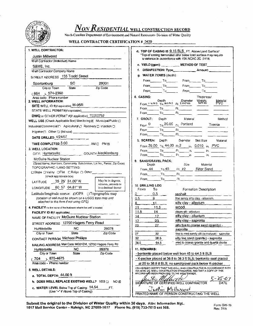
NON ESIDENTIAL WELL CONSTRUCTION RECORD
North Carolina Department of Environment and Natural Resources- Division of Water Quality
WELL CONTRACTOR CERTIFICATION # 3439
1. WELL CONTRACTOR:
Justin MillwoodWell Contractor (Individual) Name
S&ME, Inc.Well Contractor Company Name
STREET ADDRESS 155 Tradd Street
Spartanburg SC 29301City or Town State Zip Code
(864 )- 574-2360Area code- Phone number
2. WELL INFORMATION:
SITE WELL ID #(if applicable) M-95R
STATE WELL PERMIT#(it applicable)
DWQ or OTHER PERMIT #(if applicable) 70000752
WELL USE (Check Applicable Box) Monitoring 91 Municipal/Public El
Industrial/Commercial El Agricultural C1 Recovery E Injection El
Irrigationo] Other El (list use)
DATE DRILLED 4/24/07
TIME COMPLETED 5:00 AM 0l PM Ei
3. WELL LOCATION:
CITY: Huntersville COUNTY Mecklenburg
McGuire Nuclear Station
d. TOP OF CASING IS 0.16 BLS FT. Above Land Surface**Top of casing terminated at/or below land surface may require
a variance in accordance wvth 15A NCAC 2C .0118.
e. YIELD (9pm): METHOD OF TEST
f. DISINFECTION: Type _ Amount
g. WATER ZONES (depth):
From - To_ From - To
From_ To_ From_ To
From_ To_ From - To
6. CASING: Thickness/Depth Diameter Vel h aterial
From 0-16BLS To 30 BLs Ft. 2 inches P4
From - To_ Ft._
From_ To_ Ft._
7. GROUT: Depth Material Method
From 0 To 20,00 Ft. Portland Tremie
From_ _ To_ Ft.
From_ To_ Ft.
8. SCREEN: Depth Diameter Slot Size Material
From 39-00 To 44.00 Ft. 2 in, 0.010 in. PVCFrom _ To _ Ft. in, in.
From _ To . Ft. in. in.
9. SANDIGRAVEL PACK:Depth Size Material
From 44 To 45 Ft. #2 Filter Sand
From To Ft.
From To_ Ft._
10. DRILLING LOGFrom To Formation Description
(Street Name, Numbers, Community, Subdivision, Lot No., Parcel, Zip Code)TOPOGRAPHIC / LAND SETTING:
E Slope E Valley El Flat El Ridge El Other(check appropriate box)
LATITUDE 35 25' 51.00" N May be in degrees,minutes, seconds or
LONGITUDE 80 57' 04.81" W in a decimal formal
Latitude/longitude source: u GPS El Topographic map(location of well must be shown on a USGS topo map andattached to this form if not using GPS)
4. FACILITY- is the name of the business where the well is located.
FACILITY ID #(if applicable)
NAME OF FACILITY McGuire Nuclear Station
STREET ADDRESS 12700 Hagers Ferry Road
Huntersville NC 28078
0 0.50.5 88 1111 11.511.5 1414 1717 2323 27
27 32
32 36.536.5 64.5
asphaltline sandy silty clay - alluvium
silty clay - alluviumwoodclavev silt - ailluviumsilty clay - alluviumsilty clay - saprolitesilty fine to coarse sand (granitic) -
saprolitefine to med sandy silt (schistose) - saproliteCity or Town State Zip Code
CONTACT PERSON Michael Phillips
MAILING ADDRESS Mail Code MG01 EM, 12700 Hagers Ferry Rd
Huntersville NC 28078City or Town State Zip Code
silty fine sand (wranitic) - saprolitemed to coarse granite and quartz diorite
11. REMARKS:- bentonite placed below well from 45 to 64.5 ft BLS
- K-packer placed at 36.8 to 38.3 ft BLS; bentonite seal placed( 704 ). 875-4675
Area code - Phone number
5. WELL DETAILS:
a. TOTAL DEPTH: 44.00 ft
b. DOES WELL REPLACE EXISTING WELL? YES El NO 9l
c. WATER LEVEL Below Top of Casing: 14.54 FT.(Use "+" if Above Top of Casing)
at 20 to 36.8 It BLS: no sand/qravel pack below K-packerI DO HEREBY CERTIFY THAT THIS WELL WAS CONSTRUCTED IN ACCORDANCE WITH15A NCAC 2•, WELL CONSTRUCTION STANDARDS, AND THATA COPY OF THISRECORD BEEN PROV"DE T'.!HE WF.%A WNER.
1514IATURE OF CERTIFIED WELL CONTRACTOR
.1- Y ,A A#4it,00DATE
PRINTED NAME OF PERSON CONSTRUCTING THE WELL
Submit the original to the Division of Water Quality within 30 days. Attn: information Mgt.,1617 Mail Service Center- Raleigh, NC 27699-1617 Phone No. (919) 733-7015 ext 568.
Form GW- I bRev. 7/05

NON RESIDENTIAL WELL CONSTRUCTION RECORD
North Carolina Department of Environment and Natural Resources- Division of Water Quality
WELL CONTRACTOR CERTIFICATION # 3439
1. WELL CONTRACTOR:
Justin MillwoodWell Contractor (Individual) Name
S&ME, Inc.Well Contractor Company Name
STREET ADDRESS 155 Tradd Street
Spartanburg SC 29301City or Town State Zip Code
(864 ). 574-2360Area code- Phone number
2. WELL INFORMATION:
SITE WELL ID #(if applicable) M-96
STATE WELL PERMIT#(if applicable)_
DWQ or OTHER PERMIT #(if applicable) 70000752
WELL USE (Check Applicable Box) Monitoring Ml Municipal/Public ED
Industrial/Commercial 0 Agricultural El Recovery - Injection El
Irrigationo Other 0 (list use)
DATE DRILLED 5/4/07
TIME COMPLETED 5:00 AM 0 PM Z
3. WELL LOCATION:
CITY: Huntersville COUNTY Mecklenburg
McGuire Nuclear Station
d. TOP OF CASING IS 2.98 FT. Above Land SurfaceW*Top of casing terminated avor below land surface may requirea variance in accordance with 15A NCAC 2C .0118.
e, YIELD (8pm): METHOD OF TEST
f. DISINFECTION: Type _ Amount
g. WATER ZONES (depth):
From_ To_ From_ To
From - To_ From_ To
From_ To_ From - To
6. CASING: Thickness/Depth Diameter Ve g trial
From 2.90ALS To 19.0 BLS Ft. 2 inches
From_ To_ Ft._
From_ To_ Ft.
7. GROUT: Depth Material Method
From 0 To 15.00 Ft. Portland Tremie
From To_ Ft.
From_ To_ Ft._
8. SCREEN: Depth Diameter Slot Size Material
From 19.00 To 34.00 Ft.2
in. 0.010 in. PVC
From_ To Ft. in. in.
From_ To_ Ft, in. in.
9. SAND/GRAVEL PACK:
Depth Size Material
From 17.00 To 34.00 Ft. #1 Filter Sand
From To Ft._
From To _ Ft,.
10. DRILLING LOGFrom To Formation Description
0 8 fine sandy clayey silt - fill8 12 fine sandy clayey silt - saprolite
12 34 slightly clayey fine sandy silt -.saprolite
11. REMARKS:
(Street Name, Numbers, Community, Subdivision, Lot No., Parcel, Zip Code)
TOPOGRAPHIC / LAND SETTING:
[ISlope ElValley El]Flat 0 Ridge [] Other(check appropriate box)
LATITUDE 35 25' 52,96" N May be in degrees,minutes, seconds or
LONGITUDE 80 56' 59.27" W in a decimal for-mat
Latitude/longitttde source: j oGPS 0 Topographic map(location of well must be shown on a USGS topo map andattached to this form if not using GPS)
4. FACILITY. is the name of the business where the well is located.
FACILITY ID #(if applicable)
NAME OF FACILITY McGuire Nuclear Station
STREET ADDRESS 12700 Hagers Ferry Road
Huntersville NC 28078
City or Town State Zip Code
CONTACT PERSON Michael Phillips
MAILING ADDRESS Mail Code MG01 EM, 12700 Hagers Ferry Rd
Huntersvi~le NC 28078City or Town State Zip Code
704 )- 875-4675Area code - Phone number
5. WELL DETAILS:
a. TOTAL DEPTH: 34.00 It
b. DOES WELL REPLACE EXISTING WELL? YES 0 NO Ml
c. WATER LEVEL Below Top of Casing: 26.73 FT.(Use "+" if Above Top of Casing)
I DO HEREBY CERTIFY THAT THIS WELL WAS CONSTRUCTED IN ACCORDANCE WITH15A NcAC 2C~,W ELL CONSTRUCTION STANDARDS, AND THAT A COPY OF THISRECORD HA BEEN PROVIDED TO TIE WELL 7NER.
' 4r),ISIGAr'URE OF CERTIFIED WELL CONTRACTOR DATE
PRINTED NAME OF PERSON CONSTRUCTING THE WELL
Submit the original to the Division of Water Quality within 30 days. Attn: Information Mgt.,1617 Mail Service Center - Raleigh, NC 27699-1617 Phone No. (919) 733-7015 ext 568.
Form GW-lbRev. 7/05
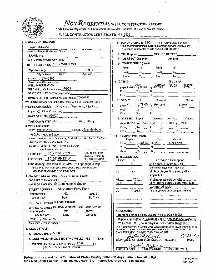
NON RESIDENTIAL WELL CONSTRUCTION RECORDNorth Carolina Department of Environment and Natural Resources- Division of Water Quality
WELL CONTRACTOR CERTIFICATION #' 3439
1. WELL CONTRACTOR:
Justin MillwoodWell Contractor. (Individual) Name
S&ME, Inc.
Well Contractor Company Name
STREET ADDRESS 155 Tradd Street
Spartanburg SC 29301
City or Town State Zip Code
(864 )- 574-2360Area code- Phone number
2. WELL INFORMATION:
SITE WELL ID #(if applicable) M-96R
STATE WELL PERMIT#t(it applicable)
DWQ or OTHER PERMIT #(if applicable) 70000752
WELL USE (Check Applicable Box) Monitoring Z) Municipal/Public El
Industrial/Commercial E0 Agricultural El Recovery [3 Injection El
Irrigationo Other El (list use)
DATE DRILLED 4/26/07
TIME COMPLETED 5:00 AM El PM g]
3. WELL LOCATION:
CITY: Huntersville COUNTY Mecklenburg
McGuire Nuclear Station(Street Name, Numbers, Community, Subdivision, Lot No., Parcel, Zip Code)
TOPOGRAPHIC / LAND SETTING:
E Slope El Valley l Flat E Ridge El Other(check appropriate box)
LATITUDE 35 25' 52.97" N Maybeindegrees,minutes, seconds or
LONGITUDE 80 56' 59.33" W in a decimal format
Latitude/longitude source: u3GPS ElTopographic map(location of well must be shown on a USGS topo map and
attached to this form if not using GPS)
4. FACILITY- is the name of the business where the welt is located.
FACILITY ID #(if applicable)
NAME OF FACILITY McGuire Nuclear Station
STREET ADDRESS 12700 Hagers Ferry Road
Huntersville NC 28078
d. TOP OF CASING 18 2.85 FT. Above Land Surface**Top of casing terminated at/or below land surface may require
a variance in accordance with 15A NCAC 2C .0118.
e. YIELD (gpm): METHOD OF TEST
f. DISINFECTION: Type Amount
g. WATER ZONES (depth):
From To From To
Frornm To_ _ From_ To
From _To_ From_ To
6. CASING: Thickness/Depth Diameter -• Ihrial
From 2.85ALS .To 2.081LS Ft. 2 inches cL
From - To Ft._
From To_ Ft..
7. GROUT: Depth Material Method
From 0 To 78.00 Ft. Portland Tremie
From To Ft.
From_ To Ft.__-
B. SCREEN: Depth Diameter Slot Size Material
From 82.00 To 87.00 Ft.2 in. 0.010 in. PVCFrom _ To - Ft. in. in.
From _ To _ Ft. in. _ in.
9. SAND/GRAVEL PACK:
Depth Size Material
From 87 To 88.00 Ft. #2 Filter Sand
From To_ Ft._
From To___ Ft._
10. DRILLING LOGFrom To Formation Description
.0 8 fine sandy clayey silt - fill
8 12 tine sandy clayey silt - saprolite
12 47 slightly clayey fine sandy silt -saprolite
47 52.5 silly fine to med sand - saprolite
52,5 80 silty fine to coarse sand (granitic) -
weathered rock
80 99.57 fine to coarse grained quartz diorite
11. REMARKS:- bentonite placed below well from 88 to 99.57 ft BLS
City or Town State Zip Code
CONTACT PERSON Michael Phillips
MAILING ADDRESS Mail Code MG01EM, 12700 Hagers Ferry Rd
Huntersville NC 28078City or Town State Zip Code
704 o 875-4675Area code - Phone number
5. WELL DETAILS:
a. TOTAL DEPTH: 87.00 ft
b. DOES WELL REPLACE EXISTING WELL? YES El NO 93
c, WATER LEVEL Below Top of Casing: 26.6 FT.(Use "+" if Above Top of Casing)
- K-packer placed at 79.8 to 81.3 ft BLS; bentonite seal placed at
78 to 79.8 ft BLS; no sand/oravel oack below K-packerI DO HEREBY CERTIFY THAT THIS W ELL WAS CONSTRUCTED IN ACCORDANCE WITH15A NCAC 2C, W E41L CONSTRUCTION STANDARDS, AND THAT A COPY OF THISRECORD HAS BAN PROVIDED TOITH WELL 9WNAR.
SIGNATRE OF CERTIFIED WELL CONTRACTOR DATE
PRINTED NAME OF PERSON CONSTRUCTING THE WELL
Submit the original to the Division of Water Quality within 30 days. Attn: Information Mgt.,1617 Mail Service Center- Raleigh, NC 27699-1617 Phone No. (919) 733-7015 ext 568.
Form GW-IbRev. 7/05

NON RESIDENTIAL WELL CONSTRUCTION RECORD
North Carolina Department of Environment and Natural Resources- Division of Water Quality
WELL CONTRACTOR CERTIFICATION fi 3439
1. WELL CONTRACTOR:
Justin MillwoodWell Contractor (Individual) Name
S&ME, Inc.Well Contractor Company Name
STREET ADDRESS 155 Tradd Street
Spartanburg SC 29301
City or Town State Zip Code
864 )- 574-2360Area code- Phone number
2. WELL INFORMATION:
SITE WELL ID #(if applicable) M-97
STATE WELL PERMIT#(if applicable)_
DWO or OTHER PERMIT #(if applicable) 70000752
WELL USE (Check Applicable Box) Monitoring 0t Municipal/Public 12
Industrial/Commercial 0 Agricultural 0 Recovery 0 Injection 0
Irrigationo Other C2 (list use)
DATE DRILLED 5/8/07
TIME COMPLETED 5:00 AM C PM El
3. WELL LOCATION:
CITY: Huntersville COUNTY Mecklenburg
McGuire Nuclear Station
(Street Name, Numbers, Community, Subdivsion, Lot No., Parcel, Zip Code)
TOPOGRAPHIC / LAND SETTING:
[]Slope OValley DFlat r2Ridge C2 Other/, (check appropriate box)
LATITUDE 35 25' 51.65" N May be in degrees,m inutes, seconds or
LONGITUDE 80 56' 51.19" W is) a decimal tbormat
Latitude/longitude source: uGPS oTopographic map(location of well must be shown on a USGS topo map andattached to this form if not using GPS)
4. FACILITY. is ihe name o Ithe business where the well is socated
FACILITY ID #(if applicable)
NAME OF FACILITY McGuire Nuclear Station
STREET ADDRESS 12700 Hagers Ferry Road
Huntersville NC 28078
d. TOP OF CASING IS 0.34 BLS FT. Above Land Surface**Top of casing terminated at/or below land surface may require
a variance in accordance with 15A NCAC 2C .0118.
e. YIELD (gpm): ___ METHOD OF TEST
f. DISINFECTION: Type________ Amount__
g. WATER ZONES (depth):
From_ _ To_ _ From To
From - To_ From_ To
From. To_ From_ To
6. CASING: Thickness/Depth Diameter VWeiht rytatrial
From 0.34 SLS To 15.0 BLS Ft. 2 inches V
From To Ft.
From- To_ Ft._
7. GROUT: Depth Material Method
From 0.54 To 5.00 Ft. Portland Tremie
From To Ft.
From- To Ft.
8. SCREEN: Depth Diameter Slot Size Material
From 11.00 To 26.00 Ft. 2 in. 0.010 in. PVCFrom _ To _ Ft. in. _ in.
From - To Ft. in. _ in.
9. SANDIGRAVEL PACK:Depth Size Material
From 9.00 To 27.50 Ft. #2 Filter Sand
From To_ Ft.
From To_ Ft._
10. DRILLING LOGFrom To Formation Description
0 0.5 asphalt over gravel0.5 1315 slightly clayey silt- saprolite13-5 22 silt - saprolite22 42 slightly clayey silty sand - saprolite42 51,9 slightly clayey sandy silt - saprolite
51 9 refusal to roller cone drill bit51-9 99.40 fine to medium grained diorite/
quartz diorite
11. REMARKS:bentonite placed below sand pack from 27.5 ft to 99.40 ft
City or Town State Zip Code
CONTACT PERSON Michael Phillips
MAILING ADDRESS Mail Code MG01EM, 12700 Hagers Ferry Rd
Huntersville NC 28078City or Town State
704 ) 875-4675Area code - Phone number
Zip Code
5. WELL DETAILS:
a. TOTAL DEPTH: 26.00 ft
b. DOES WELL REPLACE EXISTING WELL? YES 12 NO In
c. WATER LEVEL Below Top of Casing: 12.70 FT.(Use "+" if Above Top of Casing)
toO HEREBY CERTIFY THAT THIS WELL WAS CONSTRUCTED IN ACCORDANCE WITH15A NCAC 2X WELL CONSTRUCTION STANDAPD, AND THAT A COPY OF THISRECORD HAS BEEN PROVIDED TO HE WEL "'NER.
S7fATURE OF CERTIFrED WELL CONTRACTOR DATE
PRINTED NAME OF PERSON CONSTRUCTING THE WELL
Submit the original to the Division of Water Quality within 30 days. Attn: Information Mgt.,1617 Mail Service Center- Raleigh, NC 27699-1617 Phone No. 1919) 733-7015 ext 568.
Form GW-lbRev. 7/05
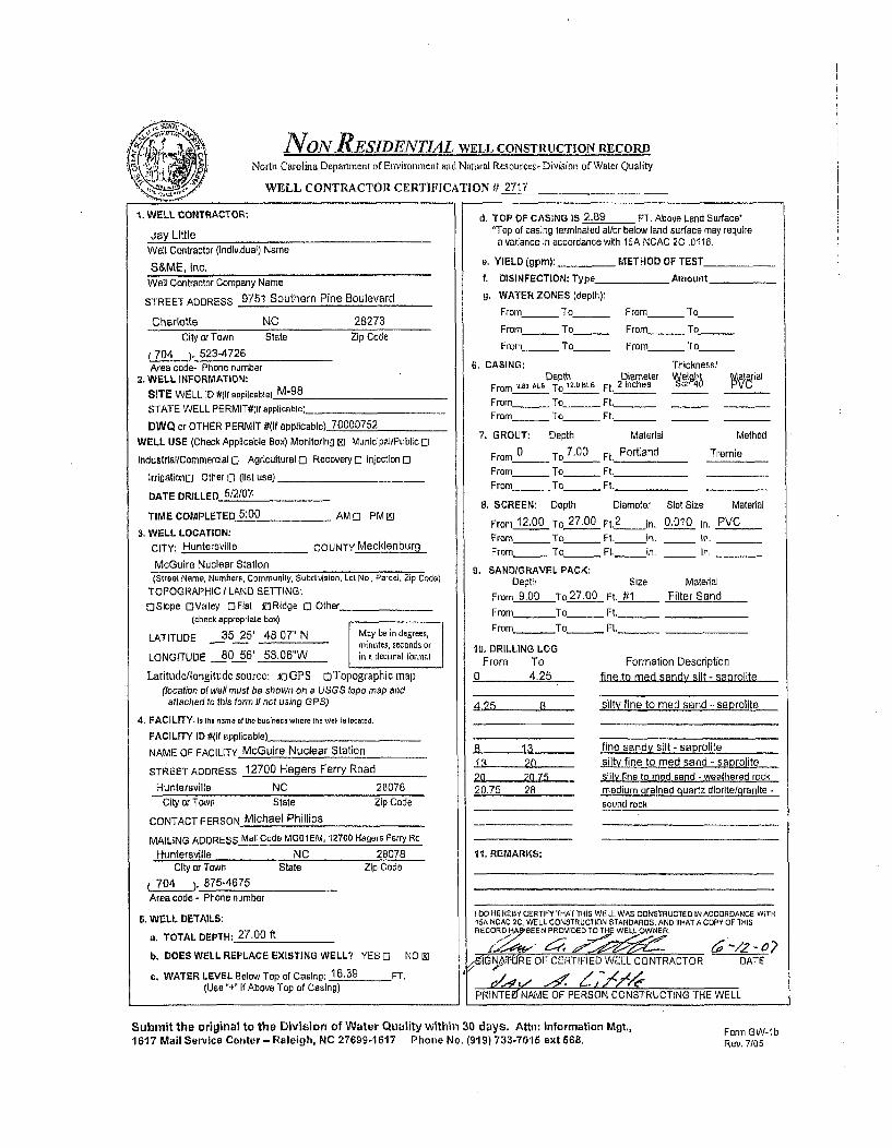
NONJRESIDENTIAL WELL CONSTRUCTION RECORD
North Carolina Department of Environment and Natural Resources-Division of Water Quality
WELL CONTRACTOR CERTIFICATION # 2717
d. TOP OP CASING lS 2.89 FT. Abova Land Surleee1. WELL CONTRACTOR:
Jay LittleWell Contractor (Individual) Name
S&ME, Inc.Well Contractor Company Name
STREET ADDRESS 9751 Southern Pine Boulevard
Charlotte NC 28273
City or Town State Zip Code
(704 ). 523-4726Area code- Phone number
2. WELL INFORMATION:
SITE WELL ID #(If applicable) M-98
STATE WELL PERMIT#(If applicable).
DWQ or OTHER PERMIT #(If applicable) 70000752
WELL USE (Check Applicable Box) Monitoring CD Municipal/Public 0
Industrlal/Commerclal 0 Agricultural 0 Recovery C Iniection 0
IrrigationD Other D (list use) _
DATE DRILLED 5/2/07.
TIME COMPLETED 5:00 AM D PM PD
3. WELL LOCATION:
CITY: Hunteraville COUNTY Mecklenburg
McGuire Nuclear Station
d. TOP OF CASING is 2.139 FT. Above Land Surface'*Top of casing terminated at/or below land surface may require
a variance In accordance with 15A NCAC 2C .0118.
a. YIELD lgpm): _ METHOD OF TEST
f. DISINFECTION: Type Amount
g. WATER ZONES (depth):
From_ To_ From_ To
From_ _ To_ From _ To_
From To_ From___ To
6. CASING: Thickness/Depth Diameter 'Welgh4 arial
From L.sa A=, To 12.0 aLa Ft. 2 inches on 4
From_ To_ Ft. _ _
From - To _ Ft._
7. GROUT: Depth Material Method
From 0 To 7.00 Ft. Portland Tremie
From To__ Ft.
From_ To__ Ft._
U. SCREEN: Depth Diameter Slot Size Material
From 12,00 To 27,00 F1.2
In. 0.010 In, PVCFrom_ To _Ft.__ in. In.From_ To _ Ft, in. In,
9. SAND/GRAVEL PACK:
Depth Size Malerial
From 9.00 To 27.00 Ft. 4_1 Filter Sand
From To_ Ft_
From To Ft._
(Street Name, Numbers, Community, Subdivision, Lot No., Parcel, Zip Code).TOPOGRAPHIC / LAND SETTING:
DSlope DValley OFlat iRidge C Other(check appropriale box)
LATITUDE 35 25' 48,07" N May be in degrees,minutes, seconds or
LONGITUDE 80 56' 58.06"W inia decimal tbroial
Latitude/longitudesource: uGPS oTopographic map(location of well must be shown on a USGS topo map atid
attached to this form if not using GPS)
4. FACILITY- is the nnae osf te business wlere the well Is located.
FACILITY ID #(if applicable)
NAME OF FACILITY McGuire Nuclear Station
STREET ADDRESS 12700 Hagers Ferry Road
Huntersvilla NC 28078
10, DRILLING LOGFrom To
0 4.25
4.25 A
8 1313 2020 207520.75 28
11. REMARKS:
Formation Descriptionfine to mad sandy silt - saprolite
silty fine to med sand -. saprolite
fine sandy silt - saprolite
.silty fine to med sand - saprolite
silty fine to mad sand - weathered rockmedium grained quartz diorite/,granlte -
sound rockCity or Town State
CONTACT PERSON Michael Phillips
Zip Code
MAILING ADDRESS Mall Code MG01EM, 12700 Hagers Ferry Rd
Huntersville NC 28078City or Town State
704 ). 875-4675
Area code - Phone number
Zip Code
6. WELL DETAILS:
a. TOTAL DEPTH: 27.00 ft
b. DOES WELL REPLACE EXISTING WELL? YES C NO []
c. WATER LEVEL Below Top of Casing: 16.39 FT.(Use "+ If Above Top of Casing)
1 00 HEREBY CERTIFY THAT THIS WELL WAS CONSTRUCTED IN ACCORDANCE WiTH15A NCAC 2C, WELL CONSTRUCTION STANDARDS, AND THAT A COPY OF THISRECORD Sp'5EEN PROVIDED TO TH WELL OWNER.
>
,'stGNA-T-URE OF CERTIFIED WELL CONTRACTOR DATE
PRINTEKNAME OF PERSON CONSTRUCTING THE WELL
Submit the original to the Division of Water Quality within 30 days. Attn: Information Mgt.,1617 Mail Service Center - Raleigh, NC 27699-1617 Phone No. (919) 733-7015 ext 568.
Form GW-lbRev. 7/05

IVNONRESIDENTIAL WELL CONSTRUCTION RECORD
North Carolina Department of Environment atd Natural Resources- Division of Water Quality
WELL CONTRACTOR CERTIFICATION # 2717
1. WELL CONTRACTOR:
Jay LittleWell Contractor (Individual) Name
S&ME, Inc,Well Contractor Company Name
STREET ADDRESS 9751 Southern Pine Boulevard
Charlotte NC 28273City or Town State Zip Code
(704 ). 523-4726Area code- Phone number
2. WELL INFORMATION:
SITE WELL ID #(it applicable) M-98R
STATE WELL PERMIT#lIt applicable)_
DWO or OTHER PERMIT 4(if applicable) 70000752
WELL USE (Check Applicable Box) Monitoring R) Municipal/Public 0
Industrial/Commercial 0 Agricultural 0 Recovery 0 Injection D
IrrigatlonD Other 0 (list use)
DATE DRILLED 4/25107
TIME COMPLETED 5:00 AM D PMES
3. WELL LOCATION:
CITY: Huntersville COUNTY Mecklenburg
McGuire Nuclear Station(Street Name, Numbers, Community, Subdivision, Lot No,, Parcel, Zip Code)
TOPOGRAPHIC / LAND SETTING:
OSlope OValley DFlat f3Ridge 0 Other(check appropriate box)
LATITUDE 35 25' 48.12" N May be in degrees,minutes, seconds or
LONGITUDE 80 56' 58,10"W in a decimal ibmrat
Latitude/longitudesource: ;UGPS oTopographicrnap(location of well must be shown on a USGS tope map and
attached to this form if not using GPS)
4, FACILITY. Is the name af the buslness where the well 15Is calec.
FACILITY ID #(if applicable)_
NAME OF FACILITY McGuire Nuclear Station
STREET ADDRESS 12700 Hagers Ferry Road
Huntersville NC 28078
d, TOP OF CASING IS 3.22 FT. Above Land Surface*'Top of casing terminated ator below land surface may requirea variance in accordance with 15A NCAC 2C .0118.
a. YIELD (gpm): _ METHOD OF TEST
f. DISINFECTION: Type AAmount
g. WATER ZONES (depth):
From- To_ From - To
From- To _ From - To
From To_ From_ __ To_______
6, CASING: Thickness/Depth Diameter Weighl PýV J al
From 3.52 ALS To 42.6BLe Ft. 2 Inches ch 4
From - To - Ft.__
From_ To_ Ft._ _
7. GROUT: Depth Material Method
From 0 To 40.80 Ft. Portland Tremie
From _ To__ Ft.From - To_ Ft.
B. SCREEN: Depth Diameter Slot Size Material
From 42.60 To 47.60 Ft.2
In. 0.010 In. PVCFrom____ To_ _ Ft. In. _ in.
From To_ Ft. in. in,
g. SANDIGRAVEL PACK:
Depth Size Material
From 47.60 To48.60 Ft. #1 Filter Sand
From To_ Ft.
From To Ft._
10, DRILLING LOGFrom To Formation Description
0 4.25 fine to med sandy silt - saprolite
4.25 8 silty fine to med sand - saprolite
8 13 fine sandy silt - saprolite13 20 silly fine to med sand - saprolite
20 20.75 silty fine to med sand - weathered rock
20,75 49,7 medium Drained qcuariz diorlteqranlle -sound rock
11. REMARKS:- K-packer placed at 41.65 to 41.9 ft BLS; bentonite seal placed
at 40.8 to 41.65 ft BLS
City or Town State Zip Code
CONTACT PERSON Michael Phillips
MAILING ADDRESS Mall Code MG01EM, 12700 Hagers Ferry Rd
Huntersville NC 28078City or Town State Zip Code
704 ). 875-4675Area code - Phone number
5. WELL DETAILS:
a. TOTAL DEPTH: 47.60 ft
b. DOES WELL REPLACE EXISTING WELL? YES 0 NO$3
c. WATER LEVEL Below Top of Casing: 19.52 FT,(Use "+" If Above Top of Casing)
- bentonite placed below well from 48.6 to 49.7 ft BLSI DO HEREBY CERTIFY THAT THIS WELL WAS CONSTRUCTED IN ACCORDANCE WITHISA NCAC 2C, WELL CONSTRUCTION STANDARDS, AND THAT A COPY OF THISRECOROH EEN PROVIDED TO THE WELL OWNER.
d'GNAWM OF CERTIFIED WELL CONTRACTOR DATE
PRNTz NAE F2, P C T HPt NTLI AME OF PERSON CONSTRUCTING THE WELL
Submit the original to the Division of Water Quality within 30 days, Attn: Information Mgt.,1617 Mail Service Center- Raleigh, NC 27699-1617 Phone No. (919) 733-7015 ext 568.
Form GW-lbRev. 7/05

NoN RESIDENTIAL WELL CONSTRU CTION RECORDNorth Carolina Department of Environmen.t and Natural Resources- Division of Water Quality
WELL CONTRACTOR CERTIFICATION # 2717
1. WELL CONTRACTOR:
Jay LittleWell Contractor (individual) Name
SAME, Inc.Well Contractor Company Name
STREET ADDRESS 9751 Southern Pine Boulevard
Charlotte NC 28273City or Town State Zip Code
(704 ). 523-4726Area code- Phone number
2. WELL INFORMATION:
SITE WELL iD #(if applicable) M-10OR
STATE WELL PERMIT#(It applicable)_____________
DWQ or OTHER PERMIT #(if applicable) 70000752
WELL USE (Check Applicable Box) Monitoring 91 Munlcipal/Pubiic 0
Industrlal/Commercial U Agricultural [ RecoveryU Injection U
Irrigalionr Other c3 (list use)
DATE DRILLED 4/24/07
TIME COMPLETED 5:00 AM E PM E)
3. WELL LOCATION:
CITY: Huntersville COUNTY Mecklenburg
McGuire Nuclear Station
d. TOP OF CASING IS 2.96 FT. Above Land Surface**Top of casing terminated at/or below land surface may require
a variance In accordance with 15A NCAC 2C .0118.
e. YIELD (Upm): __ METHOD OF TEST
f. DISINFECTION: Type_____________ Amount
g. WATER ZONES (depth):
From_ To______ From To
From_ To_ From_ To_
From To _ From_____ To___
6. CASING: Thickness/Depth Diameter V%19 0ial
From aI. To "I's Ft. 2 Inches
From_ To_ Ft._ _
From- To - Ft._ _
7. GROUT: Depth Material Methad
From 0_ To 30.00 Ft Portland Tremie
From _ To___ Ft.
From.____ To- Ft_
8. SCREEN: Depth Diameter Slot Size Material
From 42.00 To 47.00 Ft.2
in. 0.010 in. PVCFrom _ To___ Ft. In. In.From _ To Ft. in. in.
9. SAND/GRAVEL PACK:Depth Size Material
From 47.00 To 50.00 Ft. #1 Filter Sand
From To_ Ft.
From To_ Ft.
10. DRILLING LOGFrom To Formation Description
0 0.5 gravel
0C5 30 sandy silty clay
30 40.25 fine to coarse sand - weathered-rock (granitic)
40.25 60.0 fine grained ,granite - sound rock
11. REMARKS:
- K-packer placed at 41.25 to 41.5 ft BLS: bentonite seal olaced
(Street Name, Numbers, Community, Subdivision, Lot No., Parcel, Zip Code)TOPOGRAPHIC / LAND SETTING:
0Slope oValley U Fiat JDRIdge U Other(check appropriate box)
LATITUDE 35 25' 47.38" N May be in degrees,minutes, seconds or
LONGITUDE 80 57' 07.53"W in s decimal format
Latitude/longitude source: SoGPS oTopographic map
(location of well must be shown on a USGS lopo map endattached to this form if not using GPS)
4. FACILITY- Is the name of the business whero the well is located.
FACILITY ID #(if applicable)
NAME OF FACILITY MoGuire Nuclear Station
STREET ADDRESS 12700 Hagers Ferry Road
Huntersville NC 28078
City or Town State Zip Code
CONTACT PERSON Michael Phillips
MAILING ADDRESS Mail Code MGO1EM, 12700 Hogers Ferry Rd
Huntereville NC 28078City or Town State Zip Code
704 _ )- 75-4675Area code- Phone number
5. WELL DETAILS:
a. TOTAL DEPTH: 47.00 ft
b. DOES WELL REPLACE EXISTING WELL? YES 0 NO ZI
c. WATER LEVEL Below Top of Casing: 31.38 FT.(Use "+" If Above Top of Casing)
at 30.0 to 41,25 ft BLS- bentonite placed below well from 50.0 to 60.0 It BLSI 00 HEREBY CERTIFY THAT THIS WELL WAS CONSTRUCTED IN ACCORDANCE WITH16A NCAC 2C, WELL CONSTRUCTION STANDARDS, AND THAT A COPY OF THISRECORDc S eEEN PROVIDED TO THE WELL OWNER.
6 -~* >,VG•W'URE OF CERTIFIED WELL CONTRACTOR
41./.€, --7 Z'.41DATE
PRINTEO NAME OF PERSON CONSTRUCTING THE WELL
Submit the original to the Division of Water Quality within 30 days. Attn: Information Mgt.,1617 Mail Service Center - Raleigh, NC 27699-1617 Phone No. (919) 733-7015 ext 568.
Form GW-lbRev. 7/05

S&MELETTER OF TRANSMITTAL
S&ME, Inc.155 Tradd StreetSpartanburg, South Carolina 29301(864) 574-2360Fax (864) 576-8730
Mecklenburg County Health Department
DATE 07/18/07 1 JOB NO. 1264-06-724
ATTENTION Shawna CaldwellRE: Monitor Well Registration Form
McGuire Nuclear Station
Well Application Permit No. 70000752
Land Use & Environmental Serice Agency
Groundwater & Wastewater Services
WE ARE SENDING YOU E Attached FD Under separate cover via _ the following items:- Shop drawings - Prints D- Plans 0 Samples EII Specifications
[-I Copy of letter F- Report lI CD Z Monitor Well Registration
COPIES DATE NO. DESCRIPTION
1 7/18/07 Mecklenburg County Monitor Well Registraion
THESE ARE TRANSMITTED as checked below:F1 For approvalFZ For your useE] As requestedE- For review and comment F[_F-- FOR BIDS DUE [_ PRINTS RETURNED AFTER LOAN TO US
REMARKS Based on our July 16, 2007 telephone conversation, S&ME (on behalf of Duke
Energy) is submitting the Monitor Well Registration Form which was omitted from the
June 13, 2007 Non-Residential Well Contruction Records-Submittal #2 for McGuire Nuclear
Station.
IF ENCLOSURES ARE NOT AS NOTED, PLUAS-NOTIIS AT ONCE.
This Letter of Transmittal and the documents accompanying this Letter of Transmittal contain information from S&ME, Inc., which Is confidential and legallyprivileged. The information is intended only for the use of the individual or entity named on the Letter of Transmittal. If you are not the intended recipient,you are hereby notified that any disclosure, copying, distribution or the taking of any action in reliance on these documents is strictly prohibited.

Mecklenburg CountyLand Use & Environmental Service AgencyGroundwater & Wastewater Services700 N. Tryon St., Suite 211Charlotte, NC 28202Phone: (704) 336-5103Fax: (704) 336-6894 Monitor Well Registration
Staff Use OnlyDate Received:____
Is this Registration for a well or wells that existed prior to January 01, 2005?. No
Enter your Subsurface Investigation Permit #:, 70000752 Date Well Installation Began: 4-6-07
Date Well Installation Complete: 5-8-07
Site/Contact Information Bill to Owner/Agent Name: - Duke Energy / Michael Phillips
Name of Site: McGuire Nuclear Station Owner/Agent Address: Mail Code MG01EM 12700 Hagers Ferry Rd.
Site Address: 12700 Haaers Ferrv Road Owner/Agent Phone #: Huntersville, NC 28078•704-875-4675
Site Tax Parcel ID: 00119103 Driller Certification #: 3439 & 2717
Type of Registration
This registration is for (check all that apply):
X Unregistered Permanent Monitor Wells E Yearly Update of Permanent Monitor Wells
n Temporary Monitor Wells
The following information must be completed for each tax parcel on which monitor wells have been installed:
On-Site Monitor Wells Tax Parcel # Tax Parcel # Tax Parcel #
Type of Well # Present Type of Well # Present Type of Well # Present Type of Well # Present
Temporary* Temporary* Temporary* Temporary*
Permanent 12 Permanent Permanent Permanent
Sparge Sparge Sparge Sparge
Vapor Extraction Vapor Extraction Vapor Extraction Vapor Extraction
Recovery Recovery Recovery Recovery
Injection Injection Injection Injection
Vapor Monitoring Vapor Monitoring Vapor Monitoring Vapor Monitoring
Piezometer Piezometer Piezometer Piezometer
Groundwater Standard Groundwater Standard Groundwater Standard Groundwater Standard
Exceeded? Exceeded? Exceeded? Exceeded?
Tax Parcel # Tax Parcel # Tax Parcel # Tax Parcel #
Type of Well # Present Type of Well # Present Type of Well # Present Type of Well # Present
Temporary* Temporary* Temporary* Temporary*
Permanent Permanent Permanent Permanent
Sparge Sparge Sparge Sparge
Vapor Extraction Vapor Extraction Vapor Extraction Vapor Extraction
Recovery Recovery Recovery Recovery
Injection Injection Injection Injection
Vapor Monitoring Vapor Monitoring Vapor Monitoring Vapor Monitoring
Piezometer Piezometer Piezometer Piezometer
Groundwater Standard Groundwater Standard Groundwater Standard Groundwater Standard
Exceeded? Exceeded? Exceeded? Exceeded?
*Selection of Temporary Well requires monitor well abandonment forms also be filed. Failure to file abandonment forms will result in the well beingconsidered permanent and cause the well owner to be billed the appropriate fee.
JLS 12/13/04 Final

SS&ME
June 13, 2007
North Carolina Department of Environment and Natural ResourcesDivision of Water Quality1617 Mail Service CenterRaleigh, North Carolina 27699-1617
ATTN: Information Management
Reference: NON-RESIDENTIAL WELL CONSTRUCTION RECORDS - SUBMITTAL #2McGUIRE NUCLEAR STATION12700 Hagers Ferry RoadHuntersville, North CarolinaS&ME Project No. 1264-06-724
Ladies and Gentlemen:
On behalf of Duke Energy, S&ME, Inc. (S&ME) is submitting the enclosed completed and signed Non-Residential Well Construction Records for the following twelve (12) groundwater monitoring wellsinstalled at the McGuire Nuclear Station (MNS) site:
* M-92 • M-93R • M-96 ° M-98• M-92R ° M-95 * M-96R • M-98R• M-93 ° M-95R • M-97 • M-100R.
Duke Energy is voluntarily installing groundwater monitoring wells at MNS as part of a site-widehydrogeologic evaluation. S&ME will continue to submit these Non-Residential Well ConstructionRecords on a periodic basis as well installations are completed, this being the second submittal (i.e.,Submittal #2).
On behalf of Duke Energy, S&ME thanks you for your receipt of these records. Should you have anyquestions or need additional information, please contact us.
Sincerely,S&ME, Inc.
Scott E. Dacus, P.G.
Project Geologist S
enclosures
cc: Messrs. Steve LeRoy, Ed Sullivan, Tim Hunsucker;, Duke Energy
S.' ENV1RONI20061I264 Projectsl6406724 McGuire Nuclear Groundwater StudyWCDENR Well Recordslncdenr well records submittal 2.doc
S&ME, INC. / 155 Tradd Street / Spartanburg, SC 29301 / p 864.574.2360 f 864.576.8730
1 Marcus Drive / Greenville, SC 29615 / p 864-232-8987 / www.smeinc.com

NON RESIDENTIAL WELL CONSTRUCTION RECORDNorth Carolina Department of Environment and Natural Resources- Division of Water Quality
WELL CONTRACTOR CERTIFICATION # 2717
1. WELL CONTRACTOR:
Jay LittleWell Contractor (Individual) Name
S&ME, Inc.Well Contractor Company Name
STREET ADDRESS 9751 Southern Pine Boulevard
Charlotte NC 28273City or Town State Zip Code
(704 ). 523-4726Area code- Phone number
2. WELL INFORMATION:
SITE WELL ID #(if applicable) M-92STATE WELL PERMIT#(if applicable)
DWQ or OTHER PERMIT #(if applicable) 70000752
WELL USE (Check Applicable Box) Monitoring Mj Municipal/Public 0
Industrial/Commercial M Agricultural 0 Recovery 0 Injection 0
IrrigationE] Other 0 (list use)
DATE DRILLED 4/17/07
TIME COMPLETED 5:00 AMo PM E
3. WELL LOCATION:
CITY: Huntersville COUNTY Mecklenburg
McGuire Nuclear Station
d. TOP OF CASING IS 2.94 FT. Above Land Surface**Top of casing terminated at/or below land surface may requirea variance in accordance with 15A NCAC 2C .0118,
e. YIELD (gpm): _ METHOD OF TEST
f. DISINFECTION: Type _ Amount
8. WATER ZONES (depth):
From To From To
From___ T"o From - To
From - To - From - To
6. CASING: Thickness/Depth Diameter eih4 Matrial
From 2.94 ALS To ISSOnLs Ft. 2inches
From - To_ Ft._
From_ To Ft._
7. GROUT: Depth Material Method
From 0 To 10.00 Ft. Portland Tremie
From To Ft.
From_ To Ft.
8. SCREEN: Depth Diameter Slot Size Material
From 19.50 To 34.50 Fl.2 in. 0.010 in. PVCFrom To Ft. in. in.
From_ To_ Ft. in. in.
9. SANDIGRAVEL PACK:Depth Size Material
From 12.00 To 34.50 Ft. #1 Filter Sand
From To_ Ft._
From To_ Ft._
10. DRILLING LOGFrom To Formation Description
0 26 fine sandy silty clay - fill
26 34 fine sandy silty clay, with organics-.alluvium
34 35 fine sandy silty clay - saprolite
11. REMARKS:
(Street Name, Numbers, Community, Subdivision, Lot No., Parcel, Zip Code)TOPOGRAPHIC / LAND SETTING:
0OSlope 0 Valley OFlat U Ridge 0 Other_______(check appropriate box)
LATITUDE 35 25' 57.70" N May be in degrees,minutes, seconds or
LONGITUDE 80 57' 10.80"W ina decimal format
Latitude/longitude source: rjGPS LITopographic map(location of well must be shown on a USGS topo map and
attached to this form if not using GPS)
4. FACILITY. is the name of the business where the well is located.
FACILITY ID #(if applicable)_
NAME OF FACILITY McGuire Nuclear Station
STREET ADDRESS 12700 Hagers Ferry Road
Huntersville NC 28078City or Town State Zip Code
CONTACT PERSON Michael Phillips
MAILING ADDRESS Mail Code MG01EM, 12700 Hagers Ferry Rd
Huntersville NC 28078City or Town State Zip Code
(704 )- 875-4675
Area code - Phone number
5. WELL DETAILS:
a. TOTAL DEPTH: 34.50 ft
b. DOES WELL REPLACE EXISTING WELL? YES EL NO 91
c. WATER LEVEL Below Top of Casing: 6.99 FT.(Use "+" if Above Top of Casing)
IDO HEREBY CERTIFY THAT THIS WELL WAS CONSTRUCTED IN ACCORDANCE WITH15A NCAC 2C, WELL CONSTRUCTION STANDARDS, AND THAT A COPY OF THISRECORD HAS BEEN PROVIDED TO THE WELL OWNER.
§0NAWRE OF CERTIFIED WELL CONTRACTOR DATE
PRINTED NAME OF PERSON CONSTRUCTING THE WELL
Submit the original to the Division of Water Quality within 30 days. Attn: Information Mgt.,1617 Mall Service Center - Raleigh, NC 27699-1617 Phone No. (919) 733-7015 ext 568.
Form GW-lbRev. 7/05
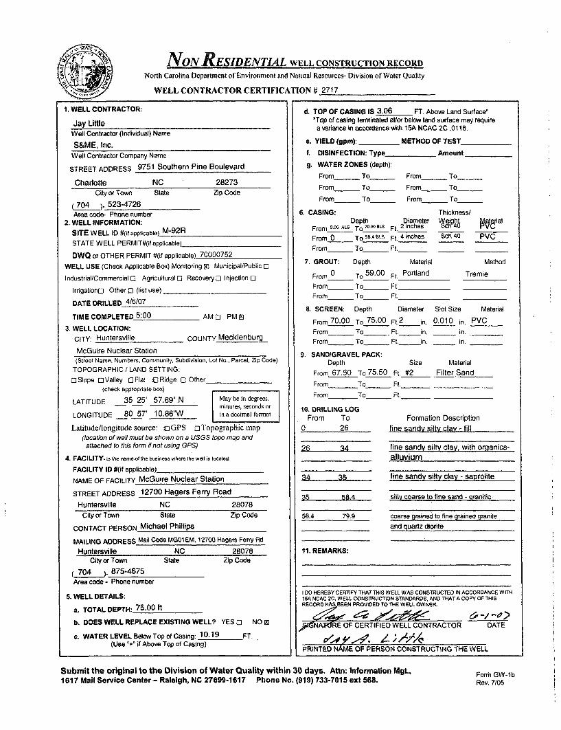
NON RESIDENTIAL WELL CONSTRUCTION RECORD
North Carolina Department of Environment and Natural Resources- Division of Water Quality
WELL CONTRACTOR CERTIFICATION # 2717
1. WELL CONTRACTOR:
Jay LittleWell Contractor (Individual) Name
S&ME, Inc.Well Contractor Company Name
STREET ADDRESS 9751 Southern Pine Boulevard
Charlotte NC 28273City or Town State Zip Code
704 y. 523-4726Area code- Phone number
2. WELL INFORMATION:
SITE WELL ID #(if applicable) M-92R
STATE WELL PERMIT#(if applicable)_
DWQ or OTHER PERMIT #(if applicable) 70000752
WELL USE (Check Applicable Box) Monitoring X1 Municipal/Public Ml
Industrial/Commercial El Agricultural E Recovery 0 Injection ol
Irrigationol Other 0- (list use)
DATE DRILLED 4/6/07
TIME COMPLETED 5:00 AM 0l PM x
3. WELL LOCATION:
CITY: Huntersville COUNTY Mecklenburg
McGuire Nuclear Station
d. TOP OF CASING IS 3.06 FT. Above Land Surface**Top of casing terminated at/or below land surface may require
a variance in accordance with I1SA NCAC 2C .0118.
e. YIELD (9pm): METHOD OF TEST
I. DISINFECTION: Type_ Amount
g. WATER ZONES (depth):
From_ To_ From-____ To__ _
From To From____ To_____
From_ To_ From_____ To______
6. CASING: Thickness/Depth Diameter Wyeight aterial
From 3.06 ALS To 70.O0SLS Ft. 2 inches h WE
From 0 To SA BLS Ft. 4 inches Sch 40 PVC
From To Ft,
7. GROUT: Depth Material Method
From 0 To 59.00 Ft. Portland Tremie
From To Ft.
From_ To Ft.
8. SCREEN: Depth Diameter Slot Size Material
From 70.00 To 75.00 Ft. 2 in. 0.010 in. PVCFrom To Ft. in. 'in.
From _ To _ Ft. in. 'in.
9. SAND/GRAVEL PACK:Depth Size Material
From 67.50 To 75.50 Ft. #2 Filter Sand
From To_ Ft._
From To_ Ft._
(Street Name, Numbers, Community, Subdivision. Lot No., Parcel, Zip Code)
TOPOGRAPHIC / LAND SETTING:
0lSiope 0lValley EFlat -jRidge El Other(check appropriate box)
LATITUDE 35 25' 57.69" N May be in degrees,minutes, seconds or
LONGITUDE 80 57' 10.86"W in a decimal format
Latitude/longitude source: UiGPS oTopographic map(location of well must be shown on a USGS topo map andattached to this form if not using GPS)
4. FACILITY- Is the name of the business where the well is located.
FACILITY ID #(if applicable)
NAME OF FACILITY McGuire Nuclear Station
STREET ADDRESS 12700 Hagers Ferry Road
Huntersville NC 28078
10. DRILLING LOGFrom To
0 26
26 34
34 35
35 58.4
58.4 79.9
11, REMARKS:
Formation Descriptionfine sandy silty clav - fill
fine sandy silty clay, with oroanics-alluvium
fine sandy silty clay - saprolite
siltt coarse to fine sand - granitic
City or Town State Zip Code
CONTACT PERSON Michael Phillips
MAILING ADDRESS Mail Code MG01EM, 12700 Hagers Ferry Rd
Huntersville NC 28078City or Town State Zip Code
704 ) 875-4675
Area code - Phone number
5. WELL DETAILS:
a. TOTAL DEPTH: 75.00 ft
b. DOES WELL REPLACE EXISTING WELL? YES El NO 9i
c. WATER LEVEL Below Top of Casing: 10.19 FT.(Use "+" if Above Top of Casing)
coarse grained to fine grained graniteand auartz diorite
I DO HEREBY CERTIFY THAT THIS WELL WAS CONSTRUCTED IN ACCORDANCE WITH15A NCAC 2C, WELL CONSTRUCTION STANDARDS, AND THATA COPY OF THISRECORD HAS BEEN PROVIOEO TO THE WELL OWNER.
.GNAXRE OF CERTIFIED WELL CONTRACTOR
PRINTED NAME OF PERSON CONSTRUCTING THE WELL
DATE
Submit the original to the Division of Water Quality within 30 days. Attn: Information Mgt.,1617 Mail Service Center- Raleigh, NC 27699-1617 Phone No. (919) 733-7015 ext 568.
Form GW-lbRev. 7/05

NON RESIDENTIAL WELL CONSTRUCTION RECORD
North Carolina Department of Environment and Natural Resources- Division of Water Quality
WELL CONTRACTOR CERTIFICATION # 3439
1. WELL CONTRACTOR:
Justin MillwoodWell Contractor (Individual) Name
S&ME, Inc.Well Contractor Company Name
STREET ADDRESS 155 Tradd Street
Spartanburg SC 29301
City or Town State Zip Code
864 )- 574-2360Area code- Phone number
2. WELL INFORMATION:SITE WELL ID #(it applicable) M-93
STATE WELL PERMIT#(if applicable)
DWQ or OTHER PERMIT #(if applicable) 70000752
WELL USE (Check Applicable Box) Monitoring m Municipal/Public; 0
Industrial/Commercial 0 Agricultural 0 Recovery o Injection El
Irrigationo Other 0 (list use)
DATE DRILLED 4/19/07
TIME COMPLETED 5:00 AM o PM zi
3. WELL LOCATION:
CITY: Huntersville COUNTY Mecklenburg
McGuire Nuclear Station(Street Name, Numbers, Community, Subdivision, Lot No., Parcel, Zip Code)
TOPOGRAPHIC / LAND SETTING:
0 Slope 0 Valley 0 Flat C Ridge 0 Other(check appropriate box)
LATITUDE 35 25' 56.21" N May be in degrees,minutes, seconds or
LONGITUDE 80 57' 07.84" W in a decimal foimat
Latitude/longitude source: uGPS DTopographic map(location of well must be shown on a USGS topo map andattached to this form it not using GPS)
4. FACILITY- is the name of the business where the well is located.
FACILITY ID #(if applicable)_
NAME OF FACILITY McGuire Nuclear Station
STREET ADDRESS 12700 Hagers Ferry Road
Huntersville NC 28078
d. TOP OF CASING IS 2.92 FT. Above Land Surface*
*Top of casing terminated at/or below land surface may require
a variance in accordance with 15A NCAC 2C .0118.
e. YIELD (9pm): METHOD OF TEST
f. DISINFECTION: Type Amount
g. WATER ZONES (depth):
From_ To_ From_ To
From_ To_ From_ To
From_ To_ From_ To
6. CASING: Thickness/Depth Diameter ah( rial
From 0 ALS To 2_)BLS Ft. 2 inches IVA
From_ To_ Ft._
From_ To_ Ft._
7. GROUT: Depth Material Method
From 0 To 21.75 Ft. Portland Tremie
From_ To_ Ft.
From_ To_ Ft.
8. SCREEN: Depth Diameter Slot Size Material
From 28.00 To 43.00 Ft. 2 in. 0.010 in. PVCFrom To Ft. in. 'in.
From_ To_ Ft. in. 'in.
9. SAND/GRAVEL PACK:Depth Size Material
From 25.20 To 43.00 Ft. #2 Filter Sand
From To Ft.
From To_ Ft._
10. DRILLING LOGFrom To Formation Description
0 17.8 fine to med sandy silty cay - fill
17.8 18.2 concrete18.2 22 slightly clayey fine to med sandy silt -, ill22 27 fine sandy silty clay - fill27 37 slightly clayey fine sandy silt - saprolite37 43 silty fine to med sand - saprolite
City or Town State Zip Code
CONTACT PERSON Michael Phillips
MAILING ADDRESS Mail Code MG01EM, 12700 Hagers Ferry Rd
Huntersville NC 28078 11. REMARKS:
City or Town State
704 (_ 875-4675Area code - Phone number
Zip Code
5. WELL DETAILS:
a. TOTAL DEPTH: 43.00 ft
b. DOES WELL REPLACE EXISTING WELL? YES 0 NO 9)
c. WATER LEVEL Below Top of Casing: 38.75 FT.(Use "+" if Above Top of Casing)
I DO HEREBY CERTIFY THAT THIS WELL WAS CONSTRUCTED IN ACCORDANCE WITH15A NCAC 2C. WELL CONSTRUCTION STANDARDS, AND THAT A COPY OF THISREcORD, AS BEEN PROVID-P TOTHS.W LL OWNER.
SI AATURE OF CERTIFIED WELL CONTRACTOR - ATE
PRINTED NAME OF PERSON CONSTRUCTING THE WELL
Submit the original to the Division of Water Quality within 30 days. Attn: Information Mgt.,1617 Mail Service Center - Raleigh, NC 27699-1617 Phone No. (919) 733-7015 ext 568. Form GW- I b
Rev. 7/05

NON NESIDENTIAL WELL CONSTRUCTION RECORDNorth Carolina Department of Environment and Natural Resources- Division of Water Quality
WELL CONTRACTOR CERTIFICATION # 3439
1. WELL CONTRACTOR:
Justin MillwoodWell Contractor (Individual) Name.
S&ME, Inc.Well Contractor Company Name
STREET ADDRESS 155 Tradd Street
Spartanburg SC 29301
City or Town State Zip Code
(864 ). 574-2360Area coda- Phone number
2. WELL INFORMATION:
SITE WELL ID #(if applicable) M-93R
STATE WELL PERMIT#(i applicable)_
DWQ or OTHER PERMIT #(if applicable) 70000752
WELL USE (Check Applicable Box) Monitoring tD Municipal/Public F)
Industrial/Commercial 0 Agricultural 0] Recovery [I Injection 0]
Irrigationo Other E] (list use)
DATE DRILLED 4/10/07
TIME COMPLETED 5:00 AM PM Z
3. WELL LOCATION:
CITY: Huntersville COUNTY Mecklenburg
McGuire Nuclear Station
d. TOP OF CASING IS 3.01 FT. Above Land Surface**Top of casing terminated at/or below land surface may requirea variance in accordance with 15A NCAC 2C .0118.
e. YIELD (gpm): METHOD OF TEST
f. DISINFECTION: Type _ Amount
g. WATER ZONES (depth):
From To_ _ From To
From_ To___ From - To
From_ To_ From_ To
6. CASING: Thickness/Depth Diameter c 4eight
From 3.01 ALS TO 88.0 8Ls Ft. 2 inches bch 41.)
From 0 To 50.45 BLS Ft. 4 inches Sch 40 PV(From- To_ Ft._
7. GROUT: Depth Material Me
From 0 To 868LS Ft. Portland TrernieFrom To Ft.
From_ To _ Ft.
8. SCREEN: Depth Diameter Slot Size Mati
From 88.00 To 93.00 Ft. 2 in. 0.010 in. PVCFrom _ To Ft. in, in.
From_ To_ Ft. in. 'in.
9. SANDIGRAVEL PACK:
Depth Size Material
From To_ Ft._
From To_ Ft._
From To_ Ft._
'ial
thod
erial
(Street Name, Numbers, Community, Subdivision, Lot No., Parcel, Zip Code)
TOPOGRAPHIC / LAND SETTING:
0 Slope EJValley 0[Flat LtRidge 0 Other(check appropriate box)
LATITUDE 35 25' 56.23" N May be in degrees,minutes, seconds or
LONGITUDE 80 57' 07.89" W in a decimal fontrat
Latitude/longitude source: x]GPS oTopographic map(location of well must be shown on a USGS topo map andattached to this form if not using GPS)
4. FACILITY- is the name of the business where the well is located.
FACILITY ID #(if applicable)
NAME OF FACILITY McGuire Nuclear Station
STREET ADDRESS 12700 Hagers Ferry Road
Huntersville NC 28078City or Town State Zip Code
CONTACT PERSON Michael Phillips
MAILING ADDRESS Mail Code MGO1EM, 12700 Hagers Ferry Rd
Huntersville NC 28078City or Town State Zip Code
704 ) 875-4675Area code - Phone number
5. WELL DETAILS:
a. TOTAL DEPTH: 93.00 it
b. DOES WELL REPLACE EXISTING WELL? YES 0) NO 91
c. WATER LEVEL Below Top of Casing: 35.96 FT.(Use "+" if Above Top of Casing)
10. DRILLING LOGFrom To
0 17.817.8 18,218.2 2222 2727 3737 43.543.5 48.548,5 82.4882.48 104.83
11. REMARKS:
Formation Descriptionfine to med sandv silty clav - fillconcretesliahtlv clayev fine to med sandy silt - fillfine sandy silty clay - fillslightly clayey fine sandy silt - saprolite
silty fine to med sand - saprolitefine sandy silt - saprolitesilty fine to med sand - saorolitefine to medium grained aranite andquartz diorite
K-packer and bentonite placed at 86 to 87.5 ft BLS to seal well;
no sand/ciravel oack placed below K-packer/bentonite
I DO HEREBY CERTIFY THAT THIS WELL WAS CONSTRUCTED IN ACCORDANCE WITH15A NCAC. WELL CONSTRUCTION STANDARDS, ANO THAT A COPY OF THISRECORD1 'a.AS BEEN PROVIDED TO THýE.E L OWNER,
S19IAATURE OF CERTIFIED WELL CONTRACTOR ' E ATE
4 TL&4-1&, 1141 1111.PRINTED NAME OF PERSON CONSTRUCTING THE WELL
Submit the original to the Division of Water Quality within 30 days. Attn: Information Mgt.,1617 MalI Service Center- Raleigh, NC 27699-1617 Phone No. (919) 733-7015 ext 568.
Form GW-lbRev. 7/05
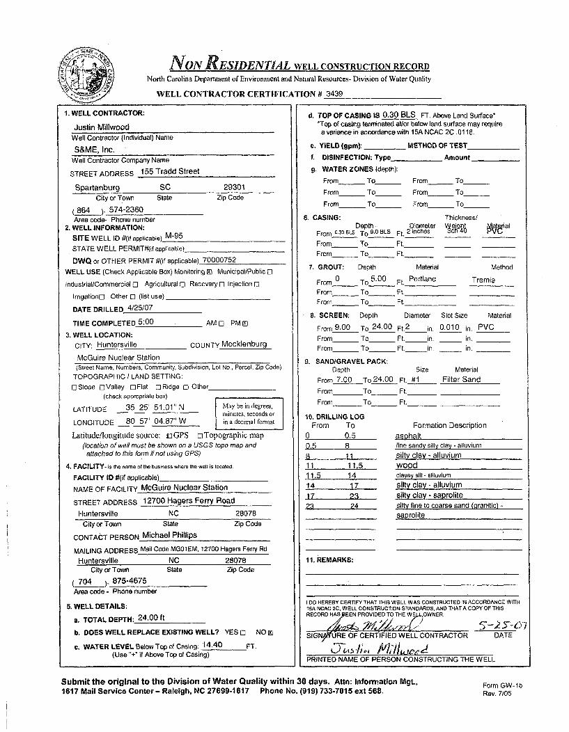
NoN RESIDENTIAL WELL CONSTRUCTION RECORD
North Carolina Department of Environment and Natural Resources- Division of Water Quality
WELL CONTRACTOR CERTIFICATION # 3439
1. WELL CONTRACTOR:
Justin MillwoodWell Contractor (Individual) Name
S&ME, Inc.
Well Contractor Company Name
STREET ADDRESS 155 Tradd Street
Spartanburg SC 29301
City or Town State Zip Code
(864 )- 574-2360Area code- Phone number
2. WELL INFORMATION:
SITE WELL ID #(if applicable) M-95
STATE WELL PERMIT#(if applicable)
DWQ or OTHER PERMIT #(if applicable) 70000752
WELL USE (Check Applicable Box) Monitoring RI Municipal/Public E
Industrial/Commercial El Agricultural 0 Recovery E] Injection El
IrrigationnJ Other [] (list use)
DATE DRILLED 4/25/07
TIME COMPLETED 5:00 AM El PM El
3. WELL LOCATION:
CITY: Huntersville COUNTY Mecklenburg
McGuire Nuclear Station
d. TOP OF CASING IS 0.30 BLS FT. Above Land Surface**Top of casing terminated at/or below land surface may require
a variance in accordance with 15A NCAC 2C .0118.
e. YIELD (gpm): ,. METHOD OF TEST
1. DISINFECTION: Type_ Amount
9. WATER ZONES (depth):
From To From To
From _ To_ From - To
From To From To
6. CASING: Thickness/Depth. Diameter Myaierial
From 0.30 8LS To 9.0 BLS Ft. 2 inches
From_ To_ Ft._
From - To _ Ft._
7. GROUT: Depth Material Method
From 0 To 5.00 Ft. Portland Tremie
From - To_ Ft.From To Ft.
8. SCREEN: Depth Diameter Slot Size Material
From 9.00 To 24.00 Ft. 2 in. 0.010 in. PVCFrom _ To _____Ft. in, in.
From _ To _ Ft. in. _ in.
9. SAND/GRAVEL PACK:
Depth Size Material
From 7.00 To 24.00 Ft, #1 Filter Sand
From To Ft.
From To Ft._
10, DRILLING LOGFrom To Formation Description
0 0.5 asohalt
0.5 8 fine sandy silty clay - alluvium
8 11 .silty clay - alluvium11 11.5 wood11.5 14 clayey silt- allluvium
14 17 silty clay - alluvium17 23 silty clay - saprolite23 24 silty fine to coarse sand (.granitic) -
saprolite
11. REMARKS:
(Street Name, Numbers, Community, Subdivision, Lot No., Parcel, Zip Code)
TOPOGRAPHIC / LAND SETTING:
ElSIope ElValley OFIat ElRidge El Other(check appropriate box)
LATITUDE 35 25' 51.01" N May be in degrees,ninntes, seconds or
LONGITUDE 80 57' 04.87" W in a decimal format
Latitude/longitude source: uGPS ElTopographic map(location of well must be shown on a USGS topo map and
attached to this form if not using GPS)
4. FACILITY- is the name of the business where the well is located.
FACILITY ID #(if applicable)_
NAME OF FACILITY McGuire Nuclear Station
STREET ADDRESS 12700 Hagers Ferry Road
Huntersville NC 28078
City or Town State Zip Code
CONTACT PERSON Michael Phillips
MAILING ADDRESS Mail Code MG01EM, 12700 Hagers Ferry Rd
Huntersville NC 28078
City or Town State Zip Code
704 ) 875-4675Area code - Phone number
5. WELL DETAILS:
a. TOTAL DEPTH: 24.00 ft
b. DOES WELL REPLACE EXISTING WELL? YES El
c. WATER LEVEL Below Top of Casing: 14.40 FT.(Use "+" if Above Top of Casing)
I DO HEREBY CERTIFY THAT THIS WELL WAS CONSTRUCTED IN ACCORDANCE WITH15A NCAC 2C, WELL CONSTRUCTION STANDARDS, AND THAT A COPY OF THISRECORD HAS EEN PROVIDED TO THE WE OWNER.
NO g] SIGNp•riURE OF CERTIFIED WELL CONTRACTOR DATE
PRINTED NAME OF PERSON CONSTRUCTING THE WELL
Submit the original to the Division of Water Quality within 30 days. Attn: Information Mgt.,1617 Mail Service Center- Raleigh, NC 27699-1617 Phone No. (919) 733-7015 ext 568.
Form GW-1bRev. 7/05

NoN ORESIDENTIAL WELL CONSTRUCTION RECORDNorth Carolina Department of Environment and Natural Resources- Division of Water Quality
WELL CONTRACTOR CERTIFICATION # 3439
1. WELL CONTRACTOR:
Justin MillwoodWell Contractor (Individual) Name
S&ME, Inc.Well Contractor Company Name
STREET ADDRESS 155 Tradd Street
Spartanburg SC 29301
City or Town State Zip Code
(864 ). 574-2360
Area code- Phone number2. WELL INFORMATION:
SITE WELL ID #(if applicable) M-95R
STATE WELL PERMIT#(if applicable)_
OWO or OTHER PERMIT #(if applicable) 70000752
WELL USE (Check Applicable Box) Monitoring m Municipal/Public 12
Industrial/Commercial 0 Agricultural C1 Recovery C3 Injection 0
Irrigation[] Other El (list use)
DATE DRILLED 4/24/07
TIME COMPLETED,5: 0 0 AM 0 PM El
3. WELL LOCATION:
CITY: Huntersville COUNTY Mecklenburg
McGuire Nuclear Station(Street Name, Numbers, Community, Subdivision, Lot No., Parcel, Zip Code)
TOPOGRAPHIC / LAND SETTING:
0 Slope [I Valley E] Flat 0 Ridge 0 Other(check appropriate box)
LATITUDE 35 25' 51.00" N May be in degrees,minutes, seconds or
LONGITUDE 80 57' 04.81" W in a decimal format
Latitude/longitude source: ujGPS orTopographic map(location of well must be shown on a USGS topo map andattached to this form if not using GPS)
4. FACILITY- is the name of the business where the well is located.
FACILITY ID #(if applicable)
NAME OF FACILITY McGuire Nuclear Station
STREET ADDRESS 12700 Hagers Ferry Road
Huntersville NC 28078
d. TOP OF CASING IS 0.16 BLS FT. Above Land Surface**Top of casing terminated atlor below land surface may requirea variance in accordance with 15A NCAC 2C .0118.
e. YIELD (gpm): METHOD OF TEST
I. DISINFECTION: Type Amount
g. WATER ZONES (depth):
From- . To_ From_ To
From_ To_ .- From_ To
From - To_ From_ To
6. CASING: Thickness/Depth Diameter We Mah6 teial
From o•e6BLS TO 39.0BLS Ft. 2 inches 5CP4
From_ To_ Ft._
From To _ Ft._
7. GROUT: Depth Material Method
From 0 To 20.00 Ft. Portland Tremie
From_ To_ Ft.
From_ To_ Ft.
8. SCREEN: Depth Diameter Slot Size Material
From 39.00 To 44.00 Fl.2 in. 0.010 in. PVCFrom To _ Ft. in. in.
From_ To_ Ft. in. in.
9. SAND/GRAVEL PACK:Depth Size Material
From 44 To 45 Ft. #2 Filter Sand
From To_ Ft._
From To_ Ft._
10. DRILLING LOGFrom To Formation Description
0 0.50.5 8
8 1111 11.511.5 1414 1717 2323 27
27 32
32 36.536.5 64.5
11. REMARKS:
asohaltline sandy silty cay - alluvium
silty clay - alluviumwoodclayey sit -ailluvium
silty clav - alluviumsilty clay - saprolitesilty tine tn onarse sand tnmnitic.~ os mit fine . ... ... to coars...n Ina icisaprolite
City or Town State Zip Code
CONTACT PERSON Michael Phillips
MAILING ADDRESS Mail Code MG01 EM, 12700 Hagers Ferry Rd
Huntersville NC 28078
fine to med sandy silt (schistose) - saprolite
silty line sand (granitic) - saprolite -med to coarse granite and quartz diorite
City or Town State
(704 ). 875-4675Area code - Phone number
Zip Code - bentonite placed below well from 45 to 64.5 ft BLS
- K-eacker Dlaced at 36.8 to 38.3 ft BLS: bentonite seal placed
5. WELL DETAILS:
a. TOTAL DEPTH: 44.00 it
b. DOES WELL REPLACE EXISTING WELL? YES 0 NO OD
c. WATER LEVEL Below Top of Casing: 14.54 FT.(Use "+" if Above Top of Casing)
at 20 to 36.8 it BLS; no sand/gravel pack below K-packerI D0 HEREBY CERTIFY THAT THIS WELL WAS CONSTRUCTED IN ACCORDANCE WITI15A NCAC 29, WELL CONSTRUCTION STANDARDS, AND THAT A COPY OF THISRECORD EEN PROV DEQ TOTHE WAl WNER,
SIG9A'TURE OF CERTIFIED WELL CONTRACTOR DATE
PRINTED NAME OF PERSON CONSTRUCTING THE WELL
Submit the original to the Division of Water Quality within 30 days. Attn: Information Mgt.,1617 Mail Service Center- Raleigh, NC 27699-1617 Phone No. (919) 733-7015 ext 568.
Form GW-ibRev. 7/05

NON ARESIDENTIAL WELL CONSTRUCTION RECORD
North Carolina Department of Environment and Natural Resources- Division of Water Quality
WELL CONTRACTOR CERTIFICATION # 3439
1. WELL CONTRACTOR:
Justin MillwoodWell Contractor (Individual) Name
S&ME, Inc.Well Contractor Company Name
STREET ADDRESS 155 Tradd Street
Spartanburg SC 29301City or Town State Zip Code
* (864 )- 574-2360Area code- Phone number
2. WELL INFORMATION:
SITE WELL ID #(if applicable) M-96
STATE WELL PERMIT#(it applicable)
DWQ or OTHER PERMIT #(if applicable) 70000752
WELL USE (Check Applicable Box) Monitoring m1 Municipal/Public C3
Industrial/Commercial 0 Agricultural El Recovery D Injection El
Irrigationc Other [I (list use).
DATE DRILLED 5/4/07
TIME COMPLETED 5:00 AM El PM m
3. WELL LOCATION:
CITY: Huntersville COUNTY Mecklenburg
McGuire Nuclear Station(Street Name, Numbers, Community, Subdivision, Lot No., Parcel, Zip Code)
TOPOGRAPHIC / LAND SETTING:
ElSIope oValley 0FIat ELRidge El Other(check appropriate box)
LATITUDE 35 25' 52.96" N May be in degrees,minutes, seconds or
LONGITUDE 80 56' 59.27" W in a decimal format
Latitude/longitude source: UGPS El Topographic map(location of well must be shown on a USGS topo map andattached to this form if not using GPS)
4. FACILITY- is the name of the business where the well is located,
FACILITY ID #(if applicable)
NAME OF FACILITY McGuire Nuclear Station
STREET ADDRESS 12700 Hagers Ferry Road
Huntersville NC 28078City or Town State Zip Code
CONTACT PERSON Michael Phillips
MAILING ADDRESS Mail Code MG01EM, 12700 Hagers Ferry Rd
Hiimto.rqvill. NC P8078
d. TOP OF CASING IS 2.98 FT. Above Land Surface-*Top of casing terminated at/or below land surface may require
a variance in accordance with 15A NCAC 2C .0118.
e. YIELD (gpm): METHOD OF TEST
f. DISINFECTION: Type _ Amount
g. WATER ZONES (depth):
From To From To
From_ To_ _ From_ To_ _
From - To_ From_ To
6. CASING: Thickness/Depth Diameter Mgh Paterial
From 2.96ALS To 19.OOLS Ft. 2 inches VeFrom_ To_ Ft._
From - To_ Ft._
7. GROUT: Depth Material Method
From 0 To 15.00 Ft. Portland Tremie
From To Ft
From _ To Ft.
a. SCREEN: Depth Diameter Slot Size Material
From 19.00 To 34.00 Ft.2 in. 0.010 in. PVCFrom_ To Ft. in. in.
From_ To Ft. in, _ in.
9. SANDIGRAVEL PACK:Depth Size Material
From 17.00 To3 4
.00 Ft. #1 Filter SandFrom To_ Ft._
From To_ Ft._
10, DRILLING LOGFrom To Formation Description
0 8 fine sandy clayey silt - fill8 12 fine sandy clayey silt - saprolite12 34 slightly clayey fine sandy silt -
_saprolite
11. REMARKS:City or Town State
704 ) 875-4675Area code - Phone number
Zip Code
5. WELL DETAILS:
a. TOTAL DEPTH: 34.00 ft
b. DOES WELL REPLACE EXISTING WELL? YES El NO 91
c. WATER LEVEL Below Top of Casing: 26.73 FT.(Use "+" if Above Top of Casing)
I DO HEREBY CERTIFY THAT THIS WELL WAS CONSTRUCTED IN ACCORDANCE WITH15A NCAC 2C.• ELL CONSTRUCTION STANDARDS, AND THAT A COPY OF THISRECORD HIABEEN PROVIDED TO THE WELL •INER.
SIG- 'URE OF CERTIPIIED WELL CONTRACTOR DATE
JTT /i,; A'7,' /I L:L.'i,
PRINTED NAME OF PERSON CONSTRUCTING THE WELL
Submit the original to the Division of Water Quality within 30 days. Attn: Information Mgt.,1617 Mail Service Center - Raleigh, NC 27699-1617 Phone No. (919) 733-7015 ext 568.
Form GW-lbRev. 7/05

NON RESIDENTIAL WELL CONSTRUCTION RECORDNorth Carolina Department of Environment and Natural Resources- Division of Water Quality
WELL CONTRACTOR CERTIFICATION # 3439
8. TOP OF CASING IS 2.85 FT. Above Land Surf ace"1. WELL CONTRACTOR:
Justin MillwoodWell Contractor (Individual) Name
S&ME, Inc.Well Contractor Company Name
STREET ADDRESS 155 Tradd Street
Spartanburg SC 29301City or Town State Zip Code
(864 )- 574-2360Area code- Phone number
2. WELL INFORMATION:
SITE WELL ID #(if applicable) M-96R
STATE WELL PERMIT#(If applicable)
DWQ or OTHER PERMIT #(if applicable) 70000752WELL USE (Check Applicable Box) Monitoring M Municipal/Public E0
Industrial/Commercial 0 Agricultural 0 Recovery 0 Injection 0
Irrigationo Other C (list use)
DATE DRILLED 4/26/07
TIME COMPLETED 5:00 AM -] PM Ei3. WELL LOCATION:
CITY: Huntersville COUNTY Mecklenburg
McGuire Nuclear Station(Street Name, Numbers, Community, Subdivision, Lot No., Parcel, Zip Code)
TOPOGRAPHIC / LAND SETTING:E Slope 0 Valley - Flat 0 Ridge 0 Other
(check appropriate box)
LATITUDE 35 25' 52.97" N May be in degrees,minusLes, seconds or
LONGITUDE 80 56' 59.33" W is a decimal format
Latitude/longi.tude source: o GPS oTopographic map(location of well must be shown on a USGS topo map andattached to this form if not using GPS)
4. FACILITY- is the name of the business where the well is located.
FACILITY ID #(if applicable)_
NAME OF FACILITY McGuire Nuclear Station
STREET ADDRESS 12700 Hagers Ferry Road
Huntersville NC 28078City or Town State Zip Code
CONTACT PERSON Michael Phillips
MAILING ADDRESS Mail Code MG01EM, 12700 Hagers Ferry Rd
Huntersville NC 28078City or Town State Zip Code
704__ ).875-4675Area code - Phone number
5. WELL DETAILS:
a. TOTAL DEPTH: 87.00 ft
b. DOES WELL REPLACE EXISTING WELL? YES 0 NO 91
c. WATER LEVEL Below Top of Casing: 26.6 FT.(Use "+" if Above Top of Casing)
d. TOP OF CASING is 2.85 FT. Above Land Surface-*Top of casing terminated at/or below land surface may require
a variance in accordance with 15A NCAC 2C .0118.
e. YIELD (gpm): METHOD OF TEST
f. DISINFECTION: Type_ Amount
g. WATER ZONES (depth):
From To From To
From To From To
From_ To_ From_ To
6. CASING: Thickness/Depth Diameter Veight ateial
From 2.8,ALS To82.0BLS Ft. 2 inches h4
From_ To - Ft._
From_ To_ Ft._
7. GROUT: Depth Material Method
From 0 To 78.00 Ft. Portland Tremie
From To Ft.
From_ To Ft.
8. SCREEN: Depth Diameter Slot Size Material
From 82.00 To 87.00 Ft. 2 in. 0.010 in, PVCFrom To Ft. in. in.
From To_ _ Ft. in. in.
9. SAND/GRAVEL PACK:Depth Size Material
From 87 To 88.00 Ft. #2 Filter Sand
F rom To Ft._
From To_ Ft._
10. DRILLING LOGFrom To Formation Description
0 8 fine sandy clayey silt - fill8 12 fine sandy clayey silt - saprolite
12 47 slightly clayey fine sandy silt -saprolite
47 52.5 silty fine to med sand - saprolite52.5 80 silty fine to coarse sand (granitic) -
weathered rock
80 99.57 fine to coarse grained quartz diorite
11. REMARKS:- bentonite placed below well from 88 to 99.57 ft BLS
- K-packer placed at 79.8 to 81.3 ft BLS; bentonite seal placed at
78 to 79.8 ft BLS; no sand/gravel pack below K-packerI DO HEREBY CERTIFY THAT THIS WELL WAS CONSTRUCTED IN ACCORDANCE WITH15A NCAC 20, WE.t.L CONSTRUCTION STANDARDS, AND THAT A COPY OF THISRECORD HAS SI N PROVOIED ToC'ETh WELL 7 1WNR.
I , L4 "ý"; -2 S' -e 7SIGNA)iRE OF CERTII~lED WELL CONTRACTOR DATE
PRINTED NAME OF PERSON CONSTRUCTING THE WELL
Submit the original to the Division of Water Quality within 30 days. Attn: Information Mgt.,1617 Mail Service Center- Raleigh, NC 27699-1617 Phone No. (919) 733-7015 ext 568. Form GW-lb
Rev. 7/05

NON RESIDENTIAL WELL CONSTRUCTION RECORDNorth Carolina Department of Environment and Natural Resources- Division of Water Quality
WELL CONTRACTOR CERTIFICATION # 3439
1. WELL CONTRACTOR:
Justin MillwoodWell Contractor (Individual) Name
S&ME, Inc.Well Contractor Company Name
STREET ADDRESS 155 Tradd Street
Spartanburg SC 29301
City or Town State Zip Code
(864 )- 574-2360Area code- Phone number
2. WELL INFORMATION:SITE WELL ID 4(if applicable) M-97
STATE WELL PERMIT#(If applicable)_
DWQ or OTHER PERMIT #(if applicable) 70000752
WELL USE (Check Applicable Box) Monitoring El Municipal/Public 0
Industrial/Commercial 0 Agricultural [ Recovery E] Injection El
Irrigationo] Other El (list use)
DATE DRILLED 5/8/07
TIME COMPLETED 5:00 AM : PM Ei
3. WELL LOCATION:
CITY: Huntersville COUNTY Mecklenburg
McGuire Nuclear Station
(Street Name, Numbers, Community, Subdivision, Lot No., Parcel, Zip Code)TOPOGRAPHIC / LAND SETTING:
DSIope OValley ELFlat E31Ridge [U Other
(check appropriate box)
LATITUDE 35 25' 51.65" N May be in degrees,minutes, seconds or
LONGITUDE 80 56' 51.19" W in a decimal format
Latitude/longitude source: uGPS l]Topographic map(location of well must be shown on a USGS topo map andattached to this form if not using GPS)
4. FACILITY- is the name of the business where the well is located.
FACILITY ID 4(if applicable)
NAME OF FACILITY McGuire Nuclear Station
STREET ADDRESS 12700 Hagers Ferry Road
Huntersville NC 28078City or Town State Zip Code
CONTACT PERSON Michael Phillips
MAILING ADDRESS Mail Code MG01EM, 12700 Hagers Ferry Rd
Huntersville NC 28078City or Town State Zip Code
704 )- 875-4675Area code - Phone number
5. WELL DETAILS:
a. TOTAL DEPTH: 26.00 ft
b. DOES WELL REPLACE EXISTING WELL? YES 0 NO E
c. WATER LEVEL Below Top of Casing: 12.70 FT.(Use "+" if Above Top of Casing)
d. TOP OF CASING IS 0.34 BLS FT. Above Land Surface*'Top of casing terminated at/or below land surface may require
a variance in accordance with 15A NCAC 2C .0118.
e. YIELD (gpm): METHOD OF TEST
1. DISINFECTION: Type __ Amount
8. WATER ZONES (depth):
From _ To _ From_ To
From _ To From_ To___
From_ To_ From_ To
6. CASING: Thickness/Depth Diameter leiht, Material
From 0.34 BLS To 11.o BLS Ft. 2 inches c Pvc
From_ To_ Ft._ _
From_ To_ Ft. _ _
7. GROUT: Depth Material Method
From 0.54 To 5.00 Ft. Portland Tremie
From To Ft.
From_ To_ Ft.
8. SCREEN: Depth Diameter Slot Size Material
From 11.00 To 26.00 Ft.2 in. 0.010 in. PVCFrom _ To _ Ft. in. _ _in.
From _ To Ft. in. i tn.
9. SANDIGRAVEL PACK:
Depth Size Material
From 9.00 To 27.50 Ft. #2 Filter Sand
From To_ Ft._
From _ To Ft._
10. DRILLING LOGFrom To Formation Description
0 0.5 asphalt over gravel0.5 13.5 sligthtly clayey silt - saprolite13.5 22 silt - saprolite22 42 slightly clayey silty sand - saprolite42 51.9 slightly clayey sandy silt - saprolite
51.9 refusal to roller cone drill bit51 P 9q 40 fine to medium grained diorite/
q uartz diorite
11. REMARKS:bentonite placed below sand pack from 27.5 ft to 99.40 ft
I DO HEREBY CERTIFY THAT THIS WELL WAS CONSTRUCTED IN ACCORDANCE WITH15A NCAC 2W, WELL CONSTRUCTION STANOARD , AND THAT A COPY OF THISRECORD H... BEEN PROVIDED TO H WEL 'ONER.
SIC(ATURE OF CERTIFUED WELL CONTRACTOR DATE
PRINTED NAME OF PERSON CONSTRUCTING THE WELL
Submit the original to the Division of Water Quality within 30 days. Attn: Information Mgt.,1617 Mail Service Center- Raleigh, NC 27699-1617 Phone No. (919) 733-7015 ext 568.
Form GW-lbRev. 7/05

iVON RESIDENTIAL WELL CONSTRUCTION RECORD
North Carolina Department of Environment and Natural Resources- Division of Water Quality
WELL CONTRACTOR CERTIFICATION # 2717
1. WELL CONTRACTOR:
Jay LittleWell Contractor (Individual) Name
S&ME, Inc,Well Contractor Company Name
STREET ADDRESS 9751 Southern Pine Boulevard
Charlotte NC 28273City or Town State Zip Code
)704 . 523-4726Area code- Phone number
2. WELL INFORMATION:
SITE WELL ID #(it appliceblel M-98
STATE WELL PERMIT#lif applicable)_
DWQ or OTHER PERMIT #(If applicable) 70000752
WELL USE (Check Applicable Box) Monitoring 0 Municipal/Public C]
Industrial/Commercial 0 Agricultural 0 Recovery 0 Injection E3
Irrigationo Other 0 (list use)
DATE DRILLED 5/2/07.
TIME COMPLETED 5:00 AM o PM pI
3. WELL LOCATION:
CITY: Hunteraville COUNTY Mecklenburg
McGuire Nuclear Station
d. TOP OF CASING IS 2.89 FT. Above Land Surface*'Top of casing terminated at/or below land surface may requirea variance In accordance with 1,A NCAC 2C .0118.
a. YIELD (gpm) _... METHOD OF TEST
f. DISINFECTION: Type Amount
g. WATER ZONES (depth):
From_ To_ From_ To__
Frornm To_ From_ To
From_ To_ From_ To___
6. CASING: Thickness/Depth Diameter
From 2.s8 ALS To 12.OBLS Ft. 2 inches ch 4il
From_ To Ft. _
From_ To_ Ft. _ _
7. GROUT: Depth Material Method
From_0 To_7.00 Ft. Portland Tremie
From__ Tc__ Ft._
From_ To_ Ft.
B. SCREEN: Depth Diameter Slot Size Material
From 12.00 To._27.00 Ft.2
In. 0.010 In, PVCFrom_ To_ Ft. In. In,From__ To__ Ft. in. - In,
9. SAND/GRAVEL PACK.Depth Size Matedal
From 9.00 To 27.00 Ft, #1 Filter Sand
From To _ Ft.
From To._ Ft._
10. DRILLING LOGFronm To Formation Description
0 4.25 fine to med sandy silt - saprolite
4 29 8 ,slty fine to ted sand - saprolite
8 13 fine sandy slit - saprollte
13 20 silty fine to med sand - saprolite20 2075 silly fine to ted sand - weathered rock20.75 28 medium grained quartz diorite/,ranite -
sound rock
11. REMARKS:
(Street Name, Numbers, Community, Subdivision, Lot No.. Parcel. Zip Code)TOPOGRAPHIC I LAND SE1TING:0 SIope oValley OFlat VRidge ED Other
(check appropriate box)LATITUDE 35_25' 48,07" N May be in degrees,
minnutes, seconds or
LONGITUDE 80_56' 58.06"W ina decimal lbnnlal
Latitude/Iongitude source: uOPS DTopographic map(location of well must be shown on a USGS topo map andattached to this form if not using GPS)
4. FACILITY. is the name of the business where the well Is located.
FACILITY ID #(If applicable)
NAME OF FACILITY McGuire Nuclear Station
STREET ADDRESS 12700 Hagers Ferry Road
Huntersville NC 28078City or Town State Zip Code
CONTACT PERSON Michael Phillips
MAILING ADDRESS Mall Code MGOOEM. 12700 Hagers Ferry Rd
Huntersville NC 28078City or Town State Zip Code
704 ). 875-4675Area code - Phone number
5. WELL DETAILS:
a. TOTAL DEPTH: 27.00 ft
b. DOES WELL REPLACE EXISTING WELL? YES D NO at
c. WATER LEVEL Below Top of Casing: 16.39 FT.(Use "+" If Above Top of Casing)
I 00 HEREBY CERTIFY THAT THIS WELL WAS CONSTRUCTED IN ACCORDANCE WnIh15A NCAC 2C, WELL CONSTRUCTION STANDARDS. AND THAT A COPY OF THISRECORDFI-EIAEEN PROVIDED TOTHE WELL OWNER.
,51GNtA-T.RE OF CERTIFIED WELL CONTRACTOR DATEI,,/ N
PRINTE 6NAME OF PERSON CONSTRUCTING THE WE'LL
Submit the original to the Division of Water Quality within 30 days. Attn: Information Mgt.,1617 Mail Service Center - Raleigh, NC 27699-1617 Phone No, (919) 733-7015 ext 568,
Form GW-lbRev. 7105

ATON RESIDENTIAL WELL CONSTRUCTION RECORDNorth Carolina Department ofEnvironment a-d Natural Resources- Division of Water Quality
WELL CONTRACTOR CERTIFICATION # 2717
'1. WELL CONTRACTOR:
Jay LittleWell Contractor (Individual) Name
S&ME, Inc.Well Contractor Company Name
STREET ADDRESS 9751 Southern Pine Boulevard
Charlotte NC 28273
City or Town State Zip Code
(704 ). 523-4726Area code- Phone number
2. WELL INFORMATION:
SITE WELL ID #(If applicable) M-98R
STATE WELL PERMIT#(If applicabte).
DWQ or OTHER PERMIT #(If applicable) 70000752
WELL USE (Check Applicable Box) Monitoring ER Municipal/Public D
Industrlal/Commercial D Agricultural E] Recovery C Injection 0
Irrigatlon(] Other 0 (list use)
DATE DRILLED 4/25107
TIME COMPLETED 5:00 AM D PM5J
3. WELL LOCATION:
CITY: Huntersville COUNTY Mecklenburg
McGuire Nuclear Station
d. TOP OF CASING IS 3.22 FT. Above Land Surface-'Top of casing terminated at/or below land surface may require
a variance In accordance with 15A NCAC 2C .0118.
e. YIELD (gpm): _ METHOD OF TEST
fL DISINFECTION: Type________ Amount
g. WATER ZONES (depth):
From__ To From_ To_
From_ To_ From _ Tlo_
From_ To From_ To
6. CASING: Thickness/Depth Diameter Jeg( /trlal
From ,22 11-s To _ 26 eL8 Ft. 2 Incheter._ 4
From To _ Ft._
From_ To_ Ft -
7. GROUT: Depth Material Method
From 0 To 40.80 Ft. Portland Tremie
From.._ To_ Ft.From___ To_ Ft.
0, SCREEN: Depth Diameter Slot Size Material
From 42.60 To 47.60 Ft.2 in. 0.010 In. PVC
From__ _ To Ft. In. In.
From_ To Ft. in. _ in.
g. SAND/GRAVEL PACK:Depth Size Material
From 47.60 To4 8 .
6 0 Ft. #1 Filter Sand
From To_ Ft._
From To__ Ft.
10, DRILLING LOGFrom To Formation Description
n 42 95 fin, +n mol crnHnrill. en rnlif
(Street Name, Numbers, Community, Subdivision, Lot No., Parcel, Zip Code)TOPOGRAPHIC I LAND SETTING:
]Slope oValley OFlat £Ridge 0 Other(check appropriate box)
LATITUDE 35_25' 48.12" N May be in degrees,minutes, seconds or
LONGITUDE 80 56' 58.10"W in a decimsaltbmat
Latitude/longitudesource: ;UGPS oTopographic map(location of well must be shown on a USGS topo map endattached to this form it not using GPS)
4, FACILITY-1is the naee of e auelness where tle well Is localed.
FACILITY ID #(if applicable)_
NAME OF FACILITY McGuire Nuclear Station
STREET ADDRESS 12700 Hagers Ferry Road
Hunteraville NC 28078
4 25 L
19 1313 2020 409520.75 49.7
silty fine to med sand - sagrolite
fine sandy silt - saprolitesilty fine to med sand - saorolitesilty fine to mad sand - weathered rockmedium grained quartz diorlte/granite -sound rockCity or Town State Zip Code
CONTACT PERSON Michael Phillips
MAILING ADDRESS Mall Code MG01EM, 12700 Hagers Ferry RdHuntersvitle NC 28078
City or Town State Zip Code
704 . . 875-4675Area code - Phone number
5. WELL DETAILS:
a. TOTAL DEPTH: 47.60 ft
b. DOES WELL REPLACE EXISTING WELL? YES 0 NO 9
c. WATER LEVEL BelowTop of Casing: 19.52 FT.(Use "" if Above Top of Casing)
11. REMARKS:- K-packer placed at 41.65 to 41.9 ft BLS; bentonite seal placedat 40.8 to 41.65 ft BLS- bentonite placed below well from 48.6 to 49.7 ft BLSI DO HEREBY CERTIFY THAT'THIS WELL WAS CONSTRUCTED IN ACCORDANCE WITH15A NCAC 2C, WELL CONSTRUCTION STANDARDS, AND THAT A COPY OF THISRECORDHSEEN PROVIDED TO THE WELL OWNER.
o'fr'GN,4.E OF CERTIFIED WELL CONTRACTOR DATE
PRINTED NAME OF PERSON CONSTRUCTING THE WELL
Submit the original to the Division of Water Quality within 30 days. Attn: Information Mgt.,1617 Mail Service Center - Raleigh, NC 27699-1617 Phone No. (919) 733-7015 ext 568.
Form GW-lbRev. 7/05

NONJRESIDENTIAL WELL CONSTRUCTION RECORDNorth Carolina Department of Environment and Natural Resources- Division of Water Quality
WELL CONTRACTOR CERTIFICATION # 2717
1. WELL CONTRACTOR:
Jay Little
Well Contractor (Individual) Name
S&ME, Inc.Well Contractor Company Name
STREET ADDRESS 9751 Southern Pine Boulevard
Charlotte NC 28273City or Town State Zip Code
(704 ). 523-4726Area code- Phone number
2. WELL INFORMATION:SITE WELL ID I(if applicable) M-100RSTATE WELL PERMIT#(if applicable)
DWQ or OTHER PERMIT #(if applicable) 70000752WELL USE (Check Applicable Box) Monitoring RI Municipal/Public 0
IndustrlailCommercial 0 Agricultural [-0 Recovery 0i Injection 0]
Irrigationo Other 0 (list use)
DATE DRILLED 4/24/07
TIME COMPLETED 5:00 AMO PMEI
3. WELL LOCATION;
CITY: Huntersville COUNTY Mecklenburg
McGuire Nuclear Station
d. TOP OF CASING IS 2.96 FT. Above Land Surface'*Top of Casing terminated al/or below land surface may require
a variance In accordance with 15A NCAC 2C 0118.
e. YIELD (gpm): METHOD OF TEST _1. DISINFECTION: Type_ Amount ..........
g. WATER ZONES (depth):
From- To From_ To
From To From_ To
From_ To _ From_ To_
6. CASING: Thickness/Depth Diameter VWighs a rial
FromSas A~a Tol.0 BLS Ft. 2 inches _ c 4O
From_ To_ Ft.__
From_ To__ Ft__ _
7. GROUT: Depth Material MethodFrom 0 To 30.00 Ft. Portland Tremie
From _ To__ Ft.
From___ To _ Ft.
8. SCREEN: Depth Diameter Slot Size Material
From 42.00 To 47.00 Ft.2
in. 0.010 in. PVCFrom_ To_ Ft, In. - In.
From _ To _ Ft. in. in.
9. SANDIGRAVEL PACK:Depth Size Material
From 47.00 To 50,00 Ft. #1 Filter Sand
From To_ Ft._
From To_ Ft.
10. DRILLING LOGFrom To Formation Description
0 0.5 gravel
05 30 sandy silty clay
30 40.25 fine to coarse sand - weatheredrock (granitic)
40.25 60.0 fine grained granite - sound rock
11. REMARKS:
- K-packer placed at 41.25 to 41.5 ft BLS; bentonite seal placed
at 30.0 to 41.25 ft BLS
(Street Name, Numbers, Community, Subdivision, Lot No., Parcel, Zip Code)TOPOGRAPHIC / LAND SETTING:
DSlope [DValley []Flat 13RIdge 0 Other(check appropriate box)
LATITUDE 35 25' 47.38" N May be in degrees,i'inut.s, seconds or
LONGITUDE 80 57' 07.53"W in it decimal format
Latitude/longitudesource: uGPS rcTopographic mapl(location of well must be shown on a USGS topo map and
attached to this form if not using GPS)
4. FACILITY- Is the name of the business where the well is socaled.
FACILITY ID #(if applicable)
NAME OF FACILITY MoGuire Nuclear Station
STREET ADDRESS 12700 Hagers Ferry Road
Huntersville NC 28078City or Town State Zip Code
CONTACT PERSON Michael Phillips
MAILING ADDRESS Mall Code MG01EM, 12700 Hegers Ferry Rd
Huntersville NC 28078City or Town State Zip Code
704 ). 875-4675Area code. Phone number
6. WELL DETAILS:
a. TOTAL DEPTH: 47.00 ft
b. DOES WELL REPLACE EXISTING WELL? YES 0 NO W
c. WATER LEVEL Below Top of Casing: 31,38 FT.(Use "+" If Above Top of Casino)
- bentonite placed below well from 50.0 to 60.0 ft BLSI DO HEREBY CERTIFY THAT THIS WELL WAS CONSTRUCTED IN ACCORDANCE WITHlEA NCAC 2C, WELL CONSIRUCTION STANDARDS, AND THAT A COPY OF THISRECORDS•Ep as EN PROVIDED TO THE WELL OWNER.
,'S" G•ffURE OF CERTIFIED WELL CONTRACTOR DATE
d
PRINTEO NAME OF PERSON CONSTRUCTING THE WELL
Submit the original to the Division of Water Quality within 30 days. Attn: Information Mgt,,1617 Mail Service Center - Raleigh, NC 27699-1617 Phone No. (919) 733-7015 ext 568.
Form GW-lbRev. 7105

July 3 1, 2007
Mecklenburg County Health DepartmentLand Use & Environmental Service AgencyGroundwater & Wastewater Services700 North Tryon Street, Suite 211Charlotte, North Carolina 28202
Reference: NON-RESIDENTIAL WELL CONSTRUCTION RECORDS - SUBMITTAL #3McGUIRE NUCLEAR STATION12700 Hagers Ferry RoadHuntersville, North CarolinaWell Application Permit No. 70000752S&ME Project No. 1264-06-724
Ladies and Gentlemen:
On behalf of Duke Energy, S&ME, Inc. (S&ME) is submitting the enclosed Monitor Well Registrationform and completed/signed Non-Residential Well Construction Records for the following six (6)groundwater monitoring wells installed at the McGuire Nuclear Station (MNS) site:
* M-30 • M-33• M-30R • M-34DR* M-32 . M-34R.
Duke Energy is voluntarily installing groundwater monitoring wells at MNS as part of a site-widehydrogeologic evaluation. S&ME will submit these Non-Residential Well Construction Records on aperiodic basis as well installations are completed, this being the third submittal (i.e., Submittal #3).
On behalf of Duke Energy, S&ME thanks you for your receipt of these records. Should you have anyquestions or need additional information, please contact us.
Sincerely,S&ME, Inc.
Mary Beth Cline, E.I.T.
Staff Professional
enclosures
cc: Messrs. Steve LeRoy, Ed Sullivan, Tim Hunsucker; Duke Energy /SAENVIROMN2006\J 264 Projects\6406724 McGuire Nuclear Groundwater StudyWCDENR Well Records.neck co well records submittal 3.doc
S&ME, INC. / 155 Tradd Street / Spartanburg, SC 29301 / p 864.574.2360 f 864.576.8730
1 Marcus Drive / Greenville, SC 29615 / p 864-232-8987 / www.smeinc.com

Mecklenburg CountyLand Use & Environmental Service AgencyGroundwater & Wastewater Services700 N. Tryon St., Suite 211Charlotte, NC 28202Phone: (704) 336-5103Fax: (704) 336-6894
C-
4 y -~ ~Cl ~C-' I
6','
Monitor Well Registration
Staff Use OnlyDate Received:-- ---
Is this Registration for a well or wells that existed prior to January 01, 2005?. No
Enter your Subsurface Investigation Permit #: 70000752 Date Well Installation Began: 5-03-07
Date Well Installation Complete: 5-17-07
Site/Contact Information Bill to Owner/Agent Name: . Duke Energy / Michael Phillips
Name of Site: McGuire Nuclear Station Owner/Agent Address: Mail Code MG01 EM 12700 Hagers Ferry Rd.Huntersville, NC 28078
Site Address: 12700 Haaers Ferry Road Owner/Agent Phone #: 704-875-4675704-875-4675
Site Tax Parcel ID: 00119103 Driller Certification #: 3439 & 2717
Type of Regqistration
This registration is for (check all that apply):
X Unregistered Permanent Monitor Wells El Yearly Update of Permanent Monitor Wells
El Temporary Monitor Wells
The following information must be completed for each tax parcel on which monitor wells have been installed:
On-Site Monitor Wells Tax Parcel #f Tax Parcel # Tax Parcel #
Type of Well # Present Type of Well # Present Type of Well # Present Type of Well # Present
Temporary* Temporary* Temporary* Temporary*
Permanent 6 Permanent Permanent Permanent
Sparge Sparge Sparge Sparge
Vapor Extraction Vapor Extraction Vapor Extraction Vapor Extraction
Recovery Recovery Recovery Recovery
Injection Injection Injection Injection
Vapor Monitoring Vapor Monitoring Vapor Monitoring Vapor Monitoring
Piezometer Piezometer Piezometer Piezometer
Groundwater Standard Groundwater Standard Groundwater Standard Groundwater Standard
Exceeded? Exceeded? Exceeded? Exceeded?
Tax Parcel # Tax Parcel # Tax Parcel # Tax Parcel #Type of Well # Present Type of Well # Present Type of Well # Present Type of Well # Present
Temporary* Temporary* Temporary* Temporary*
Permanent Permanent Permanent Permanent
Sparge Sparge Sparge Sparge
Vapor Extraction Vapor Extraction Vapor Extraction Vapor Extraction
Recovery Recovery Recovery Recovery
Injection Injection Injection Injection
Vapor Monitoring Vapor Monitoring Vapor Monitoring Vapor Monitoring
Piezometer Piezometer Piezometer - Piezometer
Groundwater Standard Groundwater Standard Groundwater Standard Groundwater Standard
Exceeded? Exceeded? Exceeded? Exceeded?*Selection of Temporary Well requires monitor well abandonment forms also be filed, Failure to file abandonment forms will result in the well beingconsidered permanent and cause the well owner to be billed the appropriate fee.
JLS 12/13/04 Final

NON RESIDENTIAL WELL CONSTRUCTION RECORDNorth Carolina Department of Environment and Natural Resources- Division of Water Quality
WELL CONTRACTOR CERTIFICATION # 3439
1. WELL CONTRACTOR:
Justin Millwood
Well Contractor (Individual) Name
S&ME, Inc.
Well Contractor Company Name
STREET ADDRESS 155 Tradd Street
Spartanburg SC 29301City or Town State Zip Code
(864 )- 574-2360
Area code- Phone number2. WELL INFORMATION:
SITE WELL ID #(if applicable) M-30
STATE WELL PERMIT#(if applicable)
DWQ or OTHER PERMIT #(if applicable) 70000752
WELL USE (Check Applicable Box) Monitoring 91 Municipal/Public [-
Industrial/Commercial [] Agricultural 0 Recovery [J Injection El
Irrigation[3 Other El (list use)
DATE DRILLED 5/17/07
TIME COMPLETED 5:00 AM [I PM El
3. WELL LOCATION:CITY: Huntersville COUNTY Mecklenburg
McGuire Nuclear Station
d. TOP OF CASING IS 3.04 FT, Above Land Surface**Top of casing terminated at/or below land surface may require
a variance in accordance with 15A NCAC 2C .0118.
e. YIELD (gpm): METHOD OF TEST
f. DISINFECTION: Type Amount _
g. WATER ZONES (depth):
From_ To_ From_ To
From_ To_ From_ To
From_ To _ From_ To
6. CASING: Thickness/Depth Diameter ' eght Material
From 3.04 ALS To 35.70 Ft. 2 inches cn PVC
From_ To_ Ft._
From_ To_ Ft._
7. GROUT: Depth Material Method
From 0 To 30.70 Ft.' Portland Tremie
From To Ft.
From_ To Ft.
8, SCREEN: Depth Diameter Slot Size Material
From 35.70 To 50.70 Ft. 2 in. 0.010 in. PVCFrom _ To _ Ft. in. _ in.
From_ To Ft. in. _ In.
9. SAND/GRAVEL PACK:
Depth Size Material
From 33.00 To 50.70 Ft. #1 Filter Sand
From To _ Ft._
From To_ Ft._
10. DRILLING LOGFrom To Formation Description
0 13.5 slightly sandy, clayey, silt - saprolite
13.5 22 silty fine sand - saprolite
22 27 silty medium to fine sand - saprolite27 32 slightly sandy, silt - saprolite32 42 clayey, silt - saprolite
42 47.8 slightly sandy, silt - saprolite
47.8 50.7 silty, medium to fine sand - saprolite
11. REMARKS:
(Street Name, Numbers, Community, Subdivision, Lot No., Parcel, Zip Code)
TOPOGRAPHIC / LAND SETTING:
[]Slope oValley []Flat [Ridge El Other
(check appropriate box)LATITUDE 35' 25' 38.41" N May be in degrees,
minutes, seconds or
LONGITUDE 800 57' 02.96" W in a decimnal formal
Latitude/longitude source: z GPS El Topographic map
(location of well must be shown on a USGS topo map andattached to this form if not using GPS)
4. FACILITY. is the name of the business where the well is located.
FACILITY ID #(if applicable)
NAME OF FACILITY McGuire Nuclear Station
STREET ADDRESS 12700 Hagers Ferry Road
Huntersville NC 28078
City or Town State Zip Code
CONTACT PERSON Michael Phillips
MAILING ADDRESS Mail Code-MG01EM, 12700 Hagers Ferry Road
Huntersville NC 28078
City or Town State Zip Code
(704_ ) 875-4675
Area code - Phone number
5. WELL DETAILS:
a. TOTAL DEPTH: 50.70 feet
b. DOES WELL REPLACE EXISTING WELL? YES El NO [N
c. WATER LEVEL Below Top of Casing: 45.63 FT.(Use "+" if Above Top of Casing)
I DO HEREBY CERTIFY THAT THIS WELL WAS CONSTRUCTED IN ACCORDANCE WITH15A NCACA. WELL CONSTRUCTION STAN.2..DS, AND THAT A COPY OF THIS
REODAS SEEN PROVIDED TOTH ELL'644NER. _____
SI/ATURE OF CE RTIFIED WELL CONTRACTOR DATE, -I v'f, M l,.
PRINTED NAME OF PERSON CONSTRUCTING THE WELL
Submit the original to the Division of Water Quality within 30 days. Attn: Information Mgt.,1617 Mail Service Center- Raleigh, NC 27699-1617 Phone No. (919) 733-7015 ext 568.
Form GW-lbRev. 7/05

NON NESIDENTIAL WELL CONSTRUCTION RECORDNorth Carolina Department of Environment and Natural Resources- Division of Water Quality
WELL CONTRACTOR CERTIFICATION # 3439
1. WELL CONTRACTOR:
Justin MillwoodWell Contractor (Individual) Name
S&ME, Inc.
Well Contractor Company Name
STREET ADDRESS 155 Tradd Street
Spartanburg SC 29301
City or Town State Zip Code
(864 )-_ 574-2360Area code- Phone number
2. WELL INFORMATION:
SITE WELL ID #(if applicable) M-30R
STATE WELL PERMIT#(if applicable)
DWQ or OTHER PERMIT #(if applicable) 70000752
WELL USE (Check Applicable Box) Monitoring M Municipal/Public LI
Industrial/Commercial [I Agricultural Di Recovery LI Injection Li
IrrigationD Other EI (list use)
DATE DRILLED 5/14/07
TIME COMPLETED 5:00 AM Di PM [
3. WELL LOCATION:CITY: Huntersville COUNTY Mecklenburg
McGuire Nuclear Station
d. TOP OF CASING IS 3.19 FT. Above Land Surface**Top of casing terminated at/or below land surface may require
a variance in accordance with 15A NCAC 2C .0118.
e. YIELD (gpm): METHOD OF TEST
f. DISINFECTION: Type Amount
g. WATER ZONES (depth):
From_ To_ From_ To
From_ To_ From_ To
From To From To
6. CASING: Thickness/Depth Diameter Weight Material
From 3.9ALS To 73.50 Ft. 2 inches ch4 PVC
From_ To_ Ft._
From- To_ Ft._
7. GROUT: Depth Material Method
From 0 To 70.00 Ft. Neat Cement Tremie
From To Ft.
From_ To_ Ft.
8. SCREEN: Depth Diameter Slot Size Material
From 73.50 To 78.50 Ft. 2 in. 0.010 in. PVCFrom To Ft. in. in.
From_ To_ Ft. in. in.
9. SAND/GRAVEL PACK:
Depth Size Material
From 78.50 To 80.30 Ft, #2 FilterSand
From To _ Ft._
From To Ft._
(Street Name, Numbers, Community, Subdivision, Lot No., Parcel, Zip Code)
TOPOGRAPHIC / LAND SETTING:
LiSlope LiValley •Flat DRidge E] Other(check appropriate box)
LATITUDE 35' 25' 38.43" N May be in degrees,minutes, seconds or
LONGITUDE 80'_57' 02.92" W in a decimal format
Latitude/longitude source: EiGPS D Topographic map(location of well must be shown on a USGS topo map andattached to this form if not using GPS)
4. FACILITY- is the name of the business where the well is located.
FACILITY ID #(if applicable)
NAME OF FACILITY McGuire Nuclear Station
10. DRILLING LOGFrom To
0 13.5
13.5 22
22 27
27 32
32 42
42 47.8
47.8 69.7
69.7 76.176.1 89.55
Formation Descriptionslightly sandy, clayey, silt - saprolitesilty fine sand - saprolitesilty medium to fine sand - saproliteslightly sandy, silt - saproliteclayey, silt - saprolite
slightly sandy, silt - saprolite
STREET ADDRESS 12700 Hagers Ferry Road
Huntersville NC
silty, medium to fine sand - saprolite
medium grained granite - weathered rock
medium grained quartz diorite28078
City or Town State Zip Code
CONTACT PERSON Michael Phillips
MAILING ADDRESS Mail Code MG01 EM, 12700 Hagers Ferry Road
Huntersville NC 28078 11. REMARKS:- bentonite placed below well from 80.301t0 89.55 ft BILSCity or Town State
704 875-4675
Area code - Phone number
Zip Code
- K-packer placed at 71.45 to 72.95 it BLS: bentonite seal placed at
70.00 to 71.45 feet BLS; no sand/gravel pack below K-packer.
5. WELL DETAILS:
a. TOTAL DEPTH: 78.50 feet
b. DOES WELL REPLACE EXISTING WELL? YES Di NO 2
c. WATER LEVEL Below Top of Casing: 46.07 FT.(Use "+" if Above Top of Casing)
100 HEREBY CERTIFY THAT THIS WELL WAS CONSTRUCTED IN ACCORDANCE WITH15A NCAC 2C, WELL CONSTRUCTION STANDARDS, AND THATA COPY OF THISRECORD E OF BEEN PROVIDED W _ _ELL CONRCOD
SrI TURE OF CERTIFIED WELL CONTRACTOR DA\TE
PRINTED NAME OF PERSON CONSTRUCTING THE WELL
Submit the original to the Division of Water Quality within 30 days. Attn: Information Mgt.,1617 Mail Service Center- Raleigh, NC 27699-1617 Phone No. (919) 733-7015 ext 568. Form GW-lb
Rev. 7/05

NON RESIDENTIAL WELL CONSTRUCTION RECORDNorth Carolina Department of" Environment and Natural Resources- Division of Water Quality
WELL CONTRACTOR CERTIFICATION # 2717
1. WELL CONTRACTOR:
Jay LittleWell Contractor (Individual) Name
S&ME, Inc.Well Contractor Company Name
STREET ADDRESS 9751 Southern Pine Boulevard
Charlotte NC 28273City or Town State Zip Code
(704 )- 523-4726Area code- Phone number
2. WELL INFORMATION:
SITE WELL ID #(if applicable) M-32
STATE WELL PERMIT#(if applicable)
DWQ or OTHER PERMIT #(If applicable) 70000752
WELL USE (Check Applicable Box) Monitoring Ml Municipal/Public E]
Industrial/Commercial 0l Agricultural D Recovery C] Injection 0
IrrigationO Other 0l (list use)
DATE DRILLED 05/03/07
TIME COMPLETED 5:00 AM El PM El
3. WELL LOCATION:
CITY: Huntersvllle COUNTY Mecklenburg
McGuire Nuclear Station
d. TOP OF CASING IS 2,98 FT. Above Land Surface**Top of casing terminated at/or below land surface may require
a variance in accordance with 15A NCAC 2C .0118.
a. YIELD (gpm): _ METHOD OF TEST
f, DISINFECTION: Type _ Amount
g. WATER ZONES (depth):
From_ To_ From To
From_ To_ From_ To
From_ To_ From_ To
6. CASING: Thickness/Depth Diameter Weight Mh. rial
From 2.9tALS To 40a.S eLs Ft. 2 Inches Pcn 40 PV4
From - To_ Ft, _
From To_ Ft._ _
7. GROUT: Depth Material Method
From 0 To 35.00 Ft. Neat Cement Tremle
From_ To_ Ft.From_ To_ Ft.
8. SCREEN: Depth Diameter Slot Size Material
From 40.00 To 55.00 Ft.2
In. 0.010 in. PVCFrom_ To_ Ft. in. _ In.From_ To_ Ft. in. In.
9. SAND/GRAVEL PACK:
Depth Size Material
From 37.00 To 56.00 Ft. #1 Filter Sand
From To Ft.
From To_ Ft.
10. DRILLING LOGFrom To Formation Description
0 5 fine ennriv rml•\n, cilt. esnrnlito
(Street Name. Numbers, Community, Subdivision, Lot No., Parcel, Zip CodelTOPOGRAPHIC / LAND SETTING:
ESIope ElValley lFIlat EORidge El Other(check appropriate box)
LATITUDE 35' 25' 39.25" N May be in degrees,intiutes, seconds or
LONGITUDE 80* 56' 37.39" W in a decimal format
Latitude/longitttde source: u GPS oTopographic map
(location of well must be shown on a USGS topo map andattached to this form if not using GPS)
4. FACILITY- is the name of the busIness where the weat Is located.
FACILITY ID #(if applicable)
NAME OF FACILITY McGuire Nuclear Station
STREET ADDRESS 12700 Hagers Ferry Road
Huntersville NC 28078
6 12
12 1717 23
23 42
42 47
47 5353 5s56 60.4
11, REMARKS:
silty fine sand - sapralits
clavev fine sand - saorolite
silty medium to fine sand - saprolitesilty line sand - saprolite
silty medium to fine sand - saprolite
slightly clayey silty tine sand - saprolite
slightly sandy silt - saprolite
silty coarse to fine sand - weathered rockCity or Town State Zip Code
CONTACT PERSON Michael Phillips
MAILING ADDRESS Mall Code M001 EM, 12700 Hagers Ferry Rd
Huntersville NC 28078City or Town State Zip Code
704 ). 875-4675Area code - Phone number
5. WELL DETAILS:
a. TOTAL DEPTH: 55,00 ft
b. DOES WELL REPLACE EXISTING WELL? YES El NO M]
c. WATER LEVEL Below Top of Casing: 54.09 FT.(Use "+" If Above Top of Casing)
1 00 HEREBY CERTIFY THAT THIS WELL WAS CONSTRUCTED IN ACCORDANCE WITH15A NCAC 2C, WELL CONSTRUCTION STANDARDS, AND THAT A COPY OF THISRECORD BEEN PROVID:EDTO ýTH/ELL WN
,GNt RE OF CERTIFIED-WELL CONTRACTOR DATE19..4, i//PRINTEdJ NAME OF PERSON CONSTRUCTING THE WELL
Submit the original to the Division of Water Quality within 30 days. Attn: Information Mgt.,1617 Mail Service Center - Raleigh, NC 27699-1617 Phone No. (919) 733-7015 ext 568. Form GW-lb
Rev. 7/05

NON RESIDENTIAL WELL CONSTRUCTION RECORDNorth Carolina Department of Environment and Natural Resources- Division of Water Quality
WELL CONTRACTOR CERTIFICATION # 2717
1. WELL CONTRACTOR:
Jay LittleWell Contractor (Individual) Name
S&ME, Inc.Well Contractor Company Name
STREET ADDRESS 9751 Southern Pine Boulevard
Charlotte NC 28273
City or Town State Zip Code
(704 . . 523-4726
Area code- Phone number2. WELL INFORMATION:
SITE WELL ID #(if applicable) M-33
STATE WELL PERMIT#(if applicable)
DWQ or OTHER PERMIT #(If applicable) 70000752
WELL USE (Check Applicable Box) Monitoring m Municipal/Public 0
Industrial/Commarcial 0 Agricultural 0 Recovery 0 Injection 0
IrrigationPl Other C0 (list use)
DATE DRILLED 05111/07
TIME COMPLETED 5:00 AMO PM[El
3. WELL LOCATION:
CITY: Huntersvllle COUNTY Mecklenburg
McGuire Nuclear Station
(Street Name, Numbers, Communiiy, Subdivision, Lot No., Parcel, Zip Code)
TOPOGRAPHIC / LAND SETTING:
OSlope OValley OFlat DRidge I] Other(check appropriate box)
LATITUDE 35' 25' 41.90" N May be in degrees,i inutes, seconds orLONGITUDE 80' 56' 24.34" W in a decimal rormut
Latitude/longitude source: ;oGPS DTopographic map
(location of wel/ must be shown on a USGS topo map andattached to this form if not using GPS)
4. FACILITY- is the name of [he business where the well Is lsated.
FACILITY ID #(if applicable)_
NAME OF FACILITY McGuire Nuclear Station
STREET ADDRESS 12700 Hagers Ferry Road
Fluntersvllle NC 28078
d. TOP OF CASING IS 3.05 FT. Above Land Surface**Top of casing terminated atlor below land surface may require
a variance in accordance with 15A NCAC 2C .0118,
e. YIELD (gpm): METHOD OF TEST
f. DISINFECTION: Type _ Amount
g. WATER ZONES (depth):
From To _ From To
From- To_ From_ To
From- To_ From_ To
8. CASING: Thickness/Depth Diameter Weig atial
From a.0sALS To 2o.OOBLS Ft. 2 inches ch 4
From To_ Ft._ _
From_ To_ Ft._ _
7. GROUT: Depth Material MethodFrom 0 To 19.00 Ft. Neat Cement Tremle
From To Ft.
From_ To__ Ft.
8, SCREEN: Depth Diameter Slot Size Material
From 23.00 To 38.00 Ft.2
In. 0.010 in, PVC
From To Ft. in, in.
From_ To Ft. in. in,
9. SAND/GRAVEL PACK:Depth Size Material
From 21.00 To38.0 0
Ft. #1 Filter Sand
From To Ft.
From To Ft._
10, DRILLING LOGFrom To Formation Description
0 7 silvy clay - saprolile
7 8.7 slightly clayey fine sandy slit - saprolite
8.7 9 sIlty clay - saprolite9 12 slightly clayey line sandy silt - saprolile
12 22 fine sandy sit- saprolite
22 27 clayey fine sandy silt- saprolite
27 34.4 slightly clayey fine Sandy silt- saprolite34.4 37 tine sandy silt - seaprollte
37 48.3 silty medium to fine sand - saprolite48.3 49.8 silty medium to fine sand- weathered rock
11. REMARKS:
City or Town State Zip Code
CONTACT PERSON Michael Phillips
MAILING ADDRESS Mail Code MG01EM, 12700 Hagers Ferry Rd
Huntarsville NC 28078City or Town State Zip Code
704 ). 875-4675
Area code - Phone number
5. WELL DETAILS:
a. TOTAL DEPTH: 38.00 ft
b. DOES WELL REPLACE EXISTING WELL? YES 0 NO Mt
c. WATER LEVEL Below top of Casing: 30.57 FT.(Use "+" if Above Top of Casing)
I DO HEREBY CERTIFYTHAT THIS WELL WAS CONSTRUCTED IN ACCORDANCE WITHlSA NCAC 2C, WELL CONSTRUCTION STANDARDS, AND THAT A COPY OF THISRTEN V, O THEO 0 N R.
6 fNf•RE OF CERTIFIED WELL CONTRACTOR DATE
PRINTED'NAME OF PERSON CONSTRUCTING THE WELL
Submit the original to the Division of Water Quality within 30 days. Attn: Information Mgt.,1617 Mail Service Center - Raleigh, NC 27699-1617 Phone No. (919) 733-7015 ext 568. Form GW-lb
Rev. 7/05
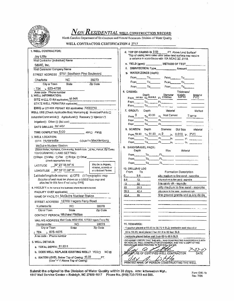
NON RESIDENTIAL WELL CONSTRUCTION RECORDNorth Carolina Department of Environment and Natural Resources- Division of Water Quality
WELL CONTRACTOR CERTIFICATION # 2717
1. WELL CONTRACTOR:
Jay LittleWell Contractor (Individual) Name
S&ME, Inc.Well Contractor Company Name
STREET ADDRESS 9751 Southern Pine Boulevard
Charlotte NC 28273
City or Town State Zip Code
704 )-. 523-4726Area code- Phone number
2. WELL INFORMATION:SITE WELL ID #(if applicable) M-34R
STATE WELL PERMIT#(if applicable)
DWQ or OTHER PERMIT #(If applicable) 70000752WELL USE (Check Applicable Box) Monitoring MJ Municlpal/PubiicO
IndustriallCommercial 0 Agricultural 0 Recovery D Injection [I
Irrigationo Other 0 (list use)
DATE DRILLED 05/14/07
TIME COMPLETED 5:00 AM o PM El
3. WELL LOCATION:CITY: Huntersvtlle COUNTY Mecklenburg
McGuire Nuclear Station(Street Name, Numbers, Community, Subdivision, Lot No., Parcel, Zip Code)
TOPOGRAPHIC / LAND SETTING:OSlope OValley []Flat (]Ridge 0 Other
(check appropriate box)
LATITUDE 35' 25' 55,94" N May be in degrees,minulltest seconds or
LONGITUDE 80' 56' 27.38" W in a decimal format
Latitude,/ongitude source: uGPS ElTopographic map(location of well must be shown on a USGS topo map andattached to this form if not using GPS)
4. FACILITY. is the name of the business where the well Is located.
FACILITY ID #(if applicable)_
NAME OF FACILITY McGuire Nuclear Station
STREET ADDRESS 12700 Hagers Ferry Road
Huntersvllle NC 28078City or Town State Zip Code
CONTACT PERSON Michael Phillips
MAILING ADDRESS Mail Code MG01EM, 12700 Hagers Ferry RdHuntersville NC 28078
City or Town State Zip Code
704 )875-4675Area code - Phone number
5. WELL DETAILS:
a. TOTAL DEPTH: 61,90 It
b. DOES WELL REPLACE EXISTING WELL? YES 0 NO 91
c. WATER LEVEL Below Top of Casing: 45.33 FT.(Use "+" if Above Top of Casing)
d, TOP OF CASING IS 2.93 FT. Above Land Surface-'Top of casing terminated at/or below land surface may require
a variance In accordance with 15A NCAC 2C .0118,
e. YIELD (gpm): _ METHOD OF TEST
f. DISINFECTION: Type_____ Amount
g. WATER ZONES (depth):
From- To_ From - To
From_ To_ From - To
From_ To_ From_ To
6. CASING: Thickness/Depth Diame er' g aarll
From 2,•ALS To E8.9081s Ft. 2 inchese
From - To_ Ft. _ _
From_ To_ Ft.__
7. GROUT: Depth Material Method
From 0 To 40.00 Ft. Neat Cement Tremie
From To Ft.
From_ To Ft.
8. SCREEN: Depth Diameter Slot Size Material
From 56.90 To 61.90 Ft.2
in. 0.010 in. PVCFrom_ To _ Ft. In. - in.
From_ To_ Ft. inL , in.
9, SAND/GRAVEL PACK;Depth Size Material
From To_ Ft._
From To_ Ft._
From To_ Ft.
10. DRILLING LOGFrom To Formation Description
0 9.8 silty medium to fine sand - saorolite
9.8 13 silty medium to tine sand -sapfolile
13 33 line sandy silt - saprolite
33 39.3 silty medium to fine sand - saprolite39.3 42.4 silty coarse to line sand - weathered rock
42.4 65 fine gralned granite and quartz diorite
11. REMARKS:- K-packer placed at 55.25 to 56.75 it BLS; bentonite seal placed at
40 to 55.25; sand placed from 61.9 to 63 feet BLS
- benlonille placed below well from 63 to 65 It BLS
I 00 HEREBY CERTIFY THAT THIS WELL WAS CONSTRUCTED IN ACCORDANCE WITH15A NCAC 2C, WELL CONSTRUCTION STANDARDS, AND THATA COPY OF THISREC0ORD3 BEEN PROVIDED TO THE WE. OWNR.
ý,eev' 4e, ý ,,8TrGI'URE OF CERTIFIED WELL CONTRACTOR
c,,y V~ /,YY4DATE
PRINTE5 NAME OF PERSON CONSTRUCTING THE WELL
Submit the original to the Division of Water Quality within 30 days. Attn: Information Mgt.,1617 Mail Service Center - Raleigh, NC 27699-1617 Phone No. (919) 733-7015 ext 568. Form GW-lb
Rev. 7/05
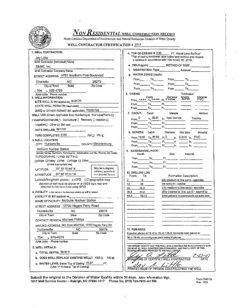
NON RESIDENTIAL WELL CONSTRUCTION RECORDNorth Carolina Department of Environment and Natural Resources- Division of Water Quality
WELL CONTRACTOR CERTIFICATION # 2717
1. WELL CONTRACTOR:
Jay LittleWell Contractor (Individual) Name
S&ME, Inc.Well Contractor Company Name
STREET ADDRESS 9751 Southern Pine Boulevard
Charlotte NC 28273City or Town State Zip Code
704 ). 523-4726Area code- Phone number
2. WELL INFORMATION:SITE WELL ID #(If applicable) M-34DR
STATE WELL PERMIT#(if applicable)
DWQ or OTHER PERMIT #(If applicable) 70000752
WELL USE (Check Applicable Box) Monitoring Mj MunIcipal/Public 0
Industrial/Commercial 0 Agricultural El Recovery [: Injection 0
Irrigatlono Other El (list use)_
DATE DRILLED 05/17/07
TIME COMPLETED 5:00 AMo PMzi
3. WELL LOCATION:CITY: Huntersville COUNTY Mecklenburg
McGuire Nuclear Station(street Name. Numbers. Community, Subdivision, Lot No., Parcel, Zip Code)
TOPOGRAPHIC / LAND SETTING:DSIope oValley OFlat []Ridge 0 Other
(check a pproprlate box)
LATITUDE 350 25' 55.94" N May be in degrees,Iminutcs, seconds orLONGITUDE 800 56' 27.31"W ini decimal format
Latitude/longitude source: RGPS oTopographic map(location of we/ must be shown on a USGS topo map and
attached to this form if not using GPS)
4. FACILITY- is the name of the business where the well Is located.
FACILITY ID #(if applicable)
NAME OF FACILITY McGuire Nuclear Station
STREET ADDRESS 12700 Hagers Ferry Road
Huntersville NC 28078City or Town State Zip Code
CONTACT PERSON Michael Phillips
MAILING ADDRESS Mail Code MG01EM, 12700 Hagers Ferry RdHuntersvIlle . NC 28078
City or Town State Zip Code
704 )- 875-4675
Area code- Phone number
5. WELL DETAILS:
a. TOTAL DEPTH: 89,90 it
b. DOES WELL REPLACE EXISTING WELL? YES 0 NO 1
c. WATER LEVEL Below Top of Casing: 45.97 FT.(Use "-I" If Above Top of Casing)
d. TOP OF CASING IS 3.20 FT. Above Land Surface*'Top of casing terminated at/or below land surface may require
a variance in accordance with 15A NCAC 2C.0118.
e. YIELD (gpm): - METHOD OF TEST_
f. DISINFECTION: Type_ _ Amount
g. WATER ZONES (depth):
From_ To From_ To
From To From - To
From_ To From_ To
6. CASING: Thickness/Depth Diameter 0elhg Nat~rial
From __2OALO To 70.0oeLS Ft. 2 inches c 4 VFrom_ To_ Ft._ _From_ To_ Ft._ _
7. GROUT: Depth Material Method
From__ _ To_38.00 Neat Cement TremieFrom 0 To Ft.
From To _ Ft.
8. SCREEN: Depth Diameter Slot SIze Material
From 79.90 To 89.90 Ft,2
In. 0.010 In. PVC
From _ To__ Ft. In, _ In.
From_ To_ Ft, in. _ in.
9. SAND/GRAVEL PACK:
Depth Size Material
From To Ft._
From To_ Ft.
From To_ Ft.
10, DRILLING LOGFrom To Formation Description
0 13 silty medium to fine sand - saprolite
13 33 line sandy sil -saprolite
33 39.3 silty medium to fine sand - saprolite39.3 44.2 silty coarse to fine sand - saprolite
44.2 90.10 coarse grained to line grained granite and quartz dorite
It. REMARKS:K-packer placed at 78.45 to 79.95 it BLS; bentonite seal placed at
38 to 78.45; no sand/gravel pack below K-packer
I OHEREBY CERTIFY THAT THIS WELL WAS CONSTRUCTED IN ACCORDANCE WITH15A NCAC 20, WELL CONSTRUCTION STANDARDS, AND THAT A COPY OF THISRE:CDRZ S BEEN PROVIDED To THEfLC OWN3R.
AfGNfRE OF CERT[FIED WELL CONTRACTOR DATE
PRINTED NAME OF PERSON CONSTRUCTING THE WELL
Submit the original to the Division of Water Quality within 30 days. Attn: Information Mgt.,1617 Mail Service Center - Raleigh, NC 27699-1617 Phone No. (919) 733-7015 ext 568.
Form GW-lbRev. 7/05

N;S&ME
July 31, 2007
North Carolina Department of Environment and Natural ResourcesDivision of Water Quality1617 Mail Service CenterRaleigh, North Carolina 27699-1617
ATTN: Information Management
Reference: NON-RESIDENTIAL WELL CONSTRUCTION RECORDS - SUBMITTAL #3McGUIRE NUCLEAR STATION12700 Hagers Ferry RoadHuntersville, North CarolinaS&ME Project No. 1264-06-724
Ladies and Gentlemen:
On behalf of Duke Energy, S&ME, Inc. (S&ME) is submitting the enclosed completed and signed Non-Residential Well Construction Records for the following six (6) groundwater monitoring wells installed atthe McGuire Nuclear Station (MNS) site:
• M-30 • M-33* M-30R • M-34R• M-32 • M-34DR.
Duke Energy is voluntarily installing groundwater monitoring wells at MNS as part of a site-widehydrogeologic evaluation. S&ME will submit these Non-Residential Well Construction Records on aperiodic basis as well installations are completed, this being the third submittal (i.e., Submittal #3).
On behalf of Duke Energy, S&ME thanks you for your receipt of these records. Should you have anyquestions or need additional information, please contact us.
Sincerely,S&ME, Inc.
Mary Beth Cline, E.I.T.
Staff Professional
enclosures
cc: Messrs. Steve LeRoy, Ed Sullivan, Tim Hunsucker; Duke Energy
SAEN VIIRON\2006\1264 Projects\6406724 McGuire Nuclear Groundwater Study\MCDENR Well RecordsVicdenr well records submittal 3.doc
S&ME, INC. / 155 Tradd Street / Spartanburg, SC 29301 /p 864.574.2360 f 864.576.8730
1 Marcus Drive / Greenville, SC 29615 / p 864-232-8987 / www.smeinc.com

d ~ 4
NON RESIDENTIAL WELL CONSTRUCTION RECORDNorth Carolina Department of Environment and Natural Resources- Division of Water Quality
WELL CONTRACTOR CERTIFICATION # 3439
1. WELL CONTRACTOR:
Justin MillwoodWell Contractor (individual) Name
S&ME, Inc.
Well Contractor Company Name
STREET ADDRESS 155 Tradd Street
Spartanburg SC 29301
City or Town State Zip Code
(864 )-_ 574-2360Area code- Phone number
2. WELL INFORMATION:SITE WELL ID #(if applicable)_ M30
STATE WELL PERMIT#(if applicable)
DWQ or OTHER PERMIT #(if applicable) 70000752
WELL USE (Check Applicable Box) Monitoring El Municipal/Public 0
Industrial/Commercial 0 Agricultural 0 Recovery o Injection [3
Irrigation[j] Other 0 (list use)
DATE DRILLED 5/17/07
TIME COMPLETED 5:00 AM O PM l]
3. WELL LOCATION:
CITY: Huntersville COUNTY Mecklenburg
McGuire Nuclear Station
(Street Name, Numbers, Community, Subdivision, Lot No., Parcel, Zip Code)
TOPOGRAPHIC / LAND SETTING:
rSIope EiValley EIFlat oRidge 0 Other(check appropriate box)
LATITUDE 35* 25' 38.41" N May be in degrees,ininutes, seconds orLONGITUDE 80" 57' 02.96" W in a decimal format
Latitude/longitude source: f GPS Ei Topographic map(location of well must be shown on a USGS topo map andattached to this form if not using GPS)
4. FACILITY- is the name ot the business where the well Is located.
FACILITY ID #(if applicable)
NAME OF FACILITY McGuire Nuclear Station
STREET ADDRESS 12700 Hagers Ferry Road
Huntersville NC 28078
d. TOP OF CASING IS 3.04 FT. Above Land Surface**Top of casing terminated at/or below land surface may require
a variance in accordance with 15A NCAC 2C .0118.
e. YIELD (gpm): METHOD OF TEST
f. DISINFECTION: Type Amount
g. WATER ZONES (depth):
From_ To_ From_ To
From_ To_ From_ To
From_ To_ From_ To
6. CASING: Thickness/Depth Diameter Veight Material
From 3.04ALS To 35.70 Ft. 2 inches ch40 PVC
From_ To_ Ft._
From_ To_ Ft._
7. GROUT: Depth Material Method
From 0 To 30.70 Ft. Portland Tremie
From To Ft.
From_ To_ Ft.
8. SCREEN: Depth Diameter Slot Size Material
From 35.70 To 50.70 Ft.2
in. 0.010 in. PVC
From To Ft. in. i n.
From_ To_ Ft. in. 'in.
9. SANDIGRAVEL PACK:Depth Size Material
From 33.00 To 50.70 Ft. #1 Filter Sand
From To_ Ft._
From To Ft._
10. DRILLING LOGFrom To
0 13.5
13.5 22
22 2727 3232 4242 47.8
47.8 50.7
11. REMARKS:
Formation Descriptionslightly sandy, clayey, silt - saprolite
siltv fine sand - saprolite
silty medium to fine sand - saproliteslightly sandy, silt - saproliteclayey, silt - saprolite
slightly sandy, silt - saprolitesilty, medium to fine sand - saprolite
City or Town State Zip Code
CONTACT PERSON Michael Phillips
MAILING ADDRESS Mail Code MG01 EM, 12700 Hagers Ferry Road
Huntersvilie NC 28078City or Town State
7Z04_ )_ 875-4675
Area code - Phone number
Zip Code
5. WELL DETAILS:
a. TOTAL DEPTH: 50.70 feet
b. DOES WELL REPLACE EXISTING WELL? YES 0 NO 0N
c. WATER LEVEL Below Top of Casing: 45.63 FT.(Use +" if Above Top of Casing)
I DO HEREBY CERTIFY THAT THIS WELL WAS CONSTRUCTED IN ACCORDANCE WITH"SA NCAC/,* WELL CONSTRUCTION STA EDSO, AND THAT A COPY OF THISRECORD4IAS BEEN PROVIDEDT TH-ELL ONNER.
ATURE OF CERTIFIED WELL CONTRACTOR DATE-- U~si - 7J, l.. oo c
PRINTED NAME OF PERSON CONSTRUCTING THE WELL
Submit the original to the Division of Water Quality within 30 days. Attn: Information Mgt.,1617 MalI Service Center - Raleigh, NC 27699-1617 Phone No. (919) 733-7015 ext 568.
Form GW-lbRev. 7/05

NON RESIDENTIAL WELL CONSTRUCTION RECORDNorth Carolina Department of Environment and Natural Resources- Division of Water Quality
WELL CONTRACTOR CERTIFICATION # 3439
1. WELL CONTRACTOR:
Justin Millwood
Well Contractor (Individual) Name
S&ME, Inc.
Well Contractor Company Name
STREET ADDRESS 155 Tradd Street
Spartanburg SC 29301
City or Town State Zip Code
864 -_574-2360
Area code- Phone number2. WELL INFORMATION:
SITE WELL ID #(it applicable) M-30R
STATE WELL PERMIT#(if applicable)_
DWQ or OTHER PERMIT #(if applicable) 70000752
WELL USE (Check Applicable Box) Monitoring EI Municipal/Public L-
industrial/Commercial E Agricultural o Recovery El Injection E[
IrrigationD Other 0 (list use)
DATE DRILLED 5/14/07
TIME COMPLETED 5:00 AM o PM E]
3. WELL LOCATION:
CITY: Huntersville COUNTY Mecklenburg
McGuire Nuclear Station
(Street Name, Numbers, Community, Subdivision, Lot No., Parcel, Zip Code)
TOPOGRAPHIC / LAND SETTING:
ElSIope oValley DFlat DRidge El Other(check appropriate box)
LATITUDE 35' 25' 38.43" N May be in degrees,minutes, scconds or
LONGITUDE 80' 57' 02.92" W in a decimal format
Latitude/longitude source: EGPS ElTopographic map
(location of well must be shown on a USGS topo map andattached to this form if not using GPS)
4. FACILITY- is the name of the business where the well is located.
FACILITY ID #(if applicable)
NAME OF FACILITY McGuire Nuclear Station
STREET ADDRESS 12700 Hagers Ferry Road
Huntersville NC 28078
City or Town State Zip Code
CONTACT PERSON Michael Phillips
MAILING ADDRESS Mail Code MGO0 EM, 12700 Hagers Ferry Road
Huntersville NC 28076
City or Town State Zip Code
(704 ). 875-4675
Area code - Phone number
5. WELL DETAILS:
a. TOTAL DEPTH: 78.50 feet
b. DOES WELL REPLACE EXISTING WELL? YES El NO L]
c. WATER LEVEL Below Top of Casing: 46.07 FT.(Use "+" if Above Top of Casing)
d. TOP OF CASING IS 3.19 FT. Above Land Surface**Top of casing terminated at/or below land surface may require
a variance in accordance with 15A NCAC 2C .0118.
e. YIELD (gpm): METHOD OF TEST
f. DISINFECTION: Type Amount
g. WATER ZONES (depth):
From_ To_ From_ To
Fromm_ To From To
From_ To - From_ To
6. CASING: Thickness/Depth Diameter Weight Material
From 3.19 ALS To 73.50 Ft. 2 inches Sch 40 PVC
From_ To_ Ft._
From_ To - Ft._
7. GROUT: Depth Material Method
From 0 To 70.00 Ft. Neat Cement Tremie
From To Ft.
From _ To Ft.
8. SCREEN: Depth Diameter Slot Size Material
From 73.50 To_78.50 Ft.2 in. 0.010 in. PVCFrom_ To _ Ft. in. _ in.
From_ To _ Ft. in. _ in.
9. SAND/GRAVEL PACK:Depth Size Material
From 78.50 To 80.30 Ft. #2 Filter Sand
From To_ Ft._
From To _ Ft._
10. DRILLING LOGFrom To
0 13.513.5 22
22 27
27 3232 4242 47.8
47.8 69.7
69.7 76.1
76.1 89.55
Formation Description
sliqhtly sandy, clayey, silt - saprolitesilty fine sand -saprolile
silty medium to fine sand - saprolite
slightly sandy, silt - saproliteclayey, silt - saprolite
slightly sandy, silt - saprolite
silty, medium to fine sand - saprolite
medium arained oranite - weathered rock
medium grained quartz diorite
11. REMARKS:- bentonite placed below well from 80,30 to 89.55 It BLS
- k-packer placed at 71.45 to 72.95 1t BLS; bentonite seal placed at
70.00 to 71.45 feet BLS; no sand/gravel pack below K-packer.
I DO HEREBY CERTIFY THAT THIS WELL WAS CONSTRUCTED IN ACCORDANCE WITHT5A NcAc 2EF, WELL CONSTRUCTION STANDARDS. AND THAT A COPY OF THIS
RECO:R7D BEEN TR O ET70hE ELL /
SrI TURE OF CERTIFIED WELL CONTRACTOR DA\TE
PRINTED NAME OF PERSON CONSTRUCTING THE WELL
Submit the original to the Division of Water Quality within 30 days. Attn: Information Mgt.,1617 Mail Service Center- Raleigh, NC 27699-1617 Phone No. (919) 733-7015 ext 568. Form GW-lb
Rev. 7/05

NoNRESIDENTIAL WELL CONSTRUCTION RECORDNorth Carolina Department of Environment and Natural Resources- Division of Water Quality
WELL CONTRACTOR CERTIFICATION # 2717
1. WELL CONTRACTOR:
Jay LittleWell Contractor (Individual) Name
S&ME, Inc.Well Contractor Company Name
STREET ADDRESS 9751 Southern Pine Boulevard
Charlotte NC 28273City or Town State Zip Code
(704 _) 523-4726Area code- Phone number
2. WELL INFORMATION:SITE WELL ID #(If applicable) M-32
STATE WELL PERMIT#(ir applicable)_
DWQ or OTHER PERMIT #(if applicable) 70000752
WELL USE (Check Applicable Box) Monitoring M] Munlclpal/Public [I
Industrial/Commercial D Agricultural 0 Recovery 0 Injection 0
Irrigationo Other 0 (list use) _
DATE DRILLED 05103/07
TIME COMPLETED 5:00 AMC] PM[!9
3. WELL LOCATION:CITY: Huntersville COUNTY Mecklenburg
McGuire Nuclear Station(Street Name, Numbers, Community, Subdivision, Lot No., Parcel, Zip Code)
TOPOGRAPHIC / LAND SETTING:
o Slope EOValley D Flat 0 Ridge 0 Other(check appropriate box)
LATITUDE 25' 25' 39.25" N May be in degrees,minutes, secornds or
LONGITUDE Q0* 56' 37.39" W in a decimal fbrmat
Latitude/tongitude source: vGPS oTopographic map(location of well must be shown on a USGS topo map andattached to this form if not using GPS)
4, FACILITY. is the name or the business where the watl ts located,
FACILITY ID #(If applicable)
NAME OF FACILITY McGuire Nuclear Station
STREET ADDRESS 12700 Hagers Ferry Road
Huntersville NC 28078
d. TOP OF CASING IS 2.98 FT. Above Land Surface**Top of casing terminated at/or below land surface may require
a variance In accordance with ISA NCAC 20 .0118.
e. YIELD (gpm): _ METHOD OF TEST
f. DISINFECTION: Type_ __ Amount
g. WATER ZONES (depth):
From- To_ From To
From.__ To From To
From_ To_ From_ To
6. CASING: Thickness/Depth Diameter Welght• ierial
From 2,98ALS To 4a.0 La FL 2 Inches ch4 V
From___ To_ _ Ft._ _From To_ __ Ft
7. GROUT: Depth Material MethodFrom 0 To 35.00 Fl, Neat Cement Tremle
From0 To_ Ft.From _ To_ Ft.
8. SCREEN: Depth Diameter Slot Size Material
From 40.00 To_55.00 Ft.2 In. 0.010 In. PVC
From To Ft. in, In.
From_ To Ft. in. In.
9. SAND/GRAVEL PACK:Depth Size Material
From 37.00 To 56.00 Ft. #1 Filter Sand
From To_ _Ft.,From To_ Ft.
10. DRILLING LOGFrom To Formation Description
n 6 fine cnnarl•j notnmv r iit . nnnreliti
6 12
12 1717 23
23 42
42 47
47 5353 5666 60,4
11. REMARKS:
silty line sned - Baprolite
clavev fine sand - saorolitesilty medium to fine sand - saprolitesilty line sand. saprollie
silty medium to fine sand - saprolite
slightly clayey silty fine sand - saprolaealohlhv sandy silt - saorolile
shIlV coarse to tine sand - weathered rock
City or Town State Zip Code
CONTACT PERSON Michael Phillips
MAILING ADDRESS Malt Code MD01 EM, 12700 Hagers Ferry RdHuntersville NC 28078
City or Town State Zip Code
704 ). 875-4675Area code - Phone number
5. WELL DETAILS:
a. TOTAL DEPTH: 55.00 ft
b. DOES WELL REPLACE EXISTING WELL? YES 0 NO M
c. WATER LEVEL Below Top of Casing: 54.09 FT.(Use "" If Above Top of Casing)
I DO HEREBY CERTIFY THAT THIS WELL WAS CONSTRUCTED IN ACCORDANCE WITHISA NCAC 20. WELL CONSTRUCTION STANDARDS, AND THATA COPY OF THISR D BEEN PROVIDED TOTH. EL N
r
.'GNIXRE OF CERTIFIELMELL CONTRACTORZ 'I, DATE
PRINTEd NAME OF PERSON CONSTRUCTING THE WELL
Submit the original to the Division of Water Quality within 30 days. Attn: Information Mgt.,1617 Malil Service Center- Raleigh, NC 27699-1617 Phone No. (919) 733.7015 ext 568.
Form GW-lbRev. 7/05

NON RESIDENTIAL WELL CONSTRUCTION RECORDNorth Carolina Department of Environment and Natural Resources- Division of Water Quality
WELL CONTRACTOR CERTIFICATION Y 2717
1, WELL CONTRACTOR:
Jay LittleWell Contractor (individual) Name
S&ME, Inc.Well Contractor Company Name
STREET ADDRESS 9751 Southern Pine Boulevard
Charlotte NC 28273City or Town State Zip Code
704 .. 523-4726Area code- Phone number
2. WELL INFORMATION:
SITE WELL ID #(If applicable) M-33
STATE WELL PERMIT#(If applicable)
DWQ or OTHER PERMIT #(If applicable) 70000752
WELL USE (Check Applicable Box) Monitoring 0 MunIcipal/Public o
Industrial/Commercial El Agricultural El Recovery [l Injection El
IrrigatIonC3 Other ol (list use)
DATE DRILLED 05/11/07
TIME COMPLETED 5:00 AM o] PM In
3. WELL LOCATION:
CITY: Huntersville COUNTY Mecklenburg
McGuire Nuclear Station(Street Name, Numbers, Community, Subdivision, Lot No., Parcel, Zip Code)
TOPOGRAPHIC I LAND SETTING:
E]Siope EValley CFlat DRidge El Other(check appropriate box)
LATITUDE 350 25' 41.90' N May be in degrees,minutes, seconds or
LONGITUDE 80* 56' 24.34- W iii a decimal formao
Latitude/longitude source: gxGPS ElTopographic map(location of well must be shown on a USGS topo map andattached to this form if not using GPS)
4. FACILITY- is the name of the business where the well 1t5 locted,
FACILITY ID #(if applicable)
NAME OF FACILITY McGuire Nuclear Station
STREET ADDRESS 12700 Hagers Ferry RoadHuntersvltle NC 28078
d. TOP OF CASING IS 3.05 FT. Above Land Surface**Top of casing terminated at/or below land surface may require
a variance In accordance with 15A NCAC 2C .0118.
a. YIELD (gpm): _ METHOD OF TEST
f. DISINFECTION; Type_________ Amount
g. WATER ZONES (depth):
From_ To_ From - To
From To_ From_ To
From_ To_ From_ To_____
6. CASING: Thickness/Depth slameter leight Mteial
From s3o ALS To 0,00n1LS Ft. 2 inches 40 P
From_ To_ Ft. _ _
From - To_ Ft. _ _
7. GROUT: Depth Material Method
From 0 To 19.00 Ft. Neat Cement Tremle
From To Ft.
From_ To_ Ft.
6. SCREEN: Depth Diameter Slot Size Material
From 23.00 To 38.00 Ft. 2 in. 0.010 in, PVCFrom_ _ To Ft. In. In.
From_ To _ Ft. in. In.9, SAND/GRAVEL PACK:
Depth Size Material
From 21.00 To38-00 Ft, #1 Filter SandFrom To______ Ft._From To _ Ft.
10. DRILLING LOGFrom To Formation Description
silty r.Itv - sAnroMiti0 77 8.7
8.7 9
9 1212 22
22 2727 34.434.4 3737 46.348.3 49.a
11, REMARKS:
slightly clayey tine sandy silt - saprolile
silty clay - saprolite
sllhtilv clayey fine sandy silt - saoroliteline sandy silt -sapralite
clayey line sandy silt - saprolite
sliohtlv clayey fine sandy silt - saoroliltfine sandy silt - saprolite
silty medium to line sand - saprolite
City or Town Stale Zip Code
CONTACT PERSON Michael Phillips
MAILING ADDRESS Mail Code MG01EM, 12700 Hagers Ferry RdHuntersvllle NO 28078
silly medium to line sand- weathered rock
City or Town State
(704 ). 875-4675
Area code - Phone number'
Zip Code
5. WELL DETAILS:
a. TOTAL DEPTH: 38.00 it
b. DOES WELL REPLACE EXISTING WELL? YES [I NO I[
c. WATER LEVEL Below Top of Casing: 30.57 FT,(Use"+" If Above Top of Casing)
I DO HEREBY CERTIFY THAT THIS WELL WAS CONSTRUCTED IN ACCORDANCE WITHISA NCAC 2C, WELL CONSTRUCrTION STANDARDS, AND THAT A COPY OF THIS
,R BEEN PROFCERToIDED THE LI.L 0 NTRA
0%fI§NRRE OF CERTIFIED WELL CONTRACTOR DATE
PRINTED'NAME OF PERSON CONSTRUCTING THE WELL
Submit the original to the Division of Water Quality within 30 days. Attn: Information Mgt.,1617 Mail Service Center - Raleigh, NC 27699-1617 Phone No. (919) 733-7015 ext 568. Form GW-lb
Rev. 7/05

NON RESIDENTIAL WELL CONSTRUCTION RECORD
North Carolina Department of Environment and Natural Resources- Division of Water Quality
WELL CONTRACTOR CERTIFICATION # 2717
d. TOP OF CASING IS 2.93 FT. Above Land Surface1. WELL CONTRACTOR:
Jay LittleWell Contractor (Individual) Name
S&ME, Inc.Well Contractor Company Name
STREET ADDRESS 9751 Southern Pine Boulevard
Charlotte NC 28273City or Town State Zip Code
704 )- 523-4726Area code- Phone number
2. WELL INFORMATION:SITE WELL ID #(if applicable) M-34R
STATE WELL PERMIT#0(f applicable)
DWQ or OTHER PERMIT #(If applicable) 70000752
WELL USE (Check Applicable Box) Monitoring M Municipal/Public 0
IndustriallCommercial 0 Agricultural 0 Recoveryo Injection rl
IrrigationDl Other 0 (list use)
DATE DRILLED 05114(07
TIME COMPLETED 5:00 AMO PM El
3. WELL LOCATION:CITY: Hunteraville COUNTY Mecklenburg
McGuire Nuclear Station
d. TOP OF CASING IS 2.93 FT. Above Land Surface**Top of casing terminated atlor below land surface may require
a variance In accordance with 15A NCAC 2C .0118.
e. YIELD (gpm): _ METHOD OF TEST
f. DISINFECTION: Type_ _ Amount
g. WATER ZONES (depth):
From - To From - To
From To_ From_ To_
From To_ From To_ _
6. CASING: Thickness/Depth Diameter eighI lrisl
From 2-,3A h To l.216Le Ft. 2 InchesFrom - To Ft._
From__ To_ _ Ft._
7. GROUT: Depth Material Method
From 0 To 40.00 Ft. Neat Cement TremieFrom To Ft.
From____ To _ Ft.
8. SCREEN: Depth Diameter Slot Size Material
From 56.90 To 61.90 Ft.2 in. 0.010 in. PVCFrom____ To__ Ft. In. in.
From _ To _ Ft. in. _ in.
9. SAND/GRAVEL PACK:Depth Size Material
From To _ Ft.
From To Ft.
From To_ Ft.
10. DRILLING LOGFrom To Formation Description
0 9.8 silty medium to fine sand - saprolite9.8 13 silty medium to line sand - sepiolils13 33 fine sandy silt - saprolite33 39.3 silty medium to fine sand - saprolite39.3 42.4 silty coarse to line sand -weathered rack
42.4 65 tine gralned granite and quartz diorite
11, REMARKS:- K-packer placed at 55.25 to 56.75 ft BLS; bentonite seal placed at
(Street Name, Numbers, Community, Subdivision, Lot No., Parcel, Zip Code)TOPOGRAPHIC / LAND SETTING:
:Slope oVElley OFlat 0 Ridge E[ Other
(check appropriate box)
LATITUDE 350 25' 55.94" N May be in degrees,minutes, seconds or
LONGITUDE 80" 68' 27.38" W in a decimal formal
Latit-ade/longitude source: vGPS oTopographic map(localion of well must be shown on a USGS topo map andattached to this form if not using GPS)
4. FACILITY- is the name of ihe business where the well Is located.
FACILITY ID #(if applicable)_
NAME OF FACILITY MCGuire Nuclear Station
STREET ADDRESS 12700 Hagers Ferry Road
Huntersvllle NC 28078
City or Town State Zip Code
CONTACT PERSON Michael Phillips
MAILING ADDRESS Mall Code MG01 EM, 12700 Hagers Ferry Rd
HuntersvIltle NC 28078City or Town State Zip Code
704 ). 875-4675
Area code - Phone number
5. WELL DETAILS:
a. TOTAL DEPTH: 61.90 It
b. DOES WELL REPLACE EXISTING WELL? YES El NO 9
c. WATER LEVEL Below Top of Casing: 45.33 FT.(Use "+" If Above Top of Casing)
40 to 55,25; sand placed from 61.9 to 83 feet BLS
-bentonite placed below well from 63 to 65 It BLS
I DO HEREBY CERTIFY iTHAT"THIS WELL WAS CONSTRUCTED IN ACOORDANCE WITH15A NOAC 2C, WELL CONSTRUCTION STANDARDS, AND THAT A COPY OF THISRECORDS , BEEN PROVIDED TO TE W R.
~~•j~~-~C >27 ?i'
RE OF CERTIFIED WELL CONTRACTOR I
PRIINTE5 LNAME OF PERSON CONSTRUCTING THE WELL
)ATE
Submit the original to the Division of Water Quality within 30 days. Attn: Information Mgt.,1617 MalI Service Center- Raleigh, NC 27699-1617 Phone No. (919)733-7015 ext 568.
Form GW-lbRev. 7/05

lVoN RESIDENTIAL WELL CONSTRUCTION RECORD
North Carolina Department of Environment and Natural Resources- Division of Water Quality
WELL CONTRACTOR CERTIFICATION # 2717
d. TOP OF CASING IS 3.20 FT. Above Land Surf ace5
1. WELL CONTRACTOR:
Jay LittleWell Contractor (Individual) Name
S&ME, Inc.Well Contractor Company Name
STREET ADDRESS 9751 Southern Pine Boulevard
Charlotte NO 28273
City or Town State Zip Code
)704 . 523-4726Area code- Phone number
2. WELL INFORMATION:
SITE WELL ID #(If applicable) M-34DR
STATE WELL PERMIT#(if applicable)_
DWQ or OTHER PERMIT #(if applicable) 70000752
WELL USE (Check Applicable Box) Monitoring 91 Municipal/Public []
IndustriallCommercial Agricultural ID Recovery [] Injection []
IrrIgatlono Other ID (list use)
DATE DRILLED 05117107
TIME COMPLETED 5:00 AM[I PM E
3. WELL LOCATION:
CITY: Huntersville COUNTY Mecklenburg
McGuire Nuclear Station(Street Name, Numbars, Community, Subdivision, Lot No., Parcel, Zip Code)
TOPOGRAPHIC I LAND SETTING:
0SIope IDValley 0FIat []Ridge ID Other
(check appropriate box)
LATITUDE 35* 25' 55.94" N May be in degrees,minnuts, secornds or
LONGITUDE 80' 56' 27.31" W in a decimal format
Latitude/longitude source: uGPS DTopographie map(location of wail must be shown on a USGS (opo map andattached to this form if not using GPS)
4. FACILITY-is the name or the business where IhB well Is located.
FACILITY ID #(If applicable)
NAME OF FACILITY McGuire Nuclear Station
STREET ADDRESS 12700 Hagers Ferry Road
Huntersvlle NC 28078City or Town State Zip Code
CONTACT PERSON Michael Phillips
MAILING ADDRESS Mail Code MG01EM, 12700 Hagers Ferry Rd
Huntersvilie NC 28078City or Town State Zip Code
704 . . 875-4675Area code a Phone number
5. WELL DETAILS:
a. TOTAL DEPTH: 89.90 it
b. DOES WELL REPLACE EXISTING WELL? YES ID NO M]
c. WATER LEVEL Below Top of Casing: 45.97 FT.(Use "+" If Above Top or Casing)
d. TOP OF CASING IS 3.20 .FT. Above Land Surface'*Top of casing terminated at/or below land surface may require
a variance In accordance with 15A NCAC 2C .0118.
a. YIELD (gpm): _ METHOD OF TEST
f. DISINFECTION: Type_..____ Amount.
g, WATER ZONES (depth):
From_ To From__ To
From To From_ To
From_ To_ From To. _
6. CASING: Thickness/Depth Diameter s 4elhg 00t1 rlal
From .As To 70n,0L Ft. 2 inches ch r
From_ To_ Ft._ _
From_ To_ Ft._ _
7. GROUT: Depth Material Method
From 0 To 38.00 Ft. Neat Cement TremieFrom _ To Ft.
From To Ft.
8, SCREEN: Depth Diameter Slot Size Malarial
From 79.90 To_89.90 Ft. 2 In. 0,010 In. PVCFrom _ To _ Ft. in, _ In.
From_ _ To_ _ Ft. in. _ in.
9. SAND/GRAVEL PACK:Depth Size Material
From To Ft._
From To Ft.
From To Ft.
10. DRILLING LOGFrom To Formation Description
0 13 silty medium to fine sand - saprolite
13 33 line sandy sill -saprolite
33 39,3 silty medium to fine sand - saprolite39.3 44.2 silty coarse to fine sand - saprolite44.2 90.10 coarse gralned to line grained granlle end quartz dorile
11, REMARKS:K-packer placed at 78.45 to 79.95 It SLS; bentonite seal placed at
38 to 78,45; no sand/gravel pack below K-packer
100 HEREBY CERTIFY THAT THIS WELL WAS CONSTRUCTED IN ACCORDANCE WITHISA NCAC 20, WELL CONSTRUCTION STANDARDS. AND THATA COPY OF THISR EcOR",,1S BEEN PROVIOED 70 THE W OWN ,R.
, NfGN'RE OF CERTTFIED WELL CONTRACTOR DATE
PRINTED NAME OF PERSON CONSTRUCTING THE WELL
Submit the original to the Division of Water Quality within 30 days. Attn: Information Mgt.,1617 MalI Service Center - Raleigh, NC 27699-1617 Phone No. (919) 733-7015 ext 568.
Form GW-lbRev. 7/05
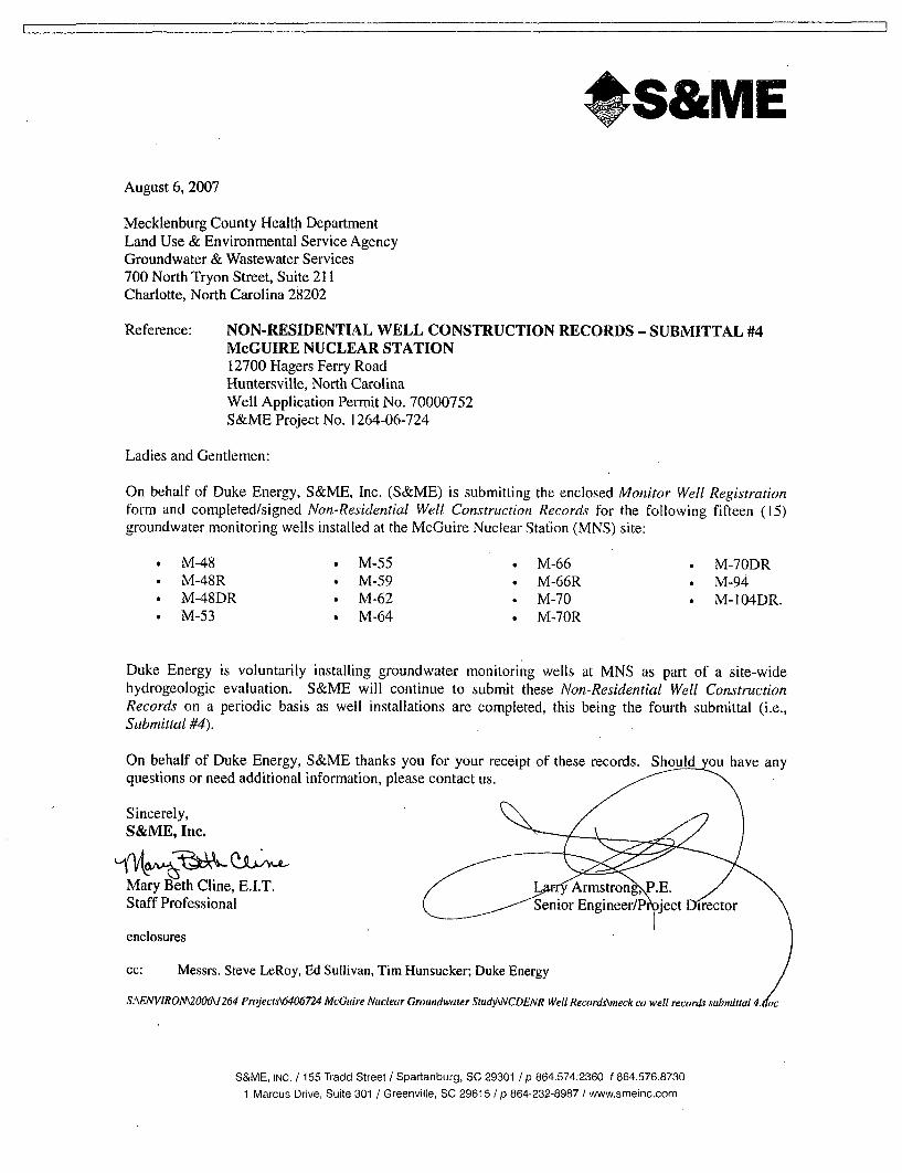
IrS&ME
August 6, 2007
Mecklenburg County Health DepartmentLand Use & Environmental Service AgencyGroundwater & Wastewater Services700 North Tryon Street, Suite 211Charlotte, North Carolina 28202
Reference: NON-RESIDENTIAL WELL CONSTRUCTION RECORDS - SUBMITTAL #4McGUIRE NUCLEAR STATION12700 Hagers Ferry RoadHuntersville, North CarolinaWell Application Permit No. 70000752S&ME Project No. 1264-06-724
Ladies and Gentlemen:
On behalf of Duke Energy, S&ME, Inc. (S&ME) is submitting the enclosed Monitor Well Registrationform and completed/signed Non-Residential Well Construction Records for the following fifteen (15)groundwater monitoring wells installed at the McGuire Nuclear Station (MNS) site:
* M-48 • M-55 • M-66 . M-70DR* M-48R * M-59 0 M-66R 0 M-94* M-48DR 0 M-62 0 M-70 * M-104DR.* M-53 0 M-64 e M-70R
Duke Energy is voluntarily installing groundwater monitoring wells at MNS as part of a site-widehydrogeologic evaluation. S&ME will continue to submit these Non-Residential Well ConstructionRecords on a periodic basis as well installations are completed, this being the fourth submittal (i.e.,Submittal #4).
On behalf of Duke Energy, S&ME thanks you for your receipt of these records. Should ou have anyquestions or need additional information, please contact us.
Sincerely,S&ME, Inc.
Mary Beth Cline, E.I.T. L Armstron , P.E.
Staff Professional Senior Engineer/P ject irector
enclosures
cc: Messrs. Steve LeRoy, Ed Sullivan, Tim Hunsucker; Duke Energy
S:\ENVIRONM2006V 264 Projects\6406724 McGuire Nuclear Groundwater StudyWCDENR Well Recordskneck co well records submittal 4.2c
S&ME, INC. / 155 Tradd Street / Spartanburg, SC 29301 / p 864.574.2360 f 864.576.87301 Marcus Drive, Suite 301 / Greenville, SC 29615 / p 864-232-8987 / www.smeinc.com
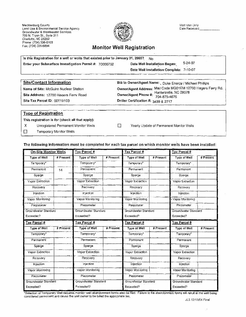
Mecklenburg CountyLand Use & Environmental Service AgencyGroundwater & Wastewater Services700 N. Tryon St., Suite 211Charlotte, NC 28202Phone: (704) 336-5103Fax: (704) 336-6894 Monitor Well Registration
Staff Use OnlyDate Received:
Is this Registration for a well or wells that existed prior to January 01, 2005?, No
Enter your Subsurface Investigation Permit #: 70000752 Date Well Installation Began: 5-24-07
Date Well Installation Complete: 7-10-07
Site/Contact Information Bill to Owner/Agent Name: . Duke Energy / Michael Phillips
Name of Site: McGuire Nuclear Station Owner/Agent Address: Mail Code MG01 EM 12700 Hagers Ferry Rd.Huntersville, NC 28078
Site Address: 12700 Haaers Ferry Road Owner/Agent Phone #: 704-875-4675704-875-4675
Site Tax Parcel ID: 00119103 Driller Certification #: 3439 & 2717
Type of Registration
This registration is for (check all that apply):
X Unregistered Permanent Monitor Wells El Yearly Update of Permanent Monitor Wells
III Temporary Monitor Wells
The following information must be completed for each tax parcel on which monitor wells have been installed:
On-Site Monitor Wells Tax Parcel # Tax Parcel # Tax Parcel #
Type of Well # Present Type of Well # Present Type of Well # Present Type of Well # Present
Temporary* Temporary* Temporary* Temporary*
Permanent 14 Permanent Permanent Permanent
Sparge Sparge Sparge Sparge
Vapor Extraction Vapor Extraction Vapor Extraction Vapor Extraction
Recovery Recovery Recovery Recovery
Injection Injection Injection Injection
Vapor Monitoring Vapor Monitoring Vapor Monitoring Vapor Monitoring
Piezometer Piezometer Piezometer Piezometer
Groundwater Standard Groundwater Standard Groundwater Standard Groundwater Standard
Exceeded? Exceeded? Exceeded? Exceeded?
Tax Parcel # Tax Parcel # Tax Parcel # Tax Parcel #
Type of Well # Present Type of Well # Present Type of Well # Present Type of Well # Present
Temporary* Temporary* Temporary* Temporary*
Permanent Permanent Permanent Permanent
Sparge Sparge Sparge Sparge
Vapor Extraction Vapor Extraction Vapor Extraction Vapor Extraction
Recovery Recovery Recovery Recovery
Injection Injection Injection Injection
Vapor Monitoring Vapor Monitoring Vapor Monitoring Vapor Monitoring
Piezometer Piezometer Piezometer Piezometer
Groundwater Standard Groundwater Standard Groundwater Standard Groundwater Standard
Exceeded? Exceeded? Exceeded? Exceeded?
*Selection of Temporary Well requires monitor well abandonment forms also be filed. Failure to file abandonment forms will result in the well being
considered permanent and cause the well owner to be billed the appropriate fee.JLS 12/13/04 Final

NON RESIDENTIAL WELL CONSTRUCTION RECORD
North Carolina Department orEnvironment and Natural Resources- Division of Water Quality
WELL CONTRACTOR CERTIFICATION # 2717
1. WELL CONTRACTOR:
Jay LittleWell Contractor (Individual) Name
S&ME, Inc.Well Contractor Company Name
STREET ADDRESS 9751 Southern Pine Boulevard
Charlotte NC 28273City or Town State Zip Code
_04 )- 523-4726Area code- Phone number
2. WELL INFORMATION:SITE WELL ID #(If applicable) M-48
STATE W ELL PERMIT#/if applicable)--
DWQ or OTHER PERMIT #(if applicable) 70000752
WELL USE (Check Applicable Box) Monitoring M] Muntolpal/Public 0
Industrial/Commercial 0 Agricultural 0 Recovery 0] Injection 0
Irrigationol Other 0 (list use)
DATE DRILLED 06/21/07
TIME COMPLETED 5:00 AM 0 PM El
3. WELL LOCATION:
CITY: Huntersville COUNTY Mecklenburg
McGuire Nuclear Station
d. TOP OF CASING IS 0.22 BLS FT. Above Land Surface**Top of casing terminated al/or below land surface may require
a variance In accordance with 15A NCAC 2C .0118.
a. YIELD (gpm): METHOD OF TEST__
f. DISINFECTION: Type Amount
g, WATER ZONES (depth):
From_ To_ From - To
From_ To - From_ To
From_ To - From_ To
6. CASING: Thickness/Depth Diameter eight Material
From 0.22BLs To 9,8e LS Ft. 2 inches cH 4 VUFrom - To - Ft._
From - To - Ft._
7, GROUT: Depth Material Method
From 0 To 4.5 Ft. Neat Cement TremieFrom_ To - Ft.
From - To Ft.
8. SCREEN: Depth Diameter Slot Size Material
From 9.8 To 19.8 Ft. 2 in. 0.010 in. PVCFrom___ FT. in. in. _
From_ To - Ft. in. In.
9. SAND/GRAVEL PACK:Deplh Size Material
From 6.5 To 19.8 Ft. #1 Filter Sand
From To_ Ft._
From To_ Ft._
10. DRILLING LOGFrom . To Formation Description
0 1 Gravel1 3.5 Sill-fill
3.5 6 Gravel6 14 fine sandy, clayey, silt - fill14 20.2 clayey, medium to lIne sandy - fill
11. REMARKS:Cave-In Irom 19.8 10 20.2 It BLS.
(Street Name. Numbers, Community, Subdivision, Lot No.. Parcel, Zip Code)
TOPOGRAPHIC / LAND SETTING:
L]Slope OValley OFlat oRidge 0 Other(check appropriate box)
LATITUDE 35' 26' 00.33' N May be in degrees,mininutes, Secontds ay
LONGITUDE 80' 56' 52,36" W in a dccimal format
Latirude/longitudesource: uGPS oTopographic map(location of well must be shown on a USGS topo map and
attached to this form if not using GPS)
4. FACILITY- is the name of the business where the well is located.
FACILITY ID #(if applicable)
NAME OF FACILITY McGuire Nuclear Station
STREET ADDRESS 12700 Hagers Ferry Road
Huntersville NC 28078
City or Town State Zip Code
CONTACT PERSON Michael Phillips
MAILING ADDRESS Mall Code MG01EM, 12700 Hagers Ferry Rd
Huntersville NC 28078City or Town State Zip Code
704 ). 875-4675
Area code m Phone number
5. WELL DETAILS:
a. TOTAL DEPTH: 19.8 it
b. DOES WELL REPLACE EXISTING WELL? YES El NO M]
c, WATER LEVEL Below Top of Casing: DRY FT.(Use "+" If Above Top of Casing)
I DO HEREBY CERTIFY THAT THIS WELL WAS CONSTRUCTED IN ACCORDANCE WITH15A NOAC 2C, WELL CONsTRn•CnON STANDARDS, AND THAT A COPY OF THISRECORD9,bIS BEEN PROYIDED OTHE WELL OWNER.
A ,,NP RE OF CERTIFIED WELL CONTRACTOR D
PRINTED NAME OF PERSON CONSTRUCTING THE WELL
Submit the original to the Division of Water Quality within 30 days. Attn: Information Mgt.,1617 Mail Service Center - Raleigh, NC 27699.1617 Phone No. (919) 733.7015 ext 568. Form GW-lb
Rev. 7/05

IoN RESIDENTLAL WELL CONSTRUCTION RECORD
North Carolina Department of Environment and Natural Resources- Division of Water Quality
WELL CONTRACTOR CERTIFICATION # 2717
1. WELL CONTRACTOR:
Jay LittleWell Contractor (Individual) Name
S&ME, Inc.Well Contractor Company Name
STREET ADDRESS 9751 Southern Pine Boulevard
Charlotte NC 28273City or Town State Zip Code
704)- 523-4726Area code- Phone number
2. WELL INFORMATION:SITE WELL ID #1-(if applicable) M-48R
STATE WELL PERMITItt(i applicable)
DWQ or OTHER PERMIT #(if applicable) 70000752WELL USE (Check Applicable Box) Monitoring 91 Municipal/Public M
Industrial/Commerclal 0 Agricultural C3 Recovery 0 Injection 0
IrrigationD Other D (list use)
DATE DRILLED 06120107
TIME COMPLETED 5:00 AMD PMIn
3. WELL LOCATION:
CITY: Huntersvllle COUNTY Mecklenburg
McGuire Nuclear Station(Street Name, Numbers, Community, Subdivision, Lot No., Parcel, Zip Code)
TOPOGRAPHIC / LAND SETTING:
0]Slope []Valley OFlat 0 Ridge 0 Other(check appropriate box)
LATITUDE 35' 26' 00.30" N May be in degrees,minutes, seconds or
LONGITUDE 80' 56' 52.34" W in a decinil format
Latitude/longitude source: toGPS oTopographic map(location of well must be shown on a USGS topo map and
attached to this form if not using GPS)
4. FACILITY- is the name of the business where the well Is located.
FACILITY ID Of(i applicable)_
NAME OF FACILITY McGuire Nuclear Station
STREET ADDRESS 12700 Hagers Ferry Road
Huntersville NG 28078City or Town State Zip Code
CONTACT PERSON Michael Phillips
MAILING ADDRESS Mail Code MGO 1EM, 12700 Hagers Ferry Rd
Huntersville NC 28078City or Town State Zip Code
704 ). 875-4675Area code - Phone number
5. WELL DETAILS:
a. TOTAL DEPTH: 34.4 it
b. DOES WELL REPLACE EXISTING WELL? YES 0 NO E
a. WATER LEVEL Below Top of Casing: 19.32 FT.(Use"+" if Above Top of Casing)
d. TOP OF CASING IS 0.13 BLS FT. Above Land Surface*'Top of casing terminated aVor below land surface may requirea variance in accordance wIllh 15A NCAC 2C,01 1B.
e, YIELD (gpm): - METHOD OF TEST
I, DISINFECTION; Type Amount
g. WATER ZONES (depth):
From To_ From _ To
From- To_ From - To
From_ To_ From_ To
6. CASING: Thlckness/Depth Diameter V ceictht M riat
From 0o.1aes To ZR.DoeI a Ft. 2 inches P V a
From- To_ Ft._
From_ To_ Ft._
7. GROUT: Depth Material Method
From 0 To 25.00 Ft. Neal Cement Tremie
From To Ft.
From_ To Ft.
8. SCREEN: Depth Diameter Slot Size Material
From 29.40 To 34.40 Ft.2 in. 0,010 in. PVC
From To Ft. in. _ In.From _ To_ Ft. in. in.
9, SAND/GRAVEL PACK:Depth Size Material
From To_ Ft._
From To_ Ft._
From To Ft._
10. DRILLING LOGFrom To Formation Description
0 1 Gravel
1 3.5 Sill-fill
3.5 6 Gravel6 14 fine sandy, clayey, silt - fill
14 20.6 dlayey, medium to line sandy -tilt
20.6 27.3 coarse-grained quartz dlorila- partially weathered ,ock27.3 30.2 coarse-grained quartz dlorite - sound rock
30.2 35.2 coaree-grained ctarfz dloriai -parlilely weathered rock
11. REMARKS:K-packer piaced at 26.69 to 26.71 it bis; bentonlte seal placed at 25.00
to 26.69 It ble; no sand/pravel pack below k-Qacker.
I DO HEREBY CERTIFY THAT THIS WELL WAS CONSTRUCTED IN ACCORDANCE WITH15A NCAC 20, WELL CONSTRUCT1ON STANDARDS, AND THATA COPY OF THISRECORD•.•S BEEN PROVIDED TO THE WELL OWNER.
,fGNSNA'ORE OF CERTIFIED WELL CONTRACTOR DATE
PRIN-T6NAgME OF PERSON CONSTRUCTING THE WELL
Submit the original to the Division of Water Quality within 30 days. Attn: Information Mgt.,1617 Mail Service Center- Raleigh, NC 27699-1617 Phone No. (919) 733-7015 ext 568.
Form GW-IbRev. 7/05

SIAFA@WI- N ON RESIDENTIAL WELL CONSTRU CTION RECORD
North Carolina Department ofEnwironment and Natural Resources- Division of'Water Quality
WELL CONTRACTOR CERTIFICATION # 2717
1. WELL CONTRACTOR:
Jay LittleWell Contractor (Individual) Name
S&ME, Inc.Well Contractor Company Name
STREET ADDRESS 9751 Southern Pine Boulevard
Charlotte NC 28273City or Town State Zip Code
l 704 ). 523-4726Area code- Phone number
2. WELL INFORMATION:
SITE WELL ID #(If applicable) M-48DR
STATE WELL PERMIT#(Il applicable)_
DWQ'or OTHER PERMIT #(if applicable) 70000752
WELL USE (Check Applicable Box) Monitoring M] MunlclpallPubllc c]Induslrial/Commarcial0] Agriculturale0 Recovery0 Injection[0
Irrigationfl Other [0 (list use)
DATE DRILLED 06/18/07
TIME COMPLETED 5:00 AMo PM m
3. WELL LOCATION:
CITY: Huntersville COUNTY Mecklenburg
McGuire Nuclear Station(Street Name, Numbers, Community, Subdivision, Lot No., Parcel, Zip Code)
TOPOGRAPHIC / LAND SETTING:
OISlope OValley CiFlat ORidge 0 Other(check appropriate box)
LATITUDE 35' 26' 00.31" N May be in degrees,minriules, sew dsrre Ol,
LONGITUDE 10° 56' 52.40" W in a decimal forimr
Latitutde/longitudc source: ujGPS oTopographic nap(location of well must be shown on a USGS topo map and
attached to this form if not using GPS)
4. FACILITY- is the name of tha business where Iha wall is located,
FACILITY ID #(if applicable)___
NAME OF FACILITY McGuire Nuclear Station
STREET ADDRESS 12700 Hagers Ferry Road
Hurttersvilte NC 28078
d. TOP OF CASING IS 0.29 BLS FT. Above Land Surface'*Top of casing terminated al/or below land surface may require
a variance in accordance with 15A NCAC 2C .0111B.
e. YIELD (gpm): _ METHOD OF TEST
f. DISINFECTION: Type " Amount
g. WATER ZONES (depth):
From_ To From_ To
From_ To_ From_ To
From_ To - From - To -
6. CASING: Thickness/Depth Diameter \Aepp Material
From 0.2geLS To 79.w aLa Ft. 2 inches
From_ To - Ft._
From_ To_ Ft._
7. GROUT: Depth Material Method
From 0 To 75.00 Ft. Neat Cement Tremie
From To Ft.
From _ To__ Ft.
8. SCREEN: Depth Diameter Slat Size Material
From 79.00 To 89.00 Ft,2
in. 0.010 in. PVC
From To Ft. in, in.
From To Ft. in, in.
9. SAND/GRAVEL PACK:Depth SIZe Material
From To Ft._
From To Ft,
From To_ Ft._
10. DRILLING LOGFrom To Formation Description
0 1 Gravel
1 3.5 Sill-tilt
3.5 6 Gravel6 14 fine sandy, clayey, silt - till
14 21.6 clayey, medium to line sand- till
21.6 90.3 coarse grained to fine grained quartz dorite,_granite, and meta gabbro
11. REMARKS:- K-packer placed at 78.09 to 78.11 It BLS: bentonite seal placed at 75,00
City or Town State Zip Code
CONTACT PERSON Michael Phillips
MAILING ADDRESS Malt Code MG01EM, 12700 Hagers Ferry Rd
Huntersville NC 28078City or Town State Zip Code
704 ). 875-4675Area code - Phone number
5. WELL DETAILS:
a, TOTAL DEPTH: 69.00 ft
b. DOES WELL REPLACE EXISTING WELL? YESO NO [
c. WATER LEVEL Below Top of Casing: 20.42 FT.(Use "- If Above Top of Casing)
to 78.09 It bis; no sand/gravel pack below k-packer.
- Cave-in from 89,00 to 90.30 It BLS.
I DO HEREBY CERTIFY THAiTHIS WELL WAS CONSTRUCTED IN ACCORDANCE WITH15A NCAC 2C, WELL CONSTRUCTION STANDARDS, AND THATA COPY OF THISRECOR0DtAS BEEN PRO.IDEO TO THE WELL OWNER.
/,81GNT,-LIRE OF CERTIFIED WELL CONTRACTOR DATE
PRINTED NAME OF PERSON CONSTRUCTING THE WELL
Submit the original to the Division of Water Quality within 30 days. Attn: Information Mgt.,1617 Mail Service Center- Raleigh, NC 27699-1617 Phone No. (919) 733-7015 ext 568.
Form GW-lbRev. 7/05

NLOmN.RESIDENTIAL WELL CONSTRUCTION RECORDNorth Carolina Department of Environment and Natural Resources- Division of Water Quality
WELL CONTRACTOR CERTIFICATION # 2717
1. WELL CONTRACTOR:
Jay UttleWell Contractor (Individual) Name
S&ME, Inc.Well Contractor Company Name
STREET ADDRESS 9751 Southern Pine Boulevard
Charlotte NC 28273City or Town State Zip Code
(704 )- 523-4726Area code- Phone number
2. WELL INFORMATION:SITE WELL ID #(If applicable) M-53
STATE WELL PERMIT#(if applicable)_
DWQ or OTHER PERMIT #(if applicable) 70000752WELL USE (Check Applicable Box) Monitoring Z] Municipal/Public 0
Industrlal/Commerclal 0 AgriculturalI0 Recovery 0 Injection 0
Irrigation[] Other 0 (list use)
DATE DRILLED 05129107
TIME COMPLETED 5:00 AMD PMM]
3. WELL LOCATION:
CITY: Huntersvllle COUNTY Mecklenburg
McGuire Nuclear Station[Street Name, Numbers, Community, SubdiMsion, Lot No., Parcel, Zip Code)
TOPOGRAPHIC / LAND SETTING:O Slope 0 Valley D]Flat ORidge D Other
(check appropriate box)
LATITUDE 350 26' 02.07" N May be in degrees,minutes, seconds or
LONGITUDE BO' 56' 53.16" W in a decimial termat
Latitude/longitude source: •gDPS oTopographic map(location of well must be shown on a USGS topo map and
attached to this form if not using GPS)
4, FACILITY- is the name of the business where the well is localed.
FACILITY ID #(if applicable)_
NAME OF FACILITY McGuire Nuclear Station
STREET ADDRESS 12700 Hagers Ferry Road
Huntersville NC 28078
d. TOP OF CASING IS 0.25 BLS FT. Above Land Surface**Top of casing terminated at/or below land surface may require
a variance In accordance with 15A NCAC 2C .0118.
a. YIELD (gpm): .... _METHOD OF TEST
f, DISINFECTION: Type _ Amount,
g. WATER ZONES (depth):
From- Tqo__ From To
From_ To _ From_ To
From_ To_ From_ To___
6. CASING: Thlckness/F Depth Diameter Gilgh, Material
From 0 a25BLs TOaLS Ft 2 inches Uh
From- To_ Ft, _
From - To_ Ft._ _
7. GROUT: Depth Material Method
From 0 To 4.00 Ft. Neat Cement Tremie
From To FL.From To _ Ft.
8. SCREEN: Depth Diameter Slot Size Material
From 8.00 To 23.00 Ft.2
in, 0,010 In, PVCFrom_ To_ Ft. in, in.From_ To_ Ft. In. in.
9. SANDIGRAVEL PACK:Depth Size Material
From 6.00 To 23.00 Ft. it I Filter Sand
From To_ Ft.
From To_ Ft. -
10. DRILLING LOGFrom To
0 1
1 13
13 2727 33.7
33.7 43.2
43.2 48.2
48.2 50
Formation DescriptionAsnh;lt
line sandy, silty, clay -possible fill
fine sandv, slit - saprolilesiltv, fine sand - saorolitesilty, medium ls line sand.- saprolite
sillty, coarse to fine sand - weathered rockfine sandy, silt- weathered rock
City or Town State Zip Code
CONTACT PERSON Michael Phillips
MAILING ADDRESS Mall Code MG01EM, 12700 Hagers Ferry Rd
Huntersville NC 28078 11. REMARKS:City or Town State
704 ). 875-4675Area code - Phone number
Zip Code Bentonite placed below well from 23.00 to 50.00 feet BLS.
6, WELL DETAILS:
a. TOTAL DEPTH: 23.00 ft
b. DOES WELL REPLACE EXISTING WELL? YES o NO m
c. WATER LEVEL Below Top of Casing: 14.52 FT.(Use "+' if Above Top of Casing)
I D0 HEREBY CERTIFY THAT THIS WELL WAS CONSTRUCTED IN ACCORDANCE WITH15A NCAc 2C, WELL CONSTRucTnoN STANDARDS, AND THAT A COPY OF THiSRECOD,,.A,0 BEEN PROVIDED TO THE WELL OWNER.
j.- • .-- o.,°
,SIGNAýjE OF CERTIFIED WELL CONTRACTOR/ ," ."
DATE
PRINTED INAME OF PERSON CONSTRUCTING THE WELL
Submit the original to the Division of Water Quality within 30 days. Attn: Information Mgt.,1617 Mail Service Center- Raleigh, NC 27699-1617 Phone No. (919) 733.7015 ext 568.
Form GW-lbRev. 7/05
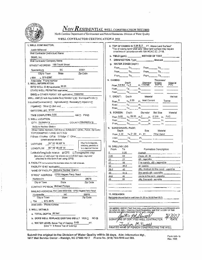
NVON RESIDENTIAL WELL CONSTRUCTION RECORD
North Carolina Department of Environment and Natural Resources- Division orWater Quality
WELL CONTRACTOR CERTIFICATION # 3439
1. WELL CONTRACTOR:
Justin Millwood
Well Contractor (Individual) Name
S&ME, Inc.
Well Contractor Company Name
STREET ADDRESS 155 Tradd Street
Spartanburg SC 29301City or Town State Zip Code
(864 )- 574-2360Area code- Phone number
2. WELL INFORMATION:SITE WELL ID #(If applicable) M-55
STATE WELL PERMIT#(If applicable)
DWQ or OTHER PERMIT #(if applicable) 70000752
WELL USE (Check Applicable Box) Monitoring M Municipal/Public o]Industrial/Commercial 0 Agricultural t] Recovery[0 Injection C1
IrrigationO Other 0 (list use)
DATE DRILLED 6/7/07
TIME COMPLETED 5:00 AM 0 PM El
3. WELL LOCATION:
CITY: Huntersville COUNTY Mecklenburg
McGuire Nuclear Station
d. TOP OF CASING IS 0.36 BLS FT. Above Land Surface*'Top of casing terminated al/or below land surface may requirea variance In accordance with 15A NCAC 2C .0118.
e, YIELD (gpm): _ METHOD OF TEST
f. DISINFECTION: Type Amount
g. WATER ZONES (depth):
From_ To _ From_ To
From_ To_ From_ To
From_ To_ From_ To
6. CASING: Thickness/Depth Diameter Weaght Material
From 0.36OLS To_5 Ft. 2 nches •cn 40 PVC
From_ To_ Ft._
From_ To_ Ft._
7. GROUT: Depth Material Method
From 0 To 2.00 Ft. Neat Cement TremieFrom To__ Ft.
From _ To - Ft.
8. SCREEN: Depth Diameter Slot Size Mlaterial
From 5,00 To 20.00 Ft2 in. 0.010 in. PVCFrom To Ft. in. In.
From_ To_ Ft. in. In.
9. SAND/GRAVEL PACK:Depth Size Material
From 4.00 To 21.00 Ft. I11 Filter Sand
From To_ Ft.
From To_ Ft._
(Street Name, Numbers, Communily, Subdivision, Lol No., Parcel, Zip Coda)TOPOGRAPHIC / LAND SETTING:
ciSlope oValley OFlat ORidge 0 Other
(check appropriate box)
LATITUDE 350 26' 00.89" N May b.- in dugrees,-linutes, seconds or
LONGITUDE 800 56' 48.48" W in a decimal format
Latitlde/longitude source: o GPS oTopographic map
(location of well must be shown on a USGS topo map andattached to this form if not using GPS)
4. FACILITY- is the name of tha business where the well Is localed.
FACILITY ID #(If applicable)_
NAME OF FACILITY McGuire Nuclear Station
STREET ADDRESS 12700 Hagers Ferry Road
Huntersville NC 28078
City or Town State Zip Code
CONTACT PERSON Michael Phillips
MAILING ADDRESS Mall Code M001 EM, 12700 Hagers Ferry Road
Huntersvllle NC 280781 City or Town State Zip Code
704 )- 875-4675
Area code - Phone number
5. WELL DETAILS:
a. TOTAL DEPTH: 20 feet
b, DOES WELL REPLACE EXISTING WELL? YES 0 NO [3
c. WATER LEVEL Below Top of Casing: 9.48 FT.(Use "+ if Above Top of Casing)
10. DRILLING LOGFrom To
0 0.25
0.25 22
22 2727 32
32 39.2
39.2 40
40 44.8
44,8 4545 50
Formation DescriptionAsphaltClayey, sill - fill
silt - saprolite
fine sandy, silt - saorolitesill - saprolite
silty, medium to fine sand - saprolito
line sandy silt - saorolite
coarse to tine sand - saprolltesilly, tine send - saprolits
11. REMARKS:Bentonite placed below well from 21.00 to 50.00 feet BLS.
I DO HEREBY CERTIFY THAT THIS WELL WAS CONSTRUCTED IN ACCORDANCE WITH15A NCAC 2C, WELL CONSTRUCTION STANDARDS, AND THAT A COPY OF THISRECORD HAS EN PROVIDED TO TH LL O ,
SIGNATYRE OF CERTIFIED WELL CONTRACTOR DATE
PRINTED NAME OF PERSON CONSTRUCTING THE WELL
Submit the original to the Division of Water Quality within 30 days. Attn: Information Mgt.,1617 Mail Servioe Center - Raleigh, NC 27699-1617 Phone No. (919) 733-7015 ext 568. Form GW-lb
Rev. 7/05

NON RESIDENTIAL WELL CONSTRUCTION RECORD
North Carolina Department of Environment and Natural Resources- Division of Water Quality
WELL CONTRACTOR CERTIFICATION # 2717
1. WELL CONTRACTOR:
Jay LittleWell Contractor (Individual) Name
S&ME, Inc.Well Contractor Company Name
STREET ADDRESS 9751 Southern Pine Boulevard
Charlotte NC 28273
City or Town State Zip Code
(704 . 523-4726Area code- Phone number
2. WELL INFORMATION:
SITE WELL ID #(If applicable) M-59
STATE WELL P ERMIT#(It applicable)
DWO or OTHER PERMIT #(if applicable) 70000752
WELL USE (Check Applicable Box) Monitoring Va Municipal/Public [D
Induslrial/Commerclat l Agrlcultural 0 Recovery0 Injection 0
IrrIgationO Other 0 (list use)
DATE DRILLED 06/01107
TIME COMPLETED 5:00 AMO PM M
3, WELL LOCATION:
CITY: Huntersville COUNTY Mecklenburg
McGulre Nuclear Station(Street Name, Numbers, Community, Subdivision, Lot No., Parcel, Zip Code)
TOPOGRAPHIC / LAND SETTING:
OSlope E]Valley OFlat nRldge 0 Other(check appropriate box)
LATITUDE 350 25' 58.34" N May be in degrees,tminutes, secornds or
LONGITUDE 80' 56' 51.54" W in a decimal forniat
Latitude/longitude source: ;aGPS oTopographic map
(location of we# must be shown on a USGS topo map andattached to this form if not using GPS)
4. FACILITY-is the name of the business where the well Is Iecaled.
FACILITY ID #(if applicable)_
NAME OF FACILITY McGuire Nuclear Station
STREET ADDRESS 12700 Hagers Ferry Road
Huntersville NC 28078
City or Town State Zip Code
CONTACT PERSON Michael Phillips
MAILING ADDRESS Mall Code MG01 EM, 12700 Hagers Ferry Rd
Huntersville NC 28078City or Town State Zip Code
704 )- 875-4675Area code. Phone number
5. WELL DETAILS:
a. TOTAL DEPTH: 36.00 t1
b, DOES WELL REPLACE EXISTING WELL? YES 0 NO Mi
c. WATER LEVEL Below Top of Casing: 24.27 FT.(Use `+` If Above Top of Casing)
d. TOP OF CASING IS 0.27 BLS FT. Above Land Surface**Top of casing terminated at/or below land surface may requirea variance In accordance with 15A NCAC 2C .0118,
a. YIELD (gpm): METHOD OF TEST
f. DISINFECTION: TypeAmount
g. WATER ZONES (depth):
From_ To From To
From To_ From_ To
From_ To_ From_ To
6. CASING: Thickness/Depth Diameter W eigh Material
From 0-11s To 2.0eIS Fs . 2 inches c u PvuFrom To_ Ft._
From_ To _ Ft._
7. GROUT: Depth Material Method
From 0 To 17.00 Ft. Neat Cement TremieFrom To Ft.
From - To_ Ft.
8. SCREEN: Depth Diameter Slot Size Material
From 21.00 To 36.00 Ft.2 in. 0.010 in. PVC
From To_ Ft. in. in.
From_ To _ Ft. in in.
9, SAND/GRAVEL PACK:Depth Size Material
From 19.00 To 37.00 Ft. Itl1 Filter Sand
From To_ Ft.
From To Ft.
10. DRILLING LOGFrom To Formation Description
0 1
1 23
23 34.334.3 36.4
36.4 37,9
37,9 85.1
Gravelslightly sandy, silly. clay - fill
silty, coarse to fine sand - saprolite
siltv, fine sand - weathered rockquonz dtodle wilth Inlaomlttni gsnmilo - parilally wonlhe0rd m00
quartz diorite, granite, meta diorite, reta quartz
disdte, and dorite -sound rock
11, REMARKS:Bentornite placed below well from 37.00 to 865.10 feet BLS.
I DO HEREBY CERTIFY THAT THIS WELL WAS CONSTRUCTED IN ACCORDANCE WITHI5A NOAC 2C. WELL CONSTRUCTION STANDARDS, AND THATA COPY OF THISRECORD HAS BEEN PROVIDED TO THE WELL OWNER.
.-- GNARE 05CERI-IFIED WELL CONTRACTORSz ; ,4z' DATE
PRINTEIDNAME OF IFERSON CONSTRUCTING THE WELL
Submit the original to the Division of Water Quality within 30 days. Attn: Information Mgt.,1617 Mall Service Center- Raleigh, NC 27699-1617 Phone No. (919) 733-7015 ext 568.
Form GW-lbRev. 7/05

NoN RESIDENTIAL WELL CONSTRUCTION RECORD
North Carolina Department of Enviroerment and Natural Resources- Division of Wter Quality
WELL CONTRACTOR CERTIFICATION # 2717
1. WELL CONTRACTOR:
Jay LittleWell Contractor (Individual) Name
S&ME, Inc.Well Contractor Company Name
STREET ADDRESS 9751 Southern Pine Boulevard
Charlotte NC 28273City or Town State Zip Code
(704 )- 523-4726Area code- Phone number
2. WELL INFORMATION:SITE WELL ID If(if applicable) M-62
STATE WELL PERMIT#(if applicable)
DWQ or OTHER PERMIT #(If applicable) 70000752
WELL USE (Check Applicable Box) Monitoring gi MunicIpal/Public 0
IndustriallCommercial [] Agricultural D Recovery C Injection 0
IrrigationD Other 0 (list use)
DATE DRILLED 05/24/07
TIME COMPLETED 5:00 AMOl PM E]
3. WELL LOCATION:CITY: Hunteraville COUNTY Mecklenourg
McGuire Nuclear Station(Street Name, Numbers, Community, Subdivision, Lol No,, Parcel, Zip Code)
TOPOGRAPHIC / LAND SETTING:OSlope DValley []FlaL 0Ridge r Other
(check appropriate box)
LATITUDE 350 25' 58.60' N May be in degrees,mnutes, seco•nds or
LONGITUDE 80' 57' 03.40' W in a decimal foinnet
Latitude/longitude soLIrce: UGPS oTopographic map(location of well must be shown on a USGS topo map and
attached to this form ff not using GPS)
4. FACILITY. is the name ot the busiRess where the waeit Is tocaed.
FACILITY ID #(if applicable)_
NAME OF FACILITY McGuire Nuclear Station
STREET ADDRESS 12700 Hagers Ferry Road
Huntersville NC 28078City or Town State Zip Code
CONTACT PERSON Michael Phillips
MAILING ADDRESS Mail Code MG01 EM, 12700 Hagers Ferry RdHuntersville NC 28078
City or Town State Zip Code
704 ). 875-4575Area code - Phone number
5. WELL DETAILS:
a. TOTAL DEPTH; 36.00 ft
b. DOES WELL REPLACE EXISTING WELL? YES [] NO El
c. WATER LEVEL Below Top of Casing: 25.37 FT.(Use "+' If Above Top of Casing)
d, TOP OF CASING IS 0.14 BLS FT. Above Land Surface**Top of casing terminated at/or below land surface may requirea variance in accordance with 15A NCAC 2C .011 B.
e, YIELD (gpm): METHOD OF TEST
f. DISINFECTION: Type Amount
g. WATER ZONES (depth):
From To From To
From _ To _ From_ To
From_ To_ From_ To
6. CASING: Thickness/Depth Diameter Weight Mterlal
FromO.140LS TO tiestc Ft. 2 inches
From To _ Ft.From - To_ Ft._
7, GROUT: Depth Material Method
From 0 To 17.00 Fl. Neat Cement Tremie
From_ To - Ft.From - To - Ft.
8, SCREEN: Depth Diameler Slot Size Material
From 21.00 To 36.00 Ft.2
in. 0.010 in. PVC
From _ To_ _ Ft. In. in.
From_ To_ Ft. in. In.
9. SANDIGRAVEL PACK:
Depth Size Material
From 19000 To36.00 Ft. #1 Filter Sand
From To Ft._
From To - Ft.
10. DRILLING LOGFrom To
0 2
2 3
3 1313 18
18 23
23 27
27 44,3
44.3 50.B
Formation DescriptionGravelConcerete
Silty fine sand with clay layers-fill
silty clay with silty sand layers-fillline sened silly weay-stretoit c
slightly candy sifti-aproliteSilty line sand - seprolitesilly fine sand- weathered rock
11. REMARKS:- Bentonite placed below well from 36 to 50.6 ft BLS.
I DO HEREBY CERTIFY THAT THIS WELL WAS CONSTRUCTED IN ACCORDANCE WITH15A NCAC 2C, WELL CONSTRUCTiON STANDARDS, AND THAT A COPYd OF THISRECORD MA8iEEN PROVIDED TO THE WELL OWNER.
r'GNA •laE F CE-R1IF[ED WELL CONTRACTOR DATE
PRINTED NAME OF PERSON CONSTRUCTING THE WELL
Submit the original to the Division of Water Quality within 30 days. Attn: Information Mgt.,1617 Mail Service Center - Raleigh, NC 27699-1617 Phone No. (919) 733-7015 ext 568.
Form GW-lbRev. 7105

NON RESIDENTIAL WELL CONSTRUCTION RECORD
North Carolina Department of Environment and Natural Resources- Division ofWaler Quality
WELL CONTRACTOR CERTIFICATION # 3439
1. WELL CONTRACTOR:
Justin MillwoodWell Contractor (Individual) Name
S&ME, Inc.Well Contractor Company Name
STREET ADDRESS 155 Tradd Street
Spartanburg SC 29301City or Town State Zip Code
(864 )- 574-2360Area code- Phone number
2. WELL INFORMATION:
SITE WELL ID #(if applicable)_ M64
STATE WELL PERMIT#(If applicable).
DWQ or OTHER PERMIT #(If applicable) 70000752
WELL USE (Check Applicable Box) Monitoring 91 Municipal/Public D
Industrial/Commercial 0 Agricultural 0 Recovery CI Injection 0
IrrigationO Other ] (list use)
DATE DRILLED 5/25/07
TIME COMPLETED 5:00 AM[] PM Li
3. WELL LOCATION:
CITY: Huntersville COUNTY Mecklenburg
McGuire Nuclear Station
d. TOP OF CASING IS 0.54 BLS FT. Above Land Surface*'Top of casing terminated ador below land surface may require
a variance In accordance with 15A NCAC 2C .0118.
a. YIELD (gpm): METHOD OF TEST
f. DISINFECTION: Type Amount
g. WATER ZONES (depth):
From_ To_ From_ To
From_ To_ From_ To
From_ To_ F rom _ To
6. CASING: Thickness/Depth Diameter Weight Material
From 0.54 LS To 13.OABLS =t, 2 Inches ch4
From_ To_ Ft._
From_ To_ Ft._
7. GROUT: Depth Material Method
From 0 To 2.00 Ft. Neat Cement Tremie
From_ To_ Ft.From- To_ Ft.
B. SCREEN: Depth Diameter Slot Size Mlaterial
From 13.00 To 28.00 Ft.2
in. 0,010 In. PVC
From- To - Ft. In. in.
From To Ft. in. in.
9. SAND/GRAVEL PACK:Depth Size Material
From 10.00 To 29.00 Ft. 41 Filter Sand
From To_ Ft._
From To_ Ft._
10. DRILLING LOGFrom To Formation Description
0 0.4 gravel
0.4 13 silly, clay - fill
13 4B.2 slightly sandy, sill-saprolite
48.2 50.1 sill with medium to line sand lenses - saprolle
11. REMARKS:- Bentonlte placed below well Irom 29.00 to 50.10 It BLS.
(Street Name, Numbers, Community, Subdivision, Lot No., Parcel, Zip Code)
TOPOGRAPHIC / LAND SETTING:
oSiope oValley CIFIat []Ridga 0 Other(check appropriate box)
LATITUDE 35' 25' 59.59" N May be in degrees, Iminmtcs, scconds or
LONGITUDE 80* 57' 01.50" W in a decimal ormiat
Latit-de/longitude source: uGPS oTopographic map
(location of well must be shown on a USGS topo map andattached to this form if not using GPS)
4. FACILITY. Is tile name t ltile business where the well Is located.
FACILITY ID #(If applicable)_
NAME OF FACILITY McGuire Nuclear Station
STREET ADDRESS 12700 Hagers Ferry Road
Huntersville NC 28078
City or Town State Zip Code
CONTACT PERSON Michael Phillips
MAILING ADDRESS Mail Code MG01EM, 12700 Hagers Ferry Rd
Huntersville NC 28078
City or Town State Zip Code
704 . 875-4675Area code - Phone number
S. WELL DETAILS:
a. TOTAL DEPTH: 28.00 it
b. DOES WELL REPLACE EXISTING WELL? YES 0 NO 0
c. WATER LEVEL Below Top of Casing: 14.04 FT.(Use "+" If Above Top of Casing)
- Bentonite seal placed 2.00 to 10.00 ft BLS.
I DO HEREBY CERTIFY THAT THIS WELL WAS CONSTRUCTED IN ACCORDANCE WITHISA NCAC 2C, WELL CONSTRUCnlON STANDARDS. AND THATA COPY OF ThISRECORD HAS BEEN PROVIDED TO THE WELL OWNER.
SIGNATURE OF CERTIFIED WELL CONTRACTOR DATE
PRINTED NAME OF PERSON CONSTRUCTING THE WELL
Submit the original to the Division of Water Quality within 30 days. Attn: Information Mgt.,1617 Mail Service Center - Raleigh, NC 27699-1617 Phone No. (919) 733-7015 ext 568.
Form GW-lbRev. 7/05

NoN RESIDENTIAL WELL CONSTRUCTION RECORDNorth Carolina Department ofEnvironment and Natural Resources- Division of Water Quality
WELL CONTRACTOR CERTIFICATION # 34389
1. WELL CONTRACTOR:
Justin MillwoodWell Contractor (Individual) Name
S&ME, Inc.Well Contractor Company Name
STREET ADDRESS 155 Tradd Street
Spartanburg SC 29301City or Town State Zip Code
864 )- 574-2360
Area code- Phone number2. WELL INFORMATION:
SITE WELL ID #(if applicable) M-66
STATE WELL PERMIT#(if applicable)_
DWQ or OTHER PERMIT #(if applicable) 70000752
WELL USE (Check Applicable Box) Monitoring M Municipal/Public 0
Industrial/Commercial 0 Agricultural 0 Recovery 0 Injection 0
IrrlgationLo Other 0 (list use)
DATE DRILLED 06/04107
TIME COMPLETED 5:00 AMO PME
3. WELL LOCATION:
CITY: Huntersvlle COUNTY Mecklenburg
McGuire Nuclear Station
(Streel Name, Numbers, Community, Subdivision, Lot No., Parcel, Zip Code)TOPOGRAPHIC / LAND SETTING:
[]Slope ElValley L-]Flat ORidge C Other(check appropriate box)
LATITUDE 35' 25' 59.54" N May be in degrees,minutes, seconds or
LONGITUDE 80° 57' 00.09" W in a decimal format
Latitude/longitude source: UGPS oTopographic map(location of well must be shown on a USGS topo map andattached to this form if not using GPS)
4. FACILITY. is the name of the business where the well Is located.
FACILITY ID #(if applicable)_
NAME OF FACILITY McGuire Nuclear Station
STREET ADDRESS 12700 Hagers Ferry Road
Huntersvllle NC 28078
City or Town State Zip Code
CONTACT PERSON Michael Phillips
MAILING ADDRESS Mail Code MG01EM, 12700 Hagars Ferry Rd
Huntersville NC 28078City or Town State Zip Code
704 )- 875-4675
Area code - Phone number
5. WELL DETAILS:
a. TOTAL DEPTH: 27.00 it
b. DOES WELL REPLACE EXISTING WELL? YES 0 NO ZI
c. WATER LEVEL Below Top of Casing: 14.76 FT.(Use "+" If Above Top of Casing)
d. TOP OF CASING IS 0.34 BLS FT, Above Land Surface''Top of casing terminated at/or below land surface may requirea variance in accordance with 15A NCAC 2C .0118.
a. YIELD {gpm): _ METHOD OF TEST
f. DISINFECTION: Type Amount
g. WATER ZONES (depth):
From_ To_ From_ To
From_ To_ From_ To
From_ To_ From_ To
6. CASING: Thickness/Depth Diameter Weight latedal
From 0.34 BLS To 12.0)aLs Ft. 2 Inches ch4 PVCFrom_ To Ft.__From_ To Ft.L _
7. GROUT: Depth Material Method
From 0 To 6.80 Ft. Neat Cement Tremie
From To Ft.
From- To_ Ft.
8. SCREEN: Depth Diameter Slot Size Material
From 12.00 To 27.00 Ft.2
in. 0.010 In. PVC
From To Ft. in. in.
From_ _ To Ft._ in. '_ n.
9. SANDIGRAVEL PACK:Depth Size Material
From 9.70 To 27.00 Ft. 91 Filter Sand
From To_ Ft._
From To_ Ft._
19, DRILLING LOGFrom To Formation Description
0 0.3 gravel
0.3 11 silty, clay inteflayered with fine sandy silt - till
11 16 clayey, silt - fill16 27 slightly clayey, fine sandy, silt - saprolite
11. REMARKS:- Bentonile seal Dlaced from 6.80 to 9.70 ft BLS.
I DO HEREBY CERTIFY THAT THIS WELL WAS CONSTRUCTED IN ACCORDANCE WITHISA NCAC 2C,YELL CONSTRUCTON STANDARDS, AND THAT A COPY OF THISRECORO HA/EEN PROVIDETO TEWELL QjER.
SIGNVURE OF CERTIFIED WELL CONTRACTOR DATE
74/ 4k i ~ oPRINTED NAME OF PERSON CONSTRUCTING THE WELL
Submit the original to the Division of Water Quality within 30 days. Attn: Information Mgt.,1617 Mail Service Center- Raleigh, NC 27699-1617 Phone No. (919) 733-7015 ext 568.
Form GW -lbRev. 7/05
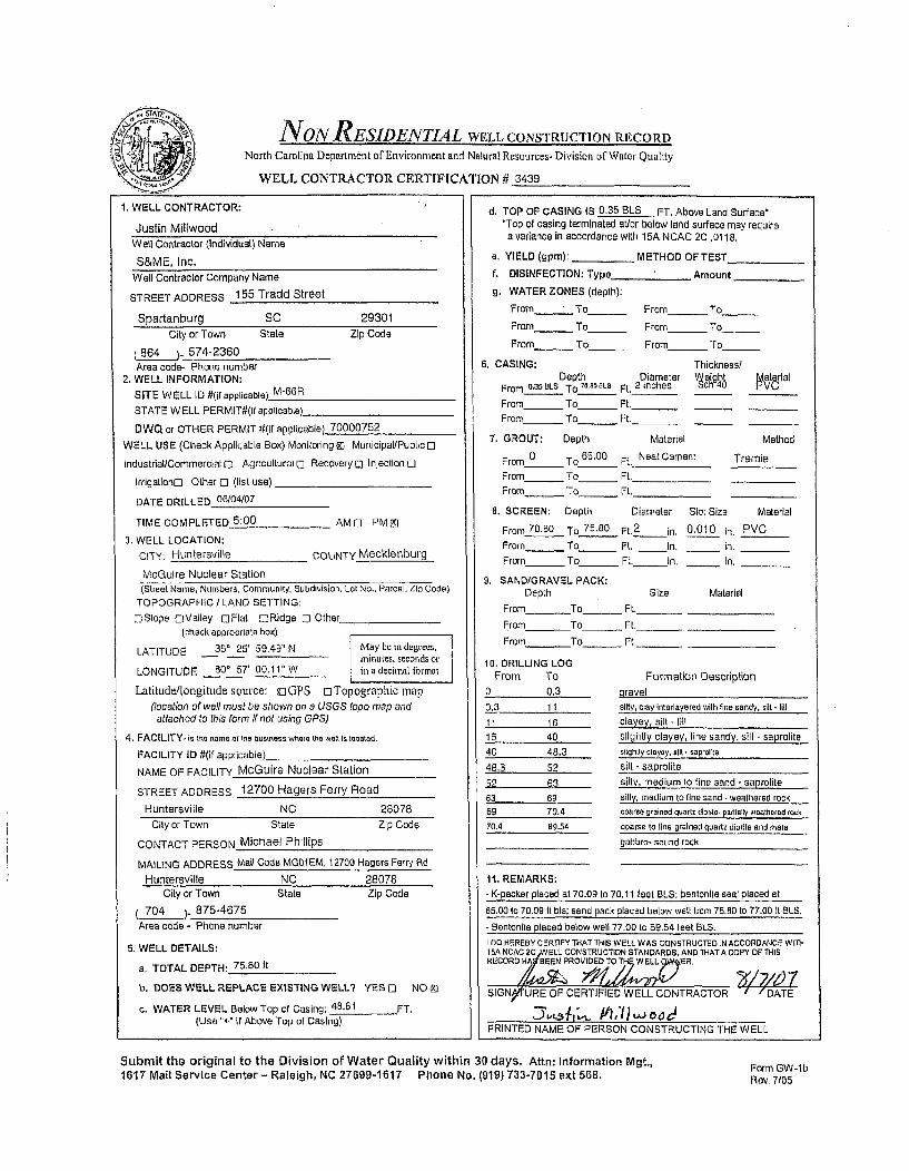
NON RESIDENTIAL WELL CONSTRUCTION RECORD
North Carolina Department ofEnvironment and Natural Resources- Division of Water Quality
WELL CONTRACTOR CERTIFICATION# I3439
1. WELL CONTRACTOR:
Justin MillwoodWell Contractor (Individual) Name
S&ME, Inc.Well Contractor Company Name
STREET ADDRESS 155 Tradd Street
Spartanburg SC 29301
City or Town State Zip Code
(864 )- 574-2360Area code- Phone number
2. WELL INFORMATION:
SITE WELL ID #(if applicable) M-66R
STATE WELL PERMIT#(If applicable).
DWQ or OTHER PERMIT #(if applicable) 70000752
WELL USE (Check Applicable Box) Moniloring 9) Municipal/Public 0
Industrial/Commerclaltl Agricultural 0 Recovery 0 Injection U
Irrigationo Other 0 (list use)
DATE DRILLED 06/04(07
TIME COMPLETED 5:00 AMD PMM
3. WELL LOCATION:
CITY: Huntersville COUNTY Mecklenburg
McGulre Nuclear Station
(Street Name, Numbers, Community, Subdivision, Lot No., Parcel, Zip Code)TOPOGRAPHIC / LAND SETTING:
OSIope oValley oFlat LiRidge D Other(check appropriate box)
LATITUDE 350 25' 59.49" N May be in degrees,minuates, seconds or
LONGITUDE 80' 57' 00.11" W in a decimal format
Latitude/tongitude source: K3GPS oTopographic map(location of wail must be shown on a USG S topo map andattached to this form if not using GPS)
4. FACILITY- is thr name of the businessv where te waiet is located.
FACILITY ID #(if applicable)
NAME OF FACILITY McGuire Nuclear Station
STREET ADDRESS 12700 Hagers Ferry Road
Huntersville NC 28078
d. TOP OF CASING IS 0.35 BLS FT. Above Land Surface'*Top of casing terminated at/or below land surface may requirea variance in accordance with 15A NCAC 2C .0118.
a. YIELD (gpm): _ METHOD OF TEST
f. DISINFECTION: Type Amount
g. WATER ZONES (depth):
From To FFrom To
From- To_ From_ To
From_ To_ From_ To
6. CASING: Thickness/Depth Diameter jeight faterial
From O.aSBLS To 70 0 1. Ft. 2 inches 4
From- To _ Ft, _
From_ To_ Ft._ _
7. GROUT: Depth Material Method
From 0 To 65,00 Ft. Neat Cement Tremie
From To Ft.From - To Ft.
8. SCREEN: Depth Diameter Slot Size Material
From 70-60 To 75.80 Ft.2
in. 0.010 in, PVCFrom To_ Ft. In. in.
From To Ft. in. In.
9. SAND/GRAVEL PACK:Depth Size Material
From To_ Ft._
From To_ Ft._
From To_ Ft._
10. DRILLING LOGFrom To
0 0.3
0.3 11
11 1616 40
40 48.3
48.3 52
52 6363 6969 70.470.4 89.54
11. REMARKS:
Formation Descriptionoravelsilty, clay intarlavered with fine sandy. slit - lill
clayey, silt - lill
slightly clayey, fine sandy, silt - saproliteslightly clayey, slit - saprolfte
silt - saprolite
silty, medium to fine sand - saprolite
silty, medium to fine sand. weathered rock
coarse grained quartz dilorile. partially weathered rock
coarse to line grained quartz diorite and meteCity or Town State Zip Code
CONTACT PERSON Michael Phillips
MAILING ADDRESS Mail Code MG01 EM, 12700 Hagers Ferry RdHuntersvllle NC 28078
gabbro- sound rock
City or Town State
704 ). 875-4675Area code - Phone number
Zip Code K-packer placed at 70.09 to 70.11 feet BLS; bentonite seal placed at
65.00 to 70.09 It bls; sand pack placed below well from 75,80 to 77.00 It BLS.
- Bentolnlte placed below well 77.00 to 69.54 teat BLS.
5. WELL DETAILS:
a. TOTAL DEPTH: 75.80 It
b. DOES WELL REPLACE EXISTING WELL? YES 0 NO M
c. WATER LEVEL Below Top of Casing: 48.61 FT.(Use "+" If Above Top of Casing)
100 HEREBY CERTIFY THAT THIS WELL WAS CONSTRUCTED IN ACCORDANCE WrInteA NCAC 2C WELL CONSTRUCTION STANDARDS, AND THAT A COPY OF THISRECORD HV'BEEN PROVIDED TO THW ELL ,ER.
SIGNYWURE OF CERTIFIED WELL CONTRACTOR I "DATE
PRINTED NAME OF PERSON CONSTRUCTING THE WELL
Submit the original to the Division of Water Quality within 30 days. Attn: Information Mgt.,1617 Mail Service Center- Raleigh, NC 27699-1617 Phone No. (919) 733-7015 ext 568.
Form GW-lbRev. 7105
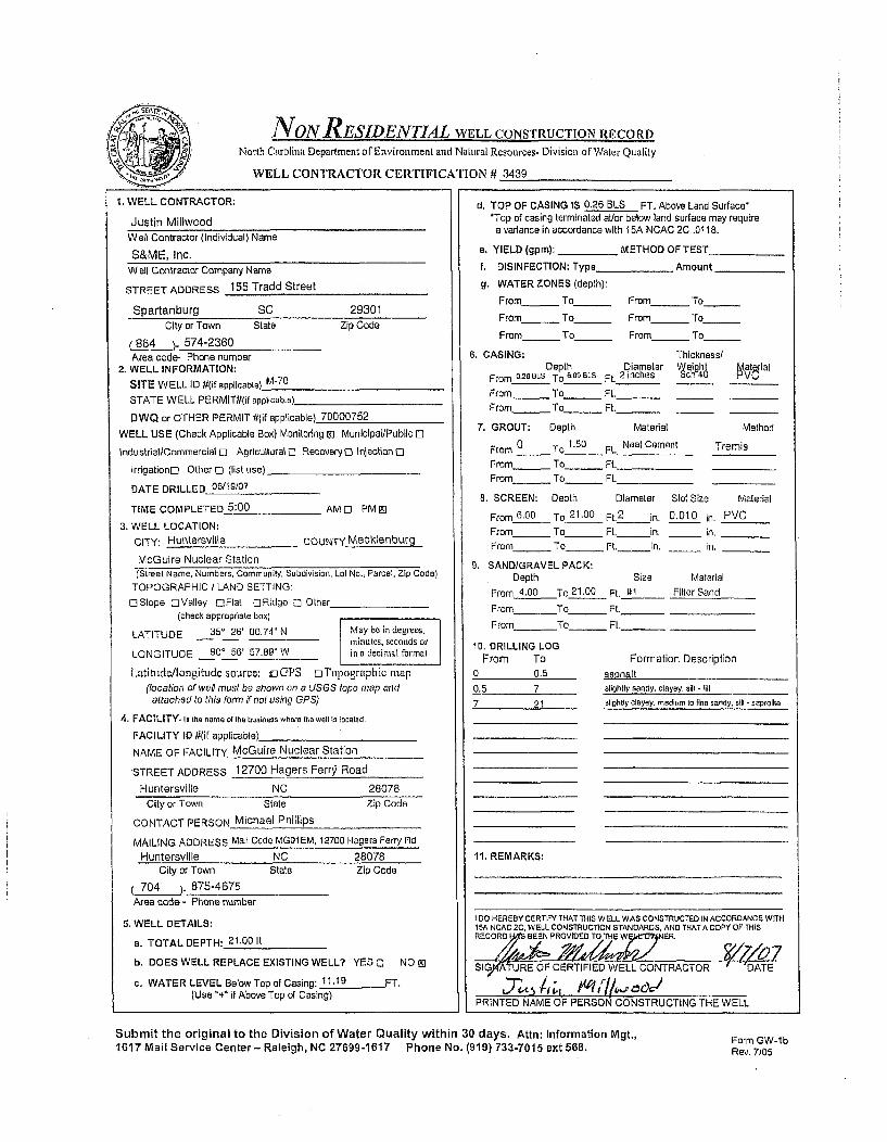
NONRESIDENTIAL WELL CONSTRUCTION RECORD
North Carolina Department of Environment and Natural Resources- Division of Water Quality
WELL CONTRACTOR CERTIFICATION # 3439
1, WELL CONTRACTOR:
Justin MillwoodWell Contractor (Individual) Name
S&ME, Inc.W ell Contractor Company Name
STREET ADDRESS 155 Tradd Street
Spartanburg SC 29301
City or Town State Zip Code
(8_64_)- 574-2360Area code- Phone number
2. WELL INFORMATION:
SITE WELL ID #(if applicable) M-70
STATE WELL PERMIT#(if applicable)
DWQ or OTHER PERMIT #(if applicable) 70000752
WELL USE (Check Applicable Box) Monitoring M1 Municipal/Public []
IndustrialtCommercial C Agricultural o RecoveryC 0njection [l
Irrigationo Olher 0 (list use)
DATE DRILLED 06/19/07
TIME COMPLETED 5:00 AMO0 PMIEl
3. WELL LOCATION:
CITY: Huntersville COUNTY Mecklenburg
McGuire Nuclear Station
d, TOP OF CASING IS 0.26 BLS FT. Above Land Surface**Top of casing terminated at/or below land surface may require
a variance in accordance with ISA NCAC 2C .0118.
a, YIELD (gpm): _ METHOD OF TEST
f. DISINFECTION: Type __ Amount
g. WATER ZONES (depth):
From_ To From - To
From- To_ From - To
From- To_ From - To
6. CASING: Thickness/Depth Diameter Weight MEatWral
From _.26ULS To 6.0 BLs Ft. 2 inches 40 HVU
From_ To_ Ft._
From - To_ Ft._
7. GROUT: Depth Material Method
From 0 To 1.50 Ft. Neat Cement TremieFrom To Ft.
From - To ___ Ft._
8. SCREEN: Depth Diameter Slot Size Material
From 6.00 To 21.00 Ft.2
in, 0.010 in. PVCFrom To Ft. in. 'In,
From - To_ Ft. in. in,
9, SAND/GRAVEL PACK:Depth Size Material
From 4.00 To 21.00 Ft. I1 Filter Sand
From To Ft._ _ _
From To_ Ft._
10. DRILLING LOGFrom To Formation Description
0 05 asphalt
0.5 7 slightly sandy, clayey, sill. lill
7 21 slightly clayey, medium to fia sandy, sill - saprolite
11, REMARKS:
(Street Name, Numbers, Community, Subdivision, Lot No., Parcel, Zip Code)
TOPOGRAPHIC / LAND SETTING:
0-SIope oValley Cl0tat [Ridge 0 Other(check appropriate box)
LATITUDE 35' 26' 00.74" N May be in degrees.mIiinutes, seconds or
LONGITUDE 80' 56' 57.89" WI in a decimal fornalt
Latitude/longitude source: oGPS oTopographic map
(iocation of well must be shown on a USGS tapo map andattached to this form if not using GPS)
4. FACILITY. Is the name o1 the business where tih well Is located.
FACILITY ID #(if applicable)_
NAME OF FACILITY McGuire Nuclear Station
'STREET ADDRESS 12700 Hagers Ferr) Road
Huntersville NC 28078
City or Town State Zip Code
CONTACT PERSON Michael Phillips
MAILING ADDRESS Mali Code MGO1EM, 12700 Hagers Ferry RdHuntersville NC 28078
City or Town State Zip Code
704 ). 875-4675Area code - Phone number
5. WELL DETAILS:
a. TOTAL DEPTH: 21.00 ft
b. DOES WELL REPLACE EXISTING WELL? YES 0 NO M
c. WATER LEVEL Below Top of Casing: 11,19 FT.(Use + if Above Top of Casing)
I DO HEREBY CERTIFY THAT THIS WELL WAS CONSTRUCTED IN ACCORDANCE wITI15A NCAC 2C, WELL CONSTRUCTION STANDARDS, AND THATACOPYOF THISRECOIG REF BEEN PROVIIED O CN TR. O519P4'((URE OF CERTIFIED WELL CONTRACTOR ' DATE
PRINTED NAME OF PERSON CONSTRUCTING THE WELL
Submit the original to the Division of Water Quality within 30 days. Attn: Information Mgt.,1617 Mail Service Center - Raleigh, NC 27699-1617 Phone No. (919) 733-7015 ext 568.
Form GW-lbRev. 7105

NON RESIDENTIAL WELL CONSTRUCTION RECORD
North Carolina Department of Environment and Natural Resources- Division of Water Quality
WELL CONTRACTOR CERTIFICATION # 3439
1. WELL CONTRACTOR:
Justin MillwoodWell Contractor (Individual) Name
S&ME, Inc.
Well Contractor Company Name
STREET ADDRESS 155 Tradd Street
Spartanburg SC 29301
City or Town State Zip Code
(864 ). 574-2360Area code- Phone number
2. WELL INFORMATION:
SITE WELL ID #(if applicable) M-70R
STATE WELL PERMITif(if applicable)
DWQ or OTHER PERMIT #(if applicable) 70000752
WELL USE (Check Applicable Box) Monitoring M] Municipal/Public E
Industrial/Commercial 0 Agricuitural 0 Recovery D Injection 0
Irrigationo Other 0 (list use)
DATE DRILLED 06/18/07
TIME COMPLETED 5:00 AMD PMEI
3. WELL LOCATION:
CITY: Huntersvllle COUNTY Mecklenburg
McGuire Nuclear Station
d. TOP OF CASING IS 0.22 BLS FT. Above Land Surface*'Top of casing terminated at/or below land surface may require
a variance in accordance with 15A NCAC 2C .0118.
a. YIELD (gpm): METHOD OF TEST
f. DISINFECTION: Type Amount
g. WATER ZONES (depth):
From_ To_ From_ To
From_ To_ From_ To
From- To_ From - To
6. CASING: Thickness/
(Street Name, Numbers, Community, Subdivision, Loi No., Parcel, Zip Code)TOPOGRAPHIC I LAND SETTING:
OSIope OValley DFlat DIRidge 0 Other(check appropriate box)
LATITUDE 35' 26' 00.73' N May be in degraes,minutes, seconds or
LONGITUDE 800 56' 57.83" W in a decimal fOlarna
Latitude/longitude source: uGPS oTopographic map(location of well must be shown on a USGS topo map and
attached to this form if not using GPS)
4. FACILITY- Is the name ef the business where the well is located,
FACILITY ID #(if applicable)_
NAME OF FACILITY McGuire Nuclear Station
STREET ADDRESS 12700 Hagers Ferry Road
Huntersvllle NC 28078
City or Town State Zip Code
CONTACT PERSON Michael Phillips
MAILING ADDRESS Mail Code MG01 EM. 12700 Hagers Ferry Rd
Huntersville NC 28078City or Town State Zip Code
704 )-875-4675Area code - Phone number
5. WELL DETAILS:
a. TOTAL DEPTH: 65.45 it
b. DOES WELL REPLACE EXISTING WELL? YES 0 NO [D
c. WATER LEVEL Below Top of Casing: 12.41 FT.(Use "+" if Above Top of Casing)
Depth Diameter •eihgh PV•t(ialFrom 0.22aLS To 55D4pBLt Ft. 2 inches
From - To - Ft._From - To_ Ft._
7. GROUT: Depth Material Method
From 0 To 13.00 Ft. Neat Cement Tremie
From To Ft.From_ To_ Ft.
8. SCREEN: Depth Diameter Slot Size Material
From 54.45 To 65.45 Ft. 2 - in. 0,010 in, PVCFrom_ To Ft. In. in.
From- To_ Ft. in. In,
9. SAND/GRAVEL PACK:Depth Size Material
From 53.50 To 65.45 Ft. 91 Filter Sand
From To_ Ft._
From To_ Ft._
10. DRILLING LOG'From To Formation Description
0 0.5 asphalt
0.5 7 slightly sandy, clayey, silt -fill
7 27 slightly clayey, medium to line sandy, silt- saprolile
27 2B.6 coarse sand - saprolite
28.6 32 slightly clayey, line sandy. silt - rapfolite
32 48 fine sandy, silt -saprolite
48 48.7 fine sandy, silt - weathered rock
48.7 65.45 silly, coarse to line sand - wealhered rock
11, REMARKS:- Bentonite seal placed from 13 to 53.50 ft BLS,
t0O HEREBY CERTIFY THAT TilS WELL WAS CONSTRUCTED IN ACCORDANCE WITH15A NCAC 2C,ý WELL CONsTRUCTION STANDARDS, AND THAT A COPY OF THISRECORD BEEN PROVIoEo TO T WE E,,, INER.
SIGpIYATURE OF CERTIFIED WELL CONTRACTOR DATE
PRINTED NAME OF PERSON CONSTRUCTING THE WELL
Submit the original to the Division of Water Quality within 30 days. Attn: Information Mgt.,1617 Mail Service Center- Raleigh, NC 27699-1617 Phone No. (919) 733-7015 ext 568. Form GW-lb
Rev. 7105

NoN RESIDENTIAL WELL CONSTRUCTION RECORD
North Carolina Department ofEnvironment and Natural Resources- Division of Water Quality
WELL CONTRACTOR CERTIFICATION 9 3439
1. WELL CONTRACTOR:
Justin MillwoodWell Contractor (Individual) Name
S&ME, Inc.
Well Contractor Company Name
STREET ADDRESS 155 Tradd Street
Spartanburg SC 29301
d. TOP OF CASING IS 0.23 BLS FT. Above Land Surface''Top of casing terminated atlor below land surface may requirea variance in accordance with 15A NCAC 2C .011 B.
City or Town State Zip Code
(864 )- 574-2360Area code- Phone number
2. WELL INFORMATION:
SITE WELL ID #(if applicable)_ M-70DR
STATE WELL PERMIT0(lf applicable)
DWQ or OTHER PERMIT #(If applicable) 70000752WELL USE (Check Applicable Box) Monitoring Z] Municipal/Public E]
Industrial/Commercial 0 Agricultural E Recovery D Injection C
IrrigationD Other 0 (list use)
DATE DRILLED 06/13/07
TIME COMPLETED 5:00 AM o PM 31
3. WELL LOCATION:
CITY: Huntersville COUNTY Mecklenburg
McGuire Nuclear Station(Street Name, Numbers, Community, Subdivision, Lot No., Parcel, Zip Code)
TOPOGRAPHIC / LAND SETTING:E]SIope oValley OFlat ORidge 0 Other
(check appropriate box)
LATITUDE 35' 26' 00,72" N May be in degeces,miniutes, seconds or
LONGITUDE 800 56' 57,78" W in a decimal rnnat
Latitude/longitude source: fjGPS oTopographic map(location of wall must be shown on a USGS lopo map and
attached to this form if not using GPS)
4. FACILITY- is the name of the business where the wall Is located.
FACILITY ID #(if applicable)
NAME OF FACILITY McGuire Nuclear Station
STREET ADDRESS 12700 Hagers Ferry Road
Huntersville NC 28078
e. YIELD (gpm): METHOD OF TEST
f. DISINFECTION: Type Amount
g, WATER ZONES (depth):
From To_ From_ To
From To From To
From_ To_ From_ To
6. CASING: Thickness/Depth Diameter Weight fa) t ial
From 0.23BLs To 7.40 BLS Ft 2 Inches hcn PVC
From_ To_ Ft._From_ To - Ft._
7. GROUT: Depth Material Method
From 0 To 7.00 Ft. Neat Cement Tremla
From_ To_ Ft.
From_ To - Ft.
8. SCREEN: Depth Diameter Slot Size Material
From 72.40 To 77.40 Ft.2
in. 0.010 in. PVCFrom To Ft. in. in.
From_ To_ Ft. in. in.
9. SAND/GRAVEL PACK:Depth Size Material
From To_ Ft._
From To_ Ft._
From To Ft._
10. DRILLING LOGFrom To
0 4
4 7
7 2727 28.6
28.6 32
32 48
48 48.7
48.7 65.5565.55 74.5
74.5 76.9
76.9 78.5
78,5 94.94
11. REMARKS:
Formation Description
asphalt with gravel baseslightly sandy, clayey, silt -fillslightly clayey, medium to line sandy, silt - saprolite
coarse sand - saprolite
slightly clayey, line sandy, silt . saprolile
fine sandy, silt - saprolite
fine sandy, silt - weathered rock
silty, coarse to fine sand -weathered rockmedium grained mats gabbro - wealhered rock
City or Town State Zip Code
CONTACT PERSON Michael Phillips
MAILING ADDRESS Mail Code MG01EM, 12700 Hagers Ferry Rd
Huntersvllle NC 28078
medium gralned quartz diorite- sound rock
medium grained meta gabbro. weathered rock
i-on d od m u alunad mala. §gabe and quanrt dla5, Sound 000
City or Town State
704 ). 875-4675Area code - Phone number
Zip Code - K-packer placed at 71.69 to 71.71 feet BLS; bentonite seal placed at
7.00 to 71.69 ft BLS; sand placed below well from 77.40 to 77.80 It BLS.
- Bentonite placed below well from 77.60 to 78.00 f1 BLS,
5. WELL DETAILS:
a. TOTAL DEPTH: 77.40 ft
b. DOES WELL REPLACE EXISTING WELL?. YES 0 NO M]
c. WATER LEVEL Below Top of Casing: 12.97 FT.(Use "+" if Above Top of Casing)
I DO HEREBY CERTIFY THAT THIS WELL WAS CONSTRUCTED IN ACCORDANCE WITH15A *CA 20EL cOSTRucTION STANDARDS. AND THAT A COPY OF THISREC RtAs BEEN PROMIC T p WNER.
SSI•/ATURE OF CERTIFIED WELL CONTRACTOR / DATE
`97-5 N1 , AV ,PRINTED NAME OF PERSON CONSTRUCTING THE WELL
Submit the original to the Division of Water Quality within 30 days, Attn: Information Mgt.,1617 Mail Service Center- Raleigh, NC 27699-1617 Phone No. (919) 733-7015 ext 568.
Form GW-lbRev, 7/05

NONR ESIDENTIAL WELL CONSTRUCTION RECORD
North Carolina Department of Environment and Natural Resources- Division or Water Quality
WELL CONTRACTOR CERTIFICATION # 2717
1. WELL CONTRACTOR:
Jay LittleWall Contractor (Individual) Name
S&ME, Inc.Well Contractor Company Name
STREET ADDRESS 9751 Southern Pine Boulevard
Charlotte NC 28273City or Town State Zip Code
704 )_ 523-4726Area code- Phone number
2. WELL INFORMATION: -
SITE WELL ID #(if applicable) M-94
STATE WELL PERMITIT(if applicable)_
DWQ or OTHER PERMIT #(If applicable) 70000752
WELL USE (Check Applicable Box) Monitoring g0 Municipal/Public E0
IndustriallCommercial 0 Agricultural 0 Recovery Injection 0
Irrigationo Other Ei (list use)
DATE DRILLED 06/28/07
TIME COMPLETED 5:00 AM 0 PM E]
3. WELL LOCATION:
CITY: Huntersvllie COUNTY Mecklenburg
McGuire Nuclear Station(Street Name, Numbers, Community, Subdivision, Lot No.. Parcel, Zip Code)
TOPOGRAPHIC / LAND SETTING:
-Slope r-Valley DFlat ORidge [I Other(check appropriate box)
LATITUDE 350 25ý 53.57" N May be in degrees,minutes, seconds or
LONGITUDE 80* 5T 06,09" W in u decimal tbrmnat
Latintde/Iongiwtde source: y:GPS oTopographic map(location of well must be shown on a USGS topo map and
attached to this form if not using GPS)
4. FACILITY-is the name of the business where the well Is located,
FACILITY ID #(if applicable)_
NAME OF FACILITY McGuire Nuclear Station
STREET ADDRESS 12700 Hagers Ferry Road
Huntersvllle NC 28078
City or Town State Zip Code
CONTACT PERSON Michael Phillips
MAILING ADDRESS Mall Code MG01 EM, 12700 Hagers Ferry Rd
Huntersville NC 28078City or Town State Zip Code
704 ). 875-4675
Area code - Phone number
5. WELL DETAILS:
a, TOTAL DEPTH: 44.10 1t
b. DOES WELL REPLACE EXISTING WELL? YES El NO gi
c. WATER LEVEL Below Top of Casing: 35.43 FT.(Use "+" if Above Top of Casing)
d, TOP OF CASING IS 2.96 FT. Above Land Surface-*Top of casing terminated a@lor below land surface may requirea variance in accordance with 15A NCAC 2C .0118.
a. YIELD (gpm): _ METHOD OF TEST
f, DISINFECTION: Type Amount
g. WATER ZONES (depth):
From_ To_ From_ To
From- To - From_ To
From_ To_ From_ _ To
6, CASING: Thickness/Depth Diameter Weight Material
F rom 2.08AL e T o 2 ,-.(__BLs F t. 2 Inches T mc nl4 u -'V t
From_ To_ Ft._ _
From_ To_ Ft._ _
7. GROUT: Depth Material Method
From 0 To 24.00 Ft. Neat Cement Tremie
From To Ft.
From_ To ___ Ft.
8. SCREEN: Depth Diameter Slot Size Material
From 29.10 To 44.10 Ft.2
In. 0,010 in. PVC
From To Ft. in. In.From_ To_ Ft. in. in.
g. SAND/GRAVEL PACK:
Depth Size Material
From 27.00 To 44.10 Ft. t1t Filter Sand
From To_ Ft._
From To _ Ft._
10. DRILLING LOGFrom To Formation Description
0 9
9 14
14 1919 , 19.2
19.2 23
23 29
29 35.535.5 44.1
11. REMARKS:
fine sandv. silt - alluvium
clayey, silt - alluvium
silty, clay - alluviumfine sandy, silt - alluviummedium to line sandy, clay - alluvium
slightly clayey, fine sandy, silt - saprolite
coarse to fine sandy, silt - saprolite
line sandy, silt - saprollte
I DO HEREBY CERTIFY THAT THIS WELL WAS CONSTRUCTED IN ACCORDANCE W ITHt5A NCAC 2C, WELL CONSTRUCTtON STANDARDS, AND THAT A COPY OF THISRECORD HAS.BEEN PROVIDED TO THE WELL OWNER.
_S)9AT.UE OF CERTIFIED WELL CONTRACTOR
1:-7.: Z,4 ',;Z471DATE
I PRINTED NME OF'PER'SON CONSTRUCTING THE WELL
Submit the original to the Division of Water Quality within 30 days, Attn: Information Mgt,,1617 Mail Service Center - Raleigh, NC 27699.1617 Phone No. (919) 733-7015 ext 568.
Form GW-1bRev. 7/05

NON RESIDENTIAL WELL CONSTRUCTION RECORD
North Carolina Department of Enviroment and Natural Resouroes- Division of Water Quality
WELL CONTRACTOR CERTIFICATION # 3439
1. WELL CONTRACTOR;
Justin MillwoodWell Contractor (Individual) Name
S&ME, Inc.Well Contractor Company Name
STREET ADDRESS 155 Tradd Street
Spartanburg SC 29301City or Town State Zip Code
8684 ). 574-2360Area code- Phone number
2. WELL INFORMATION:
SITE WELL ID #(If applicable) M-104DR
STATE WELL PERMIT#(if applicable)
DWQ or OTHER PERMIT #(If applicable) 70000752
WELL USE (Check Applicable Box) Monitoring MI MunicipallPublic 0
Industrial/Commercial[] Agricultural 0 Recovery0 Injection 0
Irrigationo Other 0 (list use)
DATE DRILLED 07/10107
TIME COMPLETED 5:00 AM[] PMZI
3. WELL LOCATION:
CITY: Huntersville COUNTY Mecklenburg
McGuire Nuclear Station(Street Name, Numbers, Community, Subdivision, Lot No,, Parcel, ZIp Code)
TOPOGRAPHIC / LAND SETTING:
OSlope OValley JFlal ORidge E] Other(check appropriate box)
LATITUDE 35 25' 51,88" N May be in degrees,Ininutes, secatis or
LONGITUDE 80 57' 16.24" W in a decimal ri•nra
Latitude/longitude source: GOPS oTopographic map(location of well must be shown on a USGS topo map andattached to this form if not using GPS)
4, FACILITY- is the name of Viae businees where the weil is located.
FACILITY ID #(it applicable)_
NAME OF FACILITY McGuire Nuclear Station
STREET ADDRESS 12700 Hagers Ferry Road
Huntersville NC 28078City or Town State Zip Code
CONTACT PERSON Michael Phillips
MAILING ADDRESS Mail Code MG01 EM, 12700 Hagers Ferry Rd
Huntersville NC 28078City or Town State Zip Code
704 ), 875-4675
Area code - Phone number
5. WELL DETAILS:
a. TOTAL DEPTH: 76.00 It
b, DOES WELL REPLACE EXISTING WELL? YES [E NO 91
c. WATER LEVEL Below Top of Casing: 42.51 FT,(Use "+' if Above Top of Casing)
d. TOP OF CASING IS 3.02 FT. Above Land Surface-*Top of casing terminated at/or below land surface may require
a variance in accordance with 15A NCAC 2C .0118.
e, YIELD (gpm): METHOD OF TEST
f. DISINFECTION: Type Amount
g. WATER ZONES (depth):
From- To _ From_ To
From_ To _ From_ To
From_ To _ From_ To
6. CASING: Thickness/Depth Diameter Weght I.lrlal
From 3.52 ALS To. .lS Ft. 2 inches T 46
From - To _ Ft._From_ To _ Ft._
7. GROUT: Depth Material Method
From - To_ Ft.
From_ To_ Ft.From_ To_ Ft.
8. SCREEN: Depth Diameter Slot Size Material
From 71.00 To_76.00 Ft. 2 in. 0.010 in. PVC
From_ To Ft. in. in.
From_ To_ Ft. in. in.
9. SANDIGRAVEL PACK:
Depth Size Material
From To Ft.
From To_ FI.
From To_ Ft.
10, DRILLING LOGFrom To Formation Description
0 8 medium to fine sandy silty clay
8 36,70 silty fine to med/coarse sand
36.70 refusal to roller cone drill bit36.70 80.28 wealhered and sound rock -coarse grained granlet
11. REMARKS:
- K-packer placed at 70.29 to 70.31 ft BLS; bentonite seal placed at
0 to 70.29 ft BLS: sand/tflter pack placed below wall from 76.00 to 77.50 It ELS.
- Bentonite placed below well from 77.50 to 80.28 feet BLS.
I DO HEREBY CERTIFY THAT THIS WELL WAS CONSTRUCTED IN ACCORDANCE WITH
'5A NOACa W WELL CONSTRUCTtON STANDý AND 7HATA COPY 0P THISRECO Rr AsEEN PROVIDED TO ThE L[1 0 ER.
SI ATURE OF CERTIFIED WELL CONTRACTOR {DATE7b#-
PRINTED NAME OF PERSON CONSTRUCTING THE WELL
Submit the original to the Division of Water Quality within 30 days. Attn: Information Mgt.,1617 Mail Service Center- Raleigh, NC 27699-1617 Phone No. (919) 733-7015 ext 568. Form GW-Ib
Rev. 7/05

lkS&ME
August 6, 2007
North Carolina Department of Environment and Natural ResourcesDivision of Water Quality1617 Mail Service CenterRaleigh, North Carolina 27699-1617
ATTN: Information Management
Reference: NON-RESIDENTIAL WELL CONSTRUCTION RECORDS - SUBMITTAL #4McGUIRE NUCLEAR STATION12700 Hagers Ferry RoadHuntersville, North CarolinaS&ME Project No. 1264-06-724
Ladies and Gentlemen:
On behalf of Duke Energy, S&ME, Inc. (S&ME) is submitting the enclosed completed and signed Non-Residential Well Construction Records for the following fifteen (15) groundwater monitoring wellsinstalled at the McGuire Nuclear Station (MNS) site:
* M-48 • M-55 0 M-66 • M-70DR* M-48R * M-59 0 M-66R 0 M-94* M-48DR • M-62 a M-70 * M- 104DR.° M-53 * M-64 9 M-70R
Duke Energy is voluntarily installing groundwater monitoring wells at MNS as part of a site-widehydrogeologic evaluation. S&ME will continue to submit these Non-Residential Well ConstructionRecords on a periodic basis as well installations are completed, this being the fourth submittal (i.e.,Submittal #4).
On behalf of Duke Energy, S&ME thanks you for your receipt of these records. Should you have anyquestions or need additional information, please contact us.
Sincerely,S&ME, Inc.
Mary Be• ClnEIT strong, P..
Staff Professional S r ineer/Project Director
enclosures
cc: Messrs. Steve LeRoy, Ed Sullivan, Tim Hunsucker; Duke Energy
SAENVIROPA2006\J 264 Projects\6406724 McGuire Nuclear Groundwater StudyWCDENR Well Recordsnccdenr well records sut ittal 4.doc
S&ME, INC. / 155 Tradd Street / Spartanburg, SC 29301 / p 864.574.2360 f 864.576.87301 Marcus Drive, Suite 301 / Greenville, SC 29615 /p 864-232-8987 / www.smeinc.com
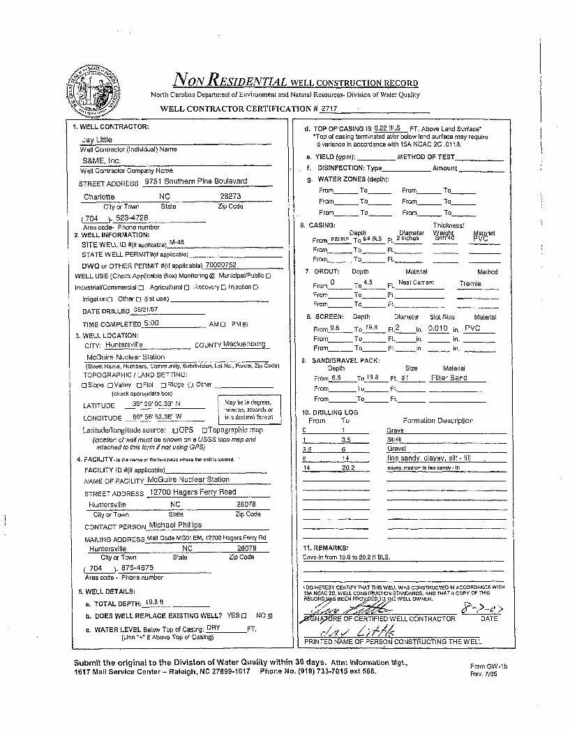
NON RESIDENTIAL WELL CONSTRUCTION RECORDNorth Carolina Department of Environment and Natural Resources- Division of Water Quality
WELL CONTRACTOR CERTIFICATION # 2717
1. WELL CONTRACTOR:
Jay LittleWell Contractor (Individual) Name
S&ME, Inc.Well Contractor Company Name
STREET ADDRESS 9751 Southern Pine Boulevard
Charlotte NC 213273City or Town Stale Zip Code
(704 -523-4726Area code- Phone number
2. WELL INFORMATION:
SITE WELL ID #(It applicable) M-48
STATE W ELL PERMIT#(i/ applicable)
DWQ or OTHER PERMIT #(if applicable) 70000752
WELL USE (Check Applicable Box) Monitoring (9 Munlclpal/Public Cl
Industrial/Commercial ] Agricultural D Recovery 0 Injection 0
Irrigationrl Other Ci (list use)
DATE DRILLED 06/21/07
TIME COMPLETED 5:00 AMO PM Ey
3. WELL LOCATION:
CITY: Huntersville COUNTY Macklenburg
McGuire Nuclear Station(street Name. Numbers, Community, Subdivision, Lot No., Parcel, Zip Code)
TOPOGRAPHIC / LAND SETTING:
O]Slope CValley 0 Flat CRidge 0 Other_
(check appropriate box)
LATITUDE 35' 26' 00.33 N May be in degrees,Liinutes, seconds orLONGITUDE B0° 56' 52.36" W in a decimnal format
Latitude/longitudesource: g GPS oTopographic map(location of well must be shown on a USGS topo map andattached to this form if not using GPS)
4. FACILITY. is the name of the business where 1he well Is socaled,
FACILITY ID #(if applicable)
NAME OF FACILITY McGuire Nuclear Station
STREET ADDRESS 12700 Hagers Ferry Road
Huntersville NC 28078City or Town State Zip Code
CONTACT PERSON Michael Phillips
MAILING ADDRESS Mall Code MG01 EM, 12700 Hagers Ferry Rd
Huntersvllle NC 28078City or Town State Zip Code
704 )- 875-4675Area code - Phone number
5. WELL DETAILS:
a. TOTAL DEPTH: 19.8 ft
b. DOES WELL REPLACE EXISTING WELL? YES 0 NO MJ
c, WATER LEVEL Below Top of Casing: DRY FT.(Use "+" If Above Top of Casing)
d. TOP OF CASING IS 0.22 BLS FT. Above Land Surface**Top of casing terminated at/or below land surface may require
6 variance In accordance with 15A NCAC 2C .0118.
e. YIELD (gpm): METHOD OF TEST
f. DISINFECTION: Type Amount
g. WATER ZONES (depth):
From_ To_ From To
From_ To_ From_ To
From_ To_ From_ To
6. CASING: Thickness/Depth Diameter WeigM PMaterial
From _.22 ULS TO 9. BLS Ft. 2 inches
From To_ Ft. -
From_ To_ Ft._
7. GROUT: Depth Material Method
From 0 To 4.5 Ft. Neat Cement Tremie
From - To_ Ft.
From_ To_ Ft.
8, SCREEN: Depth Diameter Slot Size Material
From 9.8 To 19.8 Ft2
in. 0.010 in. PVC
From To Fl. in. In.
From_ _ To Ft. in. In.
9. SAND/GRAVEL PACK:Depth Size Material
From 6.5 To 19.8 Ft. #1 Filter Sand
From To_ Ft._
From To_ Ft._
10. DRILLING LOGFrom To Formation Description
0 11 3.5
3.5 6
6 14
14 20.2
11. REMARKS:
Cave-In from 19.8 to 20.2 it EL
GravelSilt-fill
Gravel
tine sandy, clavey, silt - tillclayey. medium to lire sandy - hI]I
1 00 HEREBY CERTIFY THAt THIS WELL WAS CONarSRUCTSO IN ACCORDANCE W TH15A NCAC 20, WELL CONSTRUCTION STANDARDS. AND THATA COPY OF THISRECORPMS BEEN PROVjDED70 THE WELL OWNER.
,X"N RE OF CERTIFIED WELL CONTRACTOR DATE
PRINTED NAME OF PERSON CONSTRUCTING THE WELL
Submit the original to the Division of Water Quality within 30 days. Attn: Information Mgt.,1617 Mail Service Center - Raleigh, NC 27699-1617 Phone No. (919) 733-7015 ext 568.
Form GW-1 bRev. 7/05
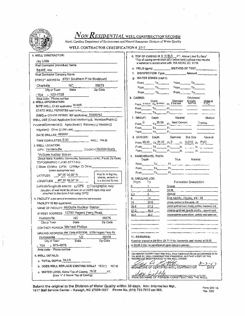
NONRESIDENTIAL WELL CONSTRUCTION RECORDNorth Carolina Department of Environment and Natural Resources- Division or Water Quality
WELL CONTRACTOR CERTIFICATION # 2717
1. WELL CONTRACTOR:
Jay LittleWell Contractor (Individual) Name
S&ME, Inc.Well Contractor Company Name
STREET ADDRESS 9751 Southern Pine Boulevard
Charlotte NC 28273City or Town State Zip Code
(704 )- 523-4726Area code- Phone number
2. WELL INFORMATION:SITE WELL ID #{it applicable) M-48R
STATE WELL PERMiT#/f applicable).
DWQ or OTHER PERMIT #(if applicable) 70000752
WELL USE (Check Applicable Box) Monitoring (K Municipal/Public El
Industriai/CommercialoE Agricultural El Recovery o Injection [3
irrigation[] Other El (list use)
DATE DRILLED 06/20/07
TIME COMPLETED 5:00 AMD PMI
3, WELL LOCATION:
CITY: Huntersvllle COUNTY Meclkenburg
McGuire Nuclear Station(Street Name, Numbers, Communily. Subdivsion, Lot No., Parcel, Zip Code)
TOPOGRAPHIC / LAND SETTING:
ciSlope E]Vailey 0Flat ORidge El Other(check appropriate box)
LATITUDE 35' 26' 00.30" N May bc in degrees,minutes, seconds or
LONGITUDE 80' 56' 52.34" W in a decimul format
Latitude/longitude source: o,_GPS ciTopographic map(location of well must be shown on a USGS topo map and
attached to this form if not using GPS)
4. FACILITY- is tui name of tha businass wha re Ith well It located.
FACILITY ID A(il applicable)
NAME OF FACILITY McGuire Nuclear Station
STREET ADDRESS 12700 Hagers Ferry Road
Huntersville NC 28078
d. TOP OF CASING IS 0.13 BLS FT. Above Land Surface''Top of casing terminated al/or below land surface may requirea variance in accordance with 15A NCAC 2C .0118.
a. YIELD (gpm): METHOD OF TEST
f. DISINFECTION; Type Amount
g. WATER ZONES (depth):
From- To_ From - To
From - To_ From - To
From- To_ From To
6. CASING: Thickness/Depth Diameter Weight P11ial
From 0.13OLS To t2g.tG5LS Ft. 2 inches P0h4U
From_ To_ Ft. _ _
From_ To_ Ft. _ _
7. GROUT: Depth Material Method
From 0 To 25.00 Ft. Neat Cement Tremie
From To Ft.
From- To Ft.
8. SCREEN: Depth Diameter Slot Size Material
From 29.40 To 34.40 Ft.2 in. 0.010 in, PVC
From To_ _ Ft. in. _ in.
From_ To Ft. in. _ in.
9. SAND/GRAVEL PACK:Depth Size Material
From To Ft._
From To Ft. _
From To_ Ft._
10. DRILLING LOGFrom To Formation Description
0 1 Gravel
1 3.5 Sill-fill3.5 6 Gravel
6 14 fine sandy, clayey, silt - fill
14 20.6 clayey, medium to (Ine sandy - tl
20.6 27.3 coarse-grained quartz diorite- partially wealitered rack
27.3 30.2 coarse-grained quartz diorite - sound rock
30,2 . 5,2 coarse-grained quartz diodl1 - partially weathered rock
11, REMARKS:
K-packer placed at 28.69 to 28.71 It bts; bentonite seal placed at 25,00
City or Town State Zip Code
CONTACT PERSON Michael Phillips
MAILING ADDRESS Mail Code MGO1 EM, 12700 Hagets Ferry Pd
Huntersville NC 28078City or Town State Zip Code
704 )- 875-4675
Area code - Phone number
5. WELL DETAILS:
a. TOTAL DEPTH: 34.4 it
b. DOES WELL REPLACE EXISTING WELL? YES El NO M
c. WATER LEVEL Below Top of Casing: 19.32 FT,(Use "+" If Above Top of Casing)
to 28.69 it bls; no sand/gravel pack below k-packer.
I DO HEREBY CERTIFY THAT THIS WELL WAS CONSTRUCTED IN ACCORDANCE WITH15A NCAC 2c, WELL CONSTRUC"TON STANDARDS, AND THAT A COPY OF THISRECORD S BEEN PROVIDED TO THE WELL OWNER.
,SIGNATURE OF CERTIFIED WELL CONTRACTOR DATE
PRINTE6 NAME OF PERSON CONSTRUCTING THE WELL
Submit the original to the Division of Water Quality within 30 days, Attn: Information Mgt.,1617 Mail Service Center- Raleigh, NC 27699-1617 Phone No. (919) 733-7015 ext 568.
Form GW-IbRev. 7/05

NON RESIDENTIAL WELL CONSTRUCTION RECORDNorth Carolina Department of Envirotnment and Natural Resources- Division of Water Quality
WELL CONTRACTOR CERTIFICATION # 2717
1. WELL CONTRACTOR:
Jay LittleWell Contractor (Individual) Name
S&ME, Inc.W ell Contractor Company Name
STREET ADDRESS 9751 Southern Pine Boulevard
Charlotte NC 28273
City or Town State Zip Code
(704 )- 523-4726Area code- Phone number
2, WELL INFORMATION:SITE WELL ID #(If applicable) M-48DRSTATE WELL PERMIT#(if applicable)
DWQ or OTHER PERMIT #(if applicable) 70000752
WELL USE (Check Applicable Box) Monitoring M Municipal/Public 0
Industrial/Commercial 0 Agricultural 0 RecoveryC Injection El
Irrigationol Other 0 (list use)
DATE DRILLED D0618/07
TIME COMPLETED 5:00 AM [3 PM 0I
3. WELL LOCATION:CITY: Huntersville COUNTY Mecklenburg
McGuire Nuclear Station(Street Name, Numbers, Community, Subdivision, Lot No., Parcal, Zip Code)
TOPOGRAPHIC / LAND SETTING:3Slope.OValley FIRMat _IRidge 00 lher_
(check appropriate box)
LATITUDE 35' 26' 00.31" N May be in degrees,minules, secands Or
LONGITUDE 800 56' 52.40" W in s decimal f01or1a
Latitude/longittude source: CGPS oTopographic map(location of well must be shown on a USGS topo map andattached to this form if not using GPS)
4. FACILITY- is the name of Iia business whare the wall is located.
FACILITY ID0 1(if applicable)_
NAME OF FACILITY McGuire Nuclear Station
STREET ADDRESS 12700 Hagers Ferry Road
Huntersvllle NC 28078City or Town State Zip Code
CONTACT PERSON Michael Phillips
MAILING ADDRESS Mali Code MGO1 EM, 12700 Hagers Ferry Rd
Huntersville NC 28078City or Town State Zip Code
704 )- 875-4675Area code - Phone number
5. WELL DETAILS:
a. TOTAL DEPTH: 89.00 It
b. DOES WELL REPLACE EXISTING WELL? YES 0 NO 91
c. WATER LEVEL Below Top of Casing: 20.42 FT.(Use "+" If Above Top of Casing)
d. TOP OF CASING IS 0.29 BLS FT. Above Land Surface**Top of casing terminated at/or below land surface may require
a variance in accordance with 15A NCAC 2C .0118.
a. YIELD (gpm): _...... METHOD OF TEST
f. DISINFECTION: Type _ Amount
g. WATER ZONES (depth):
From- To_ From_ To
From_ To_ From_ To
From_ To_ From - To
6. CASING: Thickness/Depth Diameter `1 eiqh( Material
From 0.25BLS To 70.00 BeL Ft. 2 inches 4
From_ To - Ft._From_ To _ Ft._
7. GROUT: Depth Material Method
From 0 To 75.00 Ft. Neat Cement Tremie
From To Ft.From_ To__ Ft,
8. SCREEN: Depth Diameter Slot Size Material
From 79,00 To 89.00 Ft.2
in, 0,010 in. PVC
From___ To____ Ft. in. _ in.
From_ To _ Ft. in, _ in.
9, SAND/GRAVEL PACK:Depth Size Material
From To Ft.
From To Ft.
From To_ Ft._
10. DRILLING LOGFrom To Formation Description
0 1 Gravel
1 3.5 Sill-till
3.5 6 Gravel6 14 fine sandy, clayey, silt - fill
14 21.6 clayey, medium to line sand . ill
21.6 90.3 coarse grained to fine grained quartz dorite,granite, and mete gabbro
11. REMARKS:- K-packer placed at 78.09 to 78.11 It BLS, bentonite seal placed at 75.00
to 78.09 It bls; no sand/gravel pack below k-packer.
- Cave-In from 89.00 to 90.30 It BLS.O0 HEREBY CERTIFY THAT THIS WELL WAS CONSTRUCTED IN ACCORDANCE WITH
15A NCAC 2C, WELL CONSTRUCTION STANDARDS, AND THATA COPY OF THISRECORD.AS BEEN PRO0IDE0 TO THE WELL OWNER.
/SIGN9IIURE OF CERTIFIED WELL CONTRACTOR DATE
PRINTED NAME OF PERSON CONSTRUCTING THE WELL
Submit the original to the Division of Water Quality within 30 days. Attn: Information Mgt.,1617 Mail Service Center - Raleigh, NC 27699-1617 Phone No. (919) 733-7015 ext 568.
Form GW-lbRev. 7/05

NoN RESIDENTIAL WELL CONSTRUCTION RECORDNorth Carolina Department of Environment and Natural Resources. Division of Water Quality
WELL CONTRACTOR CERTIFICATION # 2717
1. WELL CONTRACTOR:
Jay LittleWell Contractor (Individual) Name
S&ME, Inc.W ell Contractor Company Name
STREET ADDRESS 9751 Southern Pine Boulevard
Charlotte NC 28273City or Town State Zip Code
(70L4 ). 523-4726
Area code- Phone number2. WELL INFORMATION:
SITE WELL ID #(1f applicable) M-53
STATE WELL PERMIT#(if applicable)_
DWQ or OTHER PERMIT #(if applicable) 70000752
WELL USE (Check Applicable Box) Monitoring Ml Municipal/Public 0
Industrial/Commercial 0 Agricultural ] Recovery 0 Injection El
trrigatlono Other C1 (list use)
DATE DRILLED 05/29/07
TIME COMPLETED 5:00 AMD PMIE
3. WELL LOCATION:
CITY: Huntersvllle COUNTY Mecklenburg
McGuire Nuclear Station
d. TOP OF CASING IS 0.25 8LS FT. Above Land Surface**Top of casing terminated at/or below land surface may require
a variance In accordance with 15A NCAC 2C .0118.
e. YIELD (gpm): _ METHOD OF TEST_
f. DISINFECTION: Typa _ Amount
9. WATER ZONES (depth);
Fromm To _ From_ To
From_ To _ From_ To
From____ To_ From_ To
6, CASING: Thickness/Depth Diameter elght Material
From 5,a5 5LS To 8,00 BLS Ft. 2 inches P08From- To_ Ft._ _
From- To - Fl._ _
7. GROUT: Depth Material MethodFrom 0 To 4.00 Ft. Neat Cement Tremie
From To Ft.
From _ To _ Ft.
8. SCREEN: Depth Diameter Slot Size Material
From 8.00 To 23.00 Ft.2
in. 0,010 in. PVC
From To Ft. In. In.
From _ To _ Ft._ in. in.
9. SAND/GRAVEL PACK;Depth Size Material
From 6.00 To 23.00 Ft. It 1 Filter Sand
From To_ Ft._
From To_ Ft._
10. DRILLING LOGFrom To Formation Description
0 1 Asphalt
1 13 fine sandy, silty, clay -possible fill
13 27 fine sandy, silt - saprollte27 33.7 silty, fine sand - saprolite
33.7 43.2 silty. medium Io line sand. sapfollte
43,2 48.2 silty, coarse to fine sand - weathered rock
48.2 50 fine sandy, silt - weathered rock
11, REMARKS:
Bennonite placed below well from 23.00 to 50.00 feet GLS.
(Street Name, Numbers, Community, Subdivision, Lot No., Parcel, Zip Code)
TOPOGRAPHIC I LAND SETTING:
DSlope OValley ElFlat ,ORidge El Other(check appropriate box)
LATITUDE 350 26' 02.07" N May be in degrees,miniutes, seconds or
LONGITUDE 80' 56' 53.16" W in a decimal tbrmat
Latitude/longitude source: riGPS oTopographic map(location of well must be shown on a USGS topo map and
attached to this form if not using GPS)
4. FACILITY- Is the name of lie business where he well Is located.
FACILITY ID #(if applicable)
NAME OF FACILITY McGuire Nuclear Station
STREET ADDRESS 12700 Hagers Ferry Road
Huntersville NC 28078
City or Town State Zip Code
CONTACT PERSON Michael Phillips
MAILING ADDRESS Mall Code MGO1 EM, 12700 Hagers Ferry Rd
Huntersville NC 28078City or Town State
704 )- 875-4675Area code - Phone number
Zip Code
5. WELL DETAILS:
a. TOTAL DEPTH. 23.00 if
b. DOES WELL REPLACE EXISTING WELL? YES El NO mt
c. WATER LEVEL Below Top of Casing: 14.52 FT.(Use "+" it Above Top of Casing)
1 00 HEREBY CERTIFY THAT THIS WELL WAS CONSTRUCTED IN ACCORDANCE WITH15A NCAC 2C, WELL CONSTRUCTION STANDARDS, AND THATA COPY OF THIS
RECO7D.aAO BEEN PROVIDED TO THE WELL OWNER.
SIGNAT•1Y9E OF CERTIFIED WELL CONTRACTOR D
PRINTED N•AME OF PERSON CONSTRUCTING THE WELL
ATE
Submit the original to the Division of Water Quality within 30 days. Attn: Information Mgt,,1617 Mail Service Center- Raleigh, NC 27699-1617 Phone No. (919) 733-7015 ext 568. Form GW-lb
Rev, 7/05

NONRESIDENTIAL WELL CONSTRUCTION RECORD
North Carolina Department of Environment and Natural Resources- Division of Water Quality
WELL CONTRACTOR CERTIFICATION # 3439
1. WELL CONTRACTOR:
Justin Millwood
Well Contractor (Individual) Name
S&ME, Inc.
Well Contractor Company Name
STREET ADDRESS 155 Tradd Street
Spartanburg SC 29301
CIty or Town State Zip Code
(864 )- 574-2360Area code- Phone number
2. WELL INFORMATION:SITE WELL ID #(If applicable) M-55
STATE WELL PERMIT#(if applicable)_
DWQ or OTHER PERMIT #l(if applicable) 70000752
WELL USE (Check Applicable Box) Monitoring 91 Municipal/Public El
Industrial/CommercialI] AgriculturaloE Recovery [3 Injection El
Irrigationfl Other El (list use)
DATE DRILLED 6/7/07
TIME COMPLETED 5:00 AM O] PM El
3. WELL LOCATION:
CITY: Huntersville COUNTY Mecklenburg
McGuire Nuclear Station(Street Name, Numbers, Community, Subdivision, Lot No., Parcel, Zip Code)
TOPOGRAPHIC / LAND SETTING:ESiope C]Valley DFleat ORidge E Other
(check appropriate box)
LATITUDE 351 26 00.89" N May be in degrees,minutes, seconds or
LONGITUDE 80' 56' 48.48" W an a decimal format
Latitude/longitude source: I[GPS EiTopographic map(location of well must be shown on a USGS topo map andattached to this form if not using GPS)
4. FACILITY- is the name of the business where the well is eorated.
FACILITY ID #(if applicable)_
NAME OF FACILITY MeGuire Nuclear Station
STREET ADDRESS 12700 Hagers Ferry Road
Huntersville NC 28078
City or Town State Zip Code
CONTACT PERSON Michael Phillips
MAILING ADDRESS Malt Code MG01 EM, 12700 Hagers Ferry Road
Huntersvllle NC 28078City or Town State Zip Code
704 ). 875-4675Area code - Phone number
5. WELL DETAILS:
a. TOTAL DEPTH: 20 feet
b. DOES WELL REPLACE EXISTING WELL? YES [E NO In
c. WATER LEVEL Below Top of Casing: 9.48 FT.(Use "+" If Above Top of Casing)
cd, TOP OF CASING IS 0.36 BLS FT. Above Land Surface'Top of casing terminated at/or below land surface may require
a variance In accordance with 15A NCAC 2C .0118.
e. YIELD (gpm): METHOD OF TEST
f, DISINFECTION: Type _Amount
g. WATER ZONES (depth):
From To From To
From _ To_ _ From_ To
From_ To_ From_ To
6. CASING: Thickness/Depth Diameter V eight Matarial
From .eseaLS To 5 Ft. 2 inches ch 40 PVC
From_ To - Ft._
From_ To_ Ft._
7. GROUT: Depth Material Method
From 0 To 2.00 Ft. Neat Cement Tremie
From To Ft.
From_ To _ Ft.
8, SCREEN: Depth Diameter Slot Size Material
From 5.00 To 20.00 Ft.2
in. 0.010 in. PVC
From To Ft. in. In.
From To - Ft. in. _ In.
9. SAND/GRAVEL PACK:
Depth Size Material
From 4.00 To 21.00 Ft., I1 Filter Sand
From To_ Ft.
From To_ Ft. -
10, DRILLING LOGFrom To
0 0.25
0.25 22
22 2727 32
32 39.2
39.2 40
40 44.8
44.8 4545 50
Formation DescriptionAsphaltClayey, sill - till
silt - saorolite
fine sandy, silt- saprolitesilt - sapralite
silty, medium to fine sand - saprolite
tine sandy silt - saprolitecoarse to line sand -saprolitesilty, fine sand - saprolite
11. REMARKS:Bentonite pieced below well from 21.00 to 50.00 feet BLS.
I DO HEREBY CERTIFY THAT THIS WELL WAS CONSTRUCTED IN ACCORDANCE WITH15A NCAC 2C, WJLL CONSIRUCTION STANDARDS, AND THAT A COPY OF THISRECORO HASPEEN PROVIDED TO Tv E LOWR.
SIGNAT E OF CERTIFIED WELL CONTRACTOR /DATEM __ ,0j
PRINTED NAME OF PERSON CONSTRUCTING THE WELL
Submit the original to the Division of Water Quality within 30 days. Attn: Information Mgt.,1617 Mail Service Center- Raleigh, NC 27699-1617 Phone No. (919) 733-7015 ext 568.
Form GW-lbRev. 7/05

NoN RESIDENTIAL WELL CONSTRUCTION RECORD
North Carolina Department of Environment and Natural Resources- Division of Waier Quality
WELL CONTRACTOR CERTIFICATION # 2717
1. WELL CONTRACTOR:
Jay LittleWell Contractor (Individual) Name
S&ME, Inc.Well Contractor Company Name
STREET ADDRESS 9751 Southern Pine Boulevard
Charlotte NC 28273City or Town State Zip Code
(704 . . 523-4726Area code- Phone number
2. WELL INFORMATION:
SITE WELL ID #(if applicable) M-59
STATE WELL PERMITItII applicable)
DWQ or OTHER PERMIT #(If applicable) 70000752
WELL USE (Check Applicable Box) Monitoring mo Municipal/Public 0
IndustriallCommerclel 0 Agricultural 0 Recovary i Injection 0
IrrigationD Other [3 (list use)
DATE DRILLED 06/01/07
TIME COMPLETED 5:00 AMD PMto
3. WELL LOCATION:
CITY: Huntersville COUNTY Mecklenburg
McGulre Nuclear Station(Street Name, Numbers, Community, Subdivision, Lot No., Parcel, Zip Code)
TOPOGRAPHIC / LAND SETTING:
DSlope OValley 0Flat ORIdge E] Other(check appropriate box)
LATITUDE 35° 25' 58.34" N May bt: in denr'ees,ininutes. seconds orLONGITUDE 80° 56' 51.54" W in a decimal format
Latitude/longitude source: KiGPS oTopographic map(location of we#l must be shown on a USGS topo map and
attached to this form if not using GPS)
4. FACILITY.is the name of the business where the well is located,
FACILITY I0 #(if applicable)
NAME OF FACILITY McGuire Nuclear Station
STREET ADDRESS 12700 Hagers Ferry Road
Huntersville NC 28078
d. TOP OF CASING IS 0.27 BLS FT. Above Land Surface*'Top of casing terminated at/or below land surface may requirea variance in accordance with 15A NCAC 2C .0118.
a. YIELD (gpm): _ METHOD OF TEST_
f. DISINFECTION: Type Amount,
g. WATER ZONES (depth):
From - To_ From_ To
From- To_ From_ To
From_ To_ From - To
6. CASING: Thickness/Depth Diameter reighi Meria
From 5.2r8Ls To 2100a81s Ft. 2 inches rvciPu
From To_ Ft.From_ To_ Ft._
7. GROUT: Depth Material Method
From 0 To 17.00 Ft. Neat Cement Tremie
From - To_ Ft.
From To_ Ft
8. SCREEN: Depth Diameter Slot Size Material
From 21.00 To 36.00 Ft.2
in, 0.010 In. PVCFrom To Ft. in. in.
From_ To_ Ft. in. _ in.
9, SANDIGRAVEL PACK:Depth Size Material
From 19,00 To 37.00 Ft. if 1 Filter Sand
From To Ft.
From To_ Ft._
10. DRILLING LOGFrom To Formation Description
0 1 Gravel
1 23 slightly sandy. silly, clay - till
23 34.3 silty, coarse to fine sand - saprolite34.3 36.4 silty, fine sand - weathered rock
36.4 37.9 qunrz dsioriewth hIolomime t amito -.paMstnolvu hath mck
37.9 85.1 quartz diorite, granite, meta diorite, mete quartzdiorite, and dortte - sound rock
11. REMARKS:Bentonite placed below well from 37.00 to 85.10 feet BLS.
City or Town State Zip Code
CONTACT PERSON Michael Phillips
MAILING ADDRESS Mail Code MGO1 EM. 12700 Hagers Ferry Rd
Huntersville NC 28078City or Town State
704 )- 875-4675
Area code - Phone number
Zip Code
5. WELL DETAILS:
a. TOTAL DEPTH: 36.00 ft
b. DOES WELL REPLACE EXISTING WELL? YES [] NO 91
c. WATER LEVEL Below Top of Casing: 24.27 FT.(Use "+" If Above Top of Casing)
t 0o HEREBY CERTIFY THAT THIS WELL WAS CONSTRUCTED IN ACCORDANCE WITHISA NCAC 2C, WELL CONSTRUCTION STANDARDS, AND rHATA COPY OF THISRECORD HAS BEEN PROVIDED TO THE WELL OWNER.
,ýr.AT•i O`CE--IE NWELL CONTRACTOR - DATE
PRINTED'NAME 0F FERSON CONSTRUCTING THE WELL
Submit the original to the Division of Water Quality within 30 days. Attn: Information Mgt.,1617 Mail Service Center- Raleigh, NC 27699-1617 Phone No. (919) 733-7015 ext 568. Form GW-lb
Rev. 7105

NON RESIDENTIAL WELL CONSTRUCTION RECORDNorth Carolina Department of Environment and Natural Resources- Division of Water Quality
WELL CONTRACTOR CERTIFICATION # 2717
1, WELL CONTRACTOR:
Jay LittleWell Contractor (Individual) Name
S&ME, Inc.Well Contractor Company Name
STREET ADDRESS 9751 Southern Pine Boulevard
Charlotte NC 28273
City or Town State Zip Code
(704 . . 523-4726Area code- Phone number
2, WELL INFORMATION:
SITE WELL ID 4(if applicable) M-62
STATE WELL PERMIT#(If applicable)
DWQ or OTHER PERMIT #(if applicable) 70000752
WELL USE (Check Applicable Box) Monitoring Ei MunIcipal/Public El
Industrial/Commercial El Agricultural 0l Recovery C3 Injection 0l
IrrigationD Other C3 (list use).
DATE DRILLED 05/24/07
TIME COMPLETED 5:00 AMO" PMEI
3. WELL LOCATION:
CITY: Huntersvilie COUNTY Mecklenburg
McGuire Nuclear Station
d. TOP OF CASING IS 0.14 BLS FT. Above Land Surface'*Top of casing terminated at/or below land surface may require
a variance In accordance with 15A NCAC 2C .0118.
e. YIELD (gpm): METHOD OF TEST
f. DISINFECTION: Type _ Amount
g. WATER ZONES (depth):
From_ To_ From_ To
From - To From To
From_ To _ From_ To
6. CASING: Thickness/Depth Diameter Vjeigh • M ral
From 0.14BLS To 2.00BLs Ft. 2 inches ch
From To - Ft._ _
From_ To_ Ft._ _
7. GROUT: Depth Material Method
From_ 0 To 17.00 Ft. Neat Cement Tremie
From To Ft.
From_ To_ Ft.
8. SCREEN: Depth Diameter Slot Size Material
From 21.00 To 36.00 Ft.2
in. 0.010 In. PVC
From To FL. In. in.
From_ _ To FL. in. - in,
9. SANDIGRAVEL PACK:Depth Size Material
From 19.00 To36.00 Ft. #1 Filter Sand
From To_ Ft._
From To Ft._
10. DRILLING LOGFrom To Formation Description
(Street Name, Numbers, Community, Subdivision, Lot No., Parcel, Zip Code)TOPOGRAPHIC / LAND SETTING:
C]Slope oValley ElFlat E Ridge El Other
(check appropriate box)
LATITUDE 35' 25' 58.60" N May be in degrees,minutes, seconds or
LONGITUDE 80* 57' 03.40" W in a decimal formal
Latitude/Iongitudesource: oGPS oTopographic map
(location of wall must be shown on a USGS topo map andattached to this form if not using GPS)
4. FACILITY- is the name of the busInass where the well Is localed.
FACILITY ID #(if applicable)
NAME OF FACILITY McGuire Nuclear Station
STREET ADDRESS 12700 Hagers Ferry Road
Huntersvtlle NC 28078
City or Town State Zip Code
CONTACT PERSON Michael Phillips
MAILING ADDRESS Mall Code MG01 EM, 12700 Hagers Ferry Rd
Huntersville NC 28078
City or Town State Zip Code
704 ). 875-4675Area code - Phone number
5. WELL DETAILS:
a. TOTAL DEPTH: 36.00 it
b. DOES WELL REPLACE EXISTING WELL? YES El NO Mi
c. WATER LEVEL Below Top of Casing: 25.37 FT.(Use "+' If Above Top of Casing)
0 2 Gravel
2 3 Concrete
3 13 Silty line sand with13 18 silty clay with silty
18 23 line sandy silly day-saprol
23 27 slightly sandy silt-so
27 44,3 silty fine sand - sapr
44.3 50.6 silty fine sand- weathe
11. REMARKS:
- Bentonlte placed below well from 36 to 50.8 It BLS.
clav lavers-fill
sand lavers-filllie
oroliteo cike
red rock
1 00 HEREBY CERTIFY THAT THIS WELL WAS CONSTRUCTED IN ACCORDANCE W iH15A NCAC 2C, WELL CONSTRUCTION STANOARDS, AND THAT A COPY OF THISRECORD HAE0•EEN PROVIDED TO THE WELL OWNER.
,,,OGNATsIEO CERTIFIED WELL CONTRACTOR DATE
Z--57 Lý/.
PRINTED NA1IýE OF PERSON CONSTRUCTING THE WELL
Submit the original to the Division of Water Quality within 30 days. Attn: Information Mgt.,1617 Mail Service Center- Raleigh, NC 27699-1617 Phone No. (919) 733-7015 ext 568.
Form GW-lbRev. 7/05

STATE,
NON RESIDENTIAL WELL CONSTRUCTION RECORDNorth Carolina Department orEnvironment and Natural Resources- Division of Water Quality
WELL CONTRACTOR CERTIFICATION # 3439
1. WELL CONTRACTOR:
Justin MillwoodWell Contractor (Individual) Name
S&ME, Inc.Well Contractor Company Name
STREET ADDRESS 155 Tradd Street
Spartanburg SC 29301City or Town State Zip Code
(864 )- 574-2360Area code- Phone number
2. WELL INFORMATION:SITE WELL ID #(if applicable) M-64
STATE WELL PERMIT0(if applicable)
DWQ or OTHER PERMIT I(If applicable) 70000752WELL USE (Check Applicable Box) Monitoring m Municipal/Public D
Industrial/Conmmerclal Dl Agricultural D Recovery D Injection Dt
Irrigationo Other I] (list use)
DATE DRILLED 5/25/07
TIME COMPLETED 5:00 AMD PM 29
3. WELL LOCATION:
CITY: Huntersvllle COUNTY Mecklenburg
McGuire Nuclear Station
d. TOP OF CASING IS 0.54 BLS FT. Above Land Surface**Top of casing terminated at/or below land surface may require
a variance In accordance with 15A NCAC 2C .0118.
e. YIELD (gpm): _ METHOD OF TEST
f. DISINFECTION: Type Amount
g. WATER ZONES (depth):
From To_ From_ To
From- To_ From_ To
From_ To_ From_ To
6. CASING: Thickness/Depth Diameter Wreigh Mar
From 0.64 BLS To 1.00 8LS Ft. 2 Inches rch6 u v i.,l
From_ To - Ft._ _
From_ __To - Ft._ _
7. GROUT: Depth Material Method
From 0 To 2.00 Ft. Neat Cement Tremie
From - To - Ft.From_ _ To - Ft.
8. SCREEN: Depth Diameter Slot Size Material
From 13.00 To 28.00 Ft.2
in. 0.010 In. PVCFrom To Ft. in. in.
From To _ Ft. in. in.
9. SAND/GRAVEL PACK:Depth Size Material
From 10.00 To 29.00 Ft. #1 Filter Sand
From To _ Ft._
From To _ Ft._
10. DRILLING LOGFrom To Formation Description
0 0.4 gravel0.4 13 silly, clay - fill
13 48.2 slightly sandy, silt-saprolite48.2 50.1 silt with medium to line sand lenses - saprollte
11. REMARKS:
- Bentonite placed below well from 29.00 to 50.10 It BLS.
(Street Name, Numbers, Community, Subdivision, Lot No., Parcel, Zip Code)TOPOGRAPHIC / LAND SETTING:
oSIope OValley 0lFiat rlRidge El Other
(check appropriate box)
LATITUDE 35- 25- 59.59" N May be in degrees,inimttes, sacc•xcs or
LONGITUDE 80' 57' 01.50" W in a l&eimal tbrmnat
Latitudo/longituidesourco: yiGPS rlTopographic map(location of wall must be shtown on a USGS topo map and
attached to this form if not using GPS)
4. FACILITY. is the name of the business where 1he well Is located.
FACILITY ID #(if applicable)
NAME OF FACILITY McGuire Nuclear Station
STREET ADDRESS 12700 Hagers Ferry Road
Huntersville NC 28078
City or Town State Zip Code
CONTACT PERSON Michael Phillips
MAILING ADDRESS Mail Code MG01 EM, 12700 Hagers Ferry Ad
Huntersville NC 28078City or Town State Zip Code
704_ _ 875-4675Area code - Phone number
5. WELL DETAILS:
a. TOTAL DEPTH; 28.00 It
b. DOES WELL REPLACE EXISTING WELL? YES El NO 91
c. WATER LEVEL Below Top of Casing: 14.04 FT.(Use "+" itf Above Top of Casing)
- Bentonite seal placed 2.00 to 10.00 It BLS.
I DO HERESY CERTIFY THATTHIS WELL WAS CONSTRUCTED IN ACCORDANCE WITH15A NOAC 2C, WELL CONSTRUCTION STANDARDS. AND THAT A COPY OF THISRECORD HAS BEEN PROVIDED TO THE W ELL OW NER.
SIGNATURE OF CERTIFIED WELL CONTRACTOR DATE
PRINTED NAME OF PERSON CONSTRUCTING THE WELL
Submit the original to the Division of Water Quality within 30 days. Attn: Information Mgt.,1617 Mail Service Center- Raleigh, NC 27699-1617 Phone No. (919) 733-7015 ext 568. Form GW-lb
Rev. 7/05
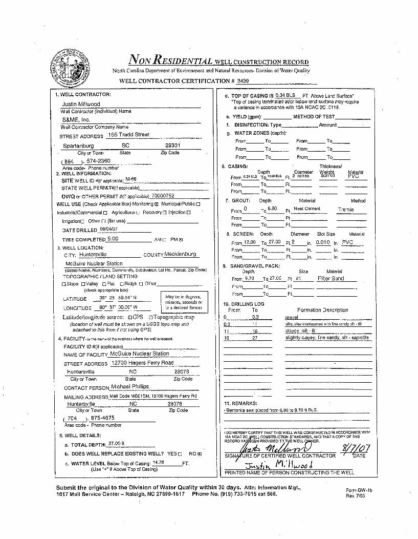
NON RESIDENTIAL WELL CONSTRUCTION RECORD
North Carolina Department of Environment and Natural Resources- Division of Water Quality
WELL CONTRACTOR CERTIFICATION # 3439
1. WELL CONTRACTOR:
Justin MillwoodWell Contractor (Individual) Name
S&ME, Inc.Well Contractor Company Name
STREET ADDRESS 155 Tradd Street
Spartanburg SC 29301City or Town State Zip Code
(864 )- 574-2360
Area code- Phone number2. WELL INFORMATION:
SITE WELL ID #(If applicable) M-66
STATE WELL PERMIT#(if applicable)_
DWQ or OTHER PERMIT #(if applicable) 70000752
WELL USE (Check Applicable Box) Monitoring 9] Municipal/Publicc]
Industrial/Commercial I] Agricultural o Recovery C Injection 0
Irrigation. Other I] (list use)
DATE DRILLED 06/04/07
TIME COMPLETED 5:00 AM E PM Iq
3. WELL LOCATION:CITY: Huntersvllle COUNTY Mecklenburg
McGuire Nuclear Station(Street Name, Numbers, Community, Subdivision. Lot No., Parcel, Zip Code)
TOPOGRAPHIC / LAND SETTING:
OSIope oValley CjFlaL ORidge E] Other(check eppropriate box)
LATITUDE 350 25' 59.54" N May be in degrecs,minutes, seconds or
LONGITUDE 80° 57' 00.09" W is a decimal format
Latitude/longitude source: oGPS oTopographic map(location of well must be shown on a USGS topo map and
attached to this form if not using GPS)
4. FACILITY. is the name of the business where the wall Is located.
FACILITY ID #(if applicable)
NAME OF FACILITY McGuire Nuclear Station
STREET ADDRESS 12700 Hagers Ferry Road
Huntersville NC 28078City or Town State Zip Code
CONTACT PERSON Michael Phillips
MAILING ADDRESS Mali Code MG01EM, 12700 Hagers Ferry RdHuntersville NC 28078
City or Town State Zip Code
704 ) 875-4675Area code - Phone number
5. WELL DETAILS:
a. TOTAL DEPTH: 27.00 ft
b. DOES WELL REPLACE EXISTING WELL? YES o NO 91
c. WATER LEVEL Below Top of Casing: 14.76 FT.(Use "+" if Above Top of Casing)
d. TOP OF CASING IS 0.34 BLS FT. Above Land Surface**Top of casing terminated at/or below land surface may require
a variance in accordance with 15A NCAC 2C .0118.
e. YIELD lgpm): _ METHOD OF TEST
f. DISINFECTION: Type_ Amount
g. WATER ZONES (depth):
From_ To _ From_ To
From_ To_ From_ To
From_ To_ From_ To
6. CASING: ThicknesslDepth Diameter Weigt al
From 0,34 BLS To 12,0BLs Ft. 2 Inches ch 4
From_ To - Ft. _ _
From - To_ Ft. _ _
7. GROUT: Depth Material Method
From 0 To 6.80 Fi. Neat Cement Tremie
From To Ft.
From_ To_ Ft.
8. SCREEN: Depth Diameter Slot Size Material
From 12.00 To 27.00 Ft.2
in. 0.010 In. PVC
From _ To Ft. in. _ in,
From_ To_ Ft. in. in.
9, SAND/GRAVEL PACK:Depth Size Material
From 9.70 To 27.00 Ft. 1l Filter Sand
From To_ Ft,_
From To_ Ft._
10, DRILLING LOGFrom To Formation Description
0 0.3 gravel
0.3 11 silty, clay interlayered with fine sandy slit - fill
11 16 clayey, silt - fill
16 27 slightly clayey, fine sandy, silt - saprolite
11. REMARKS:- Bentontle seal placed from 6.80 to 9.70 1t BLS.
(00 HEREBY CERTIFY THAT THIS WELL WAS CONSTRUCTED IN ACCORDANCE WITH15A NCAC 2C,)ýVELL CONSTRUCTION STANDARDS, AND THAT A COPY' OF THISRECORO HA IC PROVIDED To Cy WELL 91ER.
SIGNp/tURE OF CERTIFIED WELL CONTRACTOR DATE
PRINTED NAME OF PERSON CONSTRUCTING THE WELL
Submit the original to theDivision of Water Quality within 30 days. Attn: Information Mgt,,1617 Mail Service Center - Raleigh, NC 27699-1617 Phone No. (919) 733-7015 ext 568.
Form GW-lbRev. 7/05

noN RESIDENTIAL WELL CONSTRUCTION RECORD
North Carolina Department orEnvironment and Natural Resources- Division of Water Quality
WELL CONTRACTOR CERTIFICATION # 3439
1. WELL CONTRACTOR:
Justin MillwoodWell Contractor (Individual) Name
S&ME, Inc.Well Contractor Company Name
STREET ADDRESS 155 Tradd Street
Spartanburg SC 29301City or Town State Zip Code
_84_). 574-2360Area code- Phone number
2. WELL INFORMATION:SITE WELL ID #(if applicable) M-66R
STATE WELL PERMIT#(if applicable)
DWQ or OTHER PERMIT #(If applicable) 70000752
WELL USE (Check Applicable Box) Monitoring @, Municipal/Publio 0
Industrial/Commercial El Agricultural 0 Recovery 0 Injection [i
Irrigationo Other E (list use)
DATE DRILLED 06104/07
TIME COMPLETED 5:00 AM[I PM El
3, WELL LOCATION:CITY: Huntersville COUNTY Mecklenburg
McGulre Nuclear Station
d. TOP OF CASING IS 0.35 BLS FT. Above Land Surface**Top of casing terminated ai/or below land surface may requirea variance in accordance with 15A NCAC 2C .0118.
a. YIELD (gpm): _ METHOD OF TEST
f. DISINFECTION: Type_ _ Amount
g. WATER ZONES (depth):
From_ To_ From_ To____
From_ To_ From_ To
From_ To_ From_ To
6. CASING: Thickness/Depth Diameter Weight atVtrial
From _,35 BLS To 70s0aLs Ft. 2 inches
From_ To - Ft._From_ To_ Ft._
7. GROUT; Depth Material Method
From 0 To 65.00 Ft, Neat Cement Tremie
From To Ft.
From_ To__ Ft.
8. SCREEN: Depth Diameter Slot Size Material
From 70.80 To 75.80 Ft.2
in. 0.010 in. PVCFrom_ To_ Ft. in. _ in.
From_ To_ Ft. in, _ In.
9. SAND/GRAVEL PACK:Depth Size Material
From To_ Ft. -
From To_ Ft. -
From To_ Ft._
(Street Name, Numbers, Community, Subdivision, Lot No., Parcel, Zip Code)
TOPOGRAPHIC / LAND SETTING:
,SIope OValley OFlat ElRidge LI Other(check appropriate box)
LATITUDE 350 25' 59.49" N May be in degrees,minutes, seconds or
LONGITUDE 80* 57' 00.11 W" W in a decimal format
Latitude/longitude source: z GPS oTopographic map(location of well must be shown on a USGS topo map and
attached to this form if not using GPS)
4. FACILITY. is the name of the business where the wall Is losated.
FACILITY ID #(if applicable)_
NAME OF FACILITY McGuire Nuclear Station
STREET ADDRESS 12700 Hagers Ferry Road
Huntersville NC 28078
10. DRILLING LOGFrom To
0 0.30.3 11
11 1618 40
40 48.3
48.3 52
52 6363 6969 70.470.4 89.54
11. REMARKS:
Formation DescriptionwravelSilly, clay interlavered with fine sandy, sil.t -ill
clayey, silt - fill
slightly clayey, fine sandy, silt - saprolite
sllghtly clayey, sill - Seprollte
silt - saprolita
silty, medium to fine sand - saprolite
silty, medium to fine sand - weathered rock
coarse grained quartz diorite- partiaty weatnetere (k
coarse to line grained quartz diorite and meteCity or Town State Zip Coda
CONTACT PERSON Michael Phillips
MAILING ADDRESS Mall Code MG01 EM, 12700 Hagars Ferry RdHuntersville NC 28078
gabbro- sound rock
City or Town State
704 .) 875-4675
Area code- Phone number
Zip Code - K-packer placed st 70,09 to 70.11 feet BLS; bentonite seal placed at
65.00 to 70.09 It bis; sand pack placed below well from 75.80 to 77.00 it BLS.
- Bentonite placed below well 77.00 to 89.54 feat BLS.
5, WELL DETAILS:
a. TOTAL DEPTH: 75.80 It
b. DOES WELL REPLACE EXISTING WELL? YES 0 NO Et
c. WATER LEVEL Below Top of Casing: 48.61 FT.(Use "+" If Above Top of Casing)
I DO HEREBY CERTIFYTHAT THIS WELL WAS CONSTRUCTED IN ACCORDANCE WITH15A NcAC 2CvWEL CONSTRUG'nuON STANDARDS, AND THAT A COPY OF THISRECORO HRD EEN PROVIDED TO THD WELL gtN10ER.
SIGNytURE OF CERTIFIED WELL CONTRACTOR DATE
JY,.,-Is '/-•._ ilLA. oSPRINTED NAME OF PERSON CONSTRUCTING THE WELL
Submit the original to the Division of Water Quality within 30 days. Attn: Information Mgt.,1617 Mail Service Center- Raleigh, NC 27699.1617 Phone No. (919) 733-7015 ext 568.
Form GW-lbRev. 7105

VNON RESIDENTIAL WELL CONSTRUCTION RECORD
North Carolina Department of Environment and Natural Resources- Division orWater Quality
WELL CONTRACTOR CERTIFICATION # 3439
1. WELL CONTRACTOR:
Justin MillwoodWell Contractor (Individual) Name
S&ME, Inc.
Well Contractor Company Name
STREET ADDRESS 155 Tradd Street
Spartanburg SC 29301
City or Town State Zip Code
6(_64 ). 574-2360
Area code- Phone number2. WELL INFORMATION:
SITE WELL ID #(if applicable) M-70
STATE WELL PERMIT#(if applicable)
DWQ or OTHER PERMIT #(if applicable) 70000752
WELL USE (Check Applicable Box) Monitoring M3 Municipal/Public 0
Industrial/Commercial 0 Agricultural[] Recovery[ CInjection [
Irrigationrl Other [3 (list use)
DATE DRILLED 06/19/07
TIME COMPLETED 5:00 AMC] PMf E
3. WELL LOCATION:
CITY: Huntersville COUNTY Mecklenburg
McGuire Nuclear Station
(Street Name, Numbers, Community, Subdivision, Lot No., Parcel, Zip Code)TOPOGRAPHIC / LAND SETTING:
C Slope oValley CiFiat CRidge 0 Other(check appropriate box)
LATITUDE 350 26' 00.74" N May be in degrees,-minates, seconds or
LONGITUDE 80* 56' 57.89" W in a decimal tormat
Latitude/longitude source: oGPS oTopographic map(location of well must be shown on a USGS topo map andattached to this form if nol'using GPS)
4. FACILITY- is the name of the business where the wall is located.
FACILITY ID i(if applicable)_
NAME OF FACILITY McGuire Nuclear Station
STREET ADDRESS 12700 Hagers Ferry Road
Huntersville NC 28078
d, TOP OF CASING IS 0.26 BLS FT. Above Land Surfacae'Top of casing terminated atlor below land surface may require
a variance in accordance with 15A NCAC 2C .0118.
e. YIELD (gpm): METHOD OF TEST
f. DISINFECTION: Type _ Amount
g. WATER ZONES (depth):
From_ To_ From_ To____
From_ To_ From_ To_
From_ To_ From - To
6, CASING: Thickness/Depth Diameter Weight atet!rial
From 0.26OLS To 6.00BLs Ft. 2 inches ch4 V
From - To_ Ft._
From_ To _ Ft._
7. GROUT: Depth Material Method
From 0 To 1.50 Ft. Neat Cement Tremie
From_ To_ Ft.
From_ To_ Ft.
8. SCREEN: Depth Diameter Slot Size Material
From 6.00 To 21.00 Ft.2 in. 0.010 in. PVC
From To Ft. in, in.
From_ To_ Ft. in, in.
9, SAND/GRAVEL PACK:Depth Size Material
From 4.00 To 21.00 Ft. #1 Filter Sand
From To_ Ft.
From To Ft._
10. DRILLING LOGFrom To Formation Description
0 0.5 asphalt
0.5 7 slightly sandy, clayey, sill - lill
7 2 1 slightly clayey, medium to line sandy, sit - saprolile
11. REMARKS:
City or Town State Zip Coda
CONTACT PERSON Michael Phillips
MAILING ADDRESS Mall Code MG01EM, 12700 Hagers Ferry Rd
Huntersville NC 28078City or Town State
704 )- 875-4675Area code - Phone number
Zip Code
5. WELL DETAILS:
a. TOTAL DEPTH: 21.00 it
b. DOES WELL REPLACE EXISTING WELL? YES I NO Mj
o. WATER LEVEL Below Top of Casing: 11,19 FT.(Use "+" if Above Top of Casing)
I DO HEREBY CERTlFY THAT THIS WELL WAS CONSTRUCTED IN ACCOROANCE WITH15A NCAC 2C, WELL CONSTRUCTION STANDARDS, AND THAT A COPY OF THISRECOR -S BEEN PROVIDED TO THE W NER.
51G4R(URE OF CERTIFIED WELL CONTRACTOR DATE
PRINTED NAME OF PERSON CONSTRUCTING THE WELL
Submit the original to the Division of Water Quality within 30 days. Attn: Information Mgt.,1617 Mail Service Center- Raleigh, NC 27699-1617 Phone No. (919) 733-7015 ext 568.
Form GW-IbRev. 7/05

lYON RESIDENTIAL WELL CONSTRUCTION RECORD
North Carolina Department of Environment and Natural Resources- Division of Water Quality
WELL CONTRACTOR CERTIFICATION # 3439
1. WELL CONTRACTOR:
Justin MillwoodWell Contractor (Individual) Name
S&ME, Inc.Well Contractor Company Name
STREET ADDRESS 155 Tradd Street
Spartanburg SC 29301City or Town State Zip Code
(864 )- 574-2360Area code- Phone number
2. WELL INFORMATION:
SITE WELL ID #(If applicable) M-70R
STATE WELL PERMIT#(if applicable)
DWQ or OTHER PERMIT #(if applicable) 70000752
WELL USE (Check Applicable Box) Monitoring 00 Municipal/Public
Industrial/Commercial 0 Agricultural 0 Recovery 0 Injection 0
Irrigationo Other o (list use)
DATE DRILLED 08/18/07
TIME COMPLETED 5:00 AMD PM El
3. WELL LOCATION:
CITY: Huntersvllle COUNTY Mecklenburg
MCGuire Nuclear Station(Street Name, Numbers, Community, Subdivision, Lot No., Parcel, Zip Code)
TOPOGRAPHIC / LAND SETTING:
0Slope oValley 0Flat DRidge 0 Other(check appropriate box)
LATITUDE 35' 26' 00.73" N IvMay be in dugrees,mtinutes, seconds or
LONGITUDE 800 56' 57.83" W in a decimal format
Latitude/longitude source: ;0GPS oTopogttaphic map(location of well must be shown on a USGS topo map and
attached to this form if not using GPS)
4. FACILITY- is the name of the business where the wall is located,
FACILITY ID #(if applicable)
NAME OF FACILITY MoGuire Nuclear Station
STREET ADDRESS 12700 Hagers Ferry Road
Huntersvllle NC 28078
d. TOP OF CASING IS 0.22 BLS FT. Above Land Surface*'Top of casing terminated stlor below land surface may requirea variance in accordance with 15A NCAC 2C .0118.
e, YIELD (gpm): ,_,,_METHOD OF TEST
f, DISINFECTION: Type Amount
g. WATER ZONES (depth):
From_ To From_ To
From- To From_ To
From - To_ From_ To
6. CASING: Thickness/Depth Diameter Veight aterial
From e22 BLs To 55,4BLS Ft. 2 Inches ch 4
From- To_ Ft._From- To_ Ft.__
7. GROUT: Depth Material Method
From_ _ To 13.00 Ft. Neat Cement Tremie
From To Ft.
From_ To___ Ft.-----
8. SCREEN: Depth Diameter Slot Size Material
From 54.45 To 65.45 Fl2 in, 0.010 in. PVCFrom- To_ Fl. in. _ in.
From- To_ Ft. in. _ in.
9. SAND/GRAVEL PACK:Depth Size Material
From 53.50 To 65.45 Ft. ,.1 Filter Sand
From To _ Ft._
From To Ft.
10. DRILLING LOGFrom To Formation Description
0 0.5 asphalt
0.5 7 slightly sandy, clayey, silt -fill7 27 slightly clayey, medium to fine sandy, silt- saprolile
27 28.6 coarse sand - saprolite
28.6 32 slightly clayey, line sandy, sill - satfolile
32 48 fine sandy, silt - saprolite
48 48.7 fine sandy, silt - weathered rock
48.7 65.45 silly, coarse to fine sand - weathered rock
11. REMARKS:- Bentonite seal placed from 13 to 53.50 It BLS.
City or Town State Zip Code
CONTACT PERSON Michael Phillips
MAILING ADDRESS Mall Code MGOl EM, 12700 Hagers Ferty Rd
Huntersville NC 28078City or Town State Zip Code
704 ) 875-4675Area code - Phone number
5. WELL DETAILS:
a. TOTAL DEPTH: 65.45 It
b. DOES WELL REPLACE EXISTING WELL? YES 0 NO [9
c. WATER LEVEL Below Top of Casing: 12.41 FT.(Use "+" if Above Top of Casing)
I 00 hEREBY CERTIFY THAT tHiS WELL WAS CONSTRUCTED IN ACCORDANCE WITH15A NCAC2 WELL CONSTRUCTION STANDARDS. AND THAT A COPY OF THISRECORD EENPR.VIDE.TO EWELNER.
SIGOATURE OF CERTIFIED WELL CONTRACTOR DATE
PRINTED NAME OF PERSON CONSTRUCTING THE WELL
Submit the original to the Division of Water Quality within 30 days. Attn: Information Mgt.,1617 Mail Service Center- Raleigh, NC 27699-1617 Phone No. (919) 733-7015 ext 568.
Form GW-1 bRev. 7/05
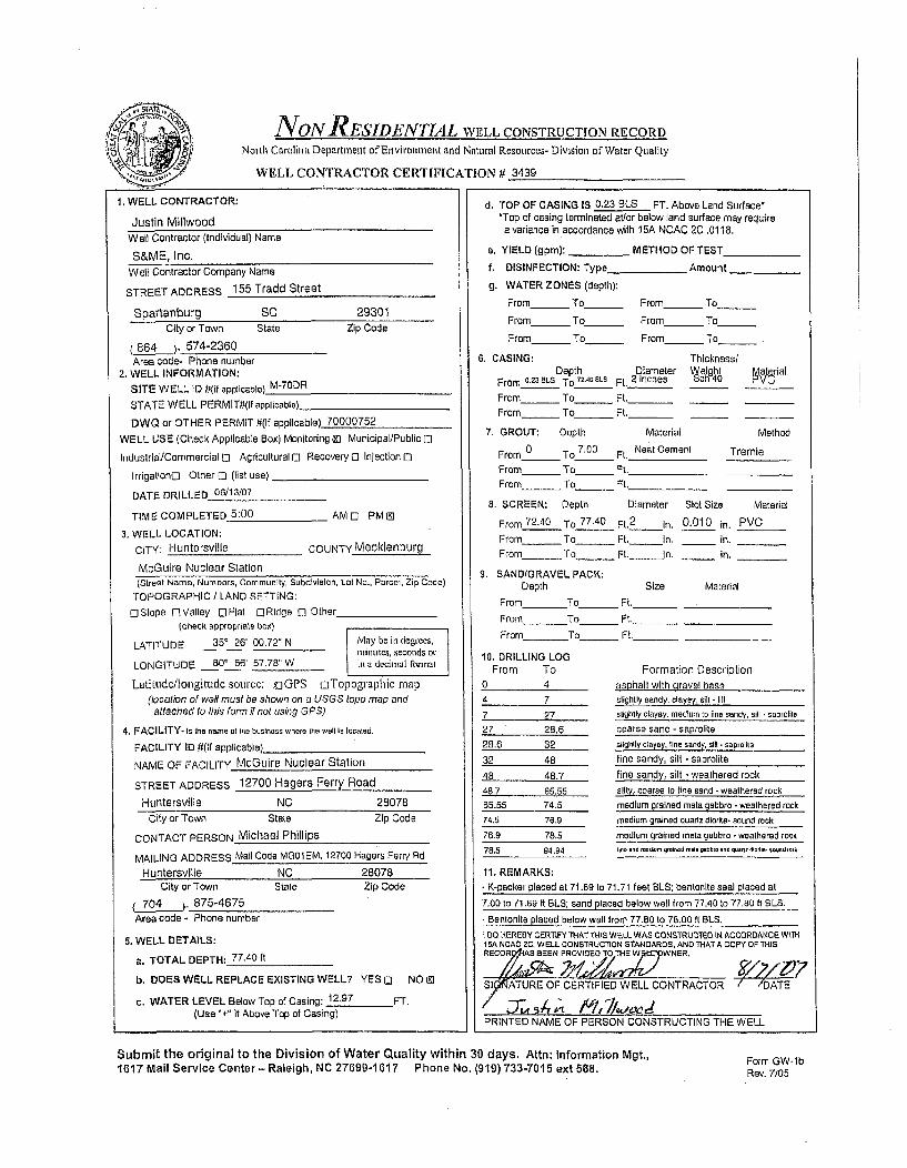
NON RESIDENTIAL WELL CONSTRUCTION RECORD
Norlh Carolina Department of Environment and Natural Resources- Division of Water Quality
WELL CONTRACTOR CERTIFICATION # 3439
1, WELL CONTRACTOR:
Justin MillwoodWell Contractor (Individual) Name
S&ME, Inc.Well Contractor Company Name
STREET ADDRESS 155 Tradd Street
Spartanburg SC 29301
City or Town State Zip Code
(864 )- 574-2360Area code- Phone number
2. WELL INFORMATION:
SITE WELL ID #(if applicable)_ M-70DR
STATE WELL PERMIT#lIf applicable)
DWO or OTHER PERMIT #(if applicable) 70000752
WELL USE (Check Applicable Box) Monitoring M Municipal/Public L]
Industrial/Commercial 0] Agricultural 0 Recovery 1 Injection 1
Irrigationo Other 0 (list use)
DATE DRILLED 06113/07
TIME COMPLETED 5:00 AMO PMI E
3. WELL LOCATION:
CITY: Huntersville COUNTY Mecklenburg
McGuire Nuclear Station(Street Name, Numbers, Community, Subdivision, Lot No., Parcel, Zip Code)
TOPOGRAPHIC / LAND SETTING:
[]Slope OValley OFlat r-Ridge [ Other___(check appropriate box)
LATITUDE 35' 26' 00.72" N May be it deg'ees,minutes, seconds or-
LONGITUDE 80' 56' 57.78" W il a decimal format
Latitude/longitude source: UGPS oTopographic map
(location of weai must be shown on a USGS topo map andattached to this form if not using GPS)
4, FACILITY- is the name at the business where the well Is located.
FACILITY ID #(if applicable)_
NAME OF FACILITY McGuire Nuclear Station
STREET ADDRESS 12700 Hagers Ferry Road
Huntersville NC 28078
d. TOP OF CASING IS 0,23 BLS FT. Above Land Surface*'Top of casing terminated ateor below land surface may require
a variance in accordance with 15A NCAC 2C .0118.
a. YIELD (gpm): METHOD OF TEST
f. DISINFECTION: Type Amount
g. WATER ZONES (depth):
From_ To_ From - To
From_ To_ From_ To
From To_ _ From_ To
6. CASING: ThicknessiDepth Diameter eihght Matrial
From .2m eLS To I.IAD 8 Ft. 2 Inches ch 40
From_ To_ Ft._ _
From_ To_ Ft._ _
7. GROUT: Depth Material Method
From 0 To 7.00 Ft. Neat Cement Tremle
From To Ft.
From_ To _ Ft.
8. SCREEN: Depth Diameter Slot Size Material
From 72.40 To 77.40 Ft,2
In. 0.010 in. PVC
From To Ft. In, in.
From To Ft. In. in.
S. SANDIGRAVEL PACK:Depth Size Material
From To Ft._
From To_ Ft._
From To _Ft.
10, DRILLING LOGFrom To
0 4
4 7
7 2727 28.6
2B.6 32
32 48
48 48.7
48.7 65.5565.55 74.5
74.5 76.9
76.9 78.5
78.5 94.94
11. REMARKS:
Formation Descriptionasphalt with gravel baseslightly sandy, clayey, silt - till
slightly clayey, nedlum to fine sandy, sill • saprolite
coarse sand - seprolite
slightly clayey, line sandy, sill t saprolite
fine sandy, sill - saprolite
fine sandy, silt - weathered rook
silty, coarse to fine sand -weathered rock
medium grained meta gabbro -weathered rock
City or Town State
CONTACT PERSON Michael Phillips
Zip Code medium grained quarlz diodte- sound rock
medium grained meta gabbro -weathered rockhine and modcurn grievod -ea gabbo -nd quror Mode. sound lOiu,
MAILING ADDRESS Mail Code MOSL EM, 12700 Hagers Ferry Rd
Huntersvllle NC 28078City or Town State
L70._4 - 875-4675Area code - Phone number
Zip Code - K-packer placed at 71.69 to 71.71 feet BLS; bentonite seal placed at
7.00 to 71.69 ft BLS: sand placed below well from 77.40 to 77.80 ft BLS.
- Bentonite placed below well from 77.80 to 78,00 ft BLS.
5. WELL DETAILS:
a. TOTAL DEPTH: 77.40 It
b. DOES WELL REPLACE EXISTING WELL? YES 0 NO E]
c. WATER LEVEL Below Top of Casing: 12.97 FT.(Use "+" if Above Top of Casing)
I DO HEREBY CERtFY THAT THIS WELL WAS CONSTRUOTEO IN ACCORDANCE WITHt5A NCAO 20, WELL CONSTRUCTION STANDARDS, AND THAT A COPY OF THISRECOR IIAS BEEN PROVIDEO TO THE W~rcpWNER,
SIPATURE OF CERTIFIED WELL CONTRACTOR DATE
/ J74:1 ~i7L..'-PRINTED NAME OF PERSON CONSTRUCTING THE WELL
Submit the original to the Division of Water Quality within 30 days. Attn: Information Mgt.,1617 Mail Service Center- Raleigh, NC 27699-1617 Phone No. (919) 733-7015 ext 568.
Form GW-lbRev. 7/05

JVON RESIDENTIAL WELL CONSTRUCTION RECORD
North Carolina Department of Environment and Natural Resources- Division or Water Quality
WELL CONTRACTOR CERTIFICATION It 2717
1. WELL CONTRACTOR:
Jay LittleWell Contractor (individual) Name
S&ME, Inc.Well Contractor Company Name
STREET ADDRESS 9751 Southern Pine Boulevard
Charlotte NC 28273City or Town State Zip Code
(704 )- 523-4726Area code- Phone number
2. WELL INFORMATION:SITE WELL ID #(if applicable) M-94
STATE WELL PERMIT#(If applicable)
DWQ or OTHER PERMIT #(if applicable) 70000752WELL USE (Check Applicable Box) Monitoring KJ Municipal/Public C
Industrial/Commercial 0 Agriculturalo Recovery 0 Injection c
Irrigationol Other o (list use).
DATE DRILLED 06/28/07
TIME COMPLETED 5:00 AMO PME
3. WELL LOCATION:CITY: Huntersville COUNTY Mecklenburg
McGuire Nuclear Station(Street Name, Numbers, Community, Subdivision, Lot No., Parcel, Zip Code)
TOPOGRAPHIC / LAND SETTING:L Slope oValley [OFlat iRidge C Other___
(check appropriate box)
LATITUDE 35' 25' 53.57' N Mlay be in degrees,minutes, seconds or
LONGITUDE 80' 57' 06.09" W in a decimal tlrmat
Latinide/longitudesource: xCGPS cTopographic map(location of well must be shown on a USGS topo manp and
attached to this form if not using GPS)
4. FACILITY. Is the name of the business where the well Is located.
FACILITY ID #(if applicable)
NAME OF FACILITY McGuire Nuclear Station
STREET ADDRESS 12700 Hagers Ferry Road
Huntersvllle NC 28078
d. TOP OF CASING IS 2.96 FT. Above Land Surface*'Top of casing terminated al/or below land surface may require
a variance in accordance with 15A NCAC 2C .0118.
e. YIELD (gpm): _ METHOD OF TEST
f, DISINFECTION: Type Amount
g. WATER ZONES (depth):
From To From To
From - To_ _ From To_
From To From To
6. CASING: Thickness/Depth Diameter Weight Material
From 2.9BALs To29. 1 LG Ft. 21nches ch 40 PVC
From_ To_ Ft.__
From To Ft.
7. GROUT: Depth Material Method
From 0 To 24.00 Ft. Neat Cement TremieFrom To Ft.
From _ To_ Ft.
8. SCREEN: Depth Diameter Slot Size Material
From 29.10 To 44,10 Ft 2 In. 0.010 in. PVCFrom To Ft. in. In.
From_ To_ _ Ft. in. in.
9. SAND/GRAVEL PACK:Depth Size Material
From 27.00 To 44.10 Ft. #1 Filter SandFrom To_ Ft._
From To_ _ Ft._
10, DRILLING LOGFrom To
0 9
9 14
14 1919 19.2
19.2 23
23 29
29 35.5
35.5 44,1
Formation Descriptiontines snndr ,4iil .clihr, li rnfine sandw silt - alluviumclayey, silt - alluvium
silty, clay - alluviumfine sandy, silt - alluviummedium to line sandy, clay - alluvium
slightly clayey, fine sandy, slit - saprolite
coarse to fine sandy, silt - saprolite
fine sandy, sill - saprollte
City or Town State Zip Code
CONTACT PERSON Michael Phillips
MAILING ADDRESS Mall Code MG01 EM, 12700 Hagers Ferry Rd
Huntersville NC 28078 11. REMARKS:City or Town State
704 )- 875-4675Area code - Phone number
Zip Code
5. WELL DETAILS:
a. TOTAL DEPTH: 44.10 It
b. DOES WELL REPLACE EXISTING WELL? YES 0 NO 1]
c. WATER LEVEL Below Top of Casing: 35.43 FT.(Use "+" if Above Top of Casing)
1 O0 HEREBY CERTIFYTHATTHIS WELL WAS CONSTRUCTEO IN ACCORDANCE WITH15A NOAC 2C, WELL CONSTRUCTION STANDARDS. AND THATA COPY OF THISRECORD HAS.BEEN PROVIDED TO THE WELL OWNER.
S,ý ATEOF CERTIFIED WELL CONTRACTOR DATE
PRINTED NWAME OF PERSON CONSTRUCTING THE WELL
Submit the original to the Division of Water Quality within 30 days. Attn: Information Mgt.,1617 Mail Service Center - Raleigh, NC 27699-1617 Phone No. (919) 733-7015 ext 568. Form GW-lb
Rev. 7/05

NYON RESIDENTIAL WELL CONSTRUCTION RECORDNorth Carolina Department of Environment and Natural Resources- Division orWater Quality
WELL CONTRACTO1R CERTIFICATION # 3439
1, WELL CONTRACTOR:
Justin Millwood
Well Contractor (Individual) Name
S&ME, Inc.Well Contractor Company Name
STREET ADDRESS 155 Tradd Street
Spartanburg SC 29301
City or Town State Zip Code
(864 _ ) 574-2360Area code- Phone number
2. WELL INFORMATION:SITE WELL ID #(If applicable) M-lO4DR
STATE WELL PERMIT#(it applicable).
DWQ or OTHER PERMIT #(If applicable) 70000752
WELL USE (Check Applicable Box) Monitoring Ml Municipal/Public 0]
Industrial/Commercial 0 Agricultural 0 Recoveryo Injection [
IrrigationD Other 0 (list use)
DATE DRILLED 07/10/07
TIME COMPLETED 5:00 AM 0 PM Z]
3. WELL LOCATION:CITY: Huntersville COUNTY Mecklenburg
McGuire Nuclear Station(Street Name, Numbers, Community, Subdivision, Lot No., Parcel, Zip Code)
TOPOGRAPHIC / LAND SETTING:OSIope OValley COFlal oRidge 0 Other
(check appropriate box)
LATITUDE 35 25' 51.88" N May be ii degrees,minutes, seconds or
LONGITUDE 80 57' 16.24" W in a decimal ionrat
Latitutde/longitttde source: 0jOPS DTopographic map(location of well must be shown on a USGS topo map and
attached to this form if not using GPS)
4. FACILITY- is the name of the business where the well is located.
FACILITY ID #(if applicable)
NAME OF FACILITY McGuire Nuclear Station
STREET ADDRESS 12700 Hagers Ferry Road
Huntersville NC 28078City or Town State Zip Code
CONTACT PERSON Michael Phillips
MAILING ADDRESS Mail Code MG01 EM, 12700 Hagars Ferry RdHuntersville NC 28078
City or Town State Zip Code
704 )- 875-4675Area code - Phone number.
5. WELL DETAILS:
a. TOTAL DEPTH: 76.00 ft
b. DOES WELL REPLACE EXISTING WELL? YES 0 NO 91
c. WATER LEVEL Below Top of Casing: 42,51 FT.(Use "+" If Above Top of Casing)
d. TOP OF CASING IS 3.02 FT. Above Land Surface**Top of casing terminated al/or below land surface may require
a variance in accordance with 15A NCAC 2C .0118,
a. YIELD (gpm): _ METHOD OF TEST
f. DISINFECTION: Type_ _ Amount
g, WATER ZONES (depth):
From_ To_ From_ To___
From- To_ From_ To
From To_ _ From_ To
6. CASING: Thickness/Depth Diameter T~ONchg Mlarial
From 3.02ALS To71.008Ls Ft. 2 inches VC
From - To_ Ft,.From _ To_ Ft. -
7. GROUT: Depth Material Method
From_ To_ Ft.
From To Ft.
From_ To_ Ft.
B. SCREEN: Depth Diameter Slot Size Material
From 71.00 To 76.00 Ft.2
in. 0,010 in. PVCFrom To Ft. 'in. In,
From _ To _ Ft. in. in.
9. SANDIGRAVEL PACK:Depth Size Material
From To_ Ft._
From To_ Ft.
From To_ Ft.
10. DRILLING LOGFrom To Formation Description
0 8 medium to fine sandy silty clay
8 36.70 silty fine to med/coarse sand
36.70 refusal to roller cone drill bit36.70 80.28 weathered and sound rook -coarse gralned granite
11. REMARKS:
- K-packer placed at 70.29 to 70.31 ft BLS: bentonite seal placed at
0 0o 70,29 ft 8LS; sand/tIlter pack placed below well from 75.00 to 77.50 ft BLS.
- Bentonite placed below well from 77.50 to 80.28 feet BLS.
t0o HEREBY CERTIFY THAT THIS WELL WAS CONSTRUCTED IN ACCOROANCE WITH15A NCAC C, WELL CONSTRUCTION STAND a4., AND THATA COPY OF THISRECORfAS BEEN PROVIDED TO THC L 0 ER.
SI•1 IATURE OF CERTIFIED WELL CONTRACTOR f ATE
P ,TD. -AM. OFPRSNCO U TPRINTED NAME OF PERSON CONSTRUCTING THE WELL
Submit the original to the Division of Water Quality within 30 days. Attn: Information Mgt.,1617 Mail Service Center- Raleigh, NC 27699-1617 Phone No. (919) 733-7015 ext 568. Form GW-lb
Rev. 7/05

SS&ME
February 4, 2008
Mecklenburg County Health DepartmentLand Use & Environmental Service AgencyGroundwater & Wastewater Services700 North Tryon Street, Suite 211Charlotte, North Carolina 28202
Reference: Non-Residential Well Construction Records - Submittal #5Mcguire Nuclear Station12700 Hagers Ferry RoadHuntersville, North CarolinaWell Application Permit No. 70000752S&ME Project No. 1264-06-724
Ladies and Gentlemen:
On behalf of Duke Energy, S&ME, Inc. (S&ME) is submitting the enclosed Monitor WellRegistration form and completed/signed Non-Residential Well Construction Records for thefollowing eleven (11) groundwater monitoring wells installed at the McGuire Nuclear Station(MNS) site:
* M-20 * M-22 . M-31 * M-91• M-20R 0 M-22R • M-35 • M-91R.• M-21 0 M-23 * M-60
Duke Energy has voluntarily installed groundwater monitoring wells at MNS as part of a site-wide hydrogeologic evaluation. As of this writing, the above eleven (11) wells represent the lastplanned wells for this project at MNS. Therefore, we anticipate this submittal (Submittal #5) tobe the last for this project.
On behalf of Duke Energy, S&ME thanks you for your receipt of these records. Should youhave any questions or need additional information, please contact us.
Sincerely,S&ME, Inc.
Mary Beth Cline, E.I.T.
Staff Professional
enclosures
cc: Messrs. Greg Robison, Ed Sullivan, Tim Hunsucker; Duke Energy
SA.'ENVIRONM2006\1264 Projects\6406724 McGuire Nuclear Groundwater Study\NCDENR Well Recordsineck co well records su nittal 5.doc
S&ME, INC. / 155 Tradd Street / Spartanburg, SC 29301 / p 864.574.2360 f 864.576.87301 Marcus Drive, Suite 301 / Greenville, SC 29615 /p 864-232-8987 / www.s-neinc.com

Mecklenburg CountyLand Use & Environmental Service AgencyGroundwater & Wastewater Services700 N. Tryon St., Suite 211Charlotte, NC 28202Phone: (704) 336-5103Fax: (704) 336-6894
staeff Use OCIlyDate eev:
Monitor Well Registration
Is this Registration for a well or wells that existed prior to January 01, 2005?
Enter your Subsurface Investigation Permit #: 70000752 Date Well Installation Began: 11-27-07
Date Well Installation Complete: 01-08-08
Site/Contact Information Bill to Owner/Agent Name: Duke Energy / Michael Phillips
Name of Site: McGuire Nuclear Station Owner/Agent Address: Mail Code MG01EM 12700 Hagers Ferry Rd.
Site Address: 1 2 7 0 0 Hagers Ferry Road Owner/Agent Phone #: 704-875-4675
Site Tax Parcel ID: 00119103 Driller Certification #: 3439 & 2717
Type of Registration
This registration is for (check all that apply):
[] Unregistered Permanent Monitor Wells El Yearly Update of Permanent Monitor Wells
El Temporary Monitor Wells
The following information must be completed for each tax parcel on which monitor wells have been installed:
On-Site Monitor Wells Tax Parcel # Tax Parcel # Tax Parcel #
Type of Well # Present Type of Well # Present Type of Well # Present Type of Well # Present
Temporary' Temporary* Temporary* Temporary*
Permanent 11 Permanent Permanent Permanent
Sparge Sparge Sparge Sparge
Vapor Extraction Vapor Extraction Vapor Extraction Vapor Extraction
Recovery Recovery Recovery Recovery
Injection Injection Injection Injection
Vapor Monitoring Vapor Monitoring Vapor Monitoring Vapor Monitoring
Piezometer Piezometer Piezometer Piezometer
Groundwater Standard Groundwater Standard Groundwater Standard Groundwater Standard
Exceeded? Exceeded? Exceeded? Exceeded?
Tax Parcel # Tax Parcel # Tax Parcel # Tax Parcel #
Type of Well # Present Type of Well # Present Type of Well # Present Type of Well # Present
Temporary* Temporary* Temporary* Temporary*
Permanent Permanent Permanent Permanent
Sparge Sparge Sparge Sparge
Vapor Extraction Vapor Extraction Vapor Extraction Vapor Extraction
Recovery Recovery Recovery Recovery
Injection Injection Injection Injection
Vapor Monitoring Vapor Monitoring Vapor Monitoring Vapor Monitoring
Piezometer Piezometer Piezometer Piezometer
Groundwater Standard Groundwater Standard Groundwater Standard Groundwater Standard
Exceeded? Exceeded? Exceeded? Exceeded?
*Selection of Temporary Well requires monitor well abandonment forms also be filed. Failure to file abandonment forms will result in the well beingconsidered permanent and cause the well owner to be billed the appropriate fee.
MNS MW Reg Form Feb 08 JLS t2/13104 finol

NONRESIDENTIAL WELL CONSTRUCTION RECORDNorth Carolina Department of Environment and Natural Resources- Division of Water Quality
WELL CONTRACTOR CERTIFICATION # 2717
1. WELL CONTRACTOR:
Jay LittleWell Contractor (Individual) Name
S&ME, Inc.Well Contractor Company Name
STREET ADDRESS 9751 Southern Pine Boulevard
Charlotte NC 28273City or Town State Zip Code
(704 - 523-4726Area code- Phone number
2. WELL INFORMATION:SITE WELL ID #(if applicable) M-20
STATE WELL PERMIT#(if applicable)
DWQ or OTHER PERMIT #(if applicable) 70000752
WELL USE (Check Applicable Box) Monitoring a] MunicipalVPublic o
lndustriallCommercial [] Agricultural o Recovery 0 Injection E]
Irdgation[o Other 0l (list use)
DATE DRILLED 12/11/07
TIME COMPLETED 5:00 AM 0 PM 31
3. WELL LOCATION:CITY: Huntersville COUNTY Mecklenburg
McGuire Nuclear Station(Street Name, Numbers, Community, Subdivision, Lot No., Parcel, Zip Code)
TOPOGRAPHIC / LAND SETTING:0 Slope OValley 0 Flat J3Ridge [ Other
(check appropriate box)
LATITUDE 35 25' 36.52" N May be in degrees,mninutes, seconds or
LONGITUDE 80 57' 10.43"W in a decimal format
Latitude/longitude source: X]GPS [Topographic map(location of well must be shown on a USGS topo map andattached to this form if not using GPS)
4. FACILITY- is the name of the business where the well is located.
FACILITY ID #(if applicable)_
NAME OF FACILITY McGuire Nuclear Station
STREET ADDRESS 12700 Hagers Ferry Road
Huntersville NC 28078
d. TOP OF CASING IS 2.96 FT. Above Land Surface"*Top of casing terminated at/or below land surface may requireavariance in accordance with 15A NCAC 2C .0118.
e. YIELD (gpm): METHOD OF TEST
f. DISINFECTION: Type Amount____
g. WATER ZONES (depth):
From To From To
From_ To_ _ From - To
From_ To_ From_ To
6. CASING: Thickness/Depth Diameter /eeigh NVrial
From 2.B& AL5 To 33.00 RLS Ft. 2 inches ch4
From_ To - Ft._From_ To - Ft._
7. GROUT: Depth Material Method
From 0 To 29.00 Ft. Portland Tremie
From To Ft.From___ To Ft._
8. SCREEN: Depth Diameter Slot Size Material
From 33.00 To 48.00 Ft.2 in. 0.010 in. PVCFrom _ To_ Ft._ in. _ in.From_ To Ft. in, _ in.
9. SANDIGRAVEL PACK:Depth Size Material
From 31.00 To 4 8.00 Ft. #1 Filter Sand
From To_ Ft._
From To Ft._
10. DRILLING LOGFrom To Formation Description
0 0.3 grass/rootmat/toosoil
0.3 1310 fine sandy silty clay130 170 slightly clayey fine sandy silt17.0 23.0 silty fine sand23.0 37,0 slightly micaceous fine sandy silt
37.0 49-0 micaceous silty fine sand4.q 0 p 2- micaceous silty fine sand-weathered rock
52.3 roller cone bit refusal
11. REMARKS:
City or Town State Zip Code
CONTACT PERSON Michael Phillips
MAILING ADDRESS Mail Code MG01 EM, 12700 Hagers Ferry Rd
Huntersville NC 28078City or Town State
I704 '_ 875-4675Area code - Phone number
Zip Code
I 00 HEREBY CERTIFY THAT THIS WELL WAS CONSTRUCTED IN ACCORDANCE WITH15A NCAC 2C, WELL CONSTRUCTION STANDARDS, AND THAT A COPY OF THISRECORD HAS BEEN PROVIDED TO THE WELL OWNER.
Iý - V
5. WELL DETAILS:
a. TOTAL DEPTH: 48.00 ft
b. DOES WELL REPLACE EXISTING WELL? YES El NO Nl
c. WATER LEVEL Below Top of Casing: 41.17 FT.(Use "+" if Above Top of Casing)
,0I1"NOORE OF CERTFIFED WELL CONTRACTOR DATE
PRINTED NA"ME OF PERSON CONSTRUCTING THE WELL
Submit the original to the Division of Water Quality within 30 days. Attn: Information Mgt.,1617 Mail Service Center- Raleigh, NC 27699-1617 Phone No. (919) 733-7015 ext 568.
Form GW-lbRev. 7/05

NONRESIDENTIAL WELL CONSTRUCTION RECORD
North Carolina Department of Environment and Natural Resources- Division of Water Quality
WELL CONTRACTOR CERTIFICATION # 2717
1. WELL CONTRACTOR:
Jay LittleWell Contractor (Individual) Name
S&ME, Inc.Well Contractor Company Name
STREET ADDRESS 9751 Southern Pine Boulevard
Charlotte NC 28273City or Town State Zip Code
(704 - 623-4726Area code- Phone number
2. WELL INFORMATION:SITE WELL ID #(if applicable) M-20R
STATE WELL PERMIT#(if applicable)
DWQ or OTHER PERMIT #(if applicable) 70000752
WELL USE (Check Applicable Box) Monitoring 91 Municipal/Public L]
Industrial/Commercial [I Agricultural 0 Recovery 0 Injection [3
Irrigation[] Other 0 (list use)
DATE DRILLED 12/10/07
TIME COMPLETED 5:00 AM D PM ZI
3. WELL LOCATION:
CITY: Huntersville COUNTY Mecklenburg
McGuire Nuclear Station(Street Name, Numbers, Community, Subdivision, Lot No., Parcel, Zip Code)
TOPOGRAPHIC I LAND SETTING:o Slope oValley 0OFlat E3Ridge 0 Other
(check appropriate box)
LATITUDE 35 25' 36.50" N May be in degrees,minutes, seconds or
LONGITUDE 80 57' 10.36"W in a decimal format
Latitude/longitude source: fJGPS EiTopographic map(location of well must be shown on a USGS topo map andattached to this form if not using GPS)
4. FACILITY- Is the name of the business where lhe well is located,
FACILITY ID #(if applicable)
NAME OF FACILITY McGuire Nuclear Station
STREET ADDRESS 12700 Hagers Ferry RoadHuntersville NC 28078
City or Town State Zip Code
CONTACT PERSON Michael Phillips
MAILING ADDRESS Mail Code MG01EM, 12700 Hagers Ferry Rd
Huntersville NC 28078City or Town State Zip Code
704 ý_ 875-4675Area code - Phone number
5. WELL DETAILS:
a. TOTAL DEPTH: 67.49 ft
b. DOES WELL REPLACE EXISTING WELL? YES 0 NO El
c. WATER LEVEL Below Top of Casing: 38.97 FT.(Use "+" if Above Top of Casing)
d. TOP OF CASING IS 2.94. FT. Above Land Surface**Top of casing terminated at/or below land surface may require
a variance in accordance with 15A NCAC 2C .0118.
a. YIELD (gpm): _ METHOD OF TEST
f. DISINFECTION: Type Amount
g. WATER ZONES (depth):
From To From To
From_ To _ From_ To
From_ To_ From_ To
6. CASING: Thickness/Depth Diameter sean
From 2.94 ALS To 62.49 RLs Ft. 2 inches
From_ To_ Ft._
From_ To_ Ft._
7. GROUT: Depth Material Method
From 0 To 59.92 Ft. Portland Tremie
From To Ft.
From_ To Ft.
8. SCREEN: Depth Diameter Slot Size Material
From 62.49 To 67.49 Ft.2 in. 0.010 in. PVCFrom _ To _ Ft. in. in.
From _ To _ Ft. in. in.
9. SAND/GRAVEL PACK:Depth Size Material
From To_ Ft._
From To_ Ft.
From To _ Ft._
10. DRILLING LOGFrom To
0 0.30.3 13.0,1V0 17017.0 23.023.0 37.037.0 49.04•0 .521
52.3 75.0
Formation Descriptiongrass/rootmat/togsoitfine sandy silty claysliahtlv clavev fine sandy silt
silty fine sandslightly micaceous fine sandy silt
micaceous silty fine sandmicaceous silty fine sand-weathered rock
medium to coarse orained quartz diorite
11. REMARKS:- bentonite placed below well from 70.0 to 75 ft BLS; sand placed at 67.49 to 70 It BLS
- K-packer placed at 61.92 to 62.09 ft BLS; bentonite seal placed at
59.92 to 61.92 ft BLS; no sand/gravel pack below K-packerI DO HEREBY CERTIFY THAT THIS WELL WAS CONSTRUCTED IN ACCORDANCE WITH15A NCAC 2C, WELL CONSTRUCTION STANDARDS, AND THAT A COPY OF THISRECORD HABEEN PROVIDED TO THE WELL OWNER,
It ATrOF CERTIFIED WELL CONTRACTOR DATE
PRINTEIf NAME OF PERSON CONSTRUCTING THE WELL
Submit the original to the Division of Water Quality within 30 days. Attn: Information Mgt.,1617 Mail Service Center- Raleigh, NC 27699-1617 Phone No. (919) 733-7015 ext 568.
Form GW-1 bRev. 7/05

NON RESIDENTIAL WELL CONSTRUCTION RECORDNorth Carolina Department of Environment and Natural Resources- Division of Water Quality
WELL CONTRACTOR CERTIFICATION # 2717
1. WELL CONTRACTOR:
Jay LittleWell Contractor (Individual) Name
S&ME, Inc.Well Contractor Company Name
STREET ADDRESS 9751 Southern Pine Boulevard
Charlotte NC 28273City or Town State Zip Code
(704 . 523-4726Area code- Phone number
2. WELL INFORMATION:SITE WELL ID #(if applicable) M-21
STATE WELL PERMIT#(if applicable)_
DWQ or OTHER PERMIT #(if applicable) 70000752
WELL USE (Check Applicable Box) Monitoring 9) Municipal/Public D
Industrial/Commercial 0 Agricultural 0 Recovery 0 Injection D
IrrigationD Other 0 (list use)
DATE DRILLED 12/12/07
TIME COMPLETED 5:00 AM D PM []
3. WELL LOCATION:
CITY: Huntersville COUNTY Mecklenburg
McGuire Nuclear Station
d. TOP OF CASING IS 2.94 FT. Above Land Surface**Top of casing terminated atfor below land surface may require
a variance in accordance with 15A NCAC 2C .0118.
e. YIELD (gpm): METHOD OF TEST
f. DISINFECTION: Type Amount
g. WATER ZONES (depth):
From_ To_ From _ To
From To From To
From_ _ To _ From_ To
6. CASING: Thickness/Depth Diameter a•cig•t nat(•dalFrom 2.98 ALS To 30.00oeLs Ft. 2 inches IS
From_ To_ Ft._
From_ To_ Ft.
7. GROUT: Depth Material Method
From_ 0 To_24.00 Ft. Portland Tremie
From To Ft.
From _ To___ Ft.
8. SCREEN: Depth Diameter Slot Size Material
From 30.00 To 50.00 Ft. 2 in. 0.010 in. PVCFrom _ To___ Ft. in. _ in.
From__ To__ Ft. in. - in.
9. SANDIGRAVEL PACK:Depth Size Material
From 27.00 To 50.20 Ft. #1 Filter SandFrom To_ Ft.
From To Ft._
10. DRILLING LOGFrom To Formation Description
0 40.38 clavey silt40.38 50.50 micaceous silty sand
11. REMARKS:
(Street Name, Numbers, Community, Subdivision, Lot No., Parcel, Zip Code)
TOPOGRAPHIC I LAND SETTING:
0Slope DValley 0Flat flRidge 0 Other_(check appropriate box)
LATITUDE 35 25' 35.69" N May be in degrees,minutes, seconds or
LONGITUDE 80 56' 48.59"W in a decimal format
Latitude/longitude source: g]GPS oTopographic map(location of well must be shown on a USGS topo map andattached to this form fneot using GPS)
4. FACILITY. is the name of the business where the well is located.
FACILITY ID #(if applicable)
NAME OF FACILITY McGuire Nuclear Station
STREET ADDRESS 12700 Hagers Ferry Road
Huntersville NC 28078
City or Town State Zip Code
CONTACT PERSON Michael Phillips
MAILING ADDRESS Mail Code MG01 EM, 12700 Hagers Ferry Rd
Huntersville NC 28078City or Town State
704 ) 875-4675Area code - Phone number
Zip Code
5. WELL DETAILS:
a. TOTAL DEPTH: 50.00 ft
b. DOES WELL REPLACE EXISTING WELL? YES 0 NO 91
c. WATER LEVEL Below Top of Casing: 38.77 FT.(Use "+" if Above Top of Casing)
I 00 HEREBY CERTIFY THAT THIS WELL WAS CONSTRUCTED IN ACCORDANCE WITHISA NCAC 2C, WELL CONSTRUCTION STANDARDS, AND "HAT A COPY OF THISRECORDJ5S BEEN PROVIDED TO THE WELL OWNER.
7-7<aL, ~ - 2 -661 'C,,SaNAT)AE OF CERTIFIED WELL CONTRACTOR
7, 22tt4-DATE
PRINTEDAAME OF PERSON CONSTRUCTING THE WELL
Submit the original to the Division of Water Quality within 30 days. Attn: Information Mgt.,1617 Mail Service Center- Raleigh, NC 27699-1617 Phone No. (919) 733-7015 ext 568.
Form GW-1bRev. 7105
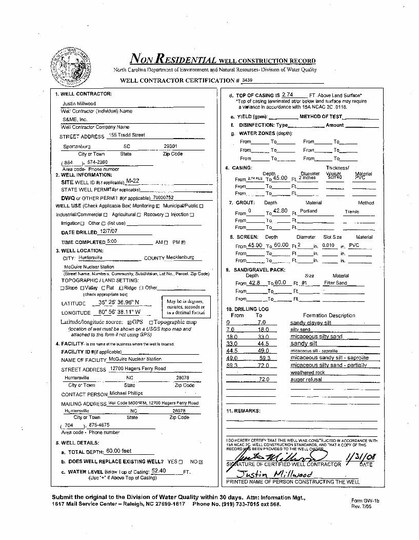
NON RESIDENTIAL WELL CONSTRUCTION RECORD
North Carolina Department of Environment and Natural Resources- Division of Water Quality
WELL CONTRACTOR CERTIFICATION # 3439
1. WELL CONTRACTOR:
Justin Millwood
Well Contractor (Individual) Name
S&ME, Inc.
Well Contractor Company Name
STREET ADDRESS 155 Tradd Street
Spartanburg SC 29301
City or Town State Zip Code
864 ). 574-2360Area code- Phone number
2. WELL INFORMATION:
SITE WELL ID #(if applicable) M-22
STATE WELL PERMIT#(if applicable)
DWQ or OTHER PERMIT #(if applicable) 70000752
WELL USE (Check Applicable Box) Monitoring 91 Municipal/Public El
Industrial/Commercial C Agricultural C Recovery 0 Injection C
Irrigation[3 Other 0 (list use)
DATE DRILLED 12/7/07
TIME COMPLETED 5:00 AM C[ PM e3
3. WELL LOCATION:CITY: Huntersville COUNTY Mecklenburg
McGuire Nuclear Station(Street Name, Numbers, Community, Subdivision, Lot No., Parcel, Zip Code)
TOPOGRAPHIC / LAND SETTING:
oSlope DValley CJFlat f£Ridge 0 Other(check appropriate box)
LATITUDE 350 25' 36.96" N May be in degrees,minutes, seconds or
LONGITUDE 800 56' 38.11" W in a decimal format
Latitude/longitude source: aiGPS C Topographic map(location of well must be shown on a USGS topo map andattached to this form if not using GPS)
4. FACILITY- is the name of the business where the well is located.
FACILITY ID #(if applicable)_
NAME OF FACILITY McGuire-Nuclear Station
STREET ADDRESS 12700 Hagers Ferry Road
Huntersville NC 28078
d. TOP OF CASING IS 2.74 FT. Above Land Surface**Top of casing terminated at/or below land surface may require
a variance in accordance with 15A NCAC 2C .0118.
a. YIELD (gpm): _ METHOD OF TEST
f. DISINFECTION: Type Amount
g. WATER ZONES (depth):
From - To From_ To
From_ To From To_
From_ To_ From_ To
6. CASING: Thickness/Depth Diameter Material
From 2.74ALS TO 45.00 Ft._2 inches c PVC
From To_ Ft._From To Ft.
7. GROUT: Depth Material Method
From 0 To 42.80 Ft. Portland Tremie
From To Ft.
From- To Ft,
8. SCREEN: Depth Diameter Slot Size Material
From 45.00 To 60.00 Ft. 2 in. 0.010 in. PVCFrom To _ Ft. in. _ in.
From_ To_ Ft. in. _ in.
9. SANDIGRAVEL PACK:
Depth Size Material
From 42.8 To 60.0 Ft. #1 Filter Sand
From To Ft._
From To Ft._
10. DRILLING LOGFrom To Formation Description
0 7.0 sandy clayey silt7.0 18.0 silty send18 0 33 0 micaceous silty sand33.0 44.5 sandy silt44.5 49.0 micaceous silt - saprolite
49.0 59.3 micaceous sandy silt - saprolite
5q 3 72 0 micaceous silty sand - partially.. _ _ weathered rock
72.0 auger refusal
11. REMARKS:
I DO HEREBY CERTIFY THAT THIS WELL WAS CONSTRUCTED IN ACCORDANCE WITH15A NCAC 2C, WELL CONSTRUCTION STANDARDS, AND THAT A COPY OF THISRECORDJ BEEN PROVIDED TO THE WELL O•F2
S17 ATURE OF CERTIFIED WELL CONTRACTOR DATE
PRINTED NAME OF PERSON CONSTRUCTING THE WELL
City or Town State Zip Code
CONTACT PERSON Michael Phillips
MAILING ADDRESS Mail Code MG01EM, 12700 Hagers Ferry Road
Huntersville NC 28078
City or Town State Zip Code
704 ._ 875-4675
Area code - Phone number
5. WELL DETAILS:
a. TOTAL DEPTH: 60.00 feet
b. DOES WELL REPLACE EXISTING WELL? YES C NO 2
c. WATER LEVEL Below Top of Casing: 52.40 FT.(Use "+" if Above Top of Casing)
Submit the original to the Division of Water Quality within 30 days. Attn: Information Mgt.,1617 Mail Service Center- Raleigh, NC 27699-1617 Phone No. (919) 733-7015 ext 568. Form GW-1 b
Rev. 7/05

NONIRESIDENTIAL WELL CONSTRUCTION RECORDNorth Carolina Department of Environment and Natural Resources- Division of Water Quality
WELL CONTRACTOR CERTIFICATION # 3439
1. WELL CONTRACTOR:
Justin Millwood
Well Contractor (Individual) Name
S&ME, Inc.
Well Contractor Company Name
STREET ADDRESS 155 Tradd Street
Spartanburg SC 29301
City or Town State Zip Code
864 )- 574-2360Area code- Phone number
2. WELL INFORMATION:
SITE WELL ID #(if applicable) M-22R
STATE WELL PERMIT#0if applicable)
DWQ or OTHER PERMIT #(if applicable) 70000752
WELL USE (Check Applicable Box) Monitoring El Municipal/Public 0
Industrial/Commercial 0 Agricultural 0 Recovery 0 Injection 0
Irrigationo Other 0 (list use)
DATE DRILLED 12/6/07
TIME COMPLETED 5:00 AM E] PM EJ
3. WELL LOCATION:
CITY: Huntersville COUNTY Mecklenburg
McGuire Nuclear Station(Street Name, Numbers, Community, Subdivision, Lot No., Parcel, Zip Code)
TOPOGRAPHIC / LAND SETTING:0Slope DValley oFlat oRidge 0 Other
(check appropriate box)
LATITUDE 350 25' 36.99" N May be in degrees,minutes, seconds or
LONGITUDE 800 56' 38.06" W in a decimal fonnat
Latitude/longitude source: ~i GPS 0 Topographic map(location of well must be shown on a USGS topo map and
attached to this form if not using GPS)
4. FACILITY- is the name of the business where the well is located.
FACILITY ID #(if applicable)
NAME OF FACILITY McGuire Nuclear Station
STREET ADDRESS 12700 Hagers Ferry Road
Huntersville NC 28078
City or Town State Zip Code
CONTACT PERSON Michael Phillips
MAILING ADDRESS Mail Code MG01 EM, 12700 Hagers Ferry RoadHuntersville NC 28078
City or Town State Zip Code704 875-4675
Area code - Phone number
5. WELL DETAILS:
a. TOTAL DEPTH: 92.00 feet
b. DOES WELL REPLACE EXISTING WELL? YES 0 NO [N
c. WATER LEVEL Below Top of Casing: 52.69 FT.(Use "+" if Above Top of Casing)
d. TOP OF CASING IS 2.64 FT. Above Land Surface**Top of casing terminated at/or below land surface may requirea variance in accordance with 15A NCAC 2C .0118.
e. YIELD (gpm): _ METHOD OF TEST
f. DISINFECTION: Type Amount
g. WATER ZONES (depth):
From_ To From- To -
From - To From To_ _
From - To_ From To
6. CASING: Thickness/Depth Diameter 1606 Material
From 2.64ALS To 87.00 Ft._2 inches 4 PVC
From To_ _ Ft._
From_ To__ Ft._
7. GROUT: Depth Material Method
From 0 To 37.80 Ft. Neat Cement Tremie
From_ To_ Ft.
From_ To_ Ft.
8. SCREEN: Depth Diameter Slot Size Material
From 87.00 To 92.0 Ft.2 in. 0.010 in. PVCFrom To_ Ft. in. in.
From To Ft. in. in.
9. SAND/GRAVEL PACK:Depth Size Material
From To Ft.
From To_ Ft.
From To_ Ft._
10. DRILLING LOGFrom To
0 7.0
7.0 18.018,0 330
33,0 44.544.5 49.049.0 59.359 3 720
72.0 95.6
11. REMARKS:
Formation Descriptionsandy clayey siltsilty sandmicaceous silty sandsandy siltmicaceous silt - saprolite
micaceous sandy silt - saprolitemicaceous silty sand - partially weathered rock
medium to coarse orained ouartz diorite
- bentonite placed below well from 92.0 to 95.6 ft BLS- K-packer placed at 86.0 to 86.3 ft BLS; bentonite seal placed at
37.8 to 86.0 feet BLS: no sand/oravel nack below K-Dacker.DOO HEREBY CERTIFY THAT THIS WELL WAS CONSTRUCTED IN ACCORDANCE WITH
15A NCAC 2C, WELL CONSTRUCTION STANDARDS, AND THAT A COPY OF THISRECORD S EEN PROVIDED TO THE WE NER.
S)^ATURE OF CERTIFIED WELL CONTRACTOR I ýOATE
PRINTED NAME OF PERSON CONSTRUCTING THE WELL
Submit the original to the Division of Water Quality within 30 days. Attn: Information Mgt.,1617 Mail Service Center - Raleigh, NC 27699-1617 Phone No. (919) 733-7015 ext 568. Form GW-lb
Rev. 7/05

NON RESIDENTIAL WELL CONSTRUCTION RECORDNorth Carolina Department of Environment and Natural Resources- Division of Water Quality
WELL CONTRACTOR CERTIFICATION # 3439
1. WELL CONTRACTOR:
Justin MillwoodWell Contractor (Individual) Name
S&ME, Inc.
Well Contractor Company Name
STREET ADDRESS 155 Tradd Street
Spartanburg SC 29301
City or Town State Zip Code
864 ). 574-2360
Area code- Phone number2. WELL INFORMATION:
SITE WELL ID #(if applicable) M-23
STATE WELL PERMIT#(if applicable)
DWQ or OTHER PERMIT #(if applicable) 70000752
WELL USE (Check Applicable Box) Monitoring El Municipal/Public [3
Industrial/Commercial [] Agricultural E] Recovery 0 Injection 0
IrrigationE[ Other [I (list use)
DATE DRILLED 11/29/07
TIME COMPLETED 5:00 AM 0 PM El
3. WELL LOCATION:
CITY: Huntersville COUNTY Mecklenburg
McGuire Nuclear Station
(Street Name, Numbers, Community, Subdivision, Lot No., Parcel, Zip Code)TOPOGRAPHIC / LAND SETTING:
ElSlope L-)Valley []Flat D IRidge 0 Other_(check appropriate box)
LATITUDE 35' 25' 39.20" N May be in degrees,minutes, seconds or
LONGITUDE 80' 56' 23.74" W in a decimal forinat
Latitudc/longitudc source: 01 GPS oTopographicmap(location of well must be shown on a USGS topo map andattached to this form if not using GPS).
4. FACILITY- is the name of the business where the well is located.
FACILITY ID #(if applicable)
NAME OF FACILITY McGuire Nuclear Station
STREET ADDRESS 12700 Hagers Ferry Road
Huntersville NC 28078
d. TOP OF CASING IS 2.70 FT. Above Land Surface**Top of casing terminated at/or below land surface may require
a variance in accordance with 15A NCAC 2C .0118.
e. YIELD (gpm): METHOD OF TEST
f. DISINFECTION: Type Amount
g. WATER ZONES (depth):
From - To From To-----
From_ To From To -
From_ To - From_ To
6. CASING: Thickness/Depth Diameter \eightý 4 Material
From 2.70ALS To 32.00 Ft. 2 inches ch 4 PVC
From___ To__ Ft._
From_ To_ Ft._
7. GROUT: Depth Material Method
From 0 To 26.80 Ft. Portland Tremie
From To Ft.
From_ To Ft.
8. SCREEN: Depth Diameter Slot Size Material
From 32.00 To 47.00 Ft. 2 in. 0.010 in. PVCFrom To_ Ft. in. _ in.From To_ _ Ft. in. _ in.
9. SANDIGRAVEL PACK:Depth Size Material
From 29.4 To 48.5 Ft. #1 Filter Sand
From To_ Ft.
From To Ft._
10. DRILLING LOGFrom To Formation Description
0 0.3 topsoil/grass/rootmat0.3 7.0 clayey silt7.0 15 0 micaceous clayey fine sandy silt15.0 27.0 sandy clayey silt27.0 50.9 micaceous silt - saprolite
11. REMARKS:
City or Town State Zip Code
CONTACT PERSON Michael Phillips
MAILING ADDRESS Mail Code MG01EM, 12700 Hagers Ferry Road
Huntersville NC 28078
City or Town State
704 875-4675
Area code - Phone number
Zip Code
5. WELL DETAILS:
a. TOTAL DEPTH: 47.00 feet
b. DOES WELL REPLACE EXISTING WELL? YES 0 NO [2
c. WATER LEVEL Below Top of Casing: 40.64 FT.(Use "+" if Above Top of Casing)
I DO HEREBY CERTIFY THAT THIS WELL WAS CONSTRUCTED IN ACCORDANCE WITH1 5A NCAC 2,, WELL CONSTRUCTION STANDARDS, AND THAT A COPY OF THISRECORDS BEEE PROVIDED TO THE)ELL OW,.
S;9ATURE OF CERTIFIED WELL CONTRACTOR 7-7-ATE
PRINTED NAME OF PERSON CONSTRUCTING THE WELL
Submit the original to the Division of Water Quality within 30 days. Attn: Information Mgt.,1617 Mail Service Center- Raleigh, NC 27699-1617 Phone No. (919) 733-7015 ext 568.
Form GW-lbRev. 7/05
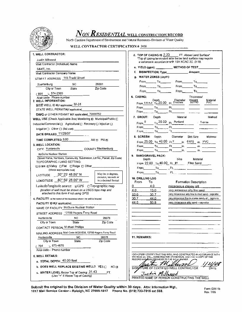
NON RESIDENTIAL WELL CONSTRUCTION RECORDNorth Carolina Department of Environment and Natural Resources- Division of Water Quality
WELL CONTRACTOR CERTIFICATION # 3439
1. WELL CONTRACTOR:
Justin Millwood
Well Contractor (Individual) Name
S&ME, Inc.
Well Contractor Company Name
STREET ADDRESS 155 Tradd Street
Spartanburg SC 29301
City or Town State Zip Code
(864 )- 574-2360
Area code- Phone number2. WELL INFORMATION:
SITE WELL ID #(if applicable) M-31
STATE WELL PERMIT#(if applicable)_
OWQ or OTHER PERMIT #(If applicable) 70000752
WELL USE (Check Applicable Box) Monitoring ID Municipal/Public M2
Industrial/Commercialr1 Agricultural[1 Recovery 1-Injection 1
Irrigation12 Other 12 (list use)
DATE DRILLED 11/28/07
TIME COMPLETED 5:00 AM M PM E]
3. WELL LOCATION:
CITY: Huntersville COUNTY Mecklenburg
McGuire Nuclear Station
(Street Name, Numbers, Community, Subdivision, Lot No., Parcel, Zip Code)
TOPOGRAPHIC / LAND SETTING:
glSlope riValley OFlat flRidge 13 Other(check appropriate box)
LATITUDE 350 25' 48.86" N May be in degrees,minutes, seconds or
LONGITUDE 80' 56' 28.05" W in a decimal fornat
Latitude/longitude source: EilGPS 1 Topographic map(location of welt must be shown on a USGS topo map and
attached to this form if not using GPS)
4. FACILITY- is the name of the business where the well is located.
FACILITY ID #(if applicable)
NAME OF FACILITY McGuire Nuclear Station
STREET ADDRESS 12700 Hagers Ferry Road
Huntersville NC 28078
d. TOP OF CASING IS 2.33 FT. Above Land Surface**Top of casing terminated at/or below land surface may require
a variance in accordance with 15A NCAC 2C .0118.
e. YIELD (gpm): METHOD OF TEST
f. DISINFECTION: Type Amount
g. WATER ZONES (depth):
From_ To_ From - To
From_ To__ From To
From _ To_ From_ To
6. CASING: Thickness/Depth Diameter Wýeight Material
From 2.33ALS To 25.00 Ft. 2 inches ch4 PVC
From_ To Ft._
From_ To Ft._
7. GROUT: Depth Material Method
From 0 To 20.00 Ft. Portland , Tremie
From To_ Ft.
From_ _ To Ft.
B. SCREEN: Depth Diameter Slot Size Material
From 25.00 To 40.00 Ft.2
in. 0.010 in. PVC
From To Ft. in. in.
From To Ft. in. in.
9. SANDIGRAVEL PACK:Depth Size Material
From 22.60 To 40.00 Ft. #1 Filter Sand
From To_ Ft.
From To Ft._
10. DRILLING LOG
From To Formation Description
0 4.0 micaceous clayey silt
4.0 13.0 very micaceous silty fine sand
13.0 30 7 very micaceous silty fine to med sand - saprolite
30.7 44.0 very micaceous fine to coarse sandy silt - saprolite
44.0 50.8 very micaceous silty sand - saprolite
11. REMARKS:
City or Town State Zip Code
CONTACT PERSON Michael Phillips
MAILING ADDRESS Mail Code MG01EM, 12700 Hagers Ferry Road
Huntersville NC 28078City or Town State Zip Code
70_.4 ) 875-4675
Area code - Phone number
5. WELL DETAILS:
a. TOTAL DEPTH: 40.00 feet
b. DOES WELL REPLACE EXISTING WELL? YES 12 NO (A
c. WATER LEVEL Below Top of Casing: 31.43 FT.(Use "+" if Above Top of Casing)
tDO HEREBY CERTIFY THAT THIS WELL WAS CONSTRUCTED IN ACCORDANCE WITH15A NCAC 2C. WELL CONSTRUCTION STANDARDS, AND THAT A COPY OF THISRECORDHA EEN P JOVIDED TO THE WE WNER
SIGG RE OF CERTIFIED WELL CONTRACTOR ATE/ -,7, r* 014&&,
PRINTED NAME OF PERSON CONSTRUCTING THE WELL
Submit the original to the Division of Water Quality within 30 days. Attn: Information Mgt.,1617 Mail Service Center- Raleigh, NC 27699-1617 Phone No. (919) 733-7015 ext 568.
Form GW-lbRev. 7105

NON RESIDENTIAL WELL CONSTRUCTION RECORDNorth Carolina Department of Environment and Natural Resources-Division of Water Quality
WELL CONTRACTOR CERTIFICATION # 3439
1. WELL CONTRACTOR:
Justin MillwoodWell Contractor (Individual) Name
S&ME, Inc.
Well Contractor Company Name
STREET ADDRESS 155 Tradd Street
Spartanburg SC 29301
City or Town State Zip Code
(864 )- 574-2360
Area code- Phone number2. WELL INFORMATION:
SITE WELL ID #(if applicable) M-35
STATE WELL PERMIT#(if applicable)_
DWQ or OTHER PERMIT #(if applicable) 70000752
WELL USE (Check Applicable Box) Monitoring 9) Municipal/Public F1
Industrial/Commercial E3 Agricultural El Recovery El Injection El
Irrigationc Other E- (list use)
DATE DRILLED 12/12/07
TIME COMPLETED 5:00 AM El PM El
3. WELL LOCATION:
CITY: Huntersville COUNTY Mecklenburg
McGuire Nuclear Station
(Street Name, Numbers, Community, Subdivision, Lot No., Parcel, Zip Code)
TOPOGRAPHIC / LAND SETTING:
XISlope UValley ElFIat DRidge El Other(check appropriate box)
LATITUDE 350 25' 44.09" N May be in degrees,ninutcs, seconds or
LONGITUDE 80" 56' 22.20" W in a decimal fonrnat
Latitude/longitude source: E GPS o[Topographicmap(location of well must be shown on a USGS topo map andattached to this form if not using GPS)
4. FACILITY- is the name of the business where the well is located.
FACILITY ID #(if applicable)
NAME OF FACILITY McGuire Nuclear Station
STREET ADDRESS 12700 Hagers Ferry Road
Huntersville NC 28078
d. TOP OF CASING IS 2.47 FT. Above Land Surface**Top of casing terminated at/or below land surface may require
a variance in accordance with 15A NCAC 2C .0118.
e. YIELD (gpm): _ METHOD OF TEST
f. DISINFECTION: Type Amount
g. WATER ZONES (depth):
From_ To From To
From_ To_ From - To
From_ To_ From - To
6. CASING: Thickness/Depth Diameter Vjeight Material
From 2.74 ALS To 15.80 Ft. 2 inches ch 4 PVC
From_ To_ Ft._From- To_ Ft._
7. GROUT: Depth Material Method
From 0 To 9.00 Ft. Portland Tremie
From To Ft.
From____ To Ft.
8. SCREEN: Depth Diameter Slot Size Material
From 15.80 To 30.80 Ft. 2 in. 0.010 in. PVCFrom _ To___ Ft. in. _ in.
From_ To _ Ft. in. _ in.
9. SANDIGRAVEL PACK:Depth Size Material
From 13.00 To 30.80 Ft. #1 Filter Sand
From To_ Ft._
From To Ft._
10. DRILLING LOGFrom To Formation Description
0 0.3 leaves- root mat. topsoil0.3 19.5 silty clay19.5 235 fine sandy silty clay23.5 29.8 micaceous silt - saprolite29.8 31.1 fine to medium sandy silt
31.1 auger refusal
11. REMARKS:
City or Town State Zip Code
CONTACT PERSON Michael Phillips
MAILING ADDRESS Mail Code MG01EM, 12700 Hagers Ferry Road
Huntersville NC 28078
City or Town State
704 )- 875-4675
Area code - Phone number
Zip Code
6. WELL DETAILS:
a. TOTAL DEPTH: 30.80 feet
b. DOES WELL REPLACE EXISTING WELL? YES Dl NO 0
c. WATER LEVEL Below Top of Casing: 25.47 FT.(Use "+" if Above Top of Casing)
I DO HEREBY CERTIFY THAT THIS WELL WAS CONSTRUCTED IN ACCORDANCE WITH1SA NGAC 9, WELL CONSTRUCTION STANDARDS, AND THAT A COPY OF THISRECORgPO5 BEEN PROVIDED TOT WELLOý.
NTERE OFMCERTIFIED WELL CONTRACTOR TEWL
PRINTED NAME OF PERSON CONSTRUCTING THE WELL
Submit the original to the Division of Water Quality within 30 days. Attn: Information Mgt.,1617 Mail Service Center- Raleigh, NC 27699-1617 Phone No. (919) 733-7015 ext 568.
Form GW-lbRev. 7/05

NONRESIDENTIAL WELL CONSTRUCTION RECORDNorth Carolina Department of Environment and Natural Resources- Division of Water Quality
WELL CONTRACTOR CERTIFICATION # 3439
1. WELL CONTRACTOR:
Justin Millwood
Well Contractor (Individual) Name
S&ME, Inc.
Well Contractor Company Name
STREET ADDRESS 155 Tradd Street
Spartanburg SC 29301
City or Town State Zip Code
(864 )- 574-2360
Area code- Phone number2. WELL INFORMATION:
SITE WELL ID #(if applicable) M-60
STATE WELL PERMIT#(if applicable)
DWO or OTHER PERMIT #(if applicable) 70000752
WELL USE (Check Applicable Box) Monitoring [] Municipal/Public M
Industrial/Commercial 0 Agricultural 0 Recovery El Injection 0
IrrigationE] Other 0 (list use)
DATE DRILLED 11/27/07
TIME COMPLETED 5:00 AM o] PM [D
3. WELL LOCATION:
CITY: Huntersville COUNTY Mecklenburg
McGuire Nuclear Station
(Street Name, Numbers, Community, Subdivision, Lot No., Parcel, Zip Code)
TOPOGRAPHIC / LAND SETTING:
USlope OValley &iFlat DRidge 0 Other(check appropriate box)
LATITUDE 35' 26' 02.52" N May be in degrees,minutes, seconds or
LONGITUDE 80* 56' 39.68" W in a decimal fonnat
Latitude/longitude source: oGPS []Topographic map
(location of well must be shown on a USGS topo map andattached to this form if not using GPS)
4. FACILITY- is the name of the business where the well is located.
FACILITY ID #(if applicable)
NAME OF FACILITY McGuire Nuclear Station
STREET ADDRESS 12700 Hagers Ferry Road
Huntersville NC 28078
d. TOP OF CASING IS 2.19 FT. Above Land Surface**Top of casing terminated at/or below land surface may require
a variance in accordance with 15A NCAC 2C .0118.
e. YIELD (gpm): METHOD OF TEST
f. DISINFECTION: Type_ Amount
g. WATER ZONES (depth):
From_ To From_ To
From_ To_ _ From To
From_ To_ _ From_ To
6. CASING: Thickness/Depth Diameter W14eight Material
From_2.19ALS To 24.00 Ft. 2 inches ch 4u PVC
From_ To Ft._
From_ To_ Ft._
7. GROUT: Depth Material Method
From 0 To 18.00 Ft. Portland Tremie
From To Ft.
From _ To_ _ Ft.
8. SCREEN: Depth Diameter Slot Size Material
From 24.00 To 39.00 Ft.2
in. 0.010 in. PVC
From _ To_ Ft. in, _ in.
From_ To Ft. in. _ in.
9. SAND/GRAVEL PACK:Depth Size Material
From 21.60 To 39.00 Ft. #1 Filter Sand
From To _ Ft.
From To Ft._
10. DRILLING LOGFrom To Formation Description
0 0.2 root mat/topsoil
0.2 7.0 micaceous clayey silt70 102 silty fine sand - saprolite10.2 33.0 micaceous fine sandy silt- saprolite33.0 39.8 micaceous silty fine to med sand - saprolite
39 8 auger refusal
11. REMARKS:
City or Town State Zip Code
CONTACT PERSON Michael Phillips
MAILING ADDRESS Mail Code MG01EM, 12700 Hagers Ferry Road
Huntersville NC 28078
City or Town State
704 )- 875-4675
Area code - Phone number
Zip Code
5. WELL DETAILS:
a. TOTAL DEPTH: 39.00 feet
b. DOES WELL REPLACE EXISTING WELL? YES C NO [D
c. WATER LEVEL Below Top of Casing: 31.55 FT.(Use "+" if Above Top of Casing)
I DO HEREBY CERTIFY THAT THIS WELL WAS CONSTRUCTED IN ACCORDANCE WITH15A NCAC .. WELL CONSTRUCTION STANDARDS. AND THAT A COPY OF THISRECOR40AS BEEN PROVIDED TO TWEý,WELL .
SI[A-TURE OF CERTIFIED WELL CONTRACTOR ' DATE
-ST , 1 ".- M ; //W oPRINTED NAME OF PERSON CONSTRUCTING THE WELL
Submit the original to the Division of Water Quality within 30 days. Attn: Information Mgt.,1617 Mail Service Center- Raleigh, NC 27699-1617 Phone No. (919) 733-7015 ext 568.
Form GW-lbRev, 7/05

NON RESIDENTIAL WELL CONSTRUCTION RECORD
North Carolina Department of Environment and Natural Resources- Division of Water Quality
WELL CONTRACTOR CERTIFICATION # 2717
1. WELL CONTRACTOR:
Jay LittleWell Contractor (Individual) Name
S&ME, Inc.Well Contractor Company Name
STREET ADDRESS 9751 Southern Pine Boulevard
Charlotte NC 28273City or Town State Zip Code
(704 - 523-4726Area code- Phone number
2. WELL INFORMATION:
SITE WELL ID #(if applicable) M-91
STATE WELL PERMIT#(if applicable)
DWQ or OTHER PERMIT #(if applicable) 70000752
WELL USE (Check Applicable Box) Monitoring 91 Municipal/Public nI
IndustriallCommercial 0 Agricultural [I Recovery 0] Injection 0]
IrrigationO Other E3 (list use)
DATE DRILLED 1/8/08
TIME COMPLETED 5:00 AM o PM zi
3. WELL LOCATION:
CITY: Huntersville COUNTY Mecklenburg
McGuire Nuclear Station(Street Name, Numbers, Community, Subdivision, Lot No., Parcel, Zip Code)
TOPOGRAPHIC / LAND SETTING:0Slope OValley 0FIat ujRidge 0 Other
(check appropriate box)
LATITUDE 35 25' 54.30" N May be in degrees,minutes, seconds or
LONGITUDE 80 57' 09.13"W in a decimal format
Latitude/longitude source: liGPS oTopographic map(location of well must be shown on a USGS topo map andattached to this form if not using GPS)
4. FACILITY- Is the name of the business where the well Is located.
FACILITY ID #(If applicable)
NAME OF FACILITY McGuire Nuclear Station
STREET ADDRESS 12700 Hagers Ferry Road
Huntersville NC 28078
City or Town State Zip Code
CONTACT PERSON Michael Phillips
MAILING ADDRESS Mail Code MG01EM, 12700 Hagers Ferry Rd
Huntersville NC 28078City or Town State Zip Code
704 ) 875-4675Area code - Phone number
S. WELL DETAILS:
a. TOTAL DEPTH: 39.00 ft
b. DOES WELL REPLACE EXISTING WELL? YES 0 NO Z]
c. WATER LEVEL Below Top of Casing: 31.55 FT.(Use +" if Above Top of Casing)
d. TOP OF CASING IS 3.05 FT. Above Land Surface**Top of casing terminated at/or below land surface may require
a variance in accordance with 15A NCAC 2C .0118.
a. YIELD (gpm): METHOD OF TEST
f. DISINFECTION: Type_ _ Amount
g. WATER ZONES (depth):
From_ To__ From To
From_ To_ From_ To
From_ To_ _ From_ To
6. CASING: Thickness/Depth Diameter Weihgzt Overial
From 3.05 ALS To 24.50 1Ls Ft. 2 inches
From - To_ Ft._
From - To_ Ft._
7. GROUT: Depth Material Method
From 0 To 20.00 Ft. Portland Tremie
From To Ft.
From _ To_ Ft.
8. SCREEN: Depth Diameter Slot Size Material
From 24.00 To 39.00 Ft.2 in. 0.010 in. PVCFrom__ _ To_ _ Ft. in. in.From _ To _ Ft. in. in.
9. SANDIGRAVEL PACK:
Depth Size Material
From 22.00 To 39.00 Ft. #1 1 Filter Sand
From To_ Ft.
From To Ft._
10. DRILLING LOGFrom To Formation Description
0 0.3 grass, root mat0.3 8.0 micaceous sandy clayey silt8-0 13.0 alluvium-micaceous silty clay13.0 18.0 micaceous clayey silt18.0 28,0 mottled micaceous ait28.0 39.0 fine sandy silt
11. REMARKS:
I DO HEREBY CERTIFY THAT THIS WELL WAS CONSTRUCTED IN ACCORDANCE WITH15A NCAC 2C, WELL CONSTRUCTION STANDARDS, AND THAT A COPY OF THISRECORD I1ýS BEEN PROVIDED TO THE WELL OWNER.
,S NATUI, OF CERTIFIED WELL CONTRACTOR DATE
PRINTED NAME OF PERSON CONSTRUCTING THE WELL
Submit the original to the Division of Water Quality within 30 days. Attn: Information Mgt,1617 Mail Service Center- Raleigh, NC 27699-1617 Phone No. (919) 733-7015 ext568.
Form GW-1 bRev. 7/05

NON RESIDENTIAL WELL CONSTRUCTION RECORD
North Carolina Department of Environment and Natural Resources- Division of Water Quality
WELL CONTRACTOR CERTIFICATION # 2717
1. WELL CONTRACTOR:
Jay LittleWell Contractor (Individual) Name
S&ME, Inc.Well Contractor Company Name
STREET ADDRESS 9751 Southern Pine Boulevard
Charlotte NC 28273City or Town State Zip Code
(704 '.. 523-4726Area code- Phone number
2. WELL INFORMATION:
SITE WELL ID #(if applicable) M-91 R
STATE WELL PERMIT#(lf applicable)
DWQ or OTHER PERMIT #(if applicable) 70000752
WELL USE (Check Applicable Box) Monitoring XI Municipal/Public 0
IndustrialVCommercial ni Agricultural 0 Recovery 0 Injection 0i
IrrigationO Other El (list use)
DATE DRILLED 1/2/07
TIME COMPLETED 5:00 AM [] PM 3]
3. WELL LOCATION:
CITY: Huntersville COUNTY Mecklenburg
McGuire Nuclear Station(Street Name, Numbers, Community, Subdivision, Lot No., Parcel, Zip Code)
TOPOGRAPHIC / LAND SETTING:
O3SIope DValley ]Flat URidge ci Other(check appropriate box)
LATITUDE 35 25' 54.30" N May be in degrees,minutes, seconds or
LONGITUDE 80 57' 09.20"W in a decimal format
Latitude/longitude source: u GPS ri Topographic map(location of well must be shown on a USGS topo map andattached to this form if not using GPS)
4. FACILITY- is the name of the business where the well Is located.
FACILITY ID #(if applicable)
NAME OF FACILITY McGuire Nuclear Station
STREET ADDRESS 12700 Hagers Ferry Road
Huntersville NC 28078
d. TOP OF CASING IS 2.87 FT. Above Land Surface*
*Top of casing terminated at/or below land surface may require
a variance in accordance with 15A NCAC 2C .0118.
e. YIELD (gpm): METHOD OF TEST
f. DISINFECTION: Type Amount
g. WATER ZONES (depth):
From To From To
From_ To _ From_ To
From_ To_ From_ To_
6. CASING: Thickness/Depth Diameter VWeight atrial
From 2.87ALS To 53.o0 Us Ft. 2 inches ch4 V
From_ To_ Ft._From_ To _ Ft._
7. GROUT: Depth Material Method
From 0 To 22.40 Ft. Portland Tremie
From_ To_ Ft.From_ To Ft.
8. SCREEN: Depth Diameter Slot Size Material
From 53.00 To 63.00 Ft. 2 in. 0.010 in. PVCFrom To Ft. in. in.From_ To Ft. in. in.
9. SANDIGRAVEL PACK:
Depth Size Material
From To_ Ft,
From To_ Ft.
From To_ Ft.
10. DRILLING LOGFrom To
0 0.30.3 8.08.0 13ý013.0 18.018.0 28.028.0 525
52.552.5 69.8
Formation Descriptiongrass, rootmatmicaceous sandy clayey siltalluvium-micaceous silty claymicaceous clayey siltmottled micaceous silt
micaceous fine sandy silt
City or Town State Zip Code
CONTACT PERSON Michael Phillips
MAILING ADDRESS Mail Code MG01EM, 12700 Hagers Ferry Rd
Huntersville NC 28078
refusal to roller cone bitmedium grained quartz dioritewith fractures
City or Town State
704 -875-4675Area code - Phone number
Zip Code
5. WELL DETAILS:
a. TOTAL DEPTH: 63.00 ft
b. DOES WELL REPLACE EXISTING WELL? YES 0i NO 91
c. WATER LEVEL Below Top of Casing: 44.47 FT.(Use "+" if Above Top of Casing)
11. REMARKS:- bentonite placed below well from 64.0 to 69.8 ft BLS; sand placed at 63.0 to 64.0 it BLS
- K-packer placed at 52.5 to 52.7 ft BLS; bentonite seal placed at
22.4 to 52.5 ft BLS; no sand/gravel pack below K-packerI DO HEREBY CERTIFY THAT THIS WELL WAS CONSTRUCTED IN ACCORDANCE WITH15A NCAC 2C, WELL CONSTRUCTION STANDARDS, AND THAT A COPY OF THISRECORD /AS BEEN PROVIDED TO THE WELL OWNER.
.$IGNWA41RE OF CERTIFI'ED WELL CONTRACTOR DATE
PRINTED'NAME OF PERSON CONSTRUCTING THE WELL
i:
Submit the original to the Division of Water Quality within 30 days. Attn: Information Mgt.,1617 Mail Service Center- Raleigh, NC 27699-1617 Phone No. (919) 733-7015 ext 568. Form GW-1 b
Rev. 7/05
SS&ME
February 4, 2008
North Carolina Department of Environment and Natural ResourcesDivision of Water Quality1617 Mail Service CenterRaleigh, North Carolina 27699-1617
Reference: Non-Residential Well Construction Records - Submittal #5Mcguire Nuclear Station12700 Hagers Ferry RoadHuntersville, North CarolinaS&ME Project No. 1264-06-724
Ladies and Gentlemen:
On behalf of Duke Energy, S&ME, Inc. (S&ME) is submitting the enclosed completed andsigned Non-Residential Well Construction Records for the following eleven (11) groundwatermonitoring wells installed at the McGuire Nuclear Station (MNS) site:
* M-20 • M-22 • M-31 • M-91* M-20R • M-22R • M-35 • M-91R.* M-21 * M-23 • M-60
Duke Energy has voluntarily installed groundwater monitoring wells at MNS as part of a site-wide hydrogeologic evaluation. As of this writing, the above eleven (11) wells represent the lastplanned wells for this project at MNS. Therefore, we anticipate this submittal (Submittal #5) tobe the last for this project.
On behalf of Duke Energy, S&ME thanks you for your receipt of these records. Should youhave any questions or need additional information, please contact us.
Sincerely,S&ME, Inc.
Mary Beth Cline, E.I.T. Larr r strong, P.E.
Staff Professional nior Egineer/Project Director
enclosures
cc: Messrs. Greg Robison, Ed Sullivan, Tim Hunsucker; Duke Energy
S.'ENVIROM2006\1264 Projects.\6406724 McGuire Nuclear Groundwater Study\NCDENR Well Records'vcdenr well records submittal doc
S&ME, INC. / 155 Tradd Street / Spartanburg, SC 29301 I p 864.574.2360 f 864.576.87301 Marcus Drive, Suite 301 / Greenville, SC 29615 / p 864-232-8987 / wwwsmeinc.com

NON RESIDENTIAL WELL CONSTRUCTION RECORDNorth Carolina Department of Environment and Natural Resources- Division of Water Quality
WELL CONTRACTOR CERTIFICATION # 2717
1. WELL CONTRACTOR:
Jay LittleWell Contractor (Individual) Name
S&ME, Inc.Well Contractor Company Name
STREET ADDRESS 9751 Southern Pine Boulevard
Charlotte NC 28273City or Town State Zip Code
(704 -. 523-4726Area code- Phone number
2. WELL INFORMATION:
SITE WELL ID #(If applicable) M-20
STATE WELL PERMIT#(if applicable)
DWQ or OTHER PERMIT #(if applicable) 70000752
WELL USE (Check Applicable Box) Monitoring gi Municipal/Public 0
IndustrialfCommercial 12 Agricultural 0 Recovery D Injection 0
Irrigationo Other 03 (list use)
DATE DRILLED 12/11/07
TIME COMPLETED 5:00 AM 0 PM El
3. WELL LOCATION:
CITY: Huntersville COUNTY Mecklenburg
McGuire Nuclear Station(Street Name, Numbers, Community, Subdiision, Lot No., Parcel, Zip Code)
TOPOGRAPHIC I LAND SETTING:
OSIope E-Valley OFlat URidge [] Other(check appropriate box)
LATITUDE 35 25' 36.52" N May be in degrees,minutes, seconds or
LONGITUDE 80 57' 10.43"W in a decimal format
Latitude/longitude source: X)GPS DTopographic map(location of well must be shown on a USGS topo map andattached to this form if not using GPS)
4. FACILITY- is the name of the business where the well is located.
FACILITY ID #(If applicable)
NAME OF FACILITY McGuire Nuclear Station
STREET ADDRESS 12700 Hagers Ferry Road
Huntersville NC 28078City or Town State Zip Code
CONTACT PERSON Michael Phillips
MAILING ADDRESS Mail Code MG01 EM, 12700 Hagers Ferry Rd
Huntersville NC 28078City or Town State Zip Code
704 . 875-4675
Area code - Phone number
5. WELL DETAILS:
a, TOTAL DEPTH: 48.00 ft
b. DOES WELL REPLACE EXISTING WELL? YES [ NO 91
c. WATER LEVEL Below Top of Casing: 41.17 FT.(Use '+" if Above Top of Casing)
d. TOP OF CASING IS 2.96 FT. Above Land Surface**Top of casing terminated at/or below land surface may require
a variance in accordance with 15A NCAC 2C .0118.
e. YIELD (gpm): METHOD OF TEST
f. DISINFECTION: Type_ _ Amount
g. WATER ZONES (depth):
From _ To__ From_ To___
From To From To
From _ To _ From_ To
6. CASING: Thickness/Depth Diameter Jig0 h Oataial
From 2.96 ALS To 33.00 RLS Ft. 2 inches ch4
From, To_ Ft._
From - To_ Ft._
7. GROUT: Depth Material Method
From 0 To_29.00 Ft. Portland Tremie
From To Ft.
From___ To Ft.
8. SCREEN: Depth Diameter Slot Size Material
From 33.00 To 48.00 Ft.2 in. 0.010 in. PVCFrom_ To Ft. in. in.
From -. To__ Ft. in. in.
9. SANDIGRAVEL PACK:Depth Size Material
From 31.00 To48-00 Ft. #1 Filter Sand
From To_ Ft._
From To_ Ft.
10. DRILLING LOGFrom To Formation Description
0 0.3 grass/rootmatltoosoil0-3 13.0 fine sandy silty clay
13 Cl 17-0 slightly clayey fine sandy silt17.0 23.0 silty fine sand23.0 37.0 slightly micaceous fine sandy silt
37-0 490 rmicaceous silty fine sand
4.q0 5n3 micaceous silty fine sand-weathered rock52.3 roller cone bit refusal
11. REMARKS:
DO HEREBY CERTIFY THAT THIS WELL WAS CONSTRUCTED IN ACCORDANCE WITHISA NCAC 2C, WELL CONSTRUCTION STANDARDS, AND THAT A COPY OF THISRECORD HAS BEEN PROVIDED TO THE WELL OWNER,
>•IlNAT3URE OF CERTIFIED WELL CONTRACTOR DATE
PRINTED NUE OF PERSON CONSTRUCTING THE WELL
Submit the original to the Division of Water Quality within 30 days. Attn: Information Mgt.,1617 Mail Service Center- Raleigh, NC 27699-1617 Phone No. (919) 733-7015 ext 568.
Form GW- lbRev. 7/05

NONRESIDENTIAL WELL CONSTRUCTION RECORD
North Carolina Department of Environment and Natural Resources- Division of Water Quality
WELL CONTRACTOR CERTIFICATION # 2717
1. WELL CONTRACTOR:
Jay LittleWell Contractor (Individual) Name
S&ME, Inc.Well Contractor Company Name
STREET ADDRESS 9751 Southern Pine Boulevard
Charlotte NC 28273City or Town State Zip Code
(704 - 523-4726Area code- Phone number
2. WELL INFORMATION:
SITE WELL ID #(if applicable) M-20R
STATE WELL PERMIT#(if applicable)
DWQ or OTHER PERMIT #(if applicable) 70000752
WELL USE (Check Applicable Box) Monitoring CD Municipal/Public 0
Industrial/Commercial [I Agricultural El Recovery El Injection El
Irrigation[ Other [3 (list use)
DATE DRILLED 12/10/07
TIME COMPLETED 5:00 AM [I PM [!
3. WELL LOCATION:
CITY: Huntersville COUNTY Mecklenburg
McGuire Nuclear Station(Street Name, Numbers, Community, Subdivision. Lot No., Parcel, Zip Code)
TOPOGRAPHIC 1 LAND SETTING:
ESiope ElValley ElFiat URidge El Other(check appropriate box)
LATITUDE 35 25' 36.50" N May be in degrees,minutes, seconds or
LONGITUDE 80 57' 10.36"W in a decimal format
Latitude/longitude source: ;OGPS El Topographic map(location of well must be shown on a USGS topa map andattached to this form if not using GPS)
4. FACILITY- is the name of the business where the wall is located.
FACILITY ID #(if applicable)
NAME OF FACILITY McGuire Nuclear Station
STREET ADDRESS 12700 Hagers Ferry RoadHuntersville NC 28078
d. TOP OF CASING IS 2.94 FT. Above Land Surface**Top of casing terminated at/or below land surface may require
a variance in accordance with 15A NCAC 2C .0118.
e. YIELD (gpm): METHOD OF TEST
f. DISINFECTION: Type _ Amount
g. WATER ZONES (depth):
From To From To
From_ To___ From_ To
From. To_ From_ To
6. CASING: Thickness/Depth Diameter weIght• v atrial
From 2.94 ALS To 62.40 Bss Ft. 2 inches ch4
From _ To _ Ft._
From__ _ To_ _ Ft._
7. GROUT: Depth Material MethodFrom 0 To 59.92 Ft. Portland Tremie
From To Ft.
From _ To__ Ft.
8. SCREEN: Depth Diameter Slot Size Material
From 62.49 To 67.49 Ft.2 in. 0.010 in. PVCFrom_ _ To___ Ft. in. in.
From_ To Ft. in. in.
9. SANDIGRAVEL PACK:Depth Size Material
From To_ Ft._
From To_ _ Ft._
From To Ft._
10. DRILLING LOGFrom To
0 0.30.3 13.0
130 17-0
17.0 23.0
23.0 37.0
37.0 49.0
4q n 523
52.3 75.0
Formation Descriptiongrass/rootmat/tonsoi!fine sandy siltv clayslightly clayey fine sandy siltsiltv fine sandslightly micaceous fine sandy silt
micaceous silty fine sandmicaceous silty fine sand-weathered rock
medium to coarse grained quartz dioriteCity or Town State Zip Code
CONTACT PERSON Michael Phillips
MAILING ADDRESS Mail Code MG01 EM, 12700 Hagers Ferry Rd
Huntersville NC 28078City or Town State Zip Code
704 ). 875-4675
Area code - Phone number
5. WELL DETAILS:
a. TOTAL DEPTH: 67.49 ft
b. DOES WELL REPLACE EXISTING WELL? YES El NO EI
c. WATER LEVEL Below Top of Casing: 38.97 FT.(Use "+" if Above Top of Casing)
11. REMARKS:- bentonite placed below well from 70.0 to 75 ft BLS; sand placed at 67.49 to 70 ft BLS
I - K-packer placed at 61.92 to 62.09 ft BLS; bentonite seal placed at59.92 to 61.92 ft BLS; no sand/gravel pack below K-packerI 00 HEREBY CERTIFY THAT THIS WELL WAS CONSTRUCTED IN ACCORDANCE WITH15A NCAC 2C, WELL CONSTRUCTION STANDARDS, AND THAT A COPY OF THISRECORD HA BEEN PROVIDED TO THE WELL OWNER,
( /2.-AASIITUUI OF CERTIFIED WELL CONTRACTOR DATE
PRINTEY NAME OF PERSON CONSTRUCTING THE WELL
Submit the original to the Division of Water Quality within 30 days. Attn: Information Mgt.,1617 Mail Service Center- Raleigh, NC 27699-1617 Phone No. (919) 733-7015 ext 568.
Form GW-1 bRev. 7105

NON RESIDENTIAL WELL CONSTRUCTION RECORDNorth Carolina Department of Environment and Natural Resources- Division of Water Quality
WELL CONTRACTOR CERTIFICATION # 2717
1. WELL CONTRACTOR:
Jay LittleWell Contractor (Individual) Name
S&ME, Inc.Well Contractor Company Name
STREET ADDRESS 9751 Southern Pine Boulevard
Charlotte NC 28273City or Town State Zip Code
(704 . 523-4726Area code- Phone number
2. WELL INFORMATION:
SITE WELL ID #(if applicable) M-21
STATE WELL PERMIT#(if applicable)_
DWQ or OTHER PERMIT #(if applicable) 70000752
WELL USE (Check Applicable Box) Monitoring zj Municipal/Public [I
Industrial/Commercial 0 Agricultural 0 Recovery C Injection El
Irrigation[ Other 0 (list use)
DATE DRILLED 12/12/07
TIME COMPLETED 5:00 AM [3 PM Ei
3. WELL LOCATION:
CITY: Huntersville COUNTY Mecklenburg
McGuire Nuclear Station
(Street Name, Numbers, Community, Subdivision, Lot No., Parcel, Zip Code)TOPOGRAPHIC I LAND SETTING:
r- Slope oValley [3Flat :0]Ridge 0 Other(check appropriate box)
LATITUDE 35 25' 35.69" N May be in degrees,minutes, seconds or
LONGITUDE 80 56' 48.59"W in a decimal format
Latitude/longitude source: uGPS oTopographic map(location of well must be shown on a USGS topo map andattached to this form if not using GPS)
4. FACILITY- is the name of the business where the well is located.
FACILITY ID #(if applicable)_
NAME OF FACILITY McGuire Nuclear Station
STREET ADDRESS 12700 Hagers Ferry Road
Huntersville NC 28078
d. TOP OF CASING IS 2.94 FT. Above Land Surface*Top of casing terminated at/or below land surface may require
a variance in accordance with 15A NCAC 2C .0118.
e, YIELD (gpm): METHOD OF TEST
f. DISINFECTION: Type Amount
g. WATER ZONES (depth):
From __ To _ From___ To
From_ To _ From_ To
From_ To_ From_ To
6. CASING: ThicknesstDepth Diameter Weight aVeial
From 2.05 ALS To 3sOuseLS Ft. 2 inches ch4
From_ To - Ft._
From - To - FL_
7. GROUT: Depth Material Method
From- 0 To_24.00 Ft. Portland Tremie
From - To_ Ft._
From_ To_ Ft._
8. SCREEN: Depth Diameter Slot Size Material
From 30.00 To 50.00 Ft. 2 in. 0.010 in. PVCFrom_ To Ft. in. _ in.
From_ To - Ft. in. _ in.
9. SANDIGRAVEL PACK:
Depth Size Material
From 27.00 To 50.20 Ft. #1 Filter Sand
From To_ Ft._
From To Ft._
10. DRILLING LOGFrom To Formation Description
0 40.38 clayey silt40.38 50.50 micaceous silty sand
11. REMARKS:
City or Town State Zip Code
CONTACT PERSON Michael Phillips
MAILING ADDRESS Mail Code MIIG01EM, 12700 Hagers Ferry Rd
Huntersville NC 28078City or Town State Zip Code
704 . 875-4675
Area code - Phone number
5. WELL DETAILS:
a. TOTAL DEPTH: 50.00 ft
b. DOES WELL REPLACE EXISTING WELL? YES 0 NO 91
c. WATER LEVEL Below Top of Casing: 38.77 FT.(Use '+" if Above Top of Casing)
I DO HEREBY CERTIFY THAT THIS WELL WAS CONSTRUCTED IN ACCORDANCE WITHISA NCAC 2C, WELL CONSTRUCTION STANDARDS, AND THAT A COPY OF THISRECORD"J1S BEEN PROVIDED TOTHE WELL OWNER.
IATE OF CERTIFIED WELL CONTRACTOR DATE
PRINTED4AME OF PERSON CONSTRUCTING THE WELL
Submit the original to the Division of Water Quality within 30 days. Attn: Information Mgt.,1617 Mail Service Center - Raleigh, NC 27699-1617 Phone No. (919) 733-7015 ext 568. Form GW-lb
Rev. 7/05

NON RESIDENTIAL WELL CONSTRUCTION RECORD
North Carolina Department of Environment and Natural Resources- Division of Water Quality
WELL CONTRACTOR CERTIFICATION # 3439
1. WELL CONTRACTOR:
Justin Millwood
Well Contractor (Individual) Name
S&ME, Inc.Well Contractor Company Name
STREET ADDRESS 155 Tradd Street
Spartanburg SC 29301City or Town State Zip Code
864 )- 574-2360Area code- Phone number
2. WELL INFORMATION:
SITE WELL ID #(if applicable) M-22
STATE WELL PERMIT#(if applicable).
DWQ or OTHER PERMIT #(if applicable) 70000752
WELL USE (Check Applicable Box) Monitoring El Municipal/Public 0
Industrial/Commercial 0 Agricultural [I Recovery Ei Injection El
Irrigation U Other EI (list use)
DATE DRILLED 12/7/07
TIME COMPLETED 5:00 AM C1 PM [!
3. WELL LOCATION:
CITY: Huntersville COUNTY Mecklenburg
McGuire Nuclear Station(Street Name, Numbers, Community, Subdivision, Lot No., Parcel, Zip Code)
TOPOGRAPHIC / LAND SETTING:
LjSlope DValley E Flat l]Ridge 0 Other(check appropriate box)
LATITUDE 350 25' 36.96" N May be in degrees,minutes, seconds or
LONGITUDE 80_ 56' 38.11" W in a decimal fonnat
Latitude/longitude source: EjGPS []Topographic map(location of well must be shown on a USGS topo map andattached to this form if not using GPS)
4. FACILITY- is the name of the business where the well is located.
FACILITY ID #(if applicable)
NAME OF FACILITY McGuire Nuclear Station
STREET ADDRESS 12700 Hagers Ferry Road
Huntersville NC 28078
City or Town State Zip Code
CONTACT PERSON Michael Phillips
MAILING ADDRESS Mail Code MG01EM, 12700 Hagers Ferry Road
Huntersville NC 28078
City or Town State Zip Code
704 ). 875-4675
Area code - Phone number
5. WELL DETAILS:
a. TOTAL DEPTH: 60.00 feet
b. DOES WELL REPLACE EXISTING WELL? YES b NO [
c. WATER LEVEL Below Top of Casing: 52.40 FT.(Use "+" if Above Top of Casing)
d. TOP OF CASING IS 2.74 FT. Above Land Surface**Top of casing terminated at/or below land surface may require
a variance in accordance with 15A NCAC 2C .0118.
e. YIELD (gpm): METHOD OF TEST
f. DISINFECTION: Type Amount
g. WATER ZONES (depth):
From To From To
From _ To_ From To
From_ To_ From_ To_
6. CASING: Thickness/Depth Diameter Weight Material
From 2.74ALS To 4 5 .00 Ft, 2 inches ch4 PVC
From_ To_ Ft. _ _
From . To_ Ft. _ _
7. GROUT: Depth Material Method
From- 0 To 42.80 Ft. Portland Tremie
From To Ft.
From_ _ To Ft.
8. SCREEN: Depth Diameter Slot Size Material
From 45.00 To 60.00 Ft.2 in. 0.010 in. PVCFrom__ To__ Ft. in. in.
From____ To _ Ft. in. in.
9. SANDIGRAVEL PACK:Depth Size Material
From 42.8 To 60.0 Ft. #1 Filter Sand
From To_ Ft._
From To Ft._
10. DRILLING LOGFrom To Formation Description
0 7.0 sandy clayey silt
7.0 18.0 silty sand18.0 330 micaceous silty sand33.0 44.5 sandy silt44.5 49.0 micaceous silt - saprolite49.0 59.3 micaceous sandy silt - saprolite5.3 72 0 micaceous silty sand - partially
weathered rock
72.0 augqer refusal
11. REMARKS:
I DO HEREBY CERTIFY THAT THIS WELL WAS CONSTRUCTED IN ACCORDANCE WITHI5A NCAC 2C, WELL CONSTRUCTON STANDARDS, AND THAT A COPY OF THISRECORD~ BEEN PROVIDED TO THE WELL
SI ATURE OF CERTIFIED WELL CONTRACTOR 'DATE
PRINTED NAME OF PERSON CONSTRUCTING THE WELL
Submit the original to the Division of Water Quality within 30 days. Attn: Information Mgt.,1617 Mail Service Center- Raleigh, NC 27699-1617 Phone No. (919) 733-7015 ext568. Form GW-1 b
Rev. 7)05
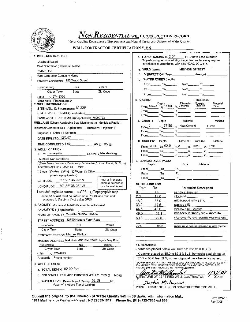
NoN RESIDENTIAL WELL CONSTRUCTION RECORDNorth Carolina Department of Environment and Natural Resources- Division of Water Quality
WELL CONTRACTOR CERTIFICATION # 3439
1. WELL CONTRACTOR:
Justin Millwood
Well Contractor (Individual) Name
S&ME, Inc.
Well Contractor Company Name
STREET ADDRESS 155 Tradd Street
Spartanburg SC 29301
City or Town State Zip Code
864 )- 574-2360Area code- Phone number
2. WELL INFORMATION:
SITE WELL ID #(if applicable) M-22R
STATE WELL PERMIT#(if applicable)
DWQ or OTHER PERMIT #(if applicable) 70000752
WELL USE (Check Applicable Box) Monitoring 2J Municipal/Public E]
Industrial/Commercial 0 Agricultural o Recovery [ Injection 0
Irrigation[] Other 0 (list use)
DATE DRILLED 12/6/07
TIME COMPLETED 5:00 AM 0 PM Ei
3. WELL LOCATION:
CITY: Huntersville COUNTY Mecklenburg
McGuire Nuclear Station
IStreet Name, Numbers, Community, SubdiVsion, Lot No., Parcel, Zip Code)TOPOGRAPHIC / LAND SETTING:
[ESlope DValley O]Flat ORidge 0 Other(check appropriate box)
LATITUDE 350 25' 36.99" N May be in degrecs,minutes, seconds or
LONGITUDE 80' 56' 38.06" W in a decimal fonnat
Latitude/longitude source: rGPS oTopographic map
(location of well must be shown on a USGS topo map andattached to this form if not using GPS)
4. FACILITY- is the name of the business where the well is located.
FACILITY ID #(if applicable)
NAME OF FACILITY McGuire Nuclear Station
STREET ADDRESS 12700 Hagers Ferry Road
Huntersville NC 28078
d. TOP OF CASING IS 2.64 FT. Above Land Surface**Top of casing terminated at/or below land surface may require
a variance in accordance with 15A NCAC 2C .0118.
e. YIELD (gpm): METHOD OF TEST
f. DISINFECTION: Type Amount
g. WATER ZONES (depth):
From -_ To_ From_ To
From_ To_ From_ To
From_ To_ From To_
6. CASING: Thickness/Depth Diameter VeghS Material
From 2.4 ALS To 87.00 Ft. 2 inches ch 4 PVC
From_ To_ Ft._
From_ To_ Ft._
7. GROUT: Depth Material Method
From 0 To 37.80 Ft. Neat Cement Tremie
From_ To_ Ft.
From_ To _ Ft.
8. SCREEN: Depth Diameter Slot Size Material
From 87.00 To 92.0 Ft. 2 in. 0.010 in. PVCFrom To_ Ft. in. _ in.
From To_ _ Ft. in. _ in.
9. SANDIGRAVEL PACK:Depth Size Material
From To __ Ft.
From To_ Ft.
From To _ Ft._
10. DRILLING LOGFrom To Formation Description
0 7.0 sandy clayey silt70 18.0 silty sand18.0 33 0 micaceous silty sand33,0 44.5 sandy silt44.5 49.0 micaceous silt - saprolite49.0 59.3 micaceous sandy silt - saprolite5.9 3 72 0 micaceous silty sand - partially weathered rock
72.0 95.6 medium to coarse grained quartz diorite
11. REMARKS:- bentonite placed below well from 92.0 to 95.6 ft BLS- K-packer placed at 86.0 to 86.3 ft BLS; bentonite seal placed at
37.8 to 86.0 feet BLS: no sand/oravel oack below K-Dacker.
City or Town State Zip Code
CONTACT PERSON Michael Phillips
MAILING ADDRESS Mail Code MG01EM, 12700 Hagers Ferry Road
Huntersville NC 28078City or Town State Zip Code
704 875-4675
Area code - Phone number
5. WELL DETAILS:
a. TOTAL DEPTH: 92.00 feet
b. DOES WELL REPLACE EXISTING WELL? YES 0 NO IN
c. WATER LEVEL Below Top of Casing: 52.69 FT.(Use "+" if Above Top of Casing)
I DO HEREBY CERTIFY THAT THIS WELL WAS CONSTRUCTED IN ACCORDANCE WITH15A NCAC 2C. WELL CONSTRUCTION STANDARDS, AND THAT A COPY OF THISREC ORDAS BEEN PROVIDED TO THE WEL WNER
'S, ATURE OF CERTIFIED WELL CONTRACTOR - ,OATE
3"•W75,,t M~'; I1.'a.• ifPRINTED NAME OF PERSON CONSTRUCTING THE WELL
Submit the original to the Division of Water Quality within 30 days. Attn: Information Mgt.,1617 Mail Service Center- Raleigh, NC 27699-1617 Phone No. (919) 733-7015 ext 568.
Form GW-1 bRev. 7/05
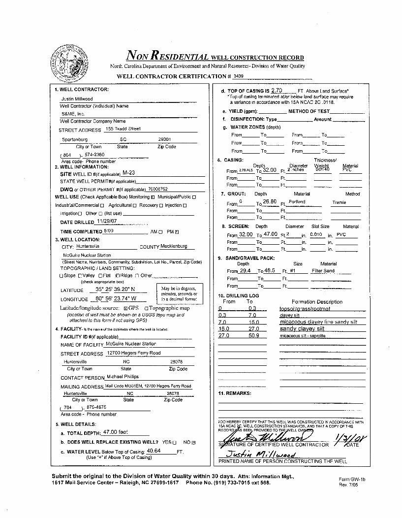
NON RESIDENTIAL WELL CONSTRUCTION RECORDNorth Carolina Department of Environment and Natural Resources- Division of Water Quality
WELL CONTRACTOR CERTIFICATION # 3439
1. WELL CONTRACTOR:
Justin Millwood
Well Contractor (Individual) Name
S&ME, Inc.
Well Contractor Company Name
STREET ADDRESS 155 Tradd Street
Spartanburg SC 29301
City or Town State Zip Code
864 )- 574-2360
Area code- Phone number2. WELL INFORMATION:
SITE WELL ID #(if applicable) M-23STATE WELL PERMIT#(if applicable)
DWQ or OTHER PERMIT #(if applicable) 70000752
WELL USE (Check Applicable Box) Monitoring EJ Municipal/Public 0
Industrial/Commercial E] Agricultural 0 Recovery C Injection E0
Irrigation[] Other 0 (list use)
DATE DRILLED 11/29/07
TIME COMPLETED 5:00 AM 0 PM El
3. WELL LOCATION:
CITY: Huntersville COUNTY Mecklenburg
McGuire Nuclear Station
(Street Name, Numbers, Community, Subdivsion, Lot No., Parcel, Zip Code)TOPOGRAPHIC / LAND SETTING:
ErSlope ElValley E]Flat f]Ridge 0 Other(check appropriate box)
LATITUDE 350 25' 39.20" N May be in degrees,minutes, seconds or
LONGITUDE 80' 56' 23.74" W in a decimal format
Latitude/longitude source: riGPS ciTopographic map(location of well must be shown on a USGS topo map andattached to this form if not using GPS)
4. FACILITY- is the name of the business where the well is located.
FACILITY ID #(if applicable)
NAME OF FACILITY McGuire Nuclear Station
STREET ADDRESS 12700 Hagers Ferry Road
Huntersville NC 28078
d. TOP OF CASING IS 2.70 FT. Above Land Surface**Top of casing terminated atlor below land surface may require
a variance in accordance with 15A NCAC 2C .0118.
e. YIELD (gpm): _ METHOD OF TEST
f. DISINFECTION: Type Amount
g. WATER ZONES (depth):
From_ To From To_
From_ To From_ To
From_ To From To
6. CASING: Thickness/Depth Diameter Wýeight Material
From 2.70 ALS To 32.00 Ft. 2 inches ch 4 PVC
From_ To_ Ft._From_ To_ Ft._
7. GROUT: Depth Material Method
From 0 To_26.80 Ft. Portland Tremie
From To Ft.
From _ To_ _ Ft.
8. SCREEN: Depth Diameter Slot Size Material
From 32.00 To 47.00 Ft.2 in. 0.010 in. PVCFrom_ To _ Ft. in. _ in.
From_ To Ft. in. _ in.
9. SAND/GRAVEL PACK:
Depth Size Material
From 29.4 To 48.5 Ft. #1 Filter Sand
From To_ Ft.
From To Ft._
10. DRILLING LOGFrom To Formation Description
0 0.3 topsoil/grass/rootmat0.3 7.0 clayey silt
7-0 15.0 micaceous clayey fine sandy silt15.0 27.0 sandy clayey silt27.0 50.9 micaceous silt - saprolite
11. REMARKS:
City or Town State Zip Code
CONTACT PERSON Michael Phillips
MAILING ADDRESS Mail Code MG01EM, 12700 Hagers Ferry Road
Huntersville NC 28078
City or Town State
704 875-4675
Area code - Phone number
Zip Code
5. WELL DETAILS:
a. TOTAL DEPTH: 47.00 feet
b. DOES WELL REPLACE EXISTING WELL? YES 0 NO [D
c. WATER LEVEL Below Top of Casing: 40.64 FT.(Use "+" if Above Top of Casing)
I DO HEREBY CERTIFY THAT THIS WELL WAS CONSTRUCTED IN ACCORDANCE WITH15A NCAC 2JC, WELL CONSTRUCTION STANDARDS, AND THAT A COPY OF THISRECORD SEPROVIDED TOTHEELL OWNTACO
S)PM, TURE OF CERTIFIED WELL CONTRACTO ý 4ATTE
PRINTED NAME OF PERSON CONSTRUCTING THE WELL
Submit the original to the Division of Water Quality within 30 days. Attn: Information Mgt.,1617 Mail Service Center- Raleigh, NC 27699-1617 Phone No. (919) 733-7015 ext 568.
Form GW-lbRev. 7/05

NON RESIDENTIAL WELL CONSTRUCTION RECORDNorth Carolina Department of Environment and Natural Resources- Division of Water Quality
WELL CONTRACTOR CERTIFICATION # 3439
1. WELL CONTRACTOR:
Justin Millwood
Well Contractor (Individual) Name
S&ME, Inc.
Well Contractor Company Name
STREET ADDRESS 155 Tradd Street
Spartanburg SC 29301
City or Town State Zip Code
(864 ). 574-2360
Area code- Phone number2. WELL INFORMATION:
SITE WELL ID #(if applicable) M-31
STATE WELL PERMIT#(if applicable)
DWQ or OTHER PERMIT #(if applicable) 70000752
WELL USE (Check Applicable Box) Monitoring ID Municipal/Public []
Industrial/Commercial E] Agricultural E] Recovery E) Injection 0
Irrigationrl Other 0 (list use)
DATE DRILLED 11/28/07
TIME COMPLETED 5:00 AM Z] PM E]
3. WELL LOCATION:
CITY: Huntersville COUNTY Mecklenburg
McGuire Nuclear Station
(Street Name, Numbers, Community, Subdiision, Lot No., Parcel, Zip Code)
TOPOGRAPHIC / LAND SETTING:
Z]Slope QJValley 0Flat DRidge 0 Other(check appropriate box)
LATITUDE 350 25' 48.86" N May be in degrees,minutes, seconds or
LONGITUDE 80' 56' 28.05" W in a decimal format
Latitude/longitude source: EiGPS o Topographic map
(location of well must be shown on a USGS topo map andattached to this form if not using GPS)
4. FACILITY- is the name of the business where the well is located.
FACILITY ID #(if applicable)
NAME OF FACILITY McGuire Nuclear Station
STREET ADDRESS 12700 Hagers Ferry Road
Huntersville NC 28078
d. TOP OF CASING IS 2.33 FT. Above Land Surface-*Top of casing terminated at/or below land surface may require
a variance in accordance with 15A NCAC 2C .0118.
e. YIELD (gpm): METHOD OF TEST
f. DISINFECTION: Type_ Amount
g. WATER ZONES (depth):
From_ To From To
From__ To_ From To
From_ To_ From_ To
6. CASING: Thickness/Depth Diameter Wýeight Material
From 2.33ALS To 25.00 Ft. 2 inches ch4 PVC
From_ To Ft._
From_ To_ Ft._
7. GROUT: Depth Material Method
From 0 To 20.00 Ft. Portland Tremie
From To Ft.
From_ To Ft.
B. SCREEN: Depth Diameter Slot Size Material
From 25.00 To 40.00 Ft.2
in. 0.010 in. PVC
From To Ft. in. in.
From_ To_ Ft. in. in.
9. SANDIGRAVEL PACK:Depth Size Material
From 22.60 To 40.00 Ft. #1 Filter Sand
From To_ Ft.
From To Ft.
10. DRILLING LOGFrom To Formation Description
0 4.0 micaceous clayey silt
4.0 13.0 very micaceous silty fine sand
1310 30.7 very micaceous silty fine to med sand - saprolite
30.7 44.0 very micaceous fine to coarse sandy slit - saprolite
44.0 50.8 very micaceous silty sand - saprolite
11. REMARKS:
City or Town State Zip Code
CONTACT PERSON Michael Phillips
MAILING ADDRESS Mail Code MG01EM, 12700 Hagers Ferry Road
Huntersville NC . 28078City or Town State Zip Code
704 .• 875-4675
Area code - Phone number
5. WELL DETAILS:
a. TOTAL DEPTH: 40.00 feet
b. DOES WELL REPLACE EXISTING WELL? YES D NO 2
c. WATER LEVEL Below Top of Casing: 31.43 FT.(Use "+" if Above Top of Casing)
I DO HEREBY CERTIFY THAT THIS WELL WAS CONSTRUCTED IN ACCORDANCE WITH15A NCAC 2C. WELL CONSTRUCTION STANDARDS, AND THAT A COPY OF THISRECORD HA EEN P.OVIDED TO THE WE WNER.
SIG•G RE OF CERTIFIED WELL CONTRACTOR ATE
PRINTED NAME OF PERSON CONSTRUCTING THE WELL
Submit the original to the Division of Water Quality within 30 days. Attn: Information Mgt.,1617 Mail Service Center- Raleigh, NC 27699-1617 Phone No. (919) 733-7015 ext 568.
Form GW-lbRev. 7105

NON RESIDENTIAL WELL CONSTRUCTION RECORDNorth Carolina Department of Environment and Natural Resources- Division of Water Quality
WELL CONTRACTOR CERTIFICATION # 3439
1. WELL CONTRACTOR:
Justin MillwoodWell Contractor (Individual) Name
S&ME, Inc.
* Well Contractor Company Name
STREET ADDRESS 155 Tradd Street
Spartanburg SC 29301
City or Town State Zip Code
(864 )- 574-2360
Area code- Phone number2. WELL INFORMATION:
SITE WELL ID #(if applicable) M-35
STATE WELL PERMIT#(if applicable)_
DWQ or OTHER PERMIT #(if applicable) 70000752
WELL USE (Check Applicable Box) Monitoring 91 Municipal/Public El
Industrial/Commercial El Agricultural El Recovery El Injection E]
Irrigationr Other El (list use)
DATE DRILLED 12/12/07
TIME COMPLETED 5:00 AM 91 PM EI
3. WELL LOCATION:
CITY: Huntersville COUNTY Mecklenburg
McGuire Nuclear Station
(Street Name, Numbers, Community, Subdivision, Lot No., Parcel, Zip Code)
TOPOGRAPHIC / LAND SETTING:
Z3SIope 0 Valley E Flat E Ridge El Other
(check appropriate box)
LATITUDE 35* 25' 44.09" N May be in degrees,minutes, seconds or
LONGITUDE 80' 56' 22.20" W in a decimal fonnat
Latitude/longitude source: o GPS ETopographicmap
(location of well must be shown on a USGS topo map andattached to this form if not using GPS)
4. FACILITY- is the name of the business where the well is located.
FACILITY ID #(if applicable)
NAME OF FACILITY McGuire Nuclear Station
STREET ADDRESS. 12700 Hagers Ferry Road
Huntersville NC 28078
d. TOP OF CASING IS 2.47 FT. Above Land Surface-*Top of casing terminated at/or below land surface may requirea variance in accordance with 15A NCAC 2C .0118.
e. YIELD (gpm): _ METHOD OF TEST
f. DISINFECTION: Type _ Amount
g. WATER ZONES (depth):
From_ To From--- To_
From_ To_ From_ To
From_ To From To
6. CASING: Thickness/Depth Diameter VWeight Material
From 2.74 ALS To 15.80 Ft. 2 inches ch4 PVC
From_ To_ Ft._From_ To_ Ft._
7. GROUT: Depth Material Method
From 0 To 9.00 Ft. Portland Tremie
From_ To_ Ft.
From_ To_ Ft.
8. SCREEN: Depth Diameter Slot Size Material
From 15.80 To 30.80 Ft. 2 in. 0.010 in. PVCFrom To Ft. in. in.
From To_ Ft. in. 'in.
9. SANDIGRAVEL PACK:
Depth Size Material
From 13.00 To 30.80 Ft. #1 Filter Sand
From To_ Ft.
From To Ft._
10. DRILLING LOGFrom To Formation Description
0 0.3 leaves- root mat topsoil0.3 19.5 silty clay1 q5 235 fine sandy silty clay23.5 29.8 micaceous silt - saprolite29.8 31.1 fine to medium sandy silt
31,1 auger refusal
City or Town State Zip Code
CONTACT PERSON Michael Phillips
MAILING ADDRESS Mail Code MG01EM, 12700 Hagers Ferry Road
Huntersville NC 28078 11. REMARKS:
City or Town State
704 . _) 875-4675
Area code - Phone number
Zip Code
5. WELL DETAILS:
a. TOTAL DEPTH: 30.80 feet
b. DOES WELL REPLACE EXISTING WELL? YES El NO Ln
c. WATER LEVEL Below Top of Casing: 25.47 FT.(Use "+" if Above Top of Casing)
I DO HEREBY CERTIFY THAT THIS WELL WAS CONSTRUCTED IN ACCORDANCE WITH"'A NCAC , WELL CONSTRUCTION STANDARDS, AND THAT A COPY OF THISRECOR A CAS BEEN WTOT
ATURE OF CERIFIED WELL CONTRACTOR 5ATE
PRINTED NAME OF PERSON CONSTRUCTING THE WELL
Submit the original to the Division of Water Quality within 30 days. Attn: Information Mgt.,1617 Mail Service Center- Raleigh, NC 27699-1617 Phone No. (919) 733-7015 ext 568.
Form GW-lbRev. 7/05

NON RESIDENTIAL WELL CONSTRUCTION RECORD
North Carolina Department of Environment and Natural Resources- Division of Water Quality
WELL CONTRACTOR CERTIFICATION # 3439
1. WELL CONTRACTOR:
Justin Millwood
Well Contractor (Individual) Name
S&ME, Inc.
Well Contractor Company Name
STREET ADDRESS 155 Tradd Street
Spartanburg SC 29301
City or Town State Zip Code
864_ )_ 574-2360
Area code- Phone number2. WELL INFORMATION:
SITE WELL ID #(if applicable) M-60STATE WELL PERMIT#(If applicable)
DWQ or OTHER PERMIT #(if applicable) 70000752
WELL USE (Check Applicable Box) Monitoring K] Municipal/Public El
Industrial/Commercial [3 Agricultural 0 Recovery 0l Injection Cl
IrdgationEi Other El (list use)
DATE DRILLED 11/27/07
TIME COMPLETED 5:00 AM Ei PM El
3. WELL LOCATION:
CITY: Huntersville COUNTY Mecklenburg
McGuire Nuclear Station
(Street Name, Numbers, Community, Subdivision, Lot No., Parcel, Zip Code)
TOPOGRAPHIC / LAND SETTING:
ESlope ElValley EgFlat ElRidge [] Other(check appropriate box)
LATITUDE 35' 26' 02.52" N May be in degrees,minutes, seconds or
LONGITUDE 80' 56' 39.68" W in a decimal fornat
Latitude/longitude source: gJGPS ci Topographic map(location of well must be shown on a USGS topi map andattached to this form if not using GPS)
4. FACILITY- is the name of the business where the well is located.
FACILITY ID #(if applicable)
NAME OF FACILITY McGuire Nuclear Station
STREET ADDRESS 12700 Hagers Ferry Road
Huntersville NC 28078
City or Town State Zip Code
CONTACT PERSON Michael Phillips
MAILING ADDRESS Mail Code MG01EM, 12700 Hagers Ferry Road
Huntersville NC 28078City or Town State Zip Code
704 875-4675
Area code - Phone number
5. WELL DETAILS:
a. TOTAL DEPTH: 39.00 feet
b. DOES WELL REPLACE EXISTING WELL? YES El NO []
c. WATER LEVEL Below Top of Casing: 31.55 FT.(Use "+" if Above Top of Casing)
d. TOP OF CASING IS 2.19 FT. Above Land Surface'*Top of casing terminated at/or below land surface may require
a variance in accordance with 15A NCAC 2C .0118.
e. YIELD (gpm): METHOD OF TEST
f. DISINFECTION: Type Amount
g. WATER ZONES (depth):
From_ To_ From_ To
From To From To
From To From To
6. CASING: Thickness/Depth Diameter eight Material
From 219ALS To 24.00 Ft. 2 inches ch4 PVC
From _To Ft._
From_ To - Ft._
7. GROUT: Depth Material Method
From 0 To 18.00 Ft. Portland Tremie
From To Ft.
From_ To_ Ft.
8. SCREEN: Depth Diameter Slot Size Material
From 24,00 To 39.00 Ft.2
in. 0.010 in. PVC
From To_ _ Ft. in. _ in.
From To Ft. in. in.
9. SAND/GRAVEL PACK:Depth Size Material
From 21.60 To 39.00 Ft. #1 Filter Sand
From To_ Ft._
From To Ft._
10. DRILLING LOGFrom To Formation Description
0 0.2 root mat/topsoil0.2 7.0 micaceous clayey silt
7,0 10 2 silty fine sand - saprolite10.2 33.0 micaceous fine sandy silt - saprolite
33.0 39.8 micaceous silty fine to med sand - saprolite
39.8 auger refusal
11. REMARKS:
I DO HEREBY CERTIFY THAT THIS WELL WAS CONSTRUCTED IN ACCORDANCE WITH15A NCAC WELL CONSTRUCTION STANDARDS, AND THAT A COPY OF THISRECPRIAS BEEN D TO WELL 0
S10 ýATURE OF CERTIFIED WELL CONTRACTOR DATE
PRINTED NAME OF PERSON CONSTRUCTING THE WELL
Submit the original to the Division of Water Quality within 30 days. Attn: Information Mgt.,1617 Mail Service Center- Raleigh, NC 27699-1617 Phone No. (919) 733-7015 ext 568.
Form GW-lbRev. 7/05

INON RESIDENTIAL WELL CONSTRUCTION RECORD
North Carolina Department of Environment and Natural Resources- Division of Water Quality
WELL CONTRACTOR CERTIFICATION # 2717
1. WELL CONTRACTOR:
Jay LittleWell Contractor (Individual) Name
S&ME, Inc.Well Contractor Company Name
STREET ADDRESS 9751 Southern Pine Boulevard
Charlotte NC 28273
City or Town State Zip Code
(704 - 523-4726Area code- Phone number
2. WELL INFORMATION:SITE WELL ID #(if applicable) M-91
STATE WELL PERMIT#(if applicable)
DWQ or OTHER PERMIT #(if applicable) 70000752
WELL USE (Check Applicable Box) Monitoring 91 Municipal/Public [I
Industrial/Commercial 0 Agricultural c] Recovery 0 Injection 0
Irrigationr] Other 0 (list use) ....
DATE DRILLED 1/8/08
TIME COMPLETED 5:00 AM 0 PM M9
3. WELL LOCATION:CITY: Huntersville COUNTY Mecklenburg
McGuire Nuclear Station
d. TOP OF CASING IS 3.05 FT. Above Land Surface**Top of casing terminated at/or below land surface may require
a variance in accordance with 15A NCAC 2C .0118.
e. YIELD (gpm): _ METHOD OF TEST
f. DISINFECTION: Type Amount
g. WATER ZONES (depth):
From _ To _ From_ To
From _ To _ From - To___
From____ To_ From_ To
6. CASING: Thickness/Depth Diameter Vweight Matrial
From 3.05 ALS To 24.0031. Ft. 2inches ic 4
From_ To_ Ft._
From- To-__ Ft._
7. GROUT: Depth Material Method
From 0 To 20.00 Ft. Portland Tremie
From To Ft.
From_ To___ Ft._
8. SCREEN: Depth Diameter Slot Size Material
From 24.00 To 39.00 Ft. 2 in. 0.010 in. PVCFrom To__ Ft. in. in.
From _ To _ Ft. in. _ in.
9. SAND/GRAVEL PACK:Depth Size Material
From 22.00 To 39.00 Ft. #1 Filter SandFrom To_ Ft.
From To Ft._
10. DRILLING LOGFrom To Formation Description
0 0.3 grass, root mat0.3 8.0 micaceous sandy clayey silt8_0 13-0 alluvium-micaceous silty clay13.0 18.0 micaceous clayey silt18.0 28,0 mottled micaceous silt
28.0 39.0 fine sandy silt
11. REMARKS:
(Street Name, Numbers, Community, Subdivision, Lot No., Parcel, Zip Code)
TOPOGRAPHIC I LAND SETTING:
[]Slope 0-Valley 0DFlat URidge E3 Other(check appropriate box)I
LATITUDE 35 25' 54.30" N May be in degrees,minutes, seconds or
LONGITUDE 80 57' 09.13"W in a decimal format
Latitude/longitude source: riGPS oTopographic map(location of well must be shown on a USGS topo map andattached to this form if not using GPS)
4. FACILITY- Is the name of the business where the well Is located.
FACILITY ID #(if applicable)
NAME OF FACILITY McGuire Nuclear Station
STREET ADDRESS 12700 Hagers Ferry Road
Huntersville NC 28078
City or Town State Zip Code
CONTACT PERSON Michael Phillips
MAILING ADDRESS Mail Code MG01EM, 12700 Hagers Ferry Rd
Huntersville NC 28078City or Town State Zip Code
74 _. 875-4675Area code - Phone number
5. WELL DETAILS:
a. TOTAL DEPTH: 39.00 ft
b. DOES WELL REPLACE EXISTING WELL? YES [I NO 91
c. WATER LEVEL Below Top of Casing: 31.55 FT.(Use "+" if Above Top of Casing)
I DO HEREBY CERTIFY THAT THIS WELL WAS CONSTRUCTED IN ACCORDANCE WITH15A NCAC 2C, WELL CONSTRUCTION STANDARDS, AND THAT A COPY OF THISRECORD IHf•1• BEEN PROVIDED TO THE WELL OWNER.
•__ .Z.- -•,• ,,'.2•
,J)'ATURE OF CERTIFIED WELL CONTRACTOR DATE
PRINTED NAME OF PERSON CONSTRUCTING THE WELL
Subrnit the original to the Division of Water Quality within 30 days. Attn: Information Mgt,1617 Mail Service Center- Raleigh, NC 27699-1617 Phone No. (919) 733-7015 ext 568.
Form GW-1 bRev. 7/05

NON RESIDENTIAL WELL CONSTRUCTION RECORD
North Carolina Department of Environment and Natural Resources- Division of Water Quality
WELL CONTRACTOR CERTIFICATION # 2717
1. WELL CONTRACTOR:
Jay Little
Well Contractor (Individual) Name
S&ME, Inc.
Well Contractor Company Name
STREET ADDRESS 9751 Southern Pine Boulevard
Charlotte NC 28273
City or Town State Zip Code
(704 -. 523-4726Area code- Phone number
2. WELL INFORMATION:
SITE WELL ID #(if applicable) M-91 R
STATE WELL PERMIT#(if applicable)
DWQ or OTHER PERMIT #(if applicable) 70000752
WELL USE (Check Applicable Box) Monitoring Mi Municipal/Public C3
Industrial/Commercial ol Agricultural ol Recovery El Injection El
Irrigationo Other El (list use)
DATE DRILLED 1/2107
TIME COMPLETED 5:00 AM [I PM E
3. WELL LOCATION:
CITY: Huntersville COUNTY Mecklenburg
McGuire Nuclear Station
d. TOP OF CASING IS 2.87 FT. Above Land Surface**Top of casing terminated at/or below land surface may require
a variance in accordance with 15A NCAC 2C .0118.
e. YIELD (gpm): METHOD OF TEST
f. DISINFECTION: Type Amount
g. WATER ZONES (depth):
From_ To From To
From_ To_ From_ To
From_ To_ From_ To
6. CASING: Thickness/Depth Diameter W eight at(rial
From 2.87ALS To 63.0 aLs Ft. 2 inches ch 4
From_ To_ Ft._From To_ Ft._
7. GROUT: Depth Material Method
From 0 To 22.40 Ft. Portland Tremie
From To Ft.From _ To Ft.
8. SCREEN: Depth Diameter Slot Size Material
From 53.00 To 63.00 Ft. 2 in. 0.010 in. PVC
From_ To Ft. in. in.From _ To _ Ft. in. in.
9. SAND/GRAVEL PACK:Depth Size Material
From To_ Ft._
From To_ Ft.
From To Ft._
(Street Name, Numbers, Community, Subdivision, Lot No., Parcel, Zip Code)TOPOGRAPHIC I LAND SETTING:
ElSIope ElValley ElFlat 93Ridge 0 Other(check appropriate box)
LATITUDE 35 25' 54.30" N May be in degrees,minutes, seconds or
LONGITUDE 80 57' 09.20"W in a decimal format
Latitude/longitude source: rjGPS oTopographic map
(location of well must be shown on a USGS topo map andattached to this form if not using GPS)
4. FACILITY- is the name of the business where the well is located.
FACILITY ID #(if applicable)
NAME OF FACILITY McGuire Nuclear Station
STREET ADDRESS 12700 Hagers Ferry Road
Huntersville NC 28078
10. DRILLING LOGFrom To
0 0.3
0.3 8.0
8.0 13.013.0 18.018.0 28.028.0 52.5
52,552.5 69.8
Formation Descriptionnrn.q.e rntnfmnf
micaceous sandy clavev silt
alluvium-micaceous silty claymicaceous clayey siltmottled micaceous silt
micaceous fine sandy silt
-refusal to roller cone bit
City or Town State
CONTACT PERSON Michael Phillips
Zip Codemedium grained quartz dioritewith fractures
MAILING ADDRESS Mail Code MGD1EM, 12700 Hagers Ferry Rd
Huntersville NC 28078 11. REMARKS:- bentonite placed below well from 64.0 to 69.8 ft BLS; sand placed at 63.0 to 64.0 It BLSCity or Town State
704 - 875-4675Area code - Phone number
Zip Code
- K-packer placed at 52.5 to 52.7 ft BLS; bentonite seal placed at
22.4 to 52.5 ft BLS; no sand/gravel pack below K-packerI DO HEREBY CERTIFY THAT THIS WELL WAS CONSTRUCTED IN ACCORDANCE WITH16A NCAC 2C, WELL CONSTRUCTION STANDARDS, AND THAT A COPY OF iTHISRECORD,!MAS BEEN PROVIDED TO THE WELL OWNER.
5. WELL DETAILS:
a. TOTAL DEPTH: 63.00 ft
b. DOES WELL REPLACE EXISTING WELL? YES El NO 91
c. WATER LEVEL BelowTop of Casing: 44.47 FT.(Use "+" If Above Top of Casing)
,.%IGN/INTORE OF CERTIFIED WELL CONTRACTOR DATE
el-. v/ " /-/,"A.PRINTEDINAME OF PERSON CONSTRUCTING THE WELL
Submit the original to the Division of Water Quality within 30 days. Attn: Information Mgt.,1617 Mail Service Center- Raleigh, NC 27699-1617 Phone No. (919) 733-7015 ext 568.
Form GW-1 bRev. 7/05