design, construction, & verification of a partial- depth ... · design, construction, &...
TRANSCRIPT

US Army Corps of EngineersBUILDING STRONG®
Kenneth Darko, PhD., P.E., P.G.Geotech/Water Resources, LRH
Seth Lyle, P.E., P.G.USACE DSMMCX/LRD DSPC
Erich Guy, Ph.D., P.G.Geotech/Water Resources, LRH
Michael Nield, P.G.USACE DSMMCX/LRD DSPC
Carol Tasillo, P.E.USACE/DSMMCX/LRD DSPC
Sean Carter, P.E. PGGeotech/Water Resources, LRH
Kona, HI22 September 2016
Design, Construction, & Verification of a Partial-Depth Seepage Barrier through Glacial Outwash

BUILDING STRONG®
Presentation Outline
2
• Project Background• Performance• Major Rehablitation• Seepage Barrier Construction Verification Performance Monitoring
BUILDING STRONG®3
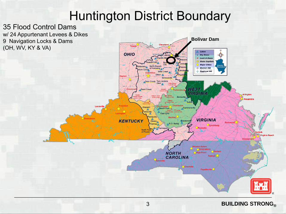
35 Flood Control Damsw/ 24 Appurtenant Levees & Dikes 9 Navigation Locks & Dams(OH, WV, KY & VA)
Bolivar Dam
Huntington District Boundary

US Army Corps of EngineersBUILDING STRONG® http://www.dnr.state.oh.us/
portals/10/pdf/glacial.pdf
Glacial Geology
Illinoian Ice Margin
Wisconsin Ice Margin
US Army Corps of EngineersBUILDING STRONG®
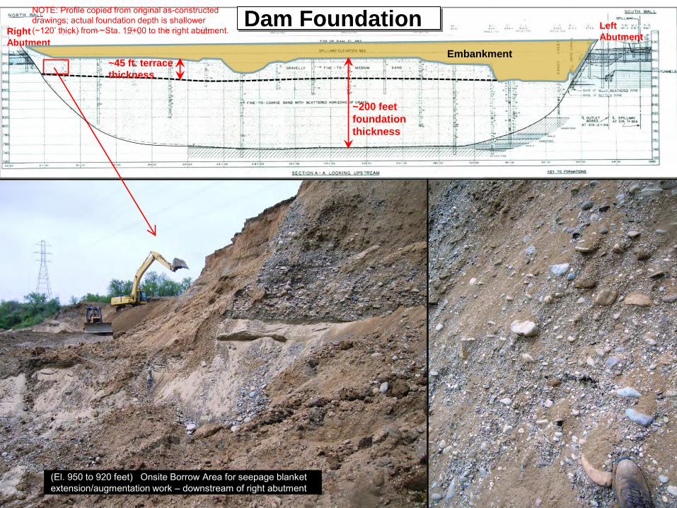
(El. 950 to 920 feet) Onsite Borrow Area for seepage blanket extension/augmentation work – downstream of right abutment
Left AbutmentRight
Abutment
Dam FoundationEmbankment
~200 feetfoundation thickness
~45 ft. terrace thickness
NOTE: Profile copied from original as-constructed drawings; actual foundation depth is shallower (~120’ thick) from ~Sta. 19+00 to the right abutment.
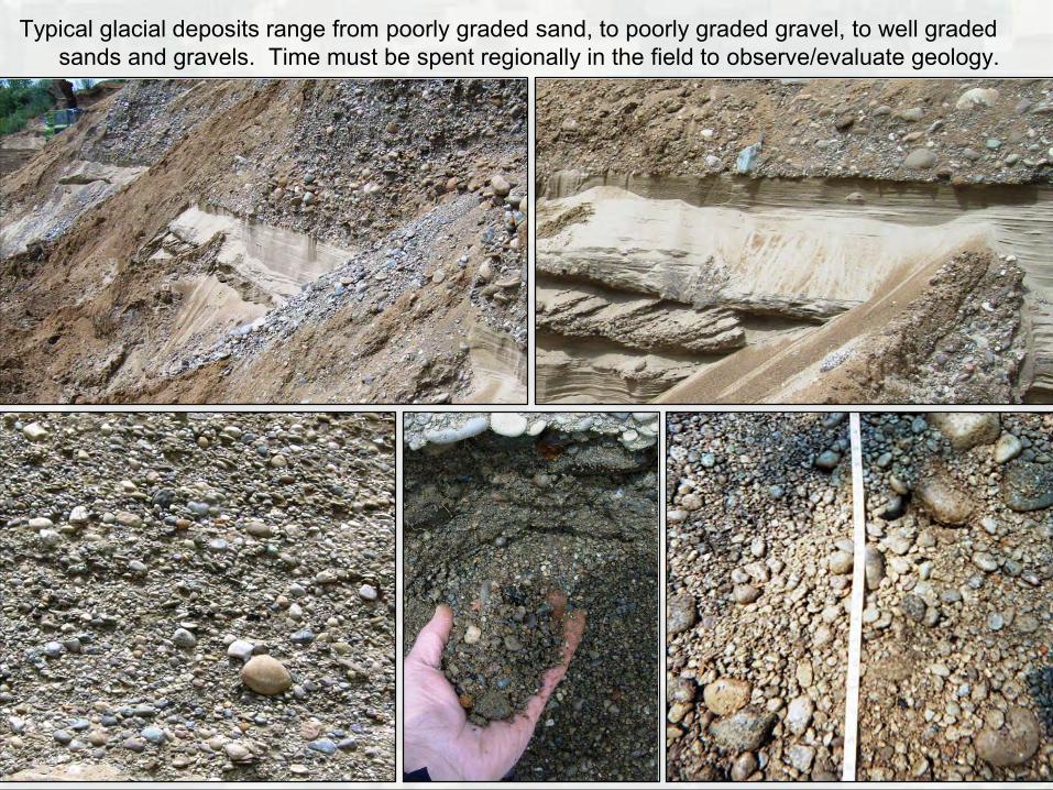
Typical glacial deposits range from poorly graded sand, to poorly graded gravel, to well graded sands and gravels. Time must be spent regionally in the field to observe/evaluate geology.
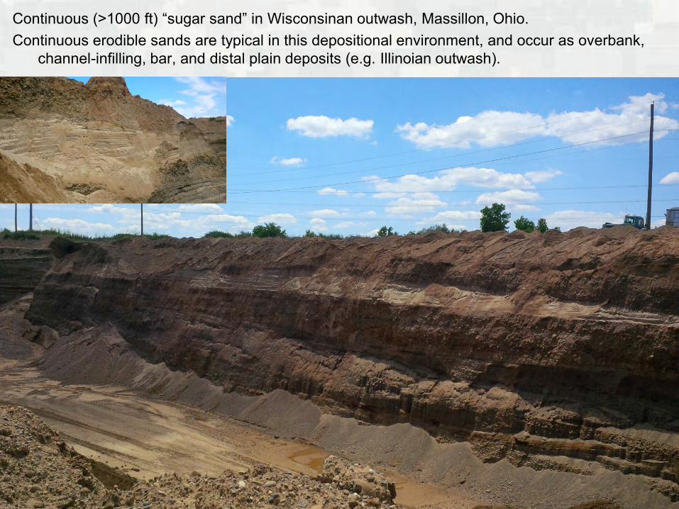
Continuous (>1000 ft) “sugar sand” in Wisconsinan outwash, Massillon, Ohio.Continuous erodible sands are typical in this depositional environment, and occur as overbank,
channel-infilling, bar, and distal plain deposits (e.g. Illinoian outwash).

US Army Corps of EngineersBUILDING STRONG® 8
Glacial Outwash: Sand & Gravel
Bolivar Dam – Typical Cross Section
NORMAL - 910
UNUSUAL - 964
EXTREME (PMF) – 982.5Upstream Downstream
IMFCP 949
US Army Corps of EngineersBUILDING STRONG®
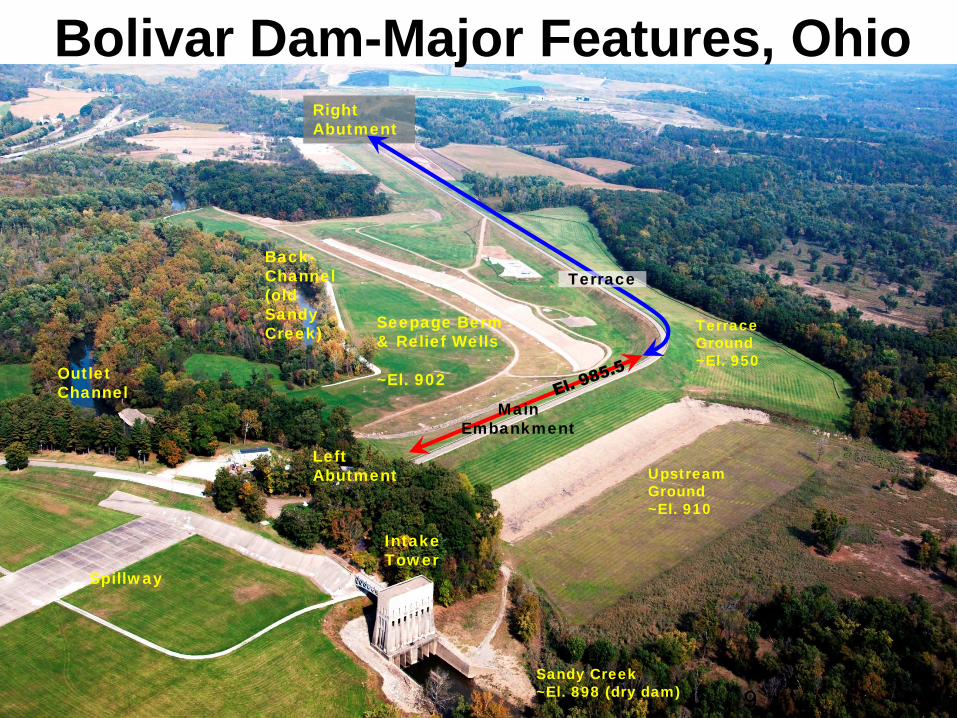
Bolivar Dam-Major Features, Ohio
9
Left Abutment
Right Abutment
Terrace
Main Embankment
Spillway
Intake Tower
Outlet Channel
Back-Channel(old SandyCreek)
Seepage Berm & Relief Wells
~El. 902
Upstream Ground~El. 910
Terrace Ground~El. 950
Sandy Creek~El. 898 (dry dam)
BUILDING STRONG®
Dam Performance
10
BUILDING STRONG®
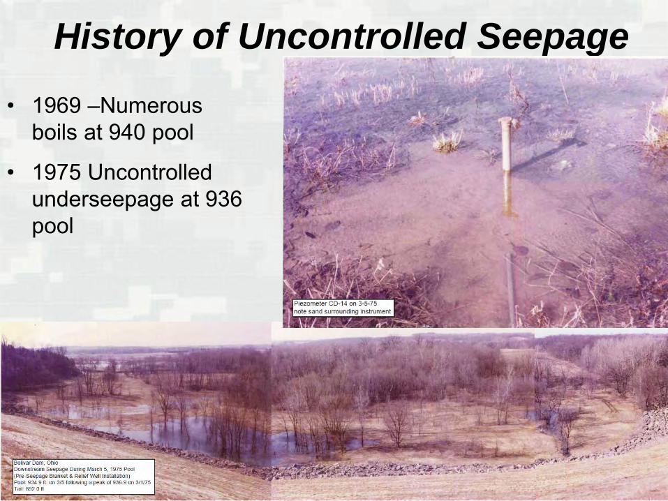
• 1969 –Numerous boils at 940 pool
• 1975 Uncontrolled underseepage at 936 pool
History of Uncontrolled Seepage
BUILDING STRONG®
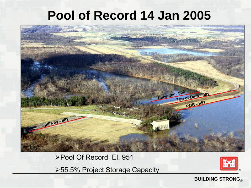
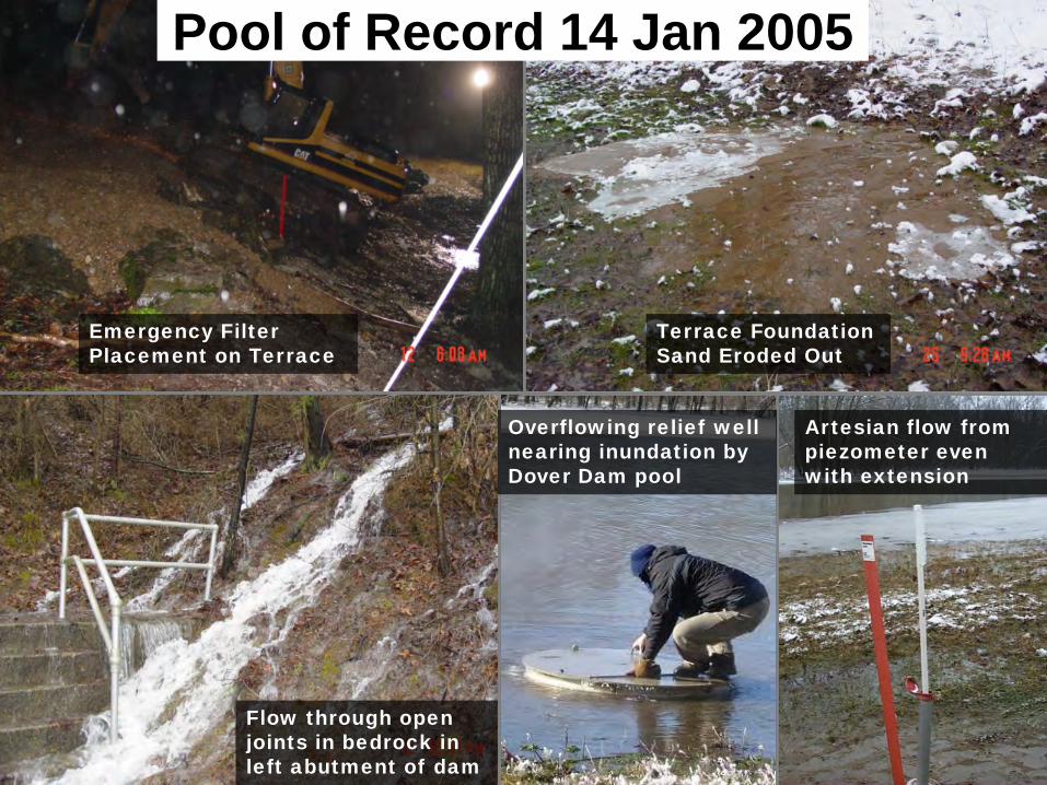
Pool of Record 14 Jan 2005
Pool Of Record El. 951
55.5% Project Storage Capacity
BUILDING STRONG®
Terrace Foundation Sand Eroded Out
Emergency Filter Placement on Terrace
Overflowing relief well nearing inundation by Dover Dam pool
Artesian flow from piezometer even with extension
Flow through open joints in bedrock in left abutment of dam
Pool of Record 14 Jan 2005

BUILDING STRONG®
Mar 2008 – El. 936
2008 & 2011 High Water Events
March 2011 (pool 946’, tail 901’) photo with max PZ readings indicated. A lot of seepage also discharging through 2’ collector/gravel drain and into 6’ sand berm; seepage quantity significantly greater than that visible in photo.
PZ D-67, STA 50+70TOG: 926.4’, Tip: 914.2’Max PZ 03/11: 920.5Max PZ 01/05: 924.4’PMF (linear) ~ 945-957’

BUILDING STRONG®15
Major Rehablitaion
BUILDING STRONG®
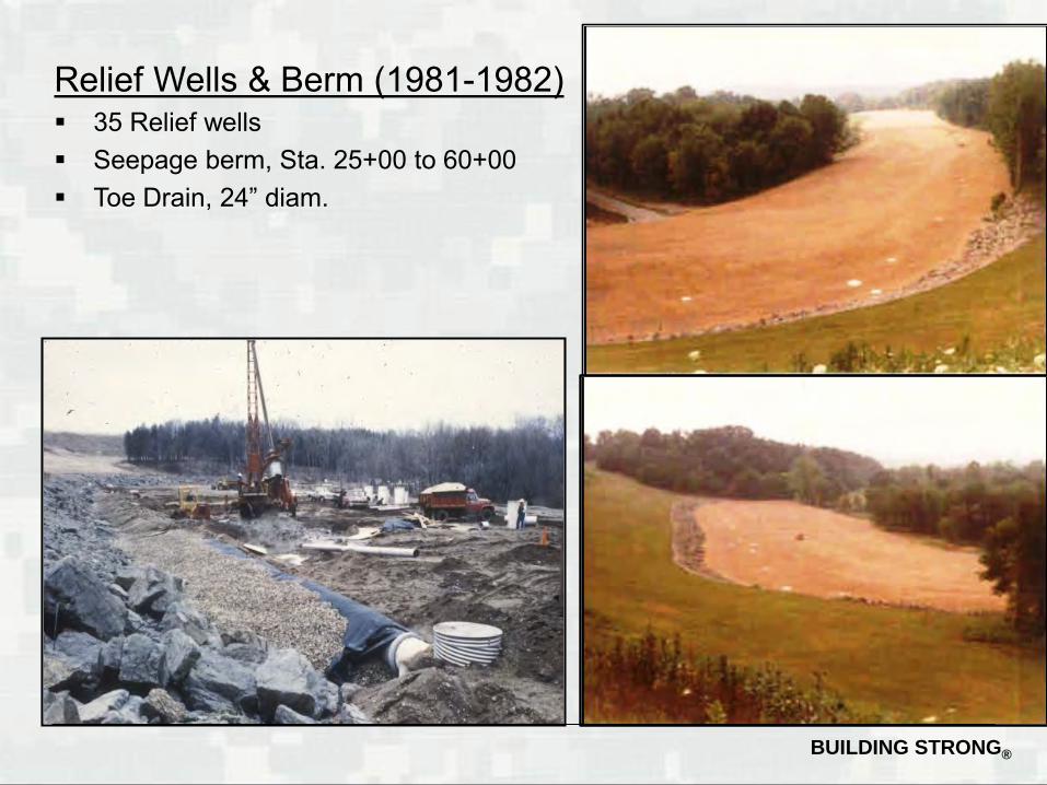
Relief Wells & Berm (1981-1982) 35 Relief wells Seepage berm, Sta. 25+00 to 60+00 Toe Drain, 24” diam.

BUILDING STRONG®
Spillway Widening & Parapet Wall Construction (1989)A. 3.5 ft. Parapet Wall on upstream
crest.B. Upstream stability bermC. Spillway widened to 540 ft.
270 ft
540 ft
A
B
C

BUILDING STRONG®
SANDY CREEK
Major Rehabilitation(post Pool of Record)
1) Terrace slope filter (2009)2) Rehab. wells (prelim.) (2009)3) Downstream filter berm extension (2012)4) ADAS Ph. 1 & 2 (2013-14)5) Seepage barrier & abut. grout curtain (2016)6) ADAS Ph. 3 (2016-17)
BUILDING STRONG®
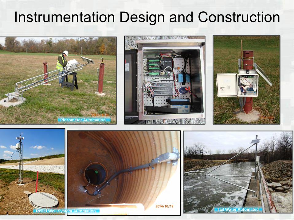
Instrumentation Design and Construction
19 Tail Water AutomatedRelief Well System Automation
Piezometer Automation

BUILDING STRONG®
Pool: 982 ft
Tailwater: 930 ft
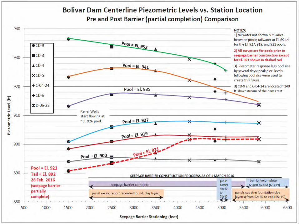
Seepage Barrier Design
Pre Seepage Barrier
Post Seepage Barrier
BUILDING STRONG®
Seepage Barrier Construction
21
BUILDING STRONG®
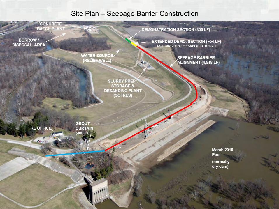
Site Plan – Seepage Barrier Construction
March 2016 Pool
(normally dry dam)
BUILDING STRONG®
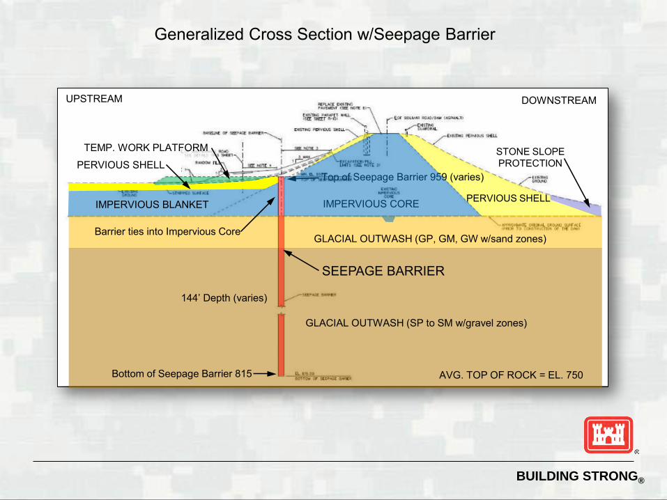
Generalized Cross Section w/Seepage Barrier
UPSTREAM DOWNSTREAM
IMPERVIOUS CORE PERVIOUS SHELL
PERVIOUS SHELLTEMP. WORK PLATFORM
Top of Seepage Barrier 959 (varies)
STONE SLOPE PROTECTION
IMPERVIOUS BLANKET
Barrier ties into Impervious Core
SEEPAGE BARRIER
GLACIAL OUTWASH (SP to SM w/gravel zones)
144’ Depth (varies)
Bottom of Seepage Barrier 815
GLACIAL OUTWASH (GP, GM, GW w/sand zones)
AVG. TOP OF ROCK = EL. 750
BUILDING STRONG®
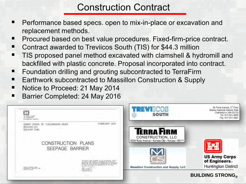
Construction Contract Performance based specs. open to mix-in-place or excavation and
replacement methods. Procured based on best value procedures. Fixed-firm-price contract. Contract awarded to Treviicos South (TIS) for $44.3 million TIS proposed panel method excavated with clamshell & hydromill and
backfilled with plastic concrete. Proposal incorporated into contract. Foundation drilling and grouting subcontracted to TerraFirm Earthwork subcontracted to Massillon Construction & Supply Notice to Proceed: 21 May 2014 Barrier Completed: 24 May 2016
BUILDING STRONG®
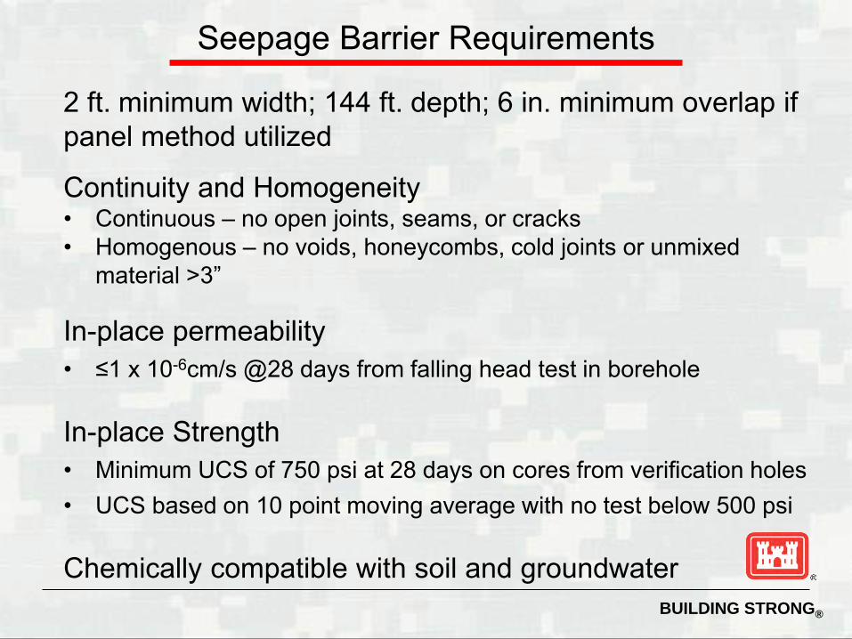
2 ft. minimum width; 144 ft. depth; 6 in. minimum overlap if panel method utilized
Continuity and Homogeneity• Continuous – no open joints, seams, or cracks• Homogenous – no voids, honeycombs, cold joints or unmixed
material >3”
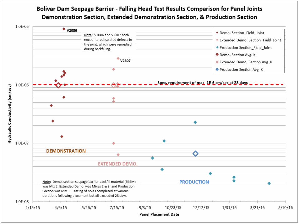
In-place permeability• ≤1 x 10⁻⁶cm/s @28 days from falling head test in borehole
In-place Strength• Minimum UCS of 750 psi at 28 days on cores from verification holes• UCS based on 10 point moving average with no test below 500 psi
Chemically compatible with soil and groundwater
Seepage Barrier Requirements
BUILDING STRONG®
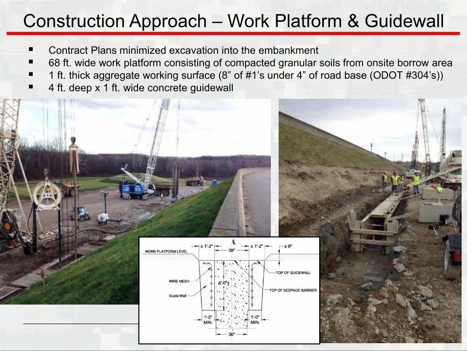
Construction Approach – Work Platform & Guidewall Contract Plans minimized excavation into the embankment 68 ft. wide work platform consisting of compacted granular soils from onsite borrow area 1 ft. thick aggregate working surface (8” of #1’s under 4” of road base (ODOT #304’s)) 4 ft. deep x 1 ft. wide concrete guidewall
BUILDING STRONG®
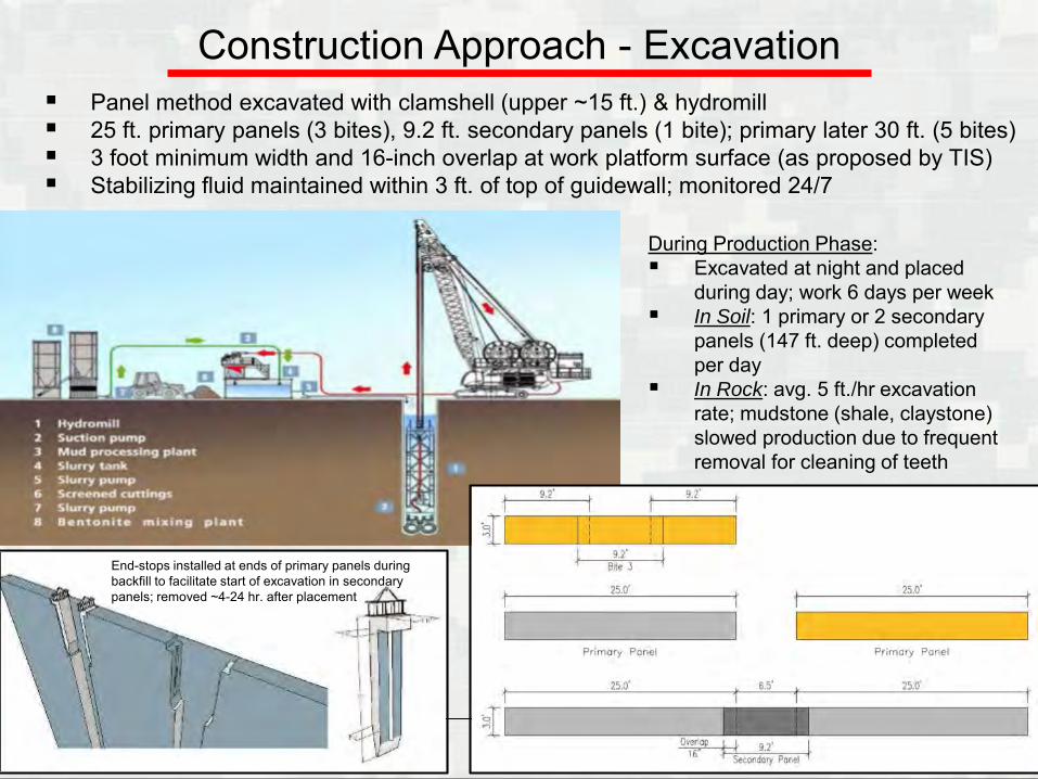
Construction Approach - Excavation Panel method excavated with clamshell (upper ~15 ft.) & hydromill 25 ft. primary panels (3 bites), 9.2 ft. secondary panels (1 bite); primary later 30 ft. (5 bites) 3 foot minimum width and 16-inch overlap at work platform surface (as proposed by TIS) Stabilizing fluid maintained within 3 ft. of top of guidewall; monitored 24/7
During Production Phase: Excavated at night and placed
during day; work 6 days per week In Soil: 1 primary or 2 secondary
panels (147 ft. deep) completed per day
In Rock: avg. 5 ft./hr excavation rate; mudstone (shale, claystone) slowed production due to frequent removal for cleaning of teeth
End-stops installed at ends of primary panels during backfill to facilitate start of excavation in secondary panels; removed ~4-24 hr. after placement
BUILDING STRONG®
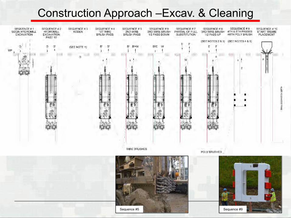
Construction Approach –Excav. & Cleaning
Sequence #5 Sequence #9
BUILDING STRONG®
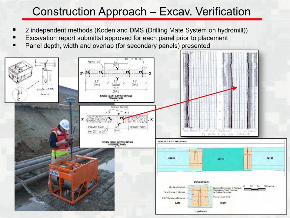
Construction Approach – Excav. Verification 2 independent methods (Koden and DMS (Drilling Mate System on hydromill)) Excavation report submittal approved for each panel prior to placement Panel depth, width and overlap (for secondary panels) presented
BUILDING STRONG®
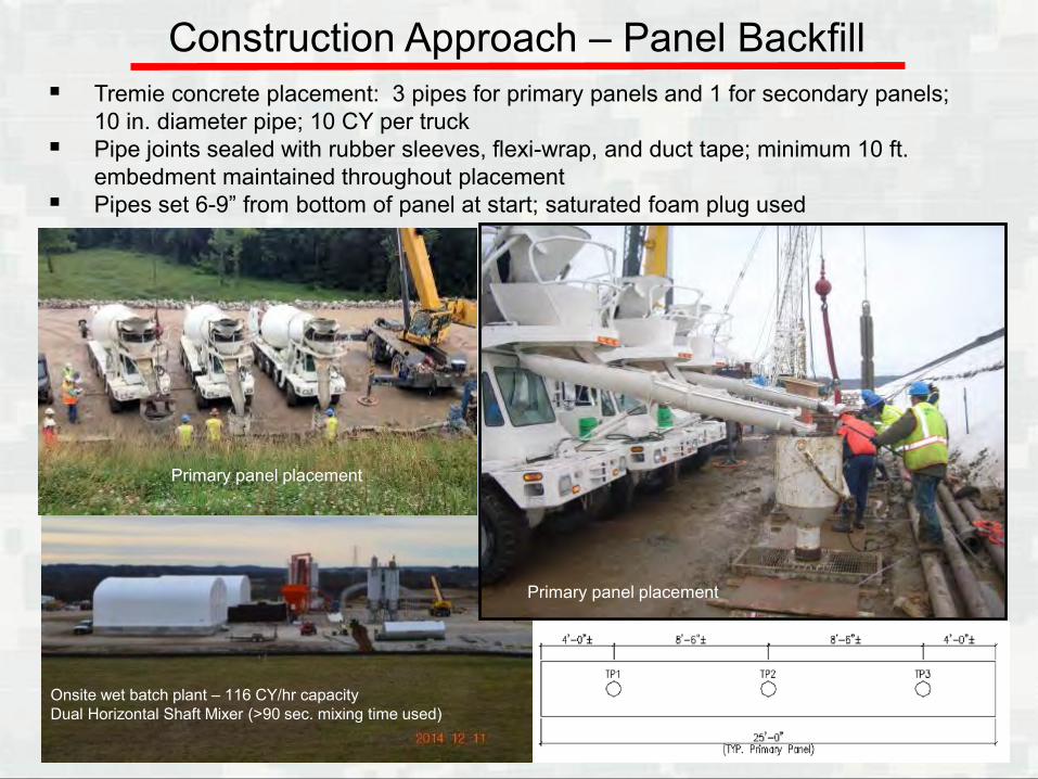
Construction Approach – Panel Backfill Tremie concrete placement: 3 pipes for primary panels and 1 for secondary panels;
10 in. diameter pipe; 10 CY per truck Pipe joints sealed with rubber sleeves, flexi-wrap, and duct tape; minimum 10 ft.
embedment maintained throughout placement Pipes set 6-9” from bottom of panel at start; saturated foam plug used
Onsite wet batch plant – 116 CY/hr capacityDual Horizontal Shaft Mixer (>90 sec. mixing time used)
Primary panel placement
Primary panel placement
BUILDING STRONG®
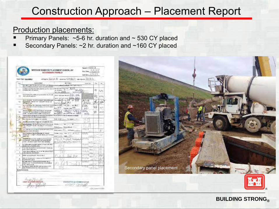
Construction Approach – Placement ReportProduction placements: Primary Panels: ~5-6 hr. duration and ~ 530 CY placed Secondary Panels: ~2 hr. duration and ~160 CY placed
Secondary panel placement
BUILDING STRONG®
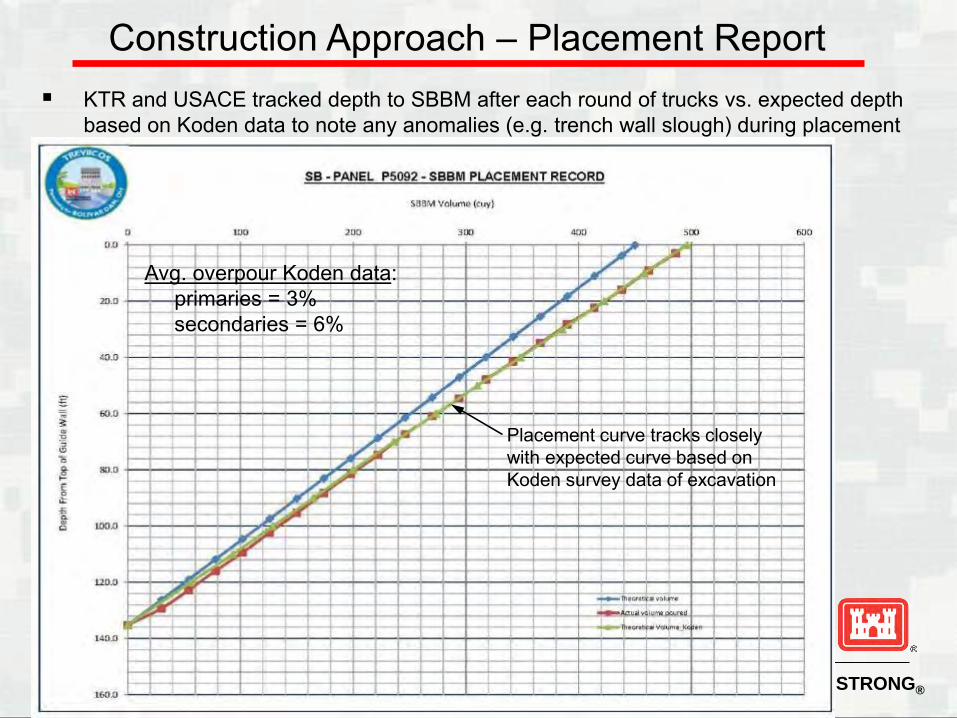
Construction Approach – Placement Report KTR and USACE tracked depth to SBBM after each round of trucks vs. expected depth
based on Koden data to note any anomalies (e.g. trench wall slough) during placement
Placement curve tracks closely with expected curve based on Koden survey data of excavation
Avg. overpour Koden data:primaries = 3%secondaries = 6%

BUILDING STRONG®
Seepage Barrier Backfill Material (SBBM)
Plastic Concrete constituents:
• Type I Portland Cement
• Grade 100 Ground Granulated Blast Furnace Slag
• Bentonite – BaraKade SP WY sodium
• Water – on-site relief well
• Natural Sand – local quarry
• AASHTO #8 Natural Stone – local quarry
• Admixtures - Lamsperse HS - dispersant for bentonite-cement
slurries- Grace Recover - hydration inhibitor
NOTE: KTR mix design (Raffaella Granata, TREVI)
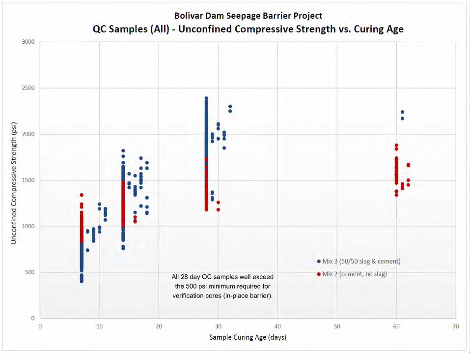
Quality Control Checks• Slump• Temperature• Air Content• UCS• Permeability• Aggregate moisture
& gradation
QA check of slump during secondary panel placement
BUILDING STRONG®
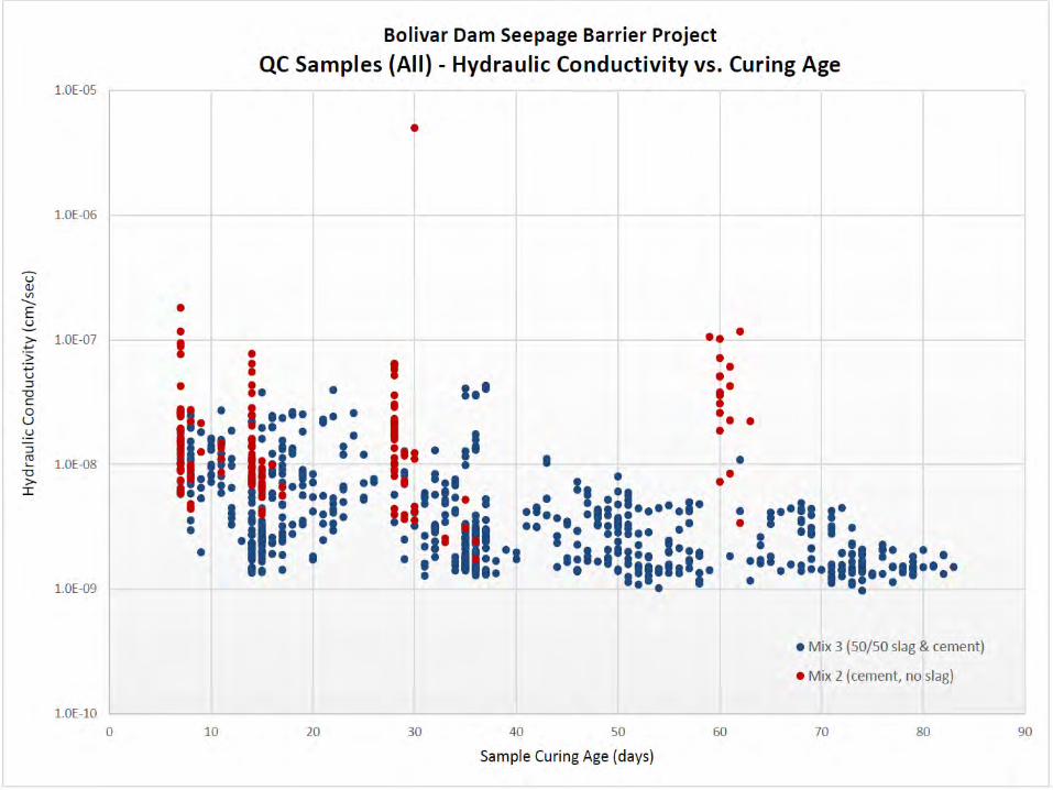
All 28 day QC samples well exceedthe 500 psi minimum required for
verification cores (in-place barrier).
BUILDING STRONG®
BUILDING STRONG®
Seepage Barrier Verification
36
BUILDING STRONG®
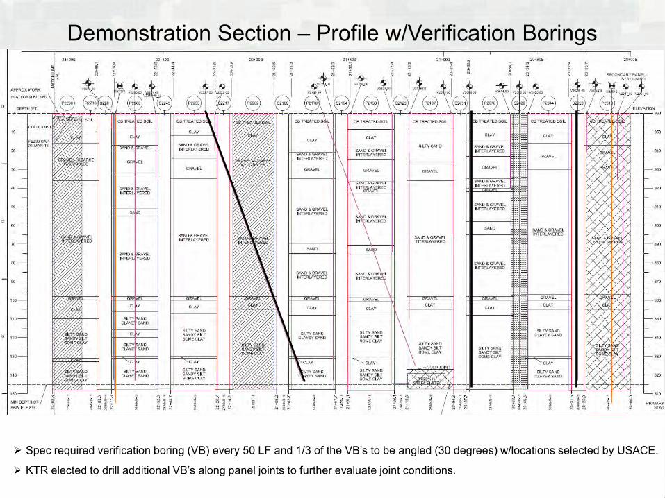
Demonstration Section – Profile w/Verification Borings
Spec required verification boring (VB) every 50 LF and 1/3 of the VB’s to be angled (30 degrees) w/locations selected by USACE.
KTR elected to drill additional VB’s along panel joints to further evaluate joint conditions.
BUILDING STRONG®
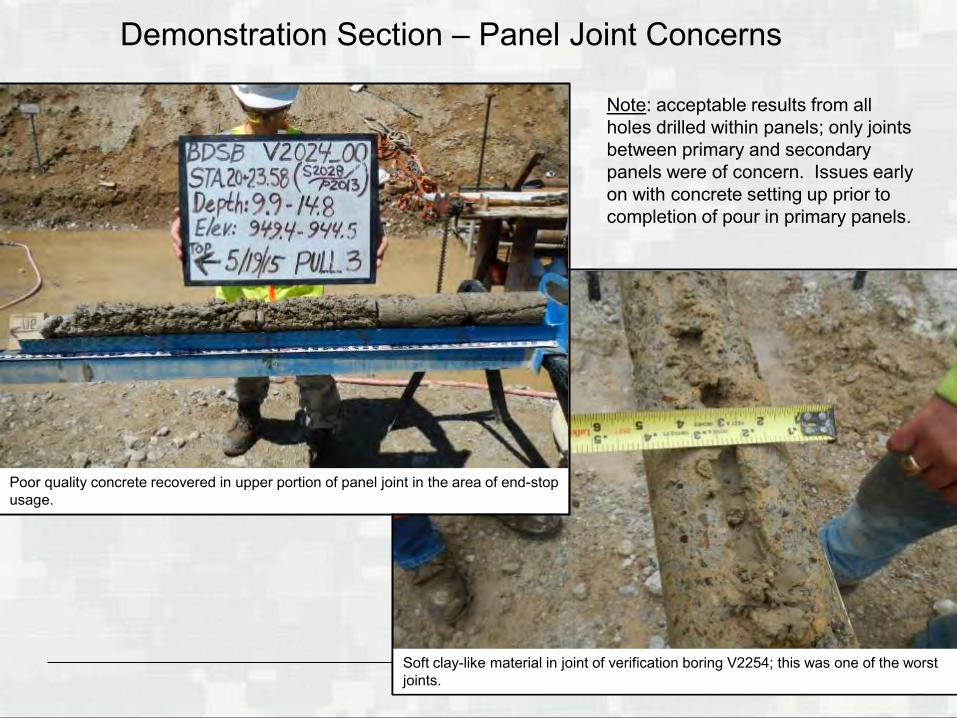
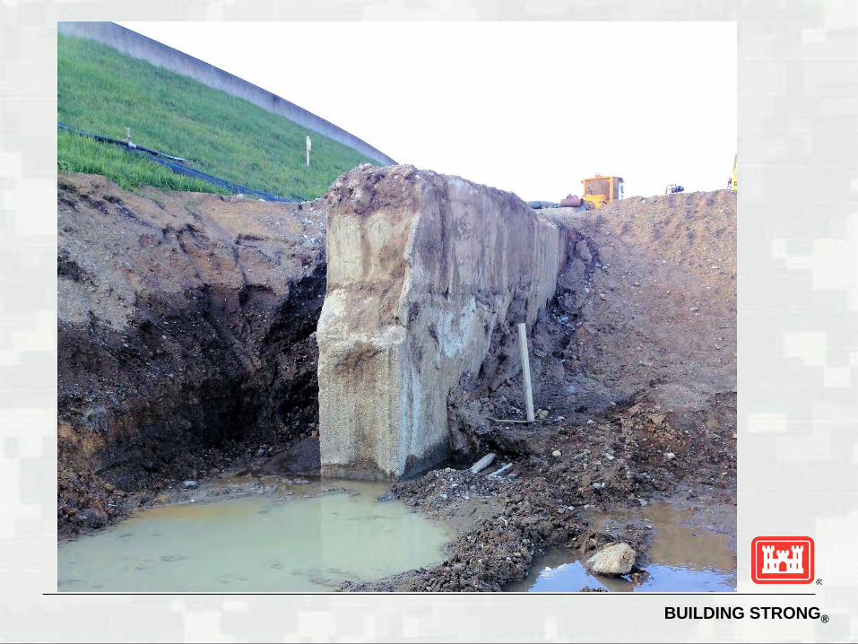
Demonstration Section – Panel Joint Concerns
Poor quality concrete recovered in upper portion of panel joint in the area of end-stop usage.
Soft clay-like material in joint of verification boring V2254; this was one of the worst joints.
Note: acceptable results from all holes drilled within panels; only joints between primary and secondary panels were of concern. Issues early on with concrete setting up prior to completion of pour in primary panels.
BUILDING STRONG®
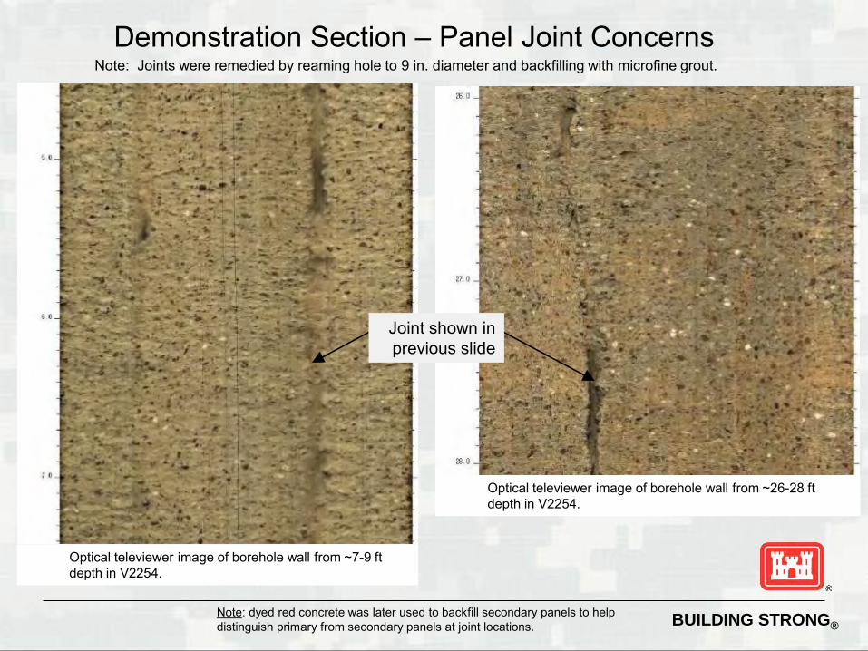
Demonstration Section – Panel Joint Concerns
Optical televiewer image of borehole wall from ~7-9 ftdepth in V2254.
Optical televiewer image of borehole wall from ~26-28 ftdepth in V2254.
Note: dyed red concrete was later used to backfill secondary panels to help distinguish primary from secondary panels at joint locations.
Joint shown in previous slide
Note: Joints were remedied by reaming hole to 9 in. diameter and backfilling with microfine grout.
BUILDING STRONG®
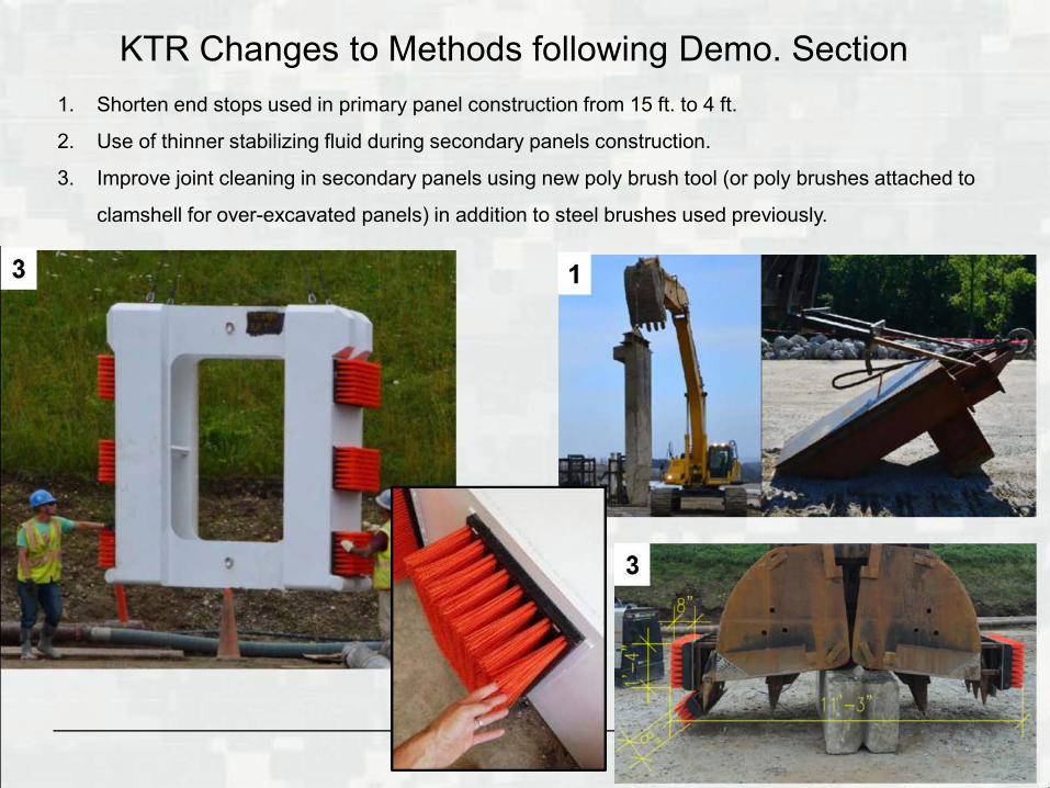
KTR Changes to Methods following Demo. Section1. Shorten end stops used in primary panel construction from 15 ft. to 4 ft.
2. Use of thinner stabilizing fluid during secondary panels construction.
3. Improve joint cleaning in secondary panels using new poly brush tool (or poly brushes attached to
clamshell for over-excavated panels) in addition to steel brushes used previously.
BUILDING STRONG®
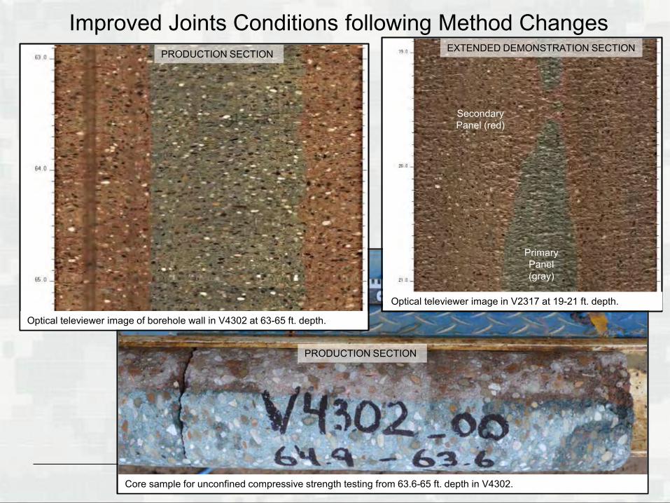
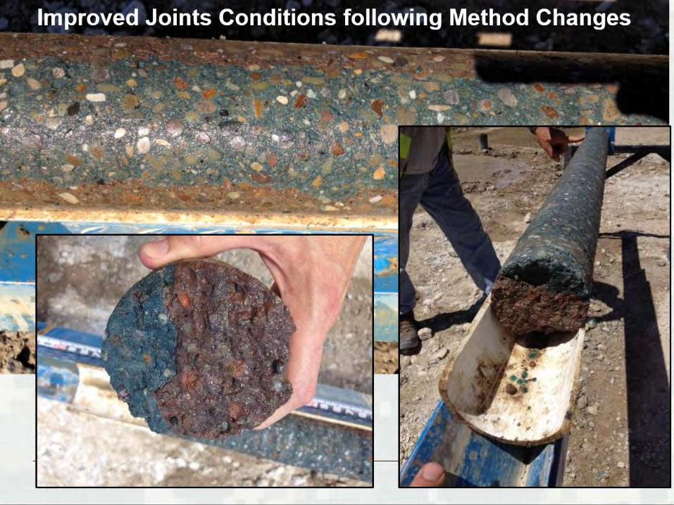
Improved Joints Conditions following Method Changes
Optical televiewer image of borehole wall in V4302 at 63-65 ft. depth.
Core sample for unconfined compressive strength testing from 63.6-65 ft. depth in V4302.
Optical televiewer image in V2317 at 19-21 ft. depth.
EXTENDED DEMONSTRATION SECTIONPRODUCTION SECTION
PRODUCTION SECTION
Primary Panel (gray)
Secondary Panel (red)
BUILDING STRONG®
BUILDING STRONG®
BUILDING STRONG®

BUILDING STRONG®

BUILDING STRONG®
Seepage Barrier Performance Monitoring
46
BUILDING STRONG®
BUILDING STRONG®
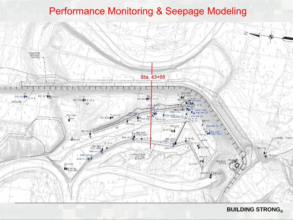
Performance Monitoring & Seepage Modeling

BUILDING STRONG®
BUILDING STRONG®
Questions
50