siso piezo based circuit development for active structural
TRANSCRIPT

Fluids 2020, 5, 183; doi:10.3390/fluids5040183 www.mdpi.com/journal/fluids
Article
SISO Piezo Based Circuit Development for Active
Structural Vibration Control
Maurizio Arena * and Massimo Viscardi
Department of Industrial Engineering, Aerospace Section, University of Naples “Federico II”, Via Claudio 21,
80125 Naples, Italy; [email protected]
* Correspondence: [email protected]
Received: 3 September 2020; Accepted: 14 October 2020; Published: 16 October 2020
Abstract: This paper deals with the issue of developing a smart vibration control platform following
an innovative model‐based approach. As a matter of fact, obtaining accurate information on system
response in pre‐design and design phases may reduce both computational and experimental efforts.
From this perspective, a multi‐degree‐of‐freedom (MDOF) electro‐mechanical coupled system has
been numerically schematized implementing a finite element formulation: a robust simulation tool
integrating finite element model (FEM) features with Simulink® capabilities has been developed.
Piezo strain actuation has been modelled with a 2D finite element description: the effects exerted on
the structure (converse effect) have been applied as lumped loads at the piezo nodes interface. The
sensing (direct effect) has instead been modelled with a 2D piezoelectric constitutive equation and
experimentally validated as well. The theoretical study led to the practical development of an
integrated circuit which allowed for assessing the vibration control performance. The analysis of
critical parameters, description of integrated numerical models, and a discussion of experimental
results are addressed step by step to get a global overview of the engineering process. The single
mode control has been experimentally validated for a simple benchmark like an aluminum
cantilevered beam. The piezo sensor‐actuator collocated couple has been placed according to an
optimization process based on the maximum stored electrical energy. Finally, a good level of
correlation has been observed between the forecasting model and the experimental application: the
frequency analysis allowed for characterizing the piezo couple behavior even far from the resonance
peak.
Keywords: active control; piezo‐based circuits; reduced numerical models
1. Outlook
An innovative vibro‐acoustic active control system for engineering transportation application
has been numerically conceptualized and then validated by experimental evidence. This paper
addresses the vibration control of elastic structures using piezoelectric transducers as a collocated
sensor‐actuator pair. The encouraging results achieved in basic test cases can be extended to more
complex structures when excited by external sources, i.e., flow turbulence, tonal loads, engines, etc.
2. Introduction
2.1. Literature Background
The optimization of structural vibrations still represents a real engineering challenge in various
fields of application. Modern techniques are based on scientific concepts developed 30 years ago
which are accompanied by technological spreads in order to develop increasingly performing
devices. Conducting materials, metamaterials, integrated electronic circuits, and so on represent the

Fluids 2020, 5, 183 2 of 20
current means that allow for the achievement of these research goals. The passive control technique
widely used in the applications of means of transport and industrial machines is certainly among the
most commonly adopted: they do not require external power systems and their operation is simply
based on mechanical coupling with the host structure. As a result of advances in the electronics and
materials field, a growing interest has arisen in the implementation of active or semi‐active control
systems: many studies have shown their real feasibility even with complex applications. The low cost
of the actuators, often made of PZT (lead zirconate titanate) material, and the simple implementation
in control circuits are certainly among the motivating factors in their use. Studies on the performance
of piezoelectric materials as known are not so recent: their applications have been shown to be a
viable concept for vibration reduction in many fields. Crawley and de Luis [1] proposed an analytical
approach for a static case including several actuator geometries to be bonded on flexible substrates.
A dynamic modeling technique for the vibration suppression of plate structures by using piezo
patches is detailed in [2]. The first real applications in aerospace structures were made by [3,4]. Both
numerical and test results showed the potentiality of such technology for controlling noise radiated
by panels [5,6]. The performance evaluation, in terms of vibration and noise attenuation, of a framed
panel comprising a single‐input‐single‐output (SISO) control technique was discussed. In particular,
a simple analogic control system that implements a positive position feedback control law with self‐
adaptive gain has been proposed and widely tested. From this perspective, a “collocated” SISO
control system, where the sensor and the actuator are placed at the same location, can be a very
advantageous solution: it does not require any particular signal elaboration (displacement or velocity
feedback, easily achieved by hardware). Due to the piezoelectric effect, a percentage of the vibrational
mechanical energy can be converted into electric energy and dissipated suitably by means of a shunt
circuit that compounds a mechanism of passive damping. The shunt represents a special application
of SISO‐based control. Shunt circuits are mainly used to condition voltage signals, which, thanks to
the piezoelectric properties, are representative of the dynamic deformation energy of the structure.
Lesieutre discusses the four commonly used types of shunt circuits: resistive, resonant, capacitive,
and switched [7]. Richard et al. [8] investigated the technique based on a synchronized switch for
broadband vibration damping. An inductive element was used for inverting the voltage signal on a
piezo transducer so as to counteract the external disturbance action. Guyomar et al. [9] addressed the
study of a new technique, namely synchronized switch harvesting (SSH), for electrical energy
generation by the structural vibration provided by piezoelectric actuators patches. CIRA (Italian
Research Aerospace Centre) engaged a considerable interest in the development of control
methodologies based on the aid of shunt circuits [10–13]. An energetic approach comprising both
theoretical and simulation studies addressed the design of a first switching shunt control (SSC)
architecture for the vibration control of a beam structure, [10]. An integrated design scheme for a SSC
circuit, suitably combining properties from multi‐degree‐of‐freedom (MDOF) structural FE models
has been analysed in [11]. An in‐house simulation code is described in [12] which, by implementing
the Newmark–Beta integration method, solved in the time domain the coupled equations of
dynamics (with and without control effect) with particular reference to beam systems. The study was
also extended to 2D composite plates using a multi‐channel system capable of controlling several
pairs of piezoelectric actuator/sensor working independently as SISO systems, [13]. Attention was
also paid to the conception of the individual electronic components in order to improve the
performance of the control boards. Numerical and experimental studies have led to the design of a
synthetic inductor also useful for multi‐modal applications, [14], as well as the possibility of
optimizing the number of components used in order to streamline the circuit assembly complexity,
[15]. The effect of changing positions of piezo patches along the analyzed structure are discussed in
[16]. The piezoelectric transducer shunted with a RL couple [17], or the electromagnetic transducer
shunted with a RC couple [18] are the two‐order circuit that can generate an electrical resonance. The
work [19] provides the description of a first experimental circuit for the vibration control of a flat
aluminium plate by a resonant piezoelectric shunt in a water environment. The main electrical
components of the resonant shunt, i.e., inductance and resistor, have been designed relying on the
resonance frequencies in open loop and closed loop conditions. Parametric FEM computations and

Fluids 2020, 5, 183 3 of 20
periodical structure theory for geometric and electric parameter optimizations of a piezo control
circuit have been carried out in [20]. This work provides an efficient but also general formulation for
the prediction of dynamic behaviour of all kinds of elastic slender structures with shunted piezo
patches. A novel concept of a nonlinear piezoelectric tuned vibration absorber (NPTVA) is introduced
by the authors of [21]. They propose the design of a fully passive nonlinear inductor using the
principle of magnetic saturation. The control performance with single or multiple inductors has been
verified considering a beam with piezoelectric patches. The literary bibliography dealing with active
and passive control methodologies is huge: some recent reviews have amply discussed the
developments, especially regarding the applications of shunt piezoelectric systems. Yan et al. [22]
summarize the control principles, including descriptive equations and circuit diagrams, while also
pressing on the current challenges and prospects of this technology in vibration and noise control.
Marakakis et al. [23] point out the optimization criteria of such systems by operating both on the
design and positioning of the piezoelectric devices and on the enhancement of the system
characteristics.
2.2. Research Objective
The authors of present paper already carried out experimental activities on the semi‐active
vibration control with reference to simple isotropic structures by using “collocated” piezo devices,
[24]. The current study deals with the development of an integrated circuit for the vibration control
implementation. A full in‐house finite element procedure, according to a local equation describing
the fully coupled system, has been implemented in a Simulink® environment to assess the operating
principle of a SISO shunted control law. Piezo strain actuation and sensing have been modelled with
a well‐established analytic approach using the “direct” and “inverse” effect. The authors propose a
resolution method based on the state‐space transformation which can lead to a considerable
reduction of the computational cost with respect to other integration techniques. The authors would
like to propose a design methodology that can be easily extended to structures even more complex
than the one analysed: the first order model developed now in Simulink® can work in real‐time by
extracting the characteristic matrices from any finite element solver solving the dynamic problem in
spectral domain. The equations of structural mechanics are solved separately without considering
the piezoelectric contribution. The electro‐mechanical action of the piezoelectric is implemented only
downstream and only at the nodes of interest. Relying upon the basic theoretical considerations, the
authors therefore addressed some key insights for the development of an innovative hardware
control platform. The study addressed the design of a novel circuit, based on a pulse train generator
and solid‐state devices: this has been realised to implement the synchronized SISO control. In this
paper, an electronic board implementing complementary metal‐oxide semiconductor (CMOS) pulse
shaper has been proposed for the shunt switching purpose. CMOS operational amplifier is suitable
for technology applications requiring low broadband noise and low supply current as well. Literature
reference for this kind of integrated component, [25]. The overall system incorporates a MOS
transistors bridge, an integrator, one small capacitor, and one resistor. At this point, the semi‐active
control is based on the impulsive excitation of a supplementary resonant RLC‐series circuit suitable
to control the synchronized charge of the piezoelectric actuator. In perspective of optimizing the
dynamic performance of the circuit, an innovative feedback technique has been investigated by
modulating the signal of resistor of the RLC control circuit unlike many applications where it is taken
across the capacitance. The actual effectiveness was experienced using a real prototype. The control
board operation was checked before without applying the signal amplifier: the performance of the
piezo actuator alone has come to a reduction of up to 3 dB. By increasing the gain to 95% of amplifier
power, the reduction reaches 12 dB, in line with numerical expectations. The board followed the
design criteria for meeting the demands of low‐power, small‐size, and high‐performance
requirements. The development of a cheap and low weight electronic platform is the added value of
the work. From such a perspective, there are not many bibliographical references on the application
of such novel components for micro electro‐mechanical systems (MEMS) application.

Fluids 2020, 5, 183 4 of 20
3. Physical Principle Overview
3.1. State‐Space Representation of Structural Model
Modelling of a structure with attached piezoelectric actuators using FE approach can be
performed like any conventional numerical formulation. Actually, the structural characteristics in the
form of known matrices; mass and stiffness, have been extracted as DMIG (direct matrix input at a
grid) from MSC Nastran® (MSC Software, Newport Beach, CA, USA) analysis. In dynamic analysis,
the main properties (i.e., mass, damping, and stiffness) may be provided, in part or entirely, as
properties of FEM grid points through the use of these direct input matrices. Mathematical
representation through structured matrices is the basis of reduction Guyan technique. This method
allows for reducing huge number of degrees of freedom of dynamic models minimizing the loss of
accuracy in the representation of inertial and elasticity distributions. The DMIG card accommodates
entries by components of geometric grid points, scalar points, or extra points introduced for dynamic
analysis. The proportional damping assumption (Basile model) has been implemented to transcribe
the matrix of modal damping coefficients. In such a way, the matrices have been used to express the
dynamic equilibrium of the excited system in the state‐space domain. A first procedure for modelling
structures containing piezoelectric actuators using MSC Nastran® and Matlab® was already
developed by the NASA Research Center [26]. The paper describes the utility and functionality of
one set of validated modelling tools. The innovative aspect of this approach is to separate the state
space equation for structure’s behaviour description, from the piezo numerical model, despite
solving the coupled problem. The simplicity of this approach ensures smaller and flexible codes, that
can be adapted to different mock‐up experiments reducing the computational complexity. It is
possible solving a system of 6N‐C differential equations, where N is the nodes’ number in which the
structure has been discretized and C is the number of kinematic constraint in accordance with finite
element (FE) model analysed. Considering that each node has 6 DOFs, 3 translational and 3 rotational,
it is possible to reduce the number of equations just considering the most relevant displacement
directions. This system can be written in compact form using the FE matrixes as follows Equation (1):
𝑀 𝑧 𝑡 𝐷 𝑧 𝑡 𝐾 𝑧 𝑡 𝐹 𝑡 (1)
The relation Equation (1) represents the dynamic equilibrium for a linear non‐conservative (with
damping) system in the presence of time applied load F(t). It is univocally described by a finite set of
physical coordinates. Globally, the system comprises n linear differential equations of the second
order with constant coefficients. [M], [D], and [K] represent, respectively, the mass, damping, and
stiffness matrix. The second degree ODE (ordinary differential equation) system could be reduced in
the state‐space domain: this arrangement allowed for solving just a first order system. The following
feedback formulation was developed in [27] for a passive absorber problem and in [28] for
piezoceramic actuators. Considering a new variable basis ηi, the physical coordinates representing
the nodal displacement and velocity can be reported as Equations (2) and (3):
𝜂 𝑡 𝑧 𝑡 (2)
𝜂 𝑡 𝑧 𝑡 (3)
The formulation of dynamic equilibrium in state‐space domain is therefore given by Equations
(4)–(6). The matrix M is by definition square and with a non‐zero determinant so it can be inverted
as indicated in Equation (4).
𝜂 𝑡 𝜂 𝑡𝜂 𝑡 𝑀 𝐾 𝜂 𝑡 𝑀 𝐷 𝜂 𝑡 𝑀 𝐹 𝑡
(4)
𝜂 𝑡𝜂 𝑡
𝑂 𝐼
𝑀 𝐾 𝑀 𝐷 𝜂 𝑡𝜂 𝑡
𝑂𝑀
𝐹 𝑡 (5)
𝜂 𝑡 𝐴 𝜂 𝑡 𝐵 𝐹 𝑡 (6)

Fluids 2020, 5, 183 5 of 20
where [A] is the state matrix Equation (7), [B] the input array Equation (8), and {F} the external
disturbance.
𝐴 𝑂 𝐼
𝑀 𝐾 𝑀 𝐷 (7)
𝐵 𝑂𝑀
(8)
In order to characterize the time‐domain response of the state‐space system, it is necessary to
introduce the output equations as function of time, Equations (9) and (10):
𝑦 𝑡𝑦 𝑡
𝐼 00 𝐼
𝜂 𝑡𝜂 𝑡
(9)
𝑦 𝑡 𝐶 𝜂 𝑡 (10)
3.2. Piezo Actuator and Sensor Constitutive Models
The control with piezoelectric element is activated by system deformation that generate to an
electric potential by the piezo direct effect of the sensor. Such voltage is expressible in relation to the
displacement by the strain actuation theory. The main hypothesis of this theory in 1D structures are:
perfect bonding of the actuators to the structural surfaces;
linear strain along the thickness of the beam element;
constant strain along the thickness of the piezo elements.
In 2D structures, another hypothesis is necessary:
the Poisson’s moduli of the two materials (piezo and beam materials) are equal to 1/3.
Maybe add a very short explanation about what are the Poisson’s ratio. The first hypothesis is
usually verified, since the thickness of the bonding layer is less than 0.1 mm. The second and third
hypothesis are also verified when the ratio of the structure to piezoelectric thickness is large. The 2D
hypothesis is usually verified in practical applications. In the hypothesis of 1D behaviour, the formula
that regulates the output voltage Vout from a piezo sensor is Equation (11):
𝑉 𝑔 𝐸 𝑡 𝜀 (11)
where g31 is the piezoelectric coefficient while EPZT, tPZT and εPZT are the elastic modulus, thickness and
strain state of piezo. Further, if the strain field is bi‐dimensional:
𝑉 𝑔 𝐸 𝑡 𝜀
1 𝜈 (12)
where εg is the sum of the strains, developed along the two in‐plane directions and νPZT the
piezoelectric Poisson’s ratio. With reference to a plate having thickness tb, it is possible to compute
the strains in a simple way, starting from the transverse z‐displacement, w(x,y) by the following
relationship Equation (13), as per [5]:
𝜀𝑡2
𝜕 𝑤𝜕𝑥
𝜕 𝑤𝜕𝑦
(13)
that, expressed in finite differences, becomes:
𝜀𝑡2
𝑤 2𝑤 𝑤∆𝑥
𝑤 2𝑤 𝑤∆𝑦
(14)
which is valid for a uniform discretization in x and y directions. The voltage previously calculated in
(11) is proportional to the force transmission Ft from the actuator to the structure and can be expressed
as:

Fluids 2020, 5, 183 6 of 20
𝐹𝜓
𝜓 𝛼𝐸 𝑏 𝑑 𝑉 (15)
where αPZT is a coefficient whose value is about 6 for bending excitation (2 in case of extensional
excitation but not used in this application), ψ is the ratio between the beam and piezoelectric Young
modulus and bPZT indicated the piezo width (in‐plane dimension), [1,29,30]. This equation is valid for
a 1D case, and instead, in a 2D case, Equation (15) becomes:
𝐹32
𝜓 𝜓 4𝜓 2 𝜓 6
𝐸 𝑏 𝑑 𝑉 (16)
More details of the modelling aspects of piezoelectric actuators and sensors may be found in
references [1,5,31].
3.3. RLC Control Circuit
The semi‐active control here discussed is based on the impulsive excitation of an auxiliary
resonant RLC‐series circuit: the conceptual architecture comprises additionally a switch component
able to control the synchronized closing of this circuit and then the timed charge of the active
piezoelectric actuator. Since the internal inductance and resistance of the piezo‐actuator material
could be considered negligible in comparison to the shunt circuit, the active properties can also be
modelled by just a capacitance CPZT (relative to PZT patch), as shown in Figure 1. Assuming that the
supplementary RLC circuit in the Figure 1 is powered by an external voltage source (representative
of the external disturbance), the main purpose is to optimize the time response when the circuit
switch is closed so as to supply the maximum energy to the piezo actuator. In the assumption of a
“collocated” arrangement of piezo pair actuator/sensor, this signal is nothing other than the feedback
action for balancing the disturbance signal introduced by the vibration (i.e., acquired by the piezo
sensor). Generally, the feedback control signal was taken across the capacitance C of the shunt circuit.
The authors investigated that the same signal (for piezo‐actuator) could be maximized if detected
across the shunt resistor R. Actually, adjusting this shunt resistance R up to an optimal value, a pulse
of minimum duration and without further oscillations could be achieved, representing basically the
critical damping condition of RLC resonant circuit. Thus, it is interesting to analyze the RLC scheme
in Figure 1 in order to determine its transient characteristics once the switch is closed.
Figure 1. Second order RLC circuit for PZT (implicit capacitance) control.
The equation that describes the response of the system is obtained by applying Kirchhoff Voltage
Law (KVL) around the mesh as per (17):

Fluids 2020, 5, 183 7 of 20
𝑣 𝑣 𝑣 𝑣 (17)
The current flowing in the circuit is given by (18):
𝑖 𝐶𝑑𝑣𝑑𝑡 (18)
While the voltages in the resistance and inductance are:
𝑣 𝑅𝑖 𝑅𝐶𝑑𝑣𝑑𝑡 (19)
𝑣 𝐿𝑑𝑖𝑑𝑡
𝐿𝐶𝑑 𝑣𝑑𝑡
(20)
Substituting Equations (19) and (20) into Equation (17), the dynamic equilibrium is obtained:
𝑑 𝑣𝑑𝑡
𝑅𝐿𝑑𝑣𝑑𝑡
1𝐿𝐶
𝑣1𝐿𝐶
𝑣 (21)
Assuming a solution having a form Aest and by substituting into Equation (21) in its homogenous
form, the characteristic Equation (21) in Laplace domain can be solved:
𝑠𝑅𝐿𝑠
1𝐿𝐶
0 (22)
or also expressible as:
𝑠 2𝛼 𝑠 𝜔 0 (23)
by defining two performance parameters:
𝛼𝑅2𝐿 (24)
𝜔1
𝑇1
√𝐿𝐶 (25)
The roots of the characteristic Equation (21) are:
𝑠 𝛼 𝛼 𝜔 (26)
𝑠 𝛼 𝛼 𝜔 (27)
The value of the term: 𝛼 𝜔 determines the behavior of the response. Three types
of responses are possible:
1. αshunt = ωshunt then s1 and s2 are equal and real numbers: no oscillatory behavior (i.e., critically
damped system);
2. αshunt > ωshunt. Here s1 and s2 are real numbers but are unequal: no oscillatory behavior (over
damped system);
3. αshunt < ωshunt. In this case, the roots s1 and s2 are complex:
𝑠 𝛼 𝑗 𝜔 𝛼 (28)
𝑠 𝛼 𝑗 𝜔 𝛼 (29)
And the system exhibits oscillatory behavior (i.e., under damped system).
In particular, as the resistance R increases the value of αshunt, namely damping factor, increases
and the system is driven towards an over damped response, as per Figure 2. In resonance condition,
i.e., when the natural frequency of the circuit is very close to the voltage source one, the circuit could
absorb the maximum amount of energy from the external voltage source itself. The resistance R plays

Fluids 2020, 5, 183 8 of 20
a key role on the resonance amplitude of the circuit: a too small a value would lead to an unstable
response of the system while an excessively large value would reduce the reactivity of the circuit. In
the current application, the voltage drop of the resistor should be as much as possible of a purely
impulsive nature with low oscillations and therefore used for powering the piezo actuator in order
to have an instantaneous response against the external vibration. The switch is kept closed until the
voltage on the piezoelectric element has been inversed: it happens approximately to a time Tshunt equal
to a half pseudoperiod of the electric shunt circuit. The pseudopulsation of the electrical switching
ωshunt is simply related to capacity C and inductance L through the Equation (25). The relationship
between piezo voltage and mechanical vibration waveforms is strictly proportional, as indicated by
Equation (11), when the switch is open and no electrical load is connected to it as well. Nominally,
the switch is always in open status, except once a dynamic disturbance occurs where a voltage
inversion is observable, as in Figure 3.
Figure 2. Response of a RLC system to an impulsive excitation.
Figure 3. Periodic vibration (u) and voltage (V) waveforms for piezo control.
The main objective of the control system will be to define a transient law in order to excite the
RLC oscillator by maximizing the electrical energy input to the piezo‐actuator. The only force that
can satisfy these energy requirements is of an impulsive nature. In this regard, an additional circuit
architecture is considered where the power source, originally sinusoidal, is such as to provide an
impulse signal. Let’s examine the response of the circuit shown in Figure 1 where the form of the
source voltage vs. is impulsive. The time response in (21) can be written in terms of complex transfer
function:
0 0.2 0.4 0.6 0.8 1 1.2
Time [s]
-0.6
-0.4
-0.2
0
0.2
0.4
0.6
0.8
1
overdamped
underdamped
critically damped
Fluids 2020, 5, 183 9 of 20
𝐻 𝑠𝑣𝑣
1𝐿𝐶𝑠 𝑅𝐶𝑠 1
(30)
𝐻 𝑠𝜔
𝑠 2𝛼 𝑠 𝜔 (31)
To obtain the impulse response, the transfer function is further extended to:
𝐻 𝑠𝜔
𝑠 𝛼 𝑗𝜔 𝑠 𝛼 𝑗𝜔𝜔
𝛼𝜔
𝜔𝑠 𝛼 𝜔
(32)
where:
𝜔 𝜔 𝛼 (33)
represents the damped frequency. Taking the inverse Laplace transform, the time impulse response
is:
ℎ 𝑡 𝜔𝛼𝜔
𝑒 𝑠𝑖𝑛 𝜔 𝑡 (34)
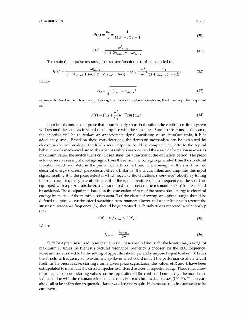
If an input consists of a pulse that is sufficiently short in duration, the continuous‐time system
will respond the same as it would to an impulse with the same area. Since the response is the same,
the objective will be to replace an approximate signal consisting of an impulses train, if h is
adequately small. Based on these considerations, the damping mechanism can be explained by
electro‐mechanical analogy: the RLC circuit response could be compared de facto to the typical
behaviour of a mechanical tuned absorber. As vibrations occur and the strain deformation reaches its
maximum value, the switch turns on (closed state) for a fraction of the excitation period. The piezo
actuator receives as input a voltage signal from the sensor; the voltage is generated from the structural
vibration which will deform the piezo that will convert mechanical energy of the structure into
electrical energy (“direct” piezoelectric effect). Instantly, the circuit filters and amplifies this input
signal, sending it to the piezo actuator which reacts to the vibrations (“converse” effect). By tuning
the resonance frequency fshunt of this circuit to the open‐circuit resonance frequency of the structure
equipped with a piezo transducer, a vibration reduction next to the resonant peak of interest could
be achieved. The dissipation is based on the conversion of part of the mechanical energy to electrical
energy by means of the resistive component R of the circuit. Anyway, an optimal range should be
defined to optimize synchronized switching performance: a lower and upper limit with respect the
structural resonance frequency (fstr) should be guaranteed. A thumb‐rule is reported in relationship
(35):
10𝑓 𝑓 50𝑓 (35)
where:
𝑓𝜔
2𝜋 (36)
Such best practise is used to set the values of these spectral limits: for the lower limit, a target of
maximum 10 times the highest structural resonance frequency is choosen for the RLC frequency.
More arbitrary is used to be the setting of upper threshold, generally imposed equal to about 50 times
the structural frequency so to avoid any spillover effect could inhibit the performance of the circuit
itself. In the present case, starting from a given piezo capacitance, the values of R and L have been
extrapolated to maximize the circuit impedance enclosed in a certain spectral range. These rules allow
in principle to choose starting values for the application of the control. Theoretically, the inductance
values in line with the resonance frequencies can also reach impractical values (100 H). This occurs
above all at low vibration frequencies: large wavelengths require high masses (i.e., inductances) to be
cut down.
Fluids 2020, 5, 183 10 of 20
4. Case Study: Cantilever Beam
4.1. FE Model Order Reduction
The benchmark chosen as test article for this study is an aluminum beam with thickness of 2
mm, and total dimensions of 250 × 30 mm. The beam is clamped on one edge and free on the other
one. A simple FE model representing these characteristics (geometric data, mechanical properties,
boundary conditions) has been built up: the main FEM properties are listed in the Table 1 while the
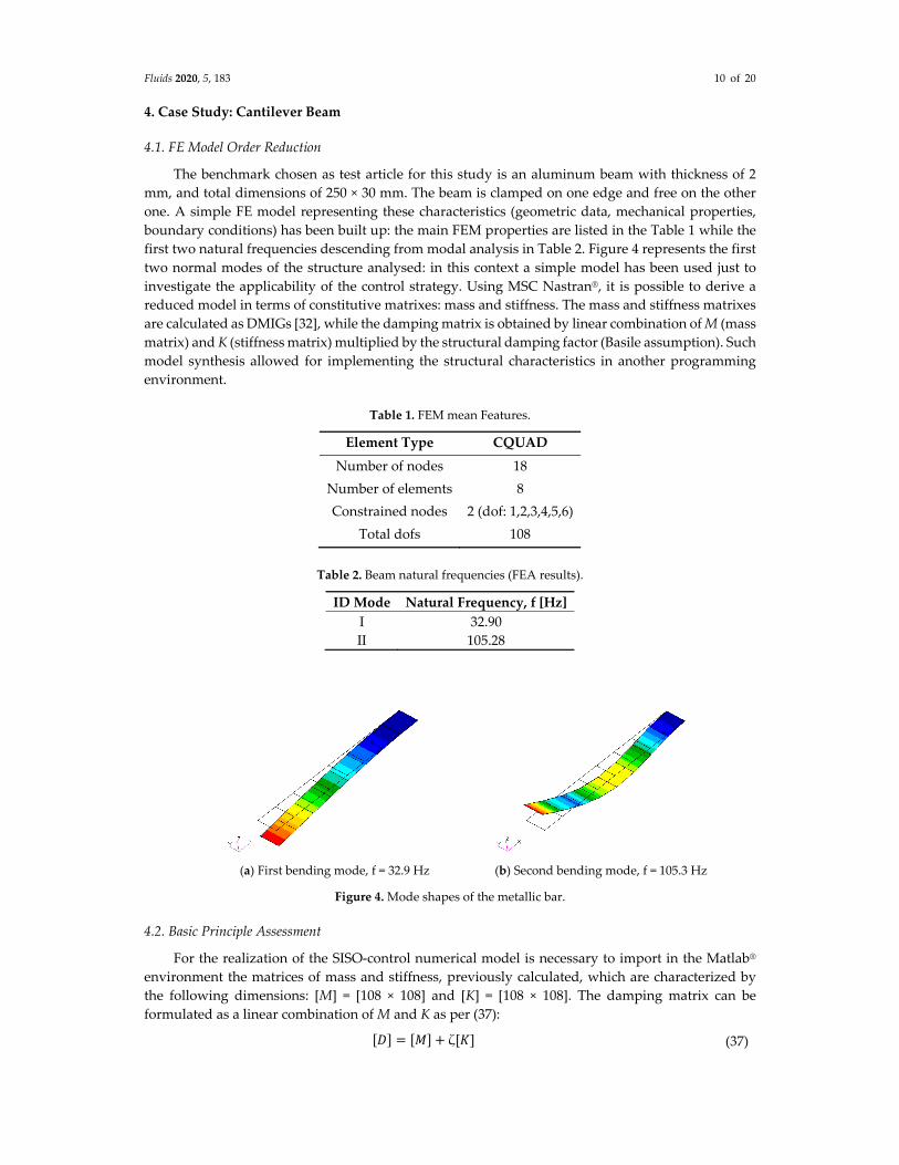
first two natural frequencies descending from modal analysis in Table 2. Figure 4 represents the first
two normal modes of the structure analysed: in this context a simple model has been used just to
investigate the applicability of the control strategy. Using MSC Nastran®, it is possible to derive a
reduced model in terms of constitutive matrixes: mass and stiffness. The mass and stiffness matrixes
are calculated as DMIGs [32], while the damping matrix is obtained by linear combination of M (mass
matrix) and K (stiffness matrix) multiplied by the structural damping factor (Basile assumption). Such
model synthesis allowed for implementing the structural characteristics in another programming
environment.
Table 1. FEM mean Features.
Element Type CQUAD
Number of nodes 18
Number of elements 8
Constrained nodes 2 (dof: 1,2,3,4,5,6)
Total dofs 108
Table 2. Beam natural frequencies (FEA results).
ID Mode Natural Frequency, f [Hz]
I 32.90
II 105.28
(a) First bending mode, f = 32.9 Hz (b) Second bending mode, f = 105.3 Hz
Figure 4. Mode shapes of the metallic bar.
4.2. Basic Principle Assessment
For the realization of the SISO‐control numerical model is necessary to import in the Matlab®
environment the matrices of mass and stiffness, previously calculated, which are characterized by
the following dimensions: [M] = [108 × 108] and [K] = [108 × 108]. The damping matrix can be
formulated as a linear combination of M and K as per (37):
𝐷 𝑀 ζ 𝐾 (37)
Fluids 2020, 5, 183 11 of 20
where ζ (assumed equal to 0.01) is the structural damping coefficient. At the end, three matrixes
having the same size [108 × 108] in agreement with the 6 DOFs of each node have been imported
within Matlab®. These matrixes have been initially calculated for a free‐free structure beam but in this
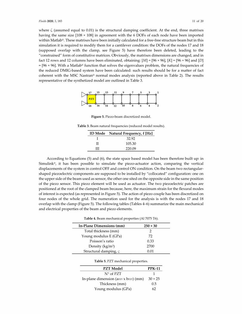
simulation it is required to modify them for a cantilever condition: the DOFs of the nodes 17 and 18
(supposed overlap with the clamp, see Figure 5) have therefore been deleted, leading to the
“constrained” form of constitutive matrices. Obviously, the matrixes dimensions are changed, and in
fact 12 rows and 12 columns have been eliminated, obtaining: [M] = [96 × 96], [K] = [96 × 96] and [D]
= [96 × 96]. With a Matlab® function that solves the eigenvalues problem, the natural frequencies of
the reduced DMIG‐based system have been calculated: such results should be for a matter of fact
coherent with the MSC Nastran® normal modes analysis (reported above in Table 2). The results
representative of the synthetized model are outlined in Table 3.
Figure 5. Piezo‐beam discretized model.
Table 3. Beam natural frequencies (reduced model results).
ID Mode Natural Frequency, f [Hz]
I 32.92
II 105.30
III 220.09
According to Equations (5) and (6), the state space based model has been therefore built up: in
Simulink®, it has been possible to simulate the piezo‐actuator action, comparing the vertical
displacements of the system in control OFF and control ON condition. On the beam two rectangular‐
shaped piezoelectric components are supposed to be installed by “collocated” configuration: one on
the upper side of the beam used as sensor, the other one sited on the opposite side in the same position
of the piezo sensor. This piezo element will be used as actuator. The two piezoelectric patches are
positioned at the root of the clamped beam because, here, the maximum strain for the flexural modes
of interest is expected (as represented in Figure 5). The action of piezo couple has been discretized on
four nodes of the whole grid. The numeration used for the analysis is with the nodes 17 and 18
overlap with the clamp (Figure 5). The following tables (Tables 4–6) summarize the main mechanical
and electrical properties of the beam and piezo elements.
Table 4. Beam mechanical properties (Al 7075 T6).
In-Plane Dimensions (mm) 250 × 30
Total thickness (mm) 2
Young modulus E (GPa) 72
Poisson’s ratio 0.33
Density (kg/m3) 2700
Structural damping, ς 0.01
Table 5. PZT mechanical properties.
PZT Model PPK-11
N° of PZT 1
In‐plane dimension (aPZT x bPZT) (mm) 30 × 25
Thickness (mm) 0.5
Young modulus (GPa) 62
PZT
17
18
1
2
3
4
5
6
7
8
9
10
11
12
13
14
15
16

Fluids 2020, 5, 183 12 of 20
Poisson ratio 0.33
Density (kg/m3) 8000
Table 6. PZT electro‐mechanical properties.
Property Value
PZT Coefficient g31 (V/m) −8.0 × 10⁻³
PZT coefficient d31 (m/V) −350 × 10−12
PZT coefficient d33 (m/V) 680 × 10−12
Relative dielectric constant 5000
The cyclic flow is described in few key‐steps. A swept‐sine signal source that causes beam’s
vibrations has been considered to excite the interest spectral bandwidth [0, 100 Hz] (Figure 6). The
state‐space logical block gives as output 16 displacements and 16 velocities. The output is controlled
by the matrix [C] in Equation (33). The output of the derivative block is the strain where the piezo‐
sensor is located. Such a value is passed to the piezo‐sensor logical block, to calculate the equivalent
voltage by Equation (12) (“direct” effect). The output signal is then sent to the RLC control circuit,
implemented with a transfer function and a gain that simulate circuit’s impedance; the signal
becomes the voltage field input of piezo‐actuator block where the force transmitted by piezo ‐actuator
to structure is calculated with Equation (16) (“inverse” effect). The force is then sent in feed‐back to
the external noise and summed with it: the output force level should normally be multiplied by the
gain factor of the piezo amplifier. Initially, this gain is considered unitary. In this way, the effective
force is decreased and used as new input to the state‐space block.
Figure 6. Closed loop Simulink® model.
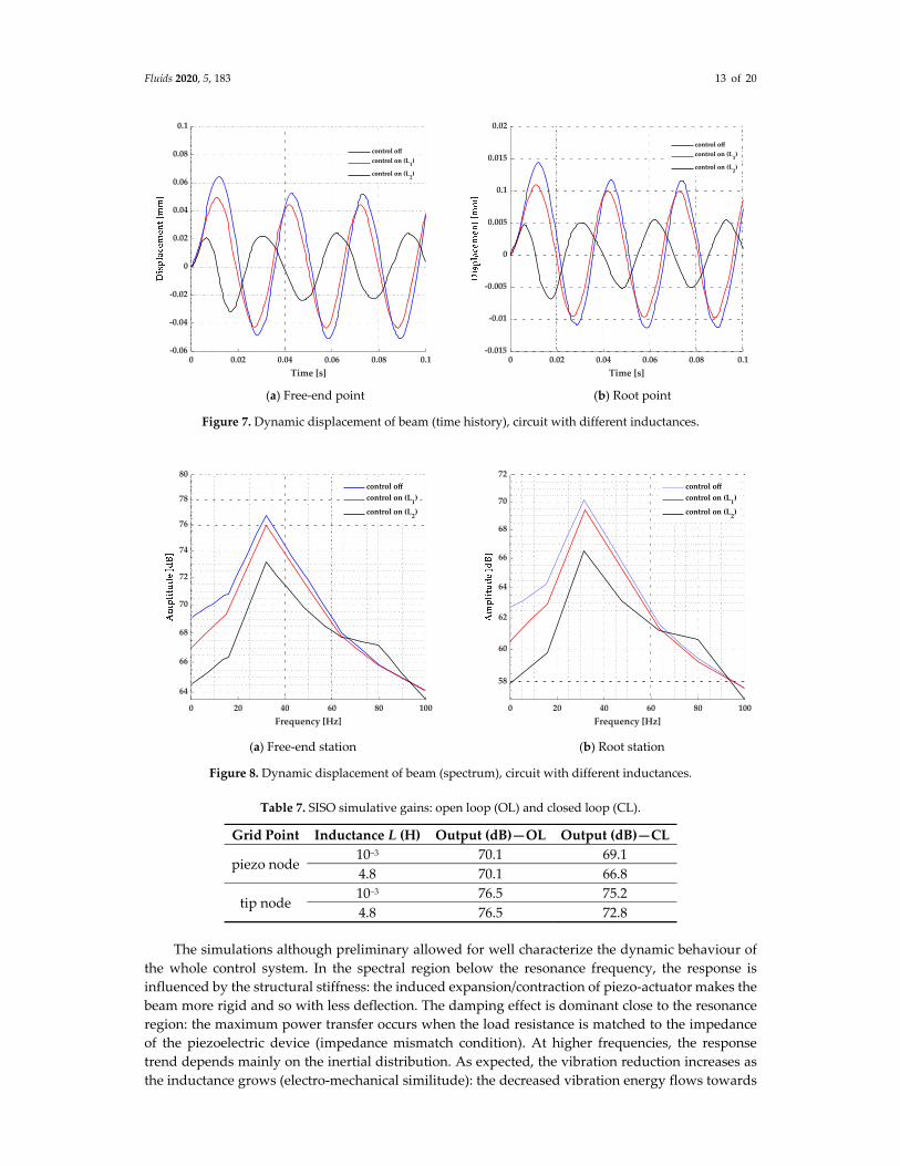
The run simulations have been performed just for two values of inductance L, as detailed in
Table 7. The performance results have been compared in Figures 7 and 8, in particular calculating
both the root and tip modal displacement. The outcomes are reported in time domain and as FFT as
well for the evaluation of the methodology.
Fluids 2020, 5, 183 13 of 20
(a) Free‐end point (b) Root point
Figure 7. Dynamic displacement of beam (time history), circuit with different inductances.
(a) Free‐end station (b) Root station
Figure 8. Dynamic displacement of beam (spectrum), circuit with different inductances.
Table 7. SISO simulative gains: open loop (OL) and closed loop (CL).
Grid Point Inductance L (H) Output (dB)—OL Output (dB)—CL
piezo node 10−3 70.1 69.1
4.8 70.1 66.8
tip node 10−3 76.5 75.2
4.8 76.5 72.8
The simulations although preliminary allowed for well characterize the dynamic behaviour of
the whole control system. In the spectral region below the resonance frequency, the response is
influenced by the structural stiffness: the induced expansion/contraction of piezo‐actuator makes the
beam more rigid and so with less deflection. The damping effect is dominant close to the resonance
region: the maximum power transfer occurs when the load resistance is matched to the impedance
of the piezoelectric device (impedance mismatch condition). At higher frequencies, the response
trend depends mainly on the inertial distribution. As expected, the vibration reduction increases as
the inductance grows (electro‐mechanical similitude): the decreased vibration energy flows towards
0 0.02 0.04 0.06 0.08 0.1
Time [s]
-0.06
-0.04
-0.02
0
0.02
0.04
0.06
0.08
0.1
control off
control on (L1)
control on (L2)
0 0.02 0.04 0.06 0.08 0.1
Time [s]
-0.015
-0.01
-0.005
0
0.005
0.1
0.015
0.02
control off
control on (L1)
control on (L2)
0 20 40 60 80 100
Frequency [Hz]
64
66
68
70
72
74
76
78
80
control off
control on (L1)
control on (L2)
0 20 40 60 80 100
Frequency [Hz]
58
60
62
64
66
68
70
72
control off
control on (L1)
control on (L2)
Fluids 2020, 5, 183 14 of 20
higher frequencies but at the same time the secondary resonance frequencies tend to shift to lower
values. For this reason, a remarkable change of transfer function trend of L2‐configuration after 60 Hz
is observable in Figure 8. The second mode shape originally at about 105 Hz becomes next to 80 Hz.
Therefore, the optimal choice of the inductance value is crucial for the dynamic stability of the
structure: if on the one hand a good reduction of the vibration is appreciated, on the other side
secondary modal shapes may appear close in bandwidth. Finally, a dynamic gain up to 3 dB has been
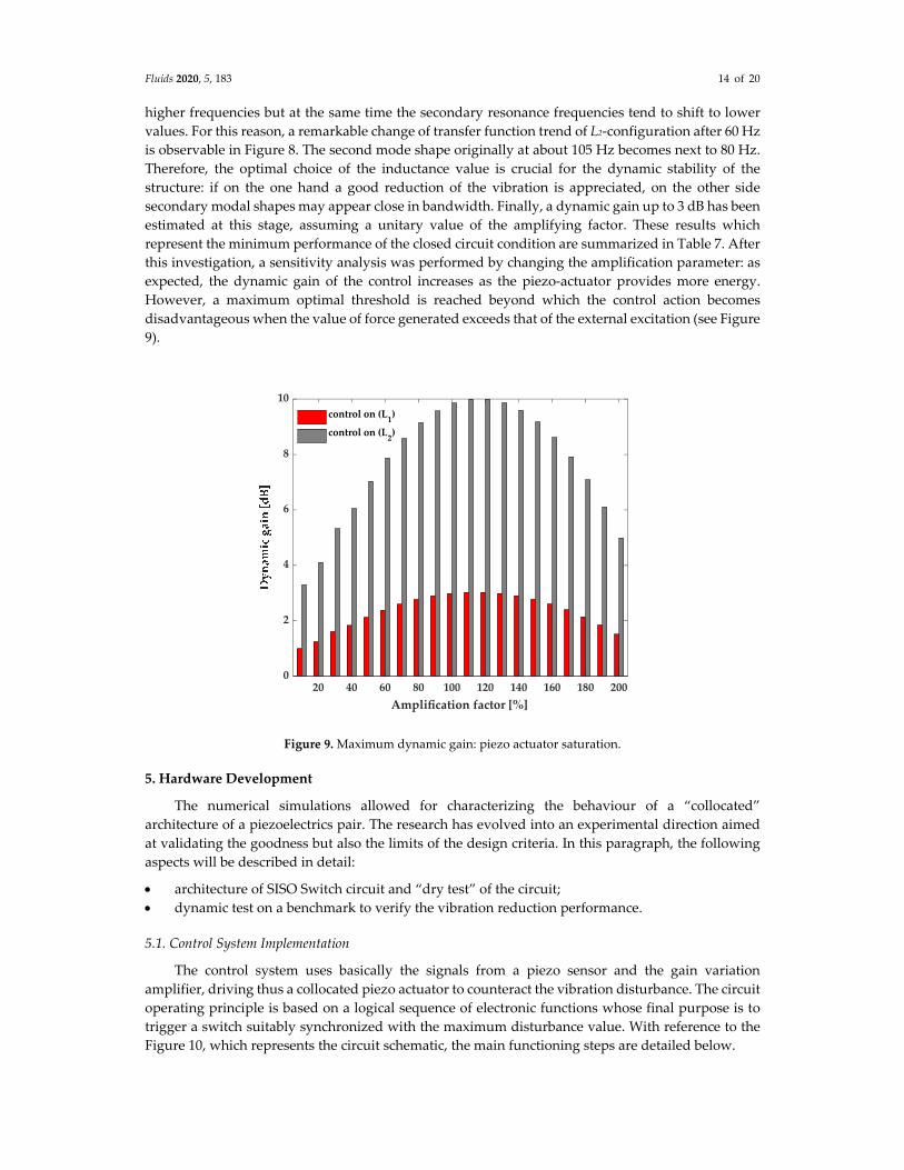
estimated at this stage, assuming a unitary value of the amplifying factor. These results which
represent the minimum performance of the closed circuit condition are summarized in Table 7. After
this investigation, a sensitivity analysis was performed by changing the amplification parameter: as
expected, the dynamic gain of the control increases as the piezo‐actuator provides more energy.
However, a maximum optimal threshold is reached beyond which the control action becomes
disadvantageous when the value of force generated exceeds that of the external excitation (see Figure
9).
Figure 9. Maximum dynamic gain: piezo actuator saturation.
5. Hardware Development
The numerical simulations allowed for characterizing the behaviour of a “collocated”
architecture of a piezoelectrics pair. The research has evolved into an experimental direction aimed
at validating the goodness but also the limits of the design criteria. In this paragraph, the following
aspects will be described in detail:
architecture of SISO Switch circuit and “dry test” of the circuit;
dynamic test on a benchmark to verify the vibration reduction performance.
5.1. Control System Implementation
The control system uses basically the signals from a piezo sensor and the gain variation
amplifier, driving thus a collocated piezo actuator to counteract the vibration disturbance. The circuit
operating principle is based on a logical sequence of electronic functions whose final purpose is to
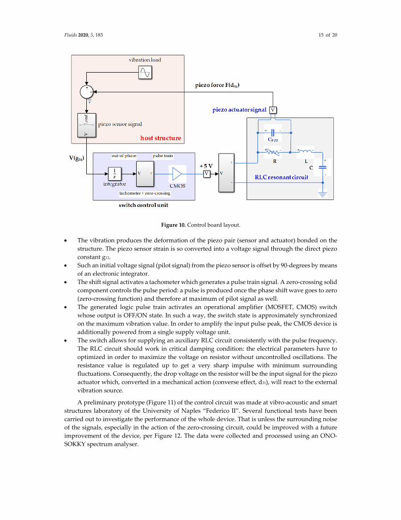
trigger a switch suitably synchronized with the maximum disturbance value. With reference to the
Figure 10, which represents the circuit schematic, the main functioning steps are detailed below.
20 40 60 80 100 120 140 160 180 200
Amplification factor [%]
0
2
4
6
8
10
control on (L1)
control on (L2)
Fluids 2020, 5, 183 15 of 20
Figure 10. Control board layout.
The vibration produces the deformation of the piezo pair (sensor and actuator) bonded on the
structure. The piezo sensor strain is so converted into a voltage signal through the direct piezo
constant g13.
Such an initial voltage signal (pilot signal) from the piezo sensor is offset by 90‐degrees by means
of an electronic integrator.
The shift signal activates a tachometer which generates a pulse train signal. A zero‐crossing solid
component controls the pulse period: a pulse is produced once the phase shift wave goes to zero
(zero‐crossing function) and therefore at maximum of pilot signal as well.
The generated logic pulse train activates an operational amplifier (MOSFET, CMOS) switch
whose output is OFF/ON state. In such a way, the switch state is approximately synchronized
on the maximum vibration value. In order to amplify the input pulse peak, the CMOS device is
additionally powered from a single supply voltage unit.
The switch allows for supplying an auxiliary RLC circuit consistently with the pulse frequency.
The RLC circuit should work in critical damping condition: the electrical parameters have to
optimized in order to maximize the voltage on resistor without uncontrolled oscillations. The
resistance value is regulated up to get a very sharp impulse with minimum surrounding
fluctuations. Consequently, the drop voltage on the resistor will be the input signal for the piezo
actuator which, converted in a mechanical action (converse effect, d31), will react to the external
vibration source.
A preliminary prototype (Figure 11) of the control circuit was made at vibro‐acoustic and smart
structures laboratory of the University of Naples “Federico II”. Several functional tests have been
carried out to investigate the performance of the whole device. That is unless the surrounding noise
of the signals, especially in the action of the zero‐crossing circuit, could be improved with a future
improvement of the device, per Figure 12. The data were collected and processed using an ONO‐
SOKKY spectrum analyser.

Fluids 2020, 5, 183 16 of 20
Figure 11. SISO control layout.
Figure 12. Input signal and logical switch for the RLC excitation.
5.2. Experimental Results
Test on Cantilever Beam
Once the logical functions were verified, a simple dynamic test was carried out on an
instrumented metallic bar. Both time histories and spectra have been analysed in order to characterize
the effect of the control on the disturbance. The structure was excited by a piezoelectric ceramic patch
bonded on its upper surface, driven by a 200 mV (peak‐to‐peak) sweep signal. A preliminary dry run
is carried out to find the optimal voltage level of excitation: low voltage levels are preferable as an
excessively amplified signal could introduce background noise components such as to affect the
measurement. An electro‐mechanical excitation, i.e., a shaker, has therefore been applied in order to
insert a greater energy level into the system. Due to the cantilever arrangement, the maximum
deformation is expected near the constraint. Such a primary source of disturbance is driven by an
appropriate impedance matching circuit and voltage transformers. The ONO‐SOKKY spectrum
analyzer that can provide swept‐sine, chirp, and random excitation was used as source control.
Vertical point response (acceleration, velocity, and displacement) has been detected through a laser
vibrometer with respect to the free‐tip of the beam. The transfer function has been therefore assessed
with respect the load cell signal. A schematic for the test‐set up in the following testing activities is
presented in Figure 13. A non‐contact measurement technique allowed for not affecting mass
distribution and therefore the modal characteristics of bar. According to the numerical model
0 0.01 0.02 0.03 0.04 0.05 0.06 0.07 0.08 0.09 0.1
Time [s]
-10
-7.5
-5
-2.5
0
2.5
5
7.5
10
12.5
15
pilot signal
out-of-phase signal
zero-crossing pulse train

Fluids 2020, 5, 183 17 of 20
evaluation, the experimental investigation was carried out by choosing two inductance value (0.001
H and 5 H) and assuming an unitary amplification factor. In order to assess the capabilities of the
control system, the frequency response function representative of the free‐end vibration has been
recorded in both on and off control conditions. Measurements without considering any additional
amplification effect have shown a vibration reduction of the order of 3 dB, emitted by the bar when
excited by a swept‐sine excitation, Figure 14a. The experimental evidence has demonstrated the same
trend already assessed by means of theoretical models: the closed‐loop activation influences the
dynamic behaviour of the system even outside the controlled frequency. The inductance like an
inertial element generate a shift of the secondary natural frequencies and for this reason an inversion
of the amplitude curves can be observed after about 60 Hz. However, the controlled frequency
remains almost the same: in resonance conditions, the more noticeable effect is introduced just by the
modal damping. At the lower frequencies, the system exhibits a large stiffness thanks to the action of
a piezo‐actuator which leads to counteracting the vibration. The main purpose is just to verify the
functioning of the control platform: performance improvement, indirect spillover analysis,
component optimization will be the subject of future analysis. The control board operation has been
checked before without applying the signal amplifier: by increasing the gain to 95% of amplifier
power (Figure 14b), the reduction reaches 12 dB, in line with numerical expectations.
Figure 13. Diagram of the test equipment and control system.
(a) piezo response (no amplification effect) (b) peak reduction (piezo amplification)
Figure 14. Vibration test performing: laser vibrometer response.

Fluids 2020, 5, 183 18 of 20
6. Conclusions
The present work presented an innovative technique for active vibration control using a SISO
“collocated” strategy. Using the capabilities of a standard FEM code, the possibility of numerically
simulating the dynamic behavior of the structure together with a control law has been demonstrated,
assuming that a proper model of the piezo‐sensor and piezo‐actuator was defined. A multi‐dofs fully
coupled system has been designed applying a finite element formulation. A full numerical procedure,
according to characteristics equations describing the fully coupled system has been then realized in
a Simulink® environment. The structural matrices, i.e., DMIG, have been extracted from Nastran® and
separately reassembled considering also the electro‐mechanical coupling terms to be added: in
particular, 2D piezo strain actuation theory has been modelled with reference to a simple system. The
effects exerted by piezo on the structure have been applied as actuation forces at the piezo nodes
interface (converse piezoelectric effect). Similarly, the sensing has been modelled with a 2D
piezoelectric constitutive equation based on voltage rates (direct piezoelectric effect). As core of the
research, a cheap circuit, based on a tachometer and CMOS devices has been realised to implement
the synchronized shunt control. The tachometer device can produce a pulse train signal triggering
the CMOS flawlessly synchronized with the zero‐crossing of the input. This model could be used as
design and optimization tool to determine, for example, the number and the positions of the
piezoelectrics in order to attenuate the vibration levels at specific frequency ranges. Average
vibration reductions of about 3 dB have been assessed without the additional effect of an
amplification factor: a sensitivity analysis allowed to forecast a dynamic gain of up to 10 dB. A
conceptual hardware board has been realized, experimentally demonstrating the methodology for
an aluminium beam. In more detail, the piezo‐actuator has been controlled by an external RLC‐based
circuit. Sensible vibration reduction up to 3 dB without significant evidence of any loss of stability
has been assessed with respect to the first mode shape. The control board operation was checked
before without applying the signal amplifier: the performance of the piezo‐actuator alone has come
to a reduction of up to 3 dB. By increasing the gain to 95% of amplifier power, the reduction reaches
12 dB, in line with numerical expectations. The control system presented here was tested as a
preliminary prototype for future research activities. The main objective was just to validate the
feasibility system: the vibrations damping gained here is actually the result of a single piezo device,
without power amplification for its actuation. This strongly encourages testing systems with multiple
active elements. These capabilities may be applied to explore the opportunity to design and optimize
the number and position of the piezo in order to attenuate the vibro‐acoustic levels at particular mode
shapes. Moreover, current activities are addressed to assess the sound proofing capabilities of the
switching shunt device.
Author Contributions: Both authors (M.A. and M.V.) have equally contributed to this research paper. All
authors have read and agreed to the published version of the manuscript.
Funding: This research received no external funding.
Acknowledgments: The author M.A. thanks the contribution of the students Armando Franzone and Andrea
Larenza who collaborated on this topic during his research activities.
Conflicts of Interest: The authors declare no conflict of interest.
References
1. Crawley, E.F.; de Louis, J. Use of Piezoelectric Actuators as Elements of Intelligent Structures. AIAA J. 1989,
25, 1373–1385.
2. Kalaycıoğlu, S.; Misra, A. Approximate Solutions for Vibrations of Deploying Appendages. J. Guid. Control
Dyn. AIAA 1991, 14, 287–293.
3. Kalaycıoğlu, S.; Giray, M.M.; Asmer, H. Time Delay Control of Space Structures Using Embedded
Piezoelectric Actuators and Fiberoptic Sensors. In Proceedings of the SPIE’s 4th Annual Symposium on
Smart Structures and Materials, San Diego, CA, USA, 6 June 1997.

Fluids 2020, 5, 183 19 of 20
4. Suleman, A.; Costa, A.P.; Crawford, C.; Sedaghati, R. Wind Tunnel Aeroelastic Response of Piezoelectric
and Aileron Controlled 3‐D Wing. In Proceedings of the CanSmart Workshop Smart Materials and
Structures Proceedings, St‐Hubert, QC, Canada, 10–11 September 1998.
5. Lecce, L.; Concilio, A.; Del Gatto, F.S. Active control of noise and vibration on panels with a simple self‐
adaptive system using distributed piezoelectric devices. In Proceedings of the 2nd ATA International
Conference on Vehicle Comfort, Bologna, Italy, 14–16 October 1992; Volume 2, pp. 777–789.
6. Lecce, L.; De Bellis, L.; Miccoli, G. Active vibration and noise control of a stiffened panel by simple
piezoelectric devices. In Proceedings of the 2nd Conference on Recent Advances in Active Control of Sound
and Vibration, Blacksburg, VA, USA, 28–30 April 1993; Technomic Press: Lancaster, PA, USA, 1993; pp.
S28–S40.
7. Lesieutre, G.A. Vibration Damping and Control Using Shunted Piezoelectric Materials. Shock Vib. Dig. 1998,
30, 187–195.
8. Richard, C.; Guyomar, D.; Audigier, D.; Bassaler, H. Enhanced Semi Passive Damping Using Continuous
Switching of a Piezoelectric Device on an Inductor. In Proceedings of the SPIE, Damping and Isolation,
Newport Beach, CA, USA, 27 April 2000; Volume 3989, pp. 288–299.
9. Guyomar, D.; Badel, A.; Lefeuvre, E.; Richard, C. Toward energy harvesting using active materials and
conversion improvement by nonlinear processing. IEEE Trans. Ultrason. Ferroelectr. Freq. Control 2005, 52,
584–595, doi:10.1109/TUFFC.2005.1428041.
10. Ameduri, S.; Ciminello, M.; Sorrentino, A.; Concilio, A. Beam Vibrations Control through a Synchronised
Switched Shunt Resonator (SSSR) System. In Proceedings of the AIDAA XVIII National Congress, Volterra,
Italy, 19–22 September 2005.
11. Ciminello, M.; Ameduri, S.; Concilio, A. FE Modelling of an Innovative Vibration Control Shunt Technique
J. Intell. Mater. Syst. Struct. 2008, 19, 875–887.
12. Ciminello, M.; Ameduri, S.; Calabrò, A.; Concilio, A. Synchronised Switched Shunt Control Technique
Applied on a Cantilevered Beam: Numerical and Experimental Investigations. J. Intell. Mater. Syst. Struct.
2008, 19, 1089–1100.
13. Ciminello, M.; Lecce, L.; Ameduri, S.; Calabrò, A.; Concilio, A. Multi‐tone Switching Shunt Control by a
PZT Network Embedded into a Fiberglass Panel: Design, Manufacture and Test. J. Intell. Mater. Syst. Struct.
2009, 21, 437–451.
14. Viana, F.A.C.; Steffen, V., Jr. Multimodal vibration damping through piezoelectric patches and optimal
resonant shunt circuits. J. Braz. Soc. Mech. Sci. Eng. 2006, 28, 293–310.
15. Goldstein, A.L. Self‐Tuning Multimodal Piezoelectric Shunt Damping. J. Braz. Soc. Mech. Sci. Eng. 2011, 33,
428–436.
16. Heganna, S.S.; Joglekar, J.J. Active Vibration Control of Smart Structure using PZT Patches. In Proceedings
of the Twelfth International Multi‐Conference on Information Processing‐2016 (IMCIP‐2016), Bangalore,
India, 19–21 August 2016; Volume 89, pp. 710–715.
17. Hagood, N.W.; von Flotow, A. Damping of structural vibrations with piezoelectric materials and passive
electrical networks. J. Sound Vib. 1991, 146, 243–268.
18. Behrens, S.; Fleming, A.J.; Moheimani, S.O.R. Electromagnetic shunt damping. In Proceedings of the 2003
IEEE/ASME International Conference on Advanced Intelligent Mechatronics (AIM 2003), Kobe, Japan, 20–
24 July 2003; Volume 1–2, pp. 1145–1150.
19. Pernod, L.; Lossouarn, B.; Astolfi, J.‐A.; Deü, J.‐F. Passive vibration damping of hydrofoils using resonant
piezoelectric shunt. In Proceedings of the 9th ECCOMAS Thematic Conference on Smart Structures and
Materials, SMART 2019, Paris, France, 8–12 July 2019.
20. Huang, T.; Ichchou, M.N.; Bareille, O.; Collet, M.; Ouisse, M. Traveling wave control in thin‐walled
structures through shunted piezoelectric patches. Mech. Syst. Sign. Process. 2013, 39, 59–79.
21. Lossouarn, B.; Deü, J.‐F.; Kerschen, G. A fully passive nonlinear piezoelectric vibration absorber. Philos.
Trans. R. Sci. A Math. Phys. Eng. Sci. 2018, 376, 20170142, doi:10.1098/rsta.2017.0142.
22. Yan, B.; Wang, K.; Hu, Z.; Wu, C.; Zhang, X. Shunt Damping Vibration Control Technology: A Review.
Appl. Sci. 2017, 7, 494.
23. Marakakis, K.; Tairidis, G.K.; Koutsianitis, P.; Stavroulakis, G.E. Shunt Piezoelectric Systems for Noise and
Vibration Control: A Review. Front. Built Environ. 2019, 5, 64, doi:10.3389/fbuil.2019.00064.

Fluids 2020, 5, 183 20 of 20
24. Viscardi, M.; Arena, M.; Ciminello, M. A modified Shunted Switch Architecture (SSSA) for active vibration
control. In Proceedings of the SPIE 10595, Active and Passive Smart Structures and Integrated Systems XII,
Denver, CO, USA, 28 March 2018.
25. Baker, R.J. CMOS: Circuit Design, Layout, and Simulation, 4th ed.; IEEE Press Series on Microelectronic
Systems; IEEE Press: Piscataway, NJ, USA, 2019.
26. Reaves, M.C.; Horta, L.G. Piezoelectric Actuator Modeling Using MSC/NASTRAN and MATLAB; NASA
Langley Research Center: Hampton, VA, USA, 2003.
27. Posbergh, T.A.; Trimboli, M.S.; Duke, J.P. A Control Formulation for Vibration Absorbers. In Proceedings
of the American Control Conference, Boston, MA, USA, 26–28 June 1991; pp. 2481–2482.
28. Sollo, A.; Lecce, L.; Quaranta. V.; Doelman, N.; Doppenberg, E. Active Noise Control on ATR Fuselage
Mock‐up by Piezoceramic Actuators. In Proceedings of the 4th AIAA/CEAS Aeroacoustics Conference,
Toulouse, France, 2–4 June 1998; pp. 174–181.
29. Baz, A.; Poh, S. Performance of an Active Control System with Piezoelectric Actuators J. Sound Vib. 1988,
126, 327–343.
30. Anderson, E.H.; Crawley, E.F. Piezoceramic Actuation of One‐ and Two‐Dimensional Structures, Space Systems
Laboratory. Report N. 5‐89; MIT: Cambridge, MA, USA, 1989.
31. Wada, B.K.; Fanson, J.L.; Crawley, E.F. Adaptive Structures. J. Intell. Mater. Struct. 1990, 1, 157–174.
32. MSC Nastran®. Quick Reference Guide; MSC Nastran: Newport Beach, CA USA, 2019.
Publisher’s Note: MDPI stays neutral with regard to jurisdictional claims in published maps and institutional
affiliations.
© 2020 by the authors. Licensee MDPI, Basel, Switzerland. This article is an open access
article distributed under the terms and conditions of the Creative Commons Attribution
(CC BY) license (http://creativecommons.org/licenses/by/4.0/).