sirius motor management and control devices · sirius motor management and control devices ......
TRANSCRIPT

3/56
Motor management and control devicesSIMOCODE pro
SIRIUS Motor Management and Control Devices
Siemens Energy & Automation, Inc.Industrial Controls Catalog – Overloads Supplement
SiemIndus
Overview
SIMOCODE pro is a flexible, modular motor management sys-tem for motors with constant speeds in the low-voltage perfor-mance range. It optimizes the connection between the control system and motor starter, increases plant availability and allows significant savings to be made for startup, operation and main-tenance of a system.
When SIMOCODE pro is installed in the low-voltage control cabinet, it is the intelligent interface between the higher-level automation system and the motor starter and includes the following:• Multifunctional, solid-state full motor protection which is inde-
pendent of the automation system• Flexible software instead of hardware for the motor control• Detailed operational, service and diagnostics data• Open communication via PROFIBUS DP, the standard for field-
bus systems
Benefits
General customer benefits• Integrating the motor starter into the process control system via
a bus significantly reduces the wiring outlay between the motor starter and PLC
• Distribution of the automated processes by means of config-urable control and monitoring functions in the starter saves re-sources in the automation system and ensures full functionality and protection of the starter even if the control system or bus system fails
• The acquisition and monitoring of operational, service and di-agnostics data in the starter and process control system in-creases system availability as well as maintenance and ser-vice-friendliness
• The high degree of modularity allows users to perfectly imple-ment their plant-specific requirements for each motor starter
• The SIMOCODE pro system offers functionally scaleable and space-saving solutions for each customer’s application
• The replacement of the control circuit hardware with software decreases the number of hardware components and wiring re-quired and this limits the necessary stocking requirements and potential wiring errors
• The use of solid-state full motor protection permits better utili-zation of the motors and ensures long-term stability of the trip-ping characteristic and reliable tripping even after years of ser-vice
Multifunctional, solid-state full motor protection for rated motor currents up to 820 A
SIMOCODE pro offers comprehensive protection of the motor starter by means of a combination of different, multi-step and de-layable protection and monitoring functions:• Inverse-time delayed solid-state overload protection
(Class 5 ... 40)• Thermistor motor protection• Phase failure / unbalance protection• Stall protection• Monitoring of adjustable limit values for the motor current• Voltage and power monitoring• Monitoring of the power factor (cos-phi or loss of load)• Earth fault monitoring• Temperature monitoring, e.g., over PT100/PT1000• Monitoring of operating hours, downtime and number of starts
etc.
Recording of measurement curvesSIMOCODE pro can record gradients and can therefore present the progression of motor current during motor start-up.
Flexible motor control implemented with software (instead of comprehensive hardware interlocks)
Many predefined motor control functions have already been in-tegrated into SIMOCODE pro, including all necessary logic op-erations and interlocks.• Across-the-line and reversing starters• Star-delta starters (also with direction reversal) • Two speeds, motors with separate windings (pole-changing
switch); also with direction reversal • Two speeds, motors with separate Dahlander windings (also
with direction reversal)• Positioner actuation• Solenoid valve actuation• Activation of a circuit-breaker• Soft starter actuation (also with direction reversal)
These control functions have been implemented by means of software and can be freely assigned to the inputs and outputs, and this control functionality can be done over Profibus.
These predefined control functions can also be flexibly adapted to each customer-specific configuration of a motor starter by means of freely configurable logic modules (truth tables, counters, timers, edge evaluation ...) and with the help of standard functions (power failure monitoring, emergency start, external faults ...).
SIMOCODE pro makes a lot of additional hardware and wiring in the control circuit unnecessary which results in a high level of standardization of the motor starter in terms of its design and cir-cuit diagrams.
Detailed operational, service and diagnostics data
SIMOCODE pro makes different operational, service and diag-nostics data available and helps to detect potential faults in time and to prevent them by means of preventative measures. In the event of a malfunction, a fault can be diagnosed, localized and rectified very quickly, and this minimizes potential downtime.
Operating data• Motor switching status derived from the current flow in the main
circuit• All current phases• All voltage phases• Active power, apparent power and power factor• Phase unbalance and phase sequence• Time to trip• Motor bearing or winding temperatures• Remaining cooling time etc.
Service data• Motor operating hours• Motor stop times• Number of motor starts• Number of overload trips• Internal comments stored in the device etc.
Diagnostic data• Numerous detailed early warning and fault messages• Internal device fault logging with time stamp• Time stamping of freely selectable staus, alarm or fault mes-
sages etc.
Siemens / Industrial Controls Previous folio: 3/45 IC 2006, 2/1
06IC.Supp.03_56.ps 7/13/06 6:56 PM Page 56
3/57
SIRIUS Motor Management and Control Devices
Inc.ment
Siemens Energy & Automation, Inc.Industrial Controls Catalog – Overloads Supplement
Motor management and control devicesSIMOCODE pro
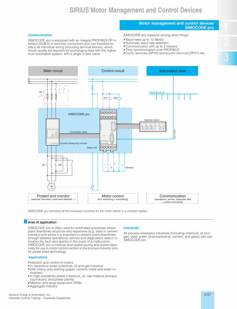
Communication
SIMOCODE pro is equipped with an integral PROFIBUS DP in-terface (SUB-D or terminal connection) and can therefore re-place all individual wiring (including terminal blocks), which would usually be required for exchanging data with the higher-level automation system, with a single 2-wire cable.
SIMOCODE pro supports among other things: • Baud rates up to 12 Mbit/s• Automatic baud rate detection• Communication with up to 3 masters• Time synchronization over PROFIBUS• Cyclic services (DPV0) and acyclic services (DPV1) etc.
SIMOCODE pro combines all the necessary functions for the motor starter in a compact system
Area of application
SIMOCODE pro is often used for automated processes where plant downtimes would be very expensive (e.g. steel or cement industry) and where it is important to prevent plant downtimes through detailed operational, service and diagnostics data or to localize the fault very quickly in the event of a malfunction. SIMOCODE pro is modular and space-saving and suited espe-cially for use in motor control centers in the process industry and for power plant technology.
Applications
Protection and control of motors• In hazardous areas (chemical, oil and gas industry)• With heavy-duty starting (paper, cement, metal and water in-
dustries)• In high-availability plants (chemical, oil, raw material process-
ing industry, and power plants)• Medium and large equipment OEMs• Aggregate industry
Industries
All process-orientated industries (including chemical, oil and gas, steel, water, pharmaceutical, cement, and glass) can use SIMOCODE pro.
Siemens / Industrial Controls Previous folio: 3/46 IC 2006, 2/2
06IC.Supp.03_57.ps 7/13/06 6:56 PM Page 57

3/58
Motor management and control devicesSIMOCODE pro
SIRIUS Motor Management and Control Devices
Siemens Energy & Automation, Inc.Industrial Controls Catalog – Overloads Supplement
SiemIndus
Design
General
SIMOCODE pro is a modular-designed motor management sys-tem which can be subdivided into two devices, each having dif-ferent functional scopes:• SIMOCODE pro C and• SIMOCODE pro V
Both devices or systems are made up of different hardware components (modules):
Each system is comprised of one basic unit as the main compo-nent and a separate current measuring module for each starter. The two modules are connected electrically through the system interface with a connection cable. The electronic base unit (pro C or pro V) may be able to be mounted directly on top of the cur-rent transformer to save panel space or separately (side by side). The current measuring module must be selected in accor-dance with the motor current to be monitored.
As an option, an operator panel can be connected through a second connection cable to the basic unit which can be mounted in the door of the control cabinet. The electrical supply for both the current measuring module and the operator panel is provided by the basic unit over the connection cable. Apart from the inputs and outputs available on the basic unit, additional inputs/outputs and other functions can be added to Basic Unit 2 (SIMOCODE pro V) using optional expansion modules.
All modules are interconnected using connection cables. The connection cables are available in several lengths. The maxi-mum distance between the modules (e.g. between the basic unit and the current measuring module) is 2 m. The overall length of the connection cables in a system is not permitted to exceed 3 m.
SIMOCODE pro is designed for mixed operation
In accordance with functional requirements, the two different systems can be used simultaneously without any problems and without any additional outlay in a low-voltage system. SIMOCODE pro C is fully upward compatible to SIMOCODE pro V. The same components are used. The para-meterization of SIMOCODE pro C can be transferred without any problems. Removable terminals and the terminal designations are identical in both systems.
1) Please see accessories.
SIMOCODE pro C, Basic Unit 1
The compact system for• across-the-line and reversing starters or• for activating a circuit breaker (MCCB)
There are 4 binary inputs, 3 monostable relay outputs and one thermistor connection (binary PTC).
Basic Unit 1 is available in two different variants for the following supply voltages:• DC 24 V• AC/DC 110 ... 240 V
SIMOCODE pro C, Basic Unit 1
Inputs:• 4 binary inputs, supplied internally with DC 24 V
Outputs:• 3 (2+1) monostable relay outputs
Thermistor connection for binary PTC
PROFIBUS interface:• 9-pin sub D or• terminal connection
Connection of supply voltage:• DC 24 V or• AC/DC 110 ... 240 V
Test/Reset button
3 LEDs
2 system interfaces for connection• of a current measuring module and• an operator panel
Basic Unit 1 is suitable for mounting on standard 35 mm Din rail, or for panel mounting using the additional push-in lugs. 1)
System SIMOCODE pro C SIMOCODE pro V
Modules • Basic Unit 1 • Basic Unit 2• Current measuring module • Current measuring module or
current/voltage measuring module
• Operator panel (optional) • Operator panel (optional)• Expansion modules (optional)
Siemens / Industrial Controls Previous folio: 3/47 IC 2006, 2/3
06IC.Supp.03_58.ps 7/13/06 6:56 PM Page 58
3/59
SIRIUS Motor Management and Control Devices
Inc.ment
Siemens Energy & Automation, Inc.Industrial Controls Catalog – Overloads Supplement
Motor management and control devicesSIMOCODE pro
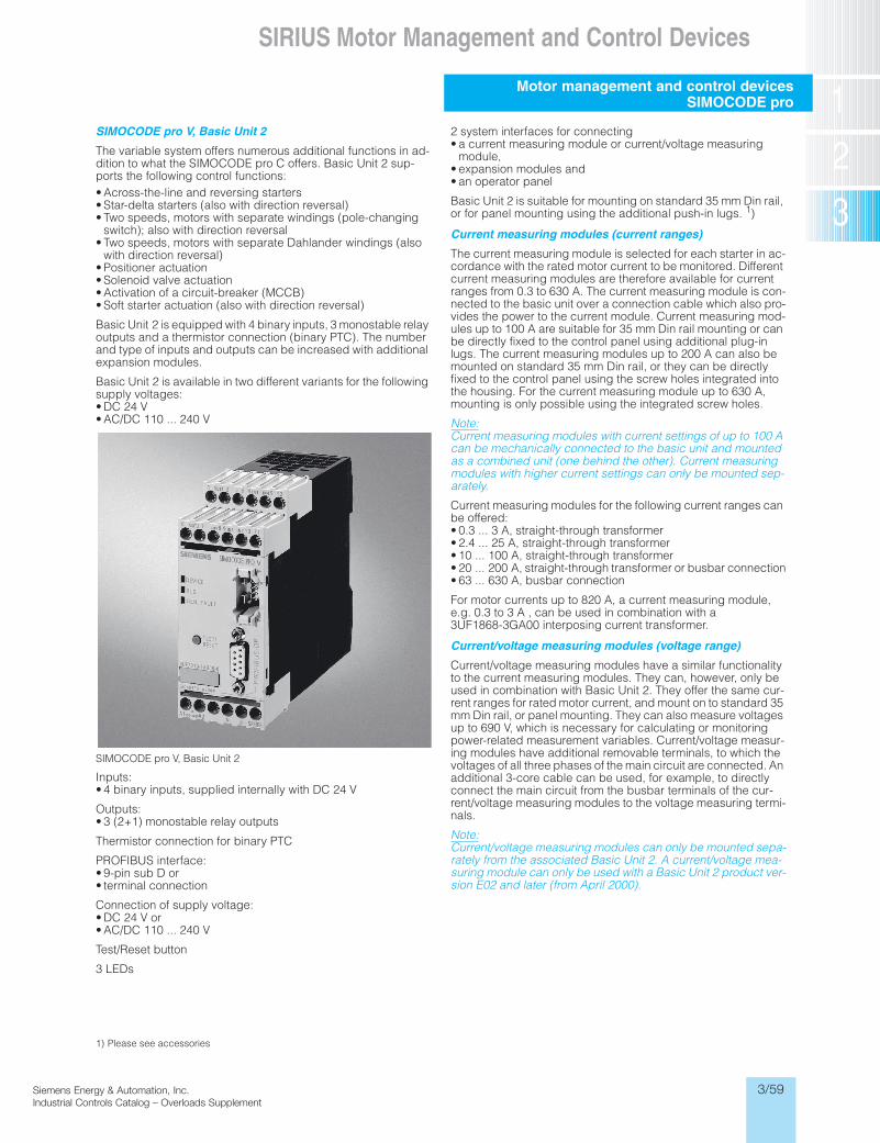
SIMOCODE pro V, Basic Unit 2
The variable system offers numerous additional functions in ad-dition to what the SIMOCODE pro C offers. Basic Unit 2 sup-ports the following control functions:• Across-the-line and reversing starters• Star-delta starters (also with direction reversal)• Two speeds, motors with separate windings (pole-changing
switch); also with direction reversal• Two speeds, motors with separate Dahlander windings (also
with direction reversal)• Positioner actuation• Solenoid valve actuation• Activation of a circuit-breaker (MCCB)• Soft starter actuation (also with direction reversal)
Basic Unit 2 is equipped with 4 binary inputs, 3 monostable relay outputs and a thermistor connection (binary PTC). The number and type of inputs and outputs can be increased with additional expansion modules.
Basic Unit 2 is available in two different variants for the following supply voltages:• DC 24 V• AC/DC 110 ... 240 V
SIMOCODE pro V, Basic Unit 2
Inputs:• 4 binary inputs, supplied internally with DC 24 V
Outputs:• 3 (2+1) monostable relay outputs
Thermistor connection for binary PTC
PROFIBUS interface:• 9-pin sub D or• terminal connection
Connection of supply voltage:• DC 24 V or• AC/DC 110 ... 240 V
Test/Reset button
3 LEDs
1) Please see accessories
2 system interfaces for connecting• a current measuring module or current/voltage measuring
module,• expansion modules and• an operator panel
Basic Unit 2 is suitable for mounting on standard 35 mm Din rail, or for panel mounting using the additional push-in lugs. 1)
Current measuring modules (current ranges)
The current measuring module is selected for each starter in ac-cordance with the rated motor current to be monitored. Different current measuring modules are therefore available for current ranges from 0.3 to 630 A. The current measuring module is con-nected to the basic unit over a connection cable which also pro-vides the power to the current module. Current measuring mod-ules up to 100 A are suitable for 35 mm Din rail mounting or can be directly fixed to the control panel using additional plug-in lugs. The current measuring modules up to 200 A can also be mounted on standard 35 mm Din rail, or they can be directly fixed to the control panel using the screw holes integrated into the housing. For the current measuring module up to 630 A, mounting is only possible using the integrated screw holes.
Note:Current measuring modules with current settings of up to 100 A can be mechanically connected to the basic unit and mounted as a combined unit (one behind the other). Current measuring modules with higher current settings can only be mounted sep-arately.
Current measuring modules for the following current ranges can be offered:• 0.3 ... 3 A, straight-through transformer• 2.4 ... 25 A, straight-through transformer• 10 ... 100 A, straight-through transformer• 20 ... 200 A, straight-through transformer or busbar connection• 63 ... 630 A, busbar connection
For motor currents up to 820 A, a current measuring module, e.g. 0.3 to 3 A , can be used in combination with a 3UF1868-3GA00 interposing current transformer.
Current/voltage measuring modules (voltage range)
Current/voltage measuring modules have a similar functionality to the current measuring modules. They can, however, only be used in combination with Basic Unit 2. They offer the same cur-rent ranges for rated motor current, and mount on to standard 35 mm Din rail, or panel mounting. They can also measure voltages up to 690 V, which is necessary for calculating or monitoring power-related measurement variables. Current/voltage measur-ing modules have additional removable terminals, to which the voltages of all three phases of the main circuit are connected. An additional 3-core cable can be used, for example, to directly connect the main circuit from the busbar terminals of the cur-rent/voltage measuring modules to the voltage measuring termi-nals.
Note:Current/voltage measuring modules can only be mounted sepa-rately from the associated Basic Unit 2. A current/voltage mea-suring module can only be used with a Basic Unit 2 product ver-sion E02 and later (from April 2000).
Siemens / Industrial Controls Previous folio: 3/48 IC 2006, 2/4
06IC.Supp.03_59.ps 7/13/06 6:56 PM Page 59

3/60
Motor management and control devicesSIMOCODE pro
SIRIUS Motor Management and Control Devices
Siemens Energy & Automation, Inc.Industrial Controls Catalog – Overloads Supplement
SiemIndus
‘-‘
Module widths and current settings for the current measuring modules and the current/voltage measuring modules
Operator panel
The operator panel is used to control the motor starter and can replace all conventional pushbuttons and indicator lamps to save space. This means that SIMOCODE pro or the starter can be operated directly at the control cabinet and there is a PG/PC-Interface on the front of the operator panel for easier parameter-ization and diagnosis.
The operator panel is connected to the basic unit over a connec-tion cable from its rear system interface and is supplied electri-cally from the basic unit.
The operator panel has 5 freely assignable buttons and a total of 10 LEDs, of which 7 LEDs can be used as required and as-signed to any status signal.
The PC cable should be used with the PG/PC-Interface on the operator panel.
The operator panel can be mounted in the control cabinet door or the front plate of, for example, an MCC bucket and this satis-fies IP54 degree of protection with the system interface covered.
Operator panel for SIMOCODE pro
• 10 LEDs• Labeling strips• Test/Reset button• 4 control keys• 2 system interfaces, on the front with interface covers
Expansion modules for additional I/Os and functions
With Basic Unit 2 (SIMOCODE pro V), it is possible to expand the number and type of inputs and outputs in order to implement ad-ditional functions. Each expansion module has two system inter-faces on the front. The expansion module is connected through one system interface using a connection cable, and the other system interface connects to the Basic Unit 2. Further expansion modules or the operator panel can be connected in the same manner with the connection cables. The power supply for the ex-pansion modules is provided by the connection cable through Basic Unit 2.
All expansion modules are suitable for Din rail mounting or for panel mounting using the additional push-in lugs.1)
Overall width
45 mm 55 mm 120 mm 145 mm
Current measuring modules
Current/voltage measuring modules
Current setting To measure and monitor motor currents up to 820 A, matching 3UF1868-3GA00 inter-posing current trans-formers are available.
0.3 ... 3 A; 2.4 ... 25 A 10 ... 100 A 20 ... 200 A 63 ... 630 A
Straight-through transformers
Busbar connection
1) Please see accessories.
Siemens / Industrial Controls Previous folio: 3/49 IC 2006, 2/5
06IC.Supp.03_60.ps 7/13/06 6:56 PM Page 60

3/61
SIRIUS Motor Management and Control Devices
Inc.ment
Siemens Energy & Automation, Inc.Industrial Controls Catalog – Overloads Supplement
Motor management and control devicesSIMOCODE pro
Expansion with additional binary I/Os through digital mod-ules
Up to two digital modules can be used to add additional binary inputs and relay outputs to Basic Unit 2. The input circuits of the digital modules are supplied from an external power supply. The following variants are available:• 4 inputs, supplied externally with DC 24 V and 2 monostable
relay outputs• 4 inputs, supplied externally with AC/DC 110 ... 240 V and 2
monostable relay outputs• 4 inputs, supplied externally with DC 24 V and 2 bistable relay
outputs• 4 inputs, supplied externally with AC/DC 110 ... 240 V and 2
bistable relay outputs
Any of these variants can be combined with each other when connecting to the Basic Unit 2; however, only two digital modules can be used.
Digital modules 3UF7 300-1AB00-0 (left) and 3UF7 300-1AU00-0 (right)
4 binary inputs, externally supplied with• DC 24 V or• AC/DC 110 ... 240 V
2 relay outputs,• monostable or• bistable (the switching status of the relay outputs is also main-
tained following failure of the supply voltage on Basic Unit 2)
1 Ready LED
2 system interfaces for connection• to Basic Unit 2• to expansion modules• to a current measuring module or current/voltage measuring
module• to an operator panel
Note:Only two digital modules can be used with the Basic Unit 2.
Expansion of earth fault measuring with an external summa-tion current transformer
Instead of earth fault monitoring using the current measuring modules or current/voltage measuring modules, it may be nec-essary especially in high-impedance earthed networks to imple-ment earth fault monitoring for smaller earth fault currents using a summation current transformer. An earth fault module can be added to Basic Unit 2, and a summation current transformer (3UL2 20.-.A) needs to be connected to the module.
Maximum one earth fault module can be connected to one Basic Unit 2.
3UF7 500-1AA00-0 earth fault module
1 input for connecting a summation current transformer(3UL2 20.-.A) 1)
1 Ready LED
2 system interfaces for connection• to Basic Unit 2• of expansion modules• of a current measuring module or current/voltage measuring
module• of an operator panel
Note: An earth fault module can only be used with a Basic Unit 2, product version E02 and later (from April 2005).
1) Please see accessories.
Siemens / Industrial Controls Previous folio: 3/50 IC 2006, 2/6
06IC.Supp.03_61.ps 7/13/06 6:56 PM Page 61

3/62
Motor management and control devicesSIMOCODE pro
SIRIUS Motor Management and Control Devices
Siemens Energy & Automation, Inc.Industrial Controls Catalog – Overloads Supplement
SiemIndus
Expansion of analog temperature monitoring with a temper-ature module
Independent of the thermistor motor protection on the basic units, up to 3 analog temperature sensors can be evaluated us-ing a temperature module. The temperatures measured here can be completely integrated in the process, monitored and supplied to a higher-level automa-tion system. The temperature module can be used, for example, for analog monitoring of the temperature of the motor windings or bearings or for monitoring the coolant or gear oil temperature. Various sensor types are supported (resistance sensors) for use in solid, liquid or gaseous media:• PT100/PT1000• KTY83/KTY84• NTC
Maximum one temperature module can be connected to one Ba-sic Unit 2. The same sensor type must be used in all sensor mea-suring circuits.
3UF7 700-1AA00-0 temperature module
3 inputs for connecting up to 3 resistance sensors in 2-wire or 3-wire circuits
1 Ready LED
2 system interfaces for connection• to Basic Unit 2• of expansion modules• of a current measuring module or current/voltage measuring
module• of an operator panel
Note:A temperature module can only be used with a Basic Unit 2, product version E02 and later (from April 2005).
Safe isolation
All circuits in SIMOCODE pro are safely isolated from each other in accordance with IEC 60947-1. That is, they are designed with double creepage and air distances. In the event of a fault, there-fore, no parasitic voltages can be formed in neighboring circuits. The instructions of Test Report No. 2668 must be complied with.
EEx e and EEx d types of protection
The SIMOCODE pro system complies with the requirements for overload protection of explosion-protected motors to the degree of protection:• EEx d "flameproof enclosure" e.g. acc. to DIN EN 50018 or DIN
EN 60079-1 • EEx e "increased safety" e.g. acc. to DIN EN 50019 or DIN EN
60079-7
When using SIMOCODE pro devices with a 24 V DC control volt-age, electrical isolation must be ensured using a battery or a safety transformer acc. to DIN EN 61558-2-6.
EC type test certificate: BVS 04 ATEX F 003 Test log: BVS PP 05.2029 EG.
Expansion with analog I/O to monitor and/or control process signals
With the aid of the analog expansion module, a SIMOCODE pro V is able to read in two 0/4..20mA analog input signals and con-trol one 0/4..20mA analog output signal. This module allows for a very cost effective way to measure process signals such as a fill level on a tank or a pressure level on a steam pipe. It could also eliminate the need for additional fieldbus interface, I/O modules and power supplies. The analog signals measured and or outputted by this device can be directly controlled by the PROFIBUS master. A maximum of one analog output expansion module is allowed per SIMOCODE pro V basic device.
3UF7 400-1AA00-0 Analog module
Siemens / Industrial Controls Previous folio: 3/51 IC 2006, 2/7
06IC.Supp.03_56-74.qxd 7/14/06 1:02 AM Page 62
3/63
SIRIUS Motor Management and Control Devices
Inc.ment
Siemens Energy & Automation, Inc.Industrial Controls Catalog – Overloads Supplement
Motor management and control devicesSIMOCODE pro
Integration
General
In addition to device function and hardware design, a great deal of emphasis is placed on the case of communication-capable controlgear on the user-friendliness of the configuration software and the ability of the system to be integrated easily into various different system configurations and process automation sys-tems. For this reason, the SIMOCODE pro system provides suit-able software tools for consistent, time-saving parameterization, configuring and diagnostics:• SIMOCODE ES for "totally integrated" startup and service• OM SIMOCODE pro object manager for "totally integrated" into
SIMATIC S7 • PCS 7 function block library SIMOCODE pro for "totally inte-
grated" into PCS 7
SIMOCODE ES
The parameterization software for SIMOCODE pro can be run on a PG/PC under Windows 2000 or Windows XP. It is available in two functionally graded versions: • SIMOCODE ES Smart, for direct connection to
SIMOCODE pro via the system interface on the device (point-to-point)
• SIMOCODE ES Professional, for connection to one or several devices via PROFIBUS DP or point-to-point via the system in-terface
With SIMOCODE ES, the motor management system SIMOCODE pro provides a user-friendly and clear user interface with which to configure, operate, monitor and test SIMOCODE pro in the field or from a central location. By display-ing all operating, service and diagnostics data, SIMOCODE ES supplies important information on whether maintenance work is required or, in the event of a fault, helps to prevent faults or to lo-calize and rectify them once they have occurred.
Unnecessary plant downtimes can be prevented by changing parameters online (even during operation). The flexible printing function integrated into SIMOCODE ES allows comprehensive documentation of all parameters or partial documentation of se-lected or changed parameters.
• SIMOCODE ES Graphic is an optional software package for SIMOCODE ES Smart or SIMOCODE ES Professional. It ex-pands the user interface with a graphical editor and supports extremely user-friendly parameterization with Drag & Drop. In-puts and outputs of function blocks can be graphically linked and parameters can be set. The configured functions can be described in greater detail using comments and the device pa-rameterization can be documented graphically-this speeds up start-up and simplifies the plant documentation.
Note:Installation of SIMOCODE ES Graphic requires at least one installed version of SIMOCODE ES Smart 2004 SP1 or SIMOCODE ES Professional SP1 (from April, 2000).
OM SIMOCODE pro object manager(as part of SIMOCODE ES Professional)
The object manager OM SIMOCODE pro is a standard compo-nent of SIMOCODE ES Professional. In contrast to a conven-tional GSD file, it enables SIMOCODE ES to be integrated into STEP 7 for convenient device parameterization. By installing SIMOCODE ES Professional and OM SIMOCODE pro on a PG/PC, which is used to configure the hardware of the SIMATIC S7, SIMOCODE ES Professional can be called directly from the hardware configuration. This allows easy and consistent S7 configuration.
PCS 7 function block library for SIMOCODE pro
The SIMOCODE pro PCS 7 function block library can be used for simple and easy integration of SIMOCODE pro into the SIMATIC PCS 7 V6 process control system. The SIMOCODE pro PCS 7 function block library contains the diagnostic and driver blocks corresponding with the diagnostic and driver concept of SIMATIC PCS 7 as well as the elements (symbols and faceplate) required for operator control and process monitoring. The appli-cation is integrated by graphic interconnection using the CFC Editor.
The technological and signal processing functions of the SIMOCODE pro PCS 7 function block library are based on the SIMATIC PCS 7 standard libraries (driver blocks, technological blocks) and are optimally tailored to SIMOCODE pro. Users who previously configured motor starter circuits using conventional technology by means of signal blocks and motor or valve blocks, can now easily switch to the SIMOCODE pro PCS 7 function block library.
The SIMOCODE pro PCS 7 function block library supplied on CD-ROM allows the user to run the required engineering soft-ware on the engineering station (single license) including the runtime software for executing the AS blocks in an automation system (single license). If the AS blocks are to be used in addi-tional automation systems, the corresponding number of runtime licenses are required which are supplied without a data carrier.
System manual for SIMOCODE pro
The SIMOCODE pro system manual describes the motor man-agement system and its functions in detail. It contains informa-tion about configuration and commissioning as well as servicing and maintenance. A typical example of a reversing starter appli-cation is used to teach the user quickly and practically how to use the system. In addition to help on how to identify and rectify faults in the event of a malfunction, the manual also contains special information for servicing and maintenance.
Furthermore, the manual contains circuit diagrams, dimension drawings and technical data of the system components as con-figuring aids.
Siemens / Industrial Controls Previous folio: 3/52 IC 2006, 2/8
06IC.Supp.03_63.ps 7/13/06 6:56 PM Page 63