sintering and grain growth
TRANSCRIPT

2 4 .1 Th e S i n t e r i ng P ro c e s s ....................................................................................................................................... 427
24Sintering and Grain Growth
CHAPTER PREVIEWSintering is the process of transforming a powder into a solid body using heat. Why is there a whole chapter on sintering? Partly for historical reasons—it has traditionally been the principal method of processing ceramic bodies. Sintering is still the most important process in making bulk ceramics, but the process is not unique to ceramics. There is a large field known as “powder metallurgy” that considers many of the concepts and problems that we address for ceramics. One of the reasons for processing metals by sintering is to control the grain size, which is precisely what we usually need to do in ceramics.
We can discuss the topic at different levels of complexity. The phenomenon is quite straight-forward and involves deciding how best to pack particles (that are usually modeled as spheres), understanding the movement of grain boundaries (GBs), and knowing how the packing geom-etry and GB migration is affected by the need to balance surface tensions (interface energies). The quantitative analysis of the process is much more difficult since it involves transport of several different species with different chemical driving forces. In multiphase systems, quan-titative analysis is not yet possible.
The other point to emphasize is that for many years the aim of sintering has been to make dense ceramics. The terms sintering and densification were almost used interchangeably. Today, there are many uses for porous ceramics and these materials must also be sintered. The aim is then different and the process must change accordingly. Most of the time we assume that the material we are sintering is single phase, so we make some assumptions that will not nec-essarily be valid for multiphase materials that also need to be sintered.
24.1 THE SINTERING PROCESS
The idea of sintering is to join particles together without melting them. We may, however, use an additive that does melt. The particles can be crystalline or amorphous—we can sinter glass marbles as long as we do not melt them: of course, the particles need not be spheres. At too high a temperature, the marbles also deform.
The problems involved in sintering can be appreciated by examining Figure 24.1. We often model sintering by packing spheres of various sizes together. If we use spheres of only one radius, then the maximum initial density would be 74%. Note, that the schematic in Figure 24.1 isonly an idealized two-dimensional picture of the packing of circles! Figure 24.1b shows a disordered structure of the same size “spheres” so there is even more open space. If we fill this space with smaller spheres we can achieve a much higher “density,” as you see in the adjacent region. Also keep in mind that the object is to produce a product like that shown in Figure 24.2, which is a sintered SiC radiant-heat U tube. The actual structure of the sintered body will look something like that shown in Figure 24.3. The SiC particles involved in forming the tube in Figure
24.2 will tend to be strongly faceted parallel to the close-packed planes, {111} if cubic or (0001) if hexagonal.
Consider the logic of the sintering process:
� When crystalline powder particles join together, the junction is a GB.
� It is likely that the solid body thus formed will not be 100% dense, so it will contain pores.
� Pores are a structural component of the solid body (see Chapter 15). They often behave like grains of a differ-ent material.
� Although sintering explicitly involves solid powder grains, a liquid may form if a component that has a low melting temperature is present. This is then known as liquid-phase sintering (LPS) (Section 24.7). We must thus consider films, tubes, and droplets (or parti-cles) of noncrystalline material. There may be no trace of the liquid when the sample is examined at room temperature after sintering; such a liquid is referred to as a transient phase.
� After and during sintering, some grains will grow, consuming others. This process is known as grain growth and is essentially an Ostwald ripening process.

428 .................................................................................................................................... Si n t e r i ng a n d G r a i n G row t h
Note: this topic is often referred to as solid-state sinter-ing. We have to be careful about making assumptions. It is often implicitly assumed in our analysis that all grains have the same composition. This chapter will include a real example of the packing of spheres, namely the forma-tion of opal. (We also include the inverse opal.)
� How do we maintain a porous structure? (Why do we want some materials to be porous?)
� How do we achieve full density?� How do we maintain the shape of the green body?� What changes in the analysis/process if the grains do
not all have the same composition?
We are often preoccupied with grain boundaries, but triple junctions may be even more important in the sinter-ing process since these may be open pipes for transporting material. Part of the reason for this bias is that triple junc-tions are very difficult to study and to model (see Section 14.9).
The topic of capillary forces was introduced in Section 13.6. This topic is extremely important in sintering when there is a liquid phase present. The overall “plan” of our discussion is shown in Figure 24.4.
(A)
(B)
FIGURE 24.1 Model grain/shape distributions in 2D; packing identical spheres can never achieve less than 26% porosity: (a) ideal planar packing, (b) less-dense packing of larger spheres, part with inserted smaller spheres giving a higher local density.
FIGURE 24.2 A radiant U tube produced by sintering SiC.
FIGURE 24.3 SiC processed with addition of Al2O3 at 2050°C; etched polished surface.
individualisolatedparticles
GBsTJs
pores
mechanisms
grainspores
growshrink
diffusionGB
move GBs
structuresenergies
surfacelattice
join sinter
interfacialenergy
capillaryforces
curved?faceted?
why?
how?
GB
impuritiesclean
liquid
FIGURE 24.4 Thinking about sintering: some of the concepts and processes.

24.2 THE TERMINOLOGY OF SINTERING
Since sintering is an ancient process, it has its own language, much of which preceded the scientificanalysis.
Green bodies. All types of unfired ceramic are included.Volatiles. During processing we may remove volatile
materials; even though we think of sintering as a solid-state phenomenon, the gas phase is important. The gaseous component may form as water or other solvents are removed or as organics undergo burnout.
Hot pressing is the addition of pressure (uniaxial or hydro-static) while sintering. This is a large topic, so we address it again in a separate section.
Desintering is the reverse of sintering and may be associ-ated with the reverse of densification.
A monolithic ceramic is a uniform ceramic piece.
The importance of the shape of the particles before and during sintering is an extra complication. Corners and sharp junctions are difficult to treat in any continuum model of sintering.
24.3 CAPILLARY FORCES AND SURFACE FORCES
A curved surface will always want to become flat as we discussed in Chapter 13. The result is that there is a pres-sure difference, ΔP, between the inside and the outside of a curved surface.
ΔP = 2γ/r (24.1)
Here γ is the surface free energy and r is the radius of the sphere. The radius of curvature r is positive or negative depending on whether the center of radius is inside or outside the material, respectively. Consequently, negative pressure is exerted on the concave surface.
We should remember that the principle that leads to Eq. 24.1 assumes that there is only one value of the surface energy; the surface energy is assumed to be isotropic. When the particle size of the powder is small, the powder has a large surface area in comparison with a similar volume of bulk solid. We can say that a small particle, which is assumed to be a sphere, has surface properties that are different from those of a bulk solid because it has a large surface-to-volume ratio and because its surface has a small radius of curvature.
In sintering, we see the effect of this curvature first when grains (viewed as spheres) join together. This is the curvature of the initial particle surfaces. Then the GBs will move: this is the same effect but for internal surfaces and leads to grain growth during sintering.
24.4 SINTERING SPHERES AND WIRES
Models in Sintering
We first summarize the steps that must occur during sin-tering and then consider simplified models that allow us to examine aspects of these different processes. We need to examine the following processes:
� How do two grains join together?� How do we remove pores once they are formed? This
is the essential step in densification.� Why do we want to densify the material?� Why do some grains absorb others and how does this
occur?
After the ceramic has been shaped as a green body, it must be fired, often at very high temperatures, to develop useful properties. The sintering process has several dis-tinct stages.
� We consolidate the product during firing.� We remove the pores between the starting particles.� The components shrink.� Some grains grow while others shrink.
The simplest model is that of two spheres in two dimensions shown in Figure 24.5. Notice that the two
ρ
xR
+ + +
GB
+ + + +
Lo-ΔLLo=D
2xR
PF VD
E-C
GB
VD
SD
(A)
(B)
FIGURE 24.5 (a, b) Sintering and curvature. The two-sphere model showing the transport paths, the two curvatures (ρ and x), and the process leading to densifi cation.
2 4 .4 Si n t e r i ng Sph e r e s a n d Wi r e s .......................................................................................................................... 429

430 .................................................................................................................................... Si n t e r i ng a n d G r a i n G row t h
spheres can no longer be spherical if we have started to form the neck as shown in Figure 24.5a. Notice also that in Figure 24.5b the centers of the two spheres must have moved toward one another. We know the situation at the start and at the end; the question is, what happens in the middle? We can even do the experiment of joining two such spheres as shown schemetically in Figure 24.6. Figure 24.7 shows experimental results for the nearly nanoscale case. This schematic of the two spheres emphasizes some important points and omits others.
There are two radii to consider (x and ρ).There will be a GB between the two spheres if they are
single crystals; if they are glass spheres, then there is no GB; if the spheres are polycrystalline there will be many GBs.
There is always a GB groove where the GB meets a free surface.
Changes that occur during the firing process are related to (1) changes in grain size and shape and (2) changes in pore size and shape. Before firing, a powder compact is composed of individual grains and may contain as much as 60 vol% porosity. The amount of porosity will depend on the size and size distribution of the powder particles and the shaping method (see Chapter 23). To maximize properties such as compressive strength, translucency, and thermal conductivity, we want to eliminate as much of this porosity as possible (i.e., we want a dense ceramic). This objective can be achieved during firing by the transfer of material from one part of the structure to another. There are several mechanisms for material transfer and some of the processes are listed in Table 24.1. Note that sink and source refer to matter, not defects.
As sintering progresses, the two spheres move together. This movement is the essential step in densification.
We can extend this analysis to three or more spheresas shown in Figure 24.8 and then to three dimensions. With three spheres we introduce another degree of freedom: the outer spheres can also move together until they form a pore. A model experiment that avoids this movement uses a wire that is wound on a reel and sintered; the experiment can, in principle, be adapted for ceramics, but it may be using straight fibers.
Neck
GB
1.26R
R
(A)
(B)
(C)
(D)
FIGURE 24.6 Coalescence of two spheres (a–d).
FIGURE 24.7 Two Si spheres partly sintered (TEM image).
TABLE 24.1 Mechanisms and Transport in Sintering (Diffusion to the Neck)
Mechanism Transport path Source
SD Surface diffusion SurfaceVD Volume diffusion SurfaceE-C Evaporation–condensation SurfaceGB GB diffusion GBVD Volume diffusion GBPF Plastic fl ow Dislocations

24.5 GRAIN GROWTH
For a grain structure to be in metastable equilibrium the surface tensions must balance at every junction between the GBs. It is theoretically possible to construct a three-dimensional polycrystal in which the boundary tension forces balance at all faces and junctions, but in a real random polycrystalline aggregate there are always going to be boundaries with a net curvature in one direction and thus curved triple junctions. Consequently, a random grain structure is inherently unstable and, on heating at high temperatures, the unbalanced forces will cause the bound-aries to migrate toward their center of curvature.
The effect of grain-boundary curvatures in two dimen-sions is shown in Figure 24.9. It has been assumed that equilibrium at each two-dimensional (2D) GB junction results in angles of 120°. Therefore, if a grain has six boundaries they can be planar (i.e., flat) and the structure metastable. However, if the total number of boundaries around a grain is less than six, each boundary must concave inward. These grains will therefore shrink and eventually disappear during sintering. Large grains, on the other hand, will have more than six boundaries and will grow. The free-energy change that gives rise to grain growth is the decrease in the surface area between the fine-grained material and the larger-grain-sized product and the corresponding lowering of the grain-boundary energy.
The effect of the pressure difference caused by a curved GB is to create a difference in free energy (ΔG) on two sides of the boundary; this is the driving force that makes the boundary move toward its center of curvature.
ΔG = 2γ V/r (24.2)
where V is the molar volume. We might expect that the rate at which the boundary moves is proportional to its curvature and to the rate at which the atoms can jump across the boundary.
24.6 SINTERING AND DIFFUSION
There is a significant difference between the paths for matter transport shown in Figure 24.8. Transfer of mate-rial into the “pore” must occur if the porosity of the compact is to shrink. You can imagine that in three dimen-sions (3D), this requires that matter transfer from the bulk of the grain, from the GB between particles, or from the outer surface by diffusion through the grain or through the GB. (Alternatively, you can think of vacancies moving out from the pores.)
For the case of matter transport from the grain bound-ary to the neck by lattice diffusion, we can derive an equation for the rate of growth of the neck area between particles.
x
r
a D
kTr t= ⎛
⎝⎜⎞⎠⎟
−40 3 1 5
3 5 1 5γ */
/ / (24.3)
Here, the volume of the diffusing vacancy is a3 and D* isthe self-diffusion coefficient. In view of the approxima-tions in the model, it is not worth learning this equation, but notice the terms involved.
x
SD
E-C
PF
VDVD
GB
+
+
+
ρ
x
r
Δy
FIGURE 24.8 Sintering three spheres; showing the diffusion paths from the GB to the neck surface and the development of a pore (2D projection).
FIGURE 24.9 Angles and grains. In 2D the grains shrink if there are fewer than six sides and expand if there are more than six sides.
2 4 .6 Si n t e r i ng a n d D i f f us ion ................................................................................................................................... 431

432 .................................................................................................................................... Si n t e r i ng a n d G r a i n G row t h
With diffusion, in addition to the increase in contact area between particles, particle centers move toward one another. We can derive an equation for the rate of this approach.
Δ ΔV
V
L
L
a D
kTr t
0 0
3 2 5
6 5 2 533
20
2= = ⎛
⎝⎜⎞⎠⎟
−γ */
/ / (24.4)
The decrease in densification rate gives rise to an apparent end-point density if experiments are carried out for similar time periods as shown in Figure 24.10. The same comments hold for the details (beware) and the suggested trends (good). It is seen that the sintering rate steadily decreases with time, so that merely sintering for longer periods of time to obtain improved properties is imprac tical. Once again, control of particle size is very important.
Consider how the curved GB in Figure 24.11 moves; the classical picture for the change in energy as an atom changes its position is shown in Figure 24.12, but reality is clearly much more complex. This diagram is drawn to show the (100) surface of MgO. If the curved interface is actually normal to the plane of the fi gure, the GB is pure tilt in character. It is clear from Figure 24.12 that not all the ions move in the same direction. If you select different ions in Figure 24.11 you can appreciate that some move
to the right while others may move at 90° to this direction. (This should remind you of atom motion during the glide of dislocations.) Some ions cannot move until others have moved, as a result of Coulomb interactions. The frequency of atomic jumps in the forward direction is given by
fAB = ν exp(−ΔG*/RT) (24.5)
The frequency of reverse jumps is given by
fBA = ν exp(−ΔG* + ΔG/RT) (24.6)
The frequency factor, ν, has, for solids, a value of about 1013 Hz.
For the net growth process
U = λ( fBA − fAB) (24.7)
1.00
0.98
0.96
0.94
0.92
0.90
Relativedensity
0 600 1200 t (s)
BC
A
(A)
1.00
0.98
0.96
0.94
0.92
0.90
Relativedensity
0 2400 4800 7200t (s)
B
CA
(B)
FIGURE 24.10 Calculated densifi cation curves at fi nal stage of sintering at 1727°C for alumina powder compacts for grain size of (a) 0.8 μm and (b) 4.0 μm at 90% density. The curves are calculated using different equations but show the same trends.
FIGURE 24.11 Atomistic model for GB migration.
Position
A
ΔG†
ΔG
B
FreeEnergy
FIGURE 24.12 Activation barrier model for GB migration.

Here λ is the distance of each jump, and U is given by
UV
RT r r
S
R
H
RT= +⎛
⎝⎜⎞⎠⎟
⎡⎣⎢
⎤⎦⎥
−⎛⎝
⎞⎠ν γλ 1 1
1 2
exp*
exp*Δ Δ
(24.8)
The important result is that the rate of growth increases exponentially with temperature.
When considering ceramic sintering processes, you should always remember that the oxidation state of the cations may vary depending on the environment. For example, when CeO2 is sintered at high temperatures the Ce4+ may be partially reduced to Ce3+, which can cause cracking in the compact. Such cracking will, of course, change the available diffusion paths.
24.7 LIQUID-PHASE SINTERING
Liquid-phase sintering is the sintering of a powder in the presence of a liquid; the liquid generally solidifies below the sintering temperature. The details depend on the inter-facial energies: is the liquid wetting or not? Either way liquid may be present in triple junctions (TJs), quadruple junctions (QJs), and GBs because it simply cannot get to the external surface. If it can reach the outer surface then we have another capillary geometry as shown in Figure 24.13. As the sample cools after processing, the still-molten liquid can be drawn back into the grains because of differences in the thermal expansion coefficients. We then see liquid at the GBs in the image. We may also precipitate out crystalline material as the glass cools.
The densification of LPS materials takes place in three stages:
� The solid particles quickly rearrange when the liquid forms.
� Solute reprecipitation takes place if this is thermody-namically possible (if some solid can dissolve in the liquid).
� Microstructural coarsening occurs with slow solid-state sintering of the solid.
In the first stage, capillary forces play a major role as voids are removed from the body.
There are several points we should keep in mind.
� Glass may dissolve the matrix, which may reprecipi-tate elsewhere on the grains.
� Diffusion through the glass is almost always faster than through a structured GB.
� Crystal/glass interface energies do depend on the orientation of the interface.
Some of the difficulties include the following:
� The composition of the glass may not be uniform.� When the layer is thin it may be more appropriate to
call it an absorption layer.� The viscosity of glass changes with T.� The composition of the glass in equilibrium with
crystal changes with T.� The viscosity of glass changes with changes in
composition.� The expansion coefficient of glass will generally not
be the same as the crystal grains.
Examples of processing using LPS are given in Table 24.2; it is a useful exercise to identify the liquid in each case.
24.8 HOT PRESSING
We noted in Section 24.1 that we are able to sinter glass spheres as long as we do not melt them. This process is a special sintering situation because we do not form GBs.
Surface
Grain
Glass
FIGURE 24.13 Liquid at surfaces.
TABLE 24.2 Applications of LPS
Material Application
BaTiO3/LiF/MgO CapacitorsBaTiO3/SiO2 CapacitorsCo/WC; TiC/Mo/Ni Cutting toolsFe/Al2O3/C Friction materialsAl2O3/glass Grinding materialsSi3N4/Y2O3 Metal-working toolsClay/feldspar/fl int PorcelainSi3N4/MgO; SiC/B RefractoriesAl2O3/MgO/SiO2 RefractoriesAlN/Y2O3 SubstrateZnO/Bi2O3 Varistor
2 4 . 8 H o t P r e s s i ng ......................................................................................................................................................... 433

434 .................................................................................................................................... Si n t e r i ng a n d G r a i n G row t h
You can imagine that if we heat the spheres to a tempera-ture below Tg we can decrease the viscosity significantly and then apply a pressure so that the spheres will plasti-cally deform (change shape) so as to fill the empty space, especially if we did this in a vacuum. The deformation of the glass spheres occurs by viscous flow. (We will see this again when discussing paté de verre in Section 26.14.) Exactly the same process happens if the particles are crys-talline, except that the deformation of the particles occurs by other mechanisms (movement of crystal-lattice defects); the precise deformation mechanism will depend on the temperature of the treatment and the applied pressure. In this case GBs are formed. Hot pressing allows us to produce material with very little porosity; since the temperature is not taken too high, grain growth is minimized.
Hot forging is the application of a uniaxial stress while the samples are held at temperature. Discontinuous hot forging has been used to extract the temperature depend-ence of the so-called constitutive sintering parameters for alumina. This analysis showed for alumina that creep and densification during sintering are kinetic processes that are both controlled by GB diffusion. Such studies of sin-tering are aimed at producing a set of constitutive para-
meters that will allow the sintering behavior of materials to be predicted even if the shape of the body is complex or if materials are being cosintered. These parameters include viscosity, a viscous Poisson’s ratio, and the sinter-ing stress. This stress is the driving force for sintering and results from the interfacial energies associated with pores and GBs. In this situation, the concept of viscosity is not taken to imply that the material is liquid, but rather that the strain rate is linearly related to the strain rate of the free sample and, through a uniaxial viscosity, Ep, to the stresses in the material.
24.9 PINNING GRAIN BOUNDARIES
When grains grow to be so large that they are nearly the same size as the specimen in one or more dimensions, grain growth stops or becomes very slow. Similarly, inclu-sions increase the energy necessary for the movement of a grain boundary and inhibit grain growth. If we consider a moving GB, the total interface energy is decreased when it reaches an inclusion as shown in Figure 24.14a–d: the energy decrease is proportional to the cross-sectional
porepore
GB
poreφ
m
(A)
(B)
(D)
(C)
y
Vpja
jaψ
γs
γb
x
θ
ja
ja
(E)
(F)
FIGURE 24.14 (a–e) GB/pore interaction: the break-away process.

area of the inclusion because we remove that much GB. (This assumes that the surface energies are the same, which you know is not necessarily true.) The total energy must be increased again to pull the GB away from the inclusion.
Consequently, when a number of inclusions are present on a grain boundary, its normal curvature becomes insuf-ficient for continued growth after some limiting size is reached. We can estimate this limiting grain size using a simple equation.
dl ≈ di/fdi (24.9)
Here di is the particle size of the inclusion and fdi is the volume fraction of inclusions.
For the process shown in Figure 24.14a–d, the bound-ary approaches, becomes attached to, and subsequently breaks away from a pore; the diagrams have been drawn so as to encourage you to think about how the shape of the pore will change. Actually, the process is similar whether the obstacle is a pore or a particle; just the details of the interface differ. The image in Figure 24.14F reminds us that the pore will probably be faceted in a material like alumina, although the details of the faceting may vary with temperature. Another possibility is that the grain boundary drags the obstacle, which remains attached to the boundary as it moves. If the obstacle is a particle, the second phase gradually becomes concentrated at bound-ary intersections and agglomerates into larger particles as grain growth proceeds.
Now if we take TJs into account the picture becomes more complicated as shown in Figure 24.15: the TJ becomes the pinning defect.
In the next section, we consider what is really happen-ing at the atomistic scale, namely dissolution and precipi-tation. Inhibition of grain growth by solid-phase inclusions has been observed for MgO additions to Al2O3 and for CaO additions to ThO2.
24.10 MORE GRAIN GROWTH
The classic idea is suggested in Figure 24.16: large grains grow while small grains shrink. The direction of GB movement is always toward the center of curvature (which reduces the area of the interface). The idea behind this schematic is to apply the principle of balancing interfacial tensions, which we illustrated in Figure 24.9, to a poly-crystal. The problem is that the diagram is 2D so it can be misleading. Figure 24.17 makes the problem clear. The same area is shown before and after annealing; the dashed lines in Figure 24.17b show the original position of the GBs (from Figure 24.17a). The grain that is smallest in the
FIGURE 24.15 Coalescence of three TJs due to grain shrinkage and associated increase of material in the pocket.
106
4
50
3
6
6
FIGURE 24.16 Growth of the largest grain.
(A)
(B)
FIGURE 24.17 (a, b) AFM of grooves at migrating GBs.
2 4 .10 Mo r e G r a i n G row t h ......................................................................................................................................... 435

436 .................................................................................................................................... Si n t e r i ng a n d G r a i n G row t h
original atomic force microscopy (AFM) image has grown. (Aside: look back at Figure 14.34 and then look again at the upper part of these two fi gures.) The schematic in Figure 24.18 provides the explanation for the growth of the smallest grain. This small grain is actually a largegrain but only part of it is seen at the polished surface. Thus grains that appear to be large and many sided can shrink while others that appear to be small and have fewer than six sides can grow.
You can appreciate how GBs move from Figure 24.11. Matter is transported across the grain boundary from one grain to the other. The example shown here is a curved <100> tilt boundary in MgO. On the atomic scale, the motion takes place by ions moving from one facet to the other as would occur for the GB shown in Figure 24.19. We know the direction of migration in this case because it is a bicrystal and we can see the remnant groove. In Figure 24.11, these facets are only atomic in size, but are clearly recognizable.
Some final points: moving MgO GBs have been observed in real time using a transmission election micro-graph (TEM) with a heating holder going to ∼2000°C. Diffusion-induced GB migration (DIGM) has been reported in ceramics. The difficulty is that all observations are made after cooling the specimen to room temperature. Dif-fusion along GBs (as opposed to across them) is an important process in sintering.
An image and two EBSD patterns from Al2O3
A B DC
A B DC
FIGURE 24.18 Side view schematic of “small grain” growing.
FIGURE 24.19 GB movement in bicrystals showing the large- and small-scale faceting.
are shown in Figure 24.20. One DP is from the large grain on the right and the other is from the point marked X. You can see that the two DPs are related by a mirror running down the middle of the page so that grain X and the large grain are basal-twin related. EBSD is able to determine the orientations of very large numbers of grains and thus to produce an orientation map. The value in grain growth studies is clear from Figure 24.20. The basal-twin bound-ary has not moved. Even more importantly, most of the GB above it has not moved, although one facet has started to move and this will eventually move the whole GB: the mobility of the GB depends on its orientation.
24.11 GRAIN BOUNDARIES, SURFACES, AND SINTERING
Crystallography is important in determining the geometry of surfaces, glass/crystal interfaces, and grain boundaries. For example, at temperatures at least as high as 1450°C, Al2O3 shows a strong tendency to facet parallel to the basal
plane when heated in air, although the {112̄0} and {101̄2} planes are also favored. The presence of glass enhances this facet-ing, since it increases the kinetics of the process. The crystallography of surfaces during sintering is clearly important in understanding the behav-ior of pores during this process.
ELECTRON BACKSCATTERED DIFFRACTION (EBSD)
Although we have always known that diffraction occurs in scanning electron microscopy (SEM), EBSD is a rela-tively new technique, partly because of the experimental challenge of recording electron diffraction patterns that are noisy; however, image processing solves this problem. The power of the technique is that you can collect X-ray energy-dispersive spectrometry (XEDS) data at the same time, so you have an image, the chemistry, and the crystallography from the same area.

Particles that are initially spherical will facet when a powder is heated to the sintering temperature. Thus, again using alumina as the example, particles may join with their basal facets parallel to one another so that either a single crystal or a twinned bicrystal may form (Σ = 7, 13, 21, and 39 may also be favored). The twin interface is a low-energy grain boundary, and the bicrystal “grain” will effectively have twice the volume of the initial particles; if the grains are slightly rotated away from the exact twin misorientation, secondary dislocations will form in the resulting interface. Such an unusually large particle may initiate exaggerated grain growth. Twin boundaries are found in many large grains in sintered materials. This process can occur even for a high-angle grain boundary such as the Σ = 13 boundary (rotate nearly 30° about the [0001] axis); a high-resolution image of a Σ = 13 bound-ary, which was formed by hot-pressing together two crys-tals of Al2O3, showed that the interface appears to very abrupt.
Several parameters are involved in determining whether special GBs will form during sintering.
The kinetics of facetingThe crystallography and size of the surface stepsThe crystallography of the facet planes
Since sintering of Al2O3 usually takes place at tempera-tures in excess of 1600°C, such faceting will almost cer-
tainly occur both before and during sintering. At higher temperatures, roughening transitions may become impor-tant, but we have no observations on this process for ceramics.
24.12 EXAGGERATED GRAIN GROWTH
A primary requirement in many sintering processes is the need to control the grain size. In ceramics, we usually refer to secondary recrystallization as discontinuous or exaggerated grain growth. The process occurs when some small fraction of the grains grows to a large size, consum-ing the surrounding smaller grains. Once a grain grows in size to a point at which it has many more sides than the neighboring grains, the curvature of each side increases, and it grows more rapidly than the smaller grains with fewer sides. An example of exaggerated grain growth is shown in Figure 24.21.
Aside: Classical primary recrystallization is the nuclea-tion and growth of new strain-free grains in a matrix of heavily deformed material. The driving force arises from the decrease in strain energy. There is an induction period as the system forms stable nuclei.
Secondary recrystallization is particularly likely to occur when continuous grain growth is inhibited by the presence of impurities or pores. Under these conditions the only boundaries able to move are those with a curvature much larger than the average. Secondary recrystallization is common for titanate and ferrite ceramics in which grain growth is frequently inhibited by minor amounts of second phases or by porosity during the sintering process. The result is that both the sintering of the ceramic and the resultant properties change. Excessive grain growth is fre-quently detrimental to mechanical properties.
FIGURE 24.20 SEM image and two EBSD patterns from a series of engineered GBs in Al2O3. The upper DP is from point X and the lower is from the large grain on the left showing the basal-twin relationship.
FIGURE 24.21 Elongated exaggerated grain in Al2O3.
2 4 .12 E x ag ge r at e d G r a i n G row t h ........................................................................................................................... 437

438 .................................................................................................................................... Si n t e r i ng a n d G r a i n G row t h
Modeling grain growth experimentally is illustrated in Figure 24.22. Such studies are an extension of the measurement of GB migration.
In Ostwald ripening the driving force is the reduction of total energy. The mechanism may require diffusion of one component through the other, as shown in Figure 24.23, which thus imposes an activation barrier.
An application in which secondary recrystallization has been useful is in the development of textured ceramics in which the preferred orientation is produced by seeding. (More about this is given later.) The magnetically hard ferrite, BaFe12O19, may thus be produced with large grain sizes. For this ferrimagnet it is desirable to obtain a high density as well as a high degree of preferred orientation in the sintered product. Particles of the powdered material can be oriented to a considerable extent by subjecting them to a high magnetic field while forming. On sintering there was a 57% alignment after heating to 1250°C. On further heating at 1340°C the preferred orientation
increased to 93% alignment, corresponding to the struc-tural change brought about by secondary recrystallization. It seems apparent that the few large grains in the starting material are more uniformly aligned than the fine sur-rounding material. These grains serve as nuclei for the secondary recrystallization process and give rise to a highly oriented final product.
24.13 FABRICATING COMPLEX SHAPES
We consider shaping in Chapter 23, but mention some additional features here. The method used depends on the material. Either brute force or a plasticizer should be used. The classic example is pottery—we mold the clay. Then we have the alumina thermal conduction module (TCM), cordierite honeycombs, Si3N4 fishhooks, and carbide blades for kitchen knives.
The TCM process involves sintering as many as 40 layers of ceramic. Vias are drilled through the layers before firing (which is much easier and cheaper to do than after firing) but must still line up after sintering when each layer will have shrunk considerably.
The mechanism can be changed with liquids. A sig-nificant proportion of ceramic products used in low-temperature applications are predominantly crystalline materials containing a minor amount of a glass phase (as noted in Section 24.7), for example, alumina substrates used in the electronic packaging industry usually contain 96% Al2O3 and 4% of a silicate glass. The liquid phase may be a glass added to the crystalline ceramic compact or a mixture of oxides that becomes liquid at the sintering temperature.
Liquid-phase sintering occurs most readily when the liquid completely wets the surfaces of the solid particles at the sintering temperature. The liquid in the narrow channels results in the development of a substantial capil-lary pressure, as illustrated in Figure 24.13. For submi-crometer sizes, capillaries with diameters in the range of 0.1–1 μm develop pressures on the order of 7 MPa for sili-cate liquids.
The capillary pressure developed between the particles results in dissolution of material into the liquid and its subsequent precipitation elsewhere.
The degree of wetting depends on the relationship between the interfacial and grain-boundary energies according to the relationship
cos φ/2 = (1/2)(γss/γsl) (24.10)
Here γss is the grain-boundary energy, γsl is the interfacial energy, and φ is the dihedral angle, as illustrated earlier.
� When φ > 120° the second phase forms as isolated pockets at the GBs.
� When φ is 60°–120° the second phase partially pene-trates along the GBs.
FIGURE 24.22 Using a single-crystal sphere to model exagger-ated grain growth in Al2O3 doped with 1 wt% MgO; at 1800°C for 60 minutes.
PorePore
Liquid
Solid
FIGURE 24.23 Schematic of Ostwald ripening.
� When φ < 60° the second phase is stable along the entire GB length forming triangular prisms at the TJs.
� When φ = 0 the grains are completely separated by the second phase.
The resulting microstructure for each of these cases is shown in Figure 14.33. The process of LPS is also impor-tant in forming dense powder compacts of nonoxide ceramics such as the nitrides. In these ceramics, where the bonding is predominantly covalent, atomic mobility is limited and sintering to high density is difficult in the absence of a liquid phase or without the application of high pressure.
An example of such a system is AlN, which is impor-tant as a substrate material for electronic packaging appli-cations because of its high thermal conductivity. Its ability to remove heat from a mounted device is decreased if oxide is present in the GBs. It is made commercially by sintering AlN powder and Y2O3 at temperatures above 1800°C. The Y2O3 reacts at high temperature with the oxide coating on the AlN grains to form a liquid phase. On cooling, the liquid phase crystallizes to form Y–Al oxides (particularly YAG). These phases are located mainly at triple points.
24.14 POTTERY
Since ceramic studies began with pottery, we should con-sider how sintering relates to pottery. In pottery, the green body is the clay pot before it is fired; in this state it can easily be shaped. The binder is generally water. A slurry or slip is prepared by adding just enough water to the clay to ensure that the viscosity of the green body is low. Some pots are given a low temperature (biscuit or bisque) firing to remove the water and binder and to give the pot some mechanical strength so that it can then be glazed and fired to a higher temperature to give the final ceramic body. The processes occurring during the firing of a pot are much more complex than sintering alumina, for example, because phase transformations occur simultaneously with the sintering. One important process that occurs is the formation of glass in the silicate body, which allows suf-fi cient mobility for the surface tension to consolidate the article and thus reduce porosity. Shrinkage at this stage can be 40%. The same liquid-forming process occurs externally in the formation of salt glazes as we saw else-where; in this case, the NaCl reacts with the silicate to produce a low-viscosity glass—the glaze.
24.15 PORES AND POROUS CERAMICS
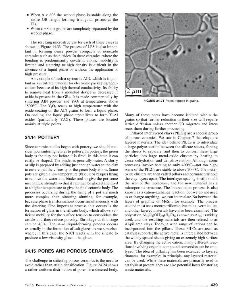
The challenge in sintering porous ceramics is the need to avoid rather than attain densification. Figure 24.24 shows a rather uniform distribution of pores in a sintered body.
Many of these pores have become isolated within the grains so that further reduction in their size will require lattice diffusion unless another GB migrates and inter-sects them during further processing.
Pillared interlayered clays (PILCs) are a special group of porous ceramics. We saw in Chapter 7 that clays are layered materials. The idea behind PILCs is to intercalate a large polyoxocation between the silicate sheets, forcing the sheets to separate, and then to convert these large particles into large metal-oxide clusters by heating to cause dehydration and dehydroxylation. Although some processes involve heating to only 400°C—not too high, some of the PILCs are stable to above 700°C. The metal-oxide clusters are then called pillars and permanently hold the clay layers apart. The interlayer spacing is still small, the size of the molecules, and the new material has a microporous structure. The intercalation process is also known as a cation-exchange reaction, but we do not need to exchange anything; we can intercalate Na between the layers of graphite or MoSi2, for example. The process studied most uses montmorillonite, but mica, vermiculite, and other layered materials have also been examined. The polycation Al13O4(OH)24(H2O)12 (known as Al13) is widely used, and the resulting materials are then refered to as Al-pillared clays. Today, a wide range of cations can be incorporated into the pillars. These PILCs are used as catalyst supports; the active metal is intercalated between the widely spaced sheets giving an extremely high surface area. By changing the active cation, many different reac-tions involving organic-compound conversion can be cata-lyzed. The idea of pillaring has been extended to layered titanates, for example; in principle, any layered material can be used. While these materials are primarily used in catalysis at present, they are also potential hosts for storing waste materials.
FIGURE 24.24 Pores trapped in grains.
2 4 .15 Por e s a n d Porous C e r a m i c s ............................................................................................................................ 439

440 .................................................................................................................................... Si n t e r i ng a n d G r a i n G row t h
The IUPAC definition of porous describes three ranges of pore sizes: microporous (<2 nm), mesoporous (2–50 nm), and macroporous (>50 nm). In 1992 a new porous material similar in many ways to the natural zeolites and known as MCM-41 was patented; the name stands for Mobil Composition of Matter No. 41. Actually this is just one of a family of mesoporous molecular sieves known as M41S. It has a hexagonal array of mesopores giving chan-nels 1.5–10 nm in diameter amd a surface area of up to 700 m2/g. The mechanism proposed for their formation is referred to as liquid-crystal templating (LCT), which is similar to one model proposed for the formation of natural zeolites. The idea is that we start with two phases and burn out one leaving a porous medium. MCM-41 is essentially a honeycomb structure (it has hexagonal symmetry), but it could have been an ordered foam. Honeycombs and foams are two forms of cellular ceramics.
We can also make porous (cellular) ceramics by simply adding air to the green body before firing; this is exactly how nature produces pumice of course, except the green body is molten glass. By analogy with pumice, a simple route is to add pores to a slurry. This is essentially the route taken to make MCM-41; such materials may be referred to as reticulated ceramics—the result of a replica-tion process. A completely different approach is to foam a liquid that contains the ceramic precursor (the approach used by nature to form pumice). We can use mechanical agitation, bubbling gas through the liquid, or generating the gas in the liquid. An example of a structure produced by this method is shown in Figure 24.25. (Compare this to the pores in Chapter 15.)
24.16 SINTERING WITH TWO AND THREE PHASES
What is new? There are two situations: (1) reactions occur between the components and (2) no reaction occurs. You can see from the schematic in Figure 24.26 that this is related to the tiling problem. In a 2D cross-sectional view
of a two-phase structure, you must see both GBs and phase boundaries (PBs). In Figure 24.26a we have two phases. If the GBs in phase B move, we can generate a microstruc-ture of isolation grains of phase A inside a single-crystal matrix of phase B. (Phase A could, for example, be poros-ity.) A three-phase system could, in principle, contain only PBs with no GBs (or the GBs could disappear by “local” grain growth inside that particular phase). The grains of the three phases shown here cannot grow unless we have diffusion of material A along the interface between phases B and C, for example. As was the case for Figure 24.16, the situation in 3D will be more complex with more con-nections and the likelihood of percolation phenomena.
Two images of a two-phase material are shown in Figure 24.27: the material is ZTA 30% (zirconia-tough-ened alumina with 30 vol% YSZ, which itself contains 10 molar% yttria). The smaller grains are in the as-sintered material; the larger grains are after heat treating at 1600°C for 30 hours. In both cases, the microstructure closely resembles Figure 24.26a, showing that the phases remain dispersed after a long anneal. You can imagine the three-phase situation if we add a nonreaction metal (e.g., Nb) to the two oxide phases. The result would be a cermet (ceramic/metal composite), a type of composite material
FIGURE 24.25 Porous ceramic.
(A)
(B)
FIGURE 24.26 Schematics of multiphase ceramics; (a) two phases and (b) three phases.

widely used in different compositions. You can see how the materials can quickly become complicated. The only requirement is that the different phases are not reacting. One phase could be a glass (or even a polymer), in which case we need not worry about GBs in that phase.
24.17 EXAMPLES OF SINTERING IN ACTION
Some of these examples are discussed in detail elsewhere in the text. Here we are concerned with why the sintering process is used.
Why do we use translucent polycrystalline alumina rather than single-crystal alumina, which is transparent, in alumina lamp envelops? Why use alumina and not yttria for this application: the yttria would allow the lamp to operate at higher temperatures producing a whiter light? The answer in both cases is the cost; both would be tech-nologically possible. The alumina envelope is particularly interesting because of the use of MgO to limit grain growth.
Templated growth of materials like BaTiO3 presents an attractive route to producing a textured ceramic. Tem-plated grain growth of alumina was discussed above. The principle involved here is the use of a seed to initiate exag-gerated grain growth.
Nanomaterials are very reactive, which means that we can usually sinter nanoparticles at temperatures that are
(A)
(B)
FIGURE 24.27 Two-phase ceramics. (a) As sintered and (b) heat treated at 1600°C for 30 hours. ZTA 30% (zirconia-toughened alumina with 30 vol% YSZ containing 10 molar% yttria).
much lower than for conventional powders. However, they are also reactive even when you do not want them to be. In this case we can coat the nanoparticles to induce a repulsion or simply to physically prevent them from joining.
Materials are bonded together during packaging in IC fabrication using several different technologies, such as anodic bonding, Si-fusion bonding, surface-activated bonding, and intermediate thin-film bonding. In each scheme, heat is applied to sinter two surfaces together. Diffusion bonding of Si wafers may require very little diffusion if the wafers are nearly atomically flat. We can improve the bonding by applying a voltage; this is the anodic bonding process and is used to join Si to SiO2.
Millefiore paperweights are essentially formed using sintering. The individual canes of glass are bonded together in a glass matrix: the essential point is that the canes do not melt.
24.18 COMPUTER MODELING
Sintering can be modeled in many different ways. One particularly interesting approach is to use Surface Evolver to model how the shape of spheres will change when they are placed in contact. In the calculation, which can in principle be extended to many more contacting spheres, the surface is allowed to move with a velocity that depends on the local curvature of the surface. At this time, the model assumes isotropic surface energies and sintering occurs by an evaporation/condensation mechanism. The approach is illustrated in Figure 24.28a, which shows two spheres that have started to sinter together. The surface of the sphere on the right is represented as a triangular mesh; the triangles are essentially small facets of a particular surface orientation. The total surface area determines the surface energy, since it is isotropic. Surface Evolver lets the surface change toward a minimum value under some constrained conditions and a grain boundary, with energy proportional to its area, is included in the calculation. The gradient of the energy is a force that is then converted to give the velocity of the interface. The motion of the surface is some multiple of the velocity; this scale factor can then be regarded as the time step, which is used in determining the dynamics of motion. The GB energy and the surface energy are related in the usual way through Young’s equa-tion so that the calculation can be run for different GB-to-surface energy ratios, which influences the development of the neck geometry as shown in Figure 24.28b.
Many other aspects of sintering are now becoming amenable to computer modeling and a new understanding of the relative importance of the different stages of sinter-ing and the different diffusion parameters will become more widely available in the near future. Indeed, most sintering models come from what has been termed the pre- “computer-simulation age.” New models are already relating these different processes at the different stages.
2 4 .18 C om p u t e r Mod e l i ng .......................................................................................................................................... 441

442 .................................................................................................................................... Si n t e r i ng a n d G r a i n G row t h
CHAPTER SUMMARYThe fundamental feature of the sintering process is the joining together of two particles without either of them melting. This process can take place fully in the solid state, although there may be a liquid involved as in the case of LPS. In fact, liquids in the form of a binder are common in commercial processes. In practice, the process may be even more complex because phase transformations may occur at the same time as sintering, and there may be more than one phase present. A full understanding of sintering makes use of everything we learned about GBs, grain growth, diffusion, and second phases in the form of pores. Computer modeling is beginning to be applied to sintering and should become more commonplace in the future.
PEOPLE IN HISTORYCoble, Robert (Bob) L. (1928–1992) was best known for showing that small additions of MgO made it possible
to form polycrystalline translucent alumina (Lucalox). This occurred while he was at the General Electric Research Laboratory in Schenectady, New York. He joined MIT in 1960. [More about this appears in the special alumina issue of J. Am. Ceram. Soc. 77(2), 1994.] He is also known for Coble creep.
Kingery, W. David (1926–2000) was awarded the Kyoto Prize in 1999. David Kingery put the science into ceramic science for two generations of ceramicists. His books, including those exploring the link between the (really) old ceramics and the new, are always worth studying.
GENERAL READINGExner, H.E. (1979) Principles of Single-Phase Sintering, in Reviews on Powder Metallurgy and Physical
Ceramics 1, 1–251. Freund Pub. House, Tel-Aviv, Israel. Not just ceramics; a very useful review.German, R.M. (1996) Sintering Theory and Practice, Wiley, New York. The standard reference. Not only
concerned with ceramics.Kang, S.-L.L. (2005) Sintering: Densifi cation, Grain Growth and Microstructure, Elsevier, Oxford. Very
readable.Kuczynski, G.C. et al. (Eds.) Sintering Processes, Materials Science Research; Plenum Press (now Springer),
New York. Another series of Proceedings from the 1960s and 1970s. More classic discussions.Microporous and Mesoporous Materials. This journal is a source for current research. Sintering and Related
Phenomena. Proceedings from the 1960s and 1970s. Many classic discussions.
SPECIFIC REFERENCESAshby, M.F. (1974) “A first report on sintering diagrams,” Acta Met. 22, 275.Casellas, D., Nagl, M.M., Llanes, L., and Anglada, M. (2005) “Microstructural coarsening of zirconia-
toughened alumina composites,” J. Am. Ceram. Soc. 88(7), 1958.Clay and Clay Minerals. The journal of The Clay Minerals Society.
(A)
(B)
FIGURE 24.28 (a, b) Modeling sintering using Surface Evolver.

Gil, A., Gandía, L., and Vicente, M. (2000) “Recent advances in the synthesis and catalitic applications of pillared clays,” Catal. Rev-Sci. Eng. 42(1&2), 145. A comprehensive review.
Green, D.J. and Colombo, P. (2003) “Cellular ceramics: intriguing structures, novel properties, and innovative applications,” MRS Bull. (April), 296.
Kingery, W.D. (1959). “Densification during sintering in the presence of a liquid phase 1. theory,” J. Appl. Phys. 30, 301. The LPS paper.
Maximemko, A.L. and Olevsky, E.A. (2004) “Effective diffusion coeffi cients in solid-state sintering,” Acta Mater. 52, 2953. An example of the use of computer modeling to analyze the role of different diffusion processes in the various stages of sintering.
Mortensen, A., (1997) “Kinetics of densifi cation by solution-reprecipitation,” Acta Mater. 45, 749. Quite recent update to the classic studies of LPS by Kingery.
Swinkels, F.B. and Ashby, M.F. (1981) “A second report on sintering diagrams,” Acta Met. 29, 259.Tikare, V. and Cawley, J.D. (1998) “Numerical simulation of grain growth in liquid phase sintered materials-I.
model,” Acta Mater. 46, 1333.Wakai, F. and Aldinger, F. (2003) “Sintering through surface motion by the difference in mean curvature,”
Acta Mater. 51, 4013. Uses Surface Evolver to examine sintering.Zhou, Y. and Rahaman, M.N. (1997) “Effect of redox reaction on the sintering behavior of cerium oxide,”
Acta Mater. 45, 3635. Sintering CeO2 as Ce4+ is reduced to Ce3+.Zuo, R. and Rödel, J. (2004) “Temperature dependence of constitutive behavior for solid-state sintering of
alumina,” Acta Mater. 52, 3059. Includes a discussion of hot-forging of alumina.
EXERCISES24.1 You have sintered your ceramic at 1800°C for 12 hours and attained 95% theoretical density. You then con-
tinue to heat treat it for another 12 hours at the same temperature but detect no change in density. Could the grain size of the material have changed?
24.2 You have two 1 μm-diameter spheres of amorphous Si and two similar spheres of crystalline Si. You bring the two pairs of spheres into contact without any applied pressure and heat for 1 hour at 1000°C. Discuss all the differences you will find when comparing the two pairs of dumbbells.
24.3 You place two spheres of crystalline MgO in contact without applying pressure. You find that each sphere experiences a stress due to contact with the other. Why is this so?
24.4 A sample consists of two slabs of TiO2 separated by a 100 nm film of silica. The sample is heated to 1500°C. What do you expect to occur? How would you make use of information on the Hamacker constant in discuss-ing this material?
24.5 A translucent alumina is prepared commercially by adding up to 200 ppm of MgO before sintering at 1800°C. This addition allows the alumina to be sintered to full density. Summarize the possible reasons for this effect and suggest an alternative additive.
24.6 What would be the advantages and disadvantages of making Na-vapor lamp envelopes using yttria instead of alumina?
24.7 You are given batches of powder of LiF, NaCl, and KCl; each has a grain size (grain diameter) of 100 nm. You cold isostatic press (CIP) each sample to 95% density and then sinter each at 1100°C. After 5 hours you remeasure the percent density. What results do you expect to see?
24.8 A glass contains pores that are 1 μm in diameter and are filled with N2 at 0.8 atm pressure. If the surface tension of the glass is 28 Pa and the relative density is 0.85, what will the pore size be when the gas pressure just balances the pressure due to the surface tension? Repeat this calculation for pores that are 0.1 μm and 10 μm in diameter and discuss the changes.
24.9 In a sample of MgO held at 1500°C grains of MgO grew from 1 μm diameter to 10 μm diameter in 1 hour. If the grain boundary diffusion energy is 250 kJ/mol, what will the grain size be after 2 hours and 4 hours? If the experiment were repeated at 1600°C, how would these results change?
24.10 Imagine making a close-packed material by filling a container with 20-μm-diameter glass spheres. You then heat this “material” for 12 × 103 seconds at 650°C and the “material” shrinks by 5 vol%. You take an identical sample and find that the same shrinkage is achieved in 360 seconds at 700°C. Assuming that the surface energy of the glass is 0.3 J/m2, calculate the viscosity of the glass at each temperature and deduce an activa-tion energy.
C h a p t e r Su m m a ry .......................................................................................................................................................... 443