single family & duplex residential
TRANSCRIPT

Permit Center 210 Lottie Street, Bellingham, WA 98225
Phone: (360) 778-8300 Fax: (360) 778-8301 TTY: (360) 778-8382 Email: [email protected] Web: www.cob.org/permits
BSD#063 – 4/17/2020
Single Family & Duplex Residential Permit Application Requirements
Use the table below to determine submittal requirements for your application based on the scope of work proposed:
One (1) complete PDF version of plans, supplemental documents shall be submitted in
PDF format and saved as individually-named PDF files separate from the drawing files
via email, a CD, flash drive or an FTP website:
Please see the Electronic Submittal Requirements handout for more information.
For additions or remodels to create an Accessory Dwelling Unit (ADU), see the ADU handout and discuss your project with Permit Center staff prior to application.
Project Type
New
Sin
gle
F
am
ily
Resid
en
ce,
Du
ple
x,
Ad
dit
ion
or
Mo
ved
H
ou
se
Inte
rio
r R
em
od
el
Fo
un
dati
on
O
nly
New
G
ara
ge,
Carp
ort
or
Acce
sso
ry
Bu
ild
ing
Over-
Heig
ht
Fen
ce o
r R
eta
inin
g
Wall
Deck
s,
Dem
oliti
on
o
r M
an
uf.
H
om
e
Submittal Requirements
FO
RM
S
Building Permit Application Form
SE
E S
EP
AR
AT
E H
AN
DO
UT
S
Fixture Count, as applicable
Energy Code Compliance Worksheets
(if heated)
Includes 1) Prescriptive Method (or Component Performance), 2) Glazing Schedule & 3) Heating System Sizing Calculator. Forms are available online at: http://energy.wsu.edu/BuildingEfficiency/EnergyCode.aspx. Structural Calculations, as applicable
(including pole buildings)
CO
NS
TR
UC
TIO
N D
RA
WIN
GS
Site Plan
Foundation Plan
Floor Plan
Key Plan
Framing Plans
Floor Framing
Elevations
If height increases
Cross Section(s)
Detail(s), as required
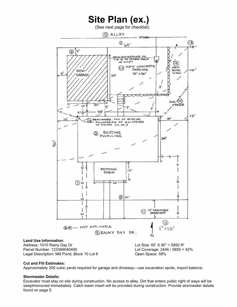
Site Plan (ex.) (See next page for checklist)
Land Use Information: Address: 1010 Rainy Day Dr Lot Size: 65’ X 90” = 5850 ft2 Parcel Number: 123369040400 Lot Coverage: 2446 / 5850 = 42% Legal Description: Mill Pond, Block 10 Lot 6 Open Space: 58%
Cut and Fill Estimates: Approximately 200 cubic yards required for garage and driveway—use excavation spoils, import balance. Stormwater Details: Excavator must stay on site during construction. No access to alley. Dirt that enters public right of ways will be swept/removed immediately. Catch basin insert will be provided during construction. Provide stormwater details found on page 5.
Site Plan Checklist (see previous page for example)
Whenever a site plan is required, the following items shall always be provided:
□ Property Information: Include the address(es), parcel size & parcel number or legal description
□ Scale: Label the drawing scale (minimum 1”=20’)
□ A North Arrow
□ Property Lines: Including dimensions of the project site.
□ Structures: Identify new vs. existing structures, and/or show area of work. Include the location of and distances
between all existing and proposed structures.
□ Setbacks: Show distances from all property lines to all proposed and existing buildings.
□ Streets/Right-of-ways: Label the right-of-way and street names and locations for all streets from which the lot is
accessed and adjacent.
□ Utilities: Show the location of all existing and proposed public and on-site utility structures and lines, such as water,
sewer and stormwater lines or on-site stormwater facilities or septic systems.
□ Special Locations: Please note if property is within special land-use areas such as, but not limited to, the Lake
Whatcom Watershed, an Urban Village, Cordata Design Review or a FEMA flood zone. Additional info may be required
□ Show on plans and number parking, include surface material and dimensions of spaces
When the work is new construction, an addition or includes any land disturbance, the following items shall be provided
in addition to the above items:
□ Location of critical areas or buffers, both on-site and on adjacent properties, including, but not limited to, shorelines,
wetlands, streams, steep slopes, flood zones and habitats
□ Landscaping Plan: For duplexes, or if the project site is within a shoreline designation or has critical areas on-site, all
existing vegetation proposed to remain and all proposed landscaping, including location and type. □ Stormwater Information (see additional info on next page)
300 – 2,000 ft2 new and/or replaced hard surface:
□ Show location of construction entrance and silt fence
□ Construction entrance and silt fence detail drawings
□ Construction Stormwater Pollution Prevention Plan (SWPPP)
□ Hard surface area calculation table
□ If under 2000 sq ft of hard surface AND a new SFR or duplex:
o Show on-site stormwater management BMPs (e.g. infiltration trench, dispersion trench or perforated stub
out)
o Detail drawing and installation guidelines for the selected on-site BMP
> 2,000 ft2 - < 5,000 ft2 new and/or replaced hard surface
□ All Level-1 requirements above
□ Show on-site stormwater management BMP locations and details (e.g. infiltration trench, dispersion trench or
perforated stub out), or connection to storm system if onsite management is infeasible
□ 13-element Stormwater Pollution Prevention Plan (SWPPP)
□ Show BMP T 5.13 Soil Amendment detail.
□ A soils report as outlined in the stormwater submittal guidelines
>5,000 ft2 of new and/or replaced hard surface
□ Drainage Report
□ Hydrological modeling files
□ Hard surface area calculation table
□ Signed civil plans
□ Easements: Show the location of all existing and proposed easements.
□ Access: Existing and proposed vehicular access to the site, including the size and location of driveways and curb cuts.
□ Topography: Show five-foot contour lines showing existing and proposed grades. If lot is flat, label lot as “flat lot”.
□ Cut & Fill: Indicate total cubic yards of material to be imported to or exported from site.
□ Other Structures: Show the location of proposed and existing retaining walls, rockeries and fences.
□ Elevation Benchmark: Show location, description and elevation of permanent benchmark for measuring height of
building.
For duplexes, the following items shall be provided in addition to the above items:
□ Lot Coverage (the building footprint): List the allowed maximum (35%) and the proposed coverage.
□ Open Space (area of pervious ground surface remaining after development): List the minimum required (25%) and the proposed
open space.
□ Usable Space: List the minimum required (250 sq. ft. per unit) and proposed amounts of usable space. □ Optional Development Regulations (See planning staff for an explanation of available options): Describe options, setbacks and/or
lot coverage used, if any.
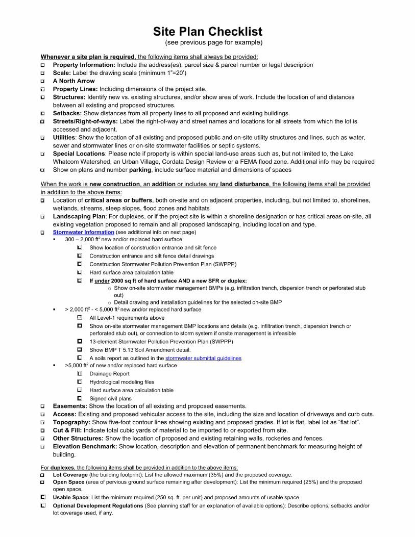
Stormwater Management Details
Hard Surface Area Table
Hard surface area (sq ft)
Existing Proposed
New Replaced
Home Garage
Other structures (sheds, porches,
decks, patios, etc)
Concrete/Asphalt Gravel
Pervious Pavement Driveway/Road
Other Total(s)
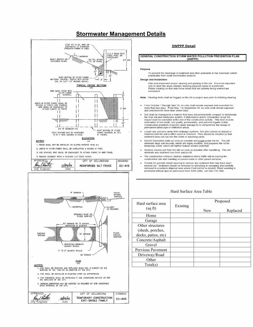
Foundation Plan (ex.) (See next page for checklist)
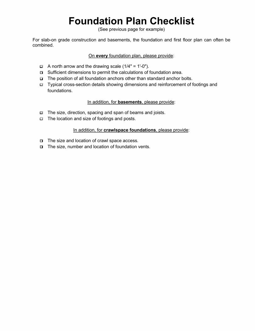
Foundation Plan Checklist (See previous page for example)
For slab-on grade construction and basements, the foundation and first floor plan can often be combined.
On every foundation plan, please provide:
□ A north arrow and the drawing scale (1/4" = 1'-0").
□ Sufficient dimensions to permit the calculations of foundation area.
□ The position of all foundation anchors other than standard anchor bolts.
□ Typical cross-section details showing dimensions and reinforcement of footings and
foundations.
In addition, for basements, please provide:
□ The size, direction, spacing and span of beams and joists.
□ The location and size of footings and posts.
In addition, for crawlspace foundations, please provide:
□ The size and location of crawl space access.
□ The size, number and location of foundation vents.
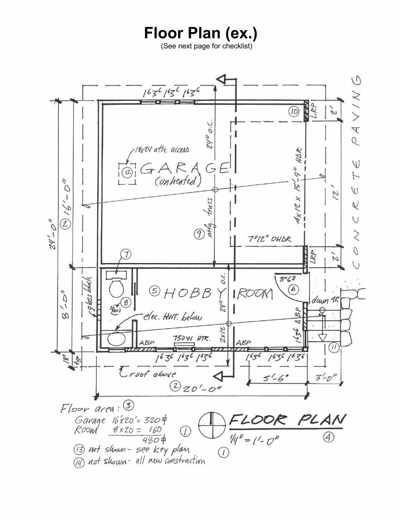
Floor Plan (ex.) (See next page for checklist)
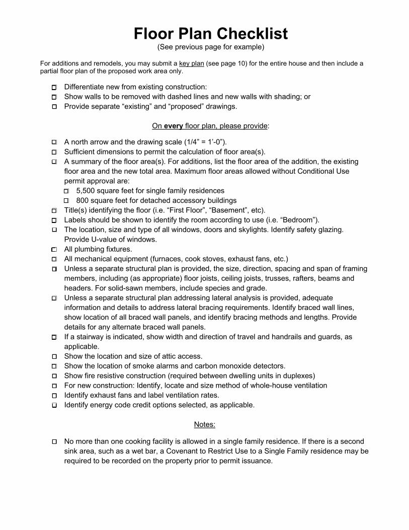
Floor Plan Checklist (See previous page for example)
For additions and remodels, you may submit a key plan (see page 10) for the entire house and then include a partial floor plan of the proposed work area only.
□ Differentiate new from existing construction:
□ Show walls to be removed with dashed lines and new walls with shading; or
□ Provide separate “existing” and “proposed” drawings.
On every floor plan, please provide:
□ A north arrow and the drawing scale (1/4” = 1’-0”).
□ Sufficient dimensions to permit the calculation of floor area(s).
□ A summary of the floor area(s). For additions, list the floor area of the addition, the existing
floor area and the new total area. Maximum floor areas allowed without Conditional Use
permit approval are:
□ 5,500 square feet for single family residences
□ 800 square feet for detached accessory buildings
□ Title(s) identifying the floor (i.e. “First Floor”, “Basement”, etc).
□ Labels should be shown to identify the room according to use (i.e. “Bedroom”).
□ The location, size and type of all windows, doors and skylights. Identify safety glazing.
Provide U-value of windows.
□ All plumbing fixtures.
□ All mechanical equipment (furnaces, cook stoves, exhaust fans, etc.)
□ Unless a separate structural plan is provided, the size, direction, spacing and span of framing
members, including (as appropriate) floor joists, ceiling joists, trusses, rafters, beams and
headers. For solid-sawn members, include species and grade.
□ Unless a separate structural plan addressing lateral analysis is provided, adequate
information and details to address lateral bracing requirements. Identify braced wall lines,
show location of all braced wall panels, and identify bracing methods and lengths. Provide
details for any alternate braced wall panels.
□ If a stairway is indicated, show width and direction of travel and handrails and guards, as
applicable.
□ Show the location and size of attic access.
□ Show the location of smoke alarms and carbon monoxide detectors.
□ Show fire resistive construction (required between dwelling units in duplexes)
□ For new construction: Identify, locate and size method of whole-house ventilation
□ Identify exhaust fans and label ventilation rates.
□ Identify energy code credit options selected, as applicable.
Notes:
□ No more than one cooking facility is allowed in a single family residence. If there is a second
sink area, such as a wet bar, a Covenant to Restrict Use to a Single Family residence may be
required to be recorded on the property prior to permit issuance.
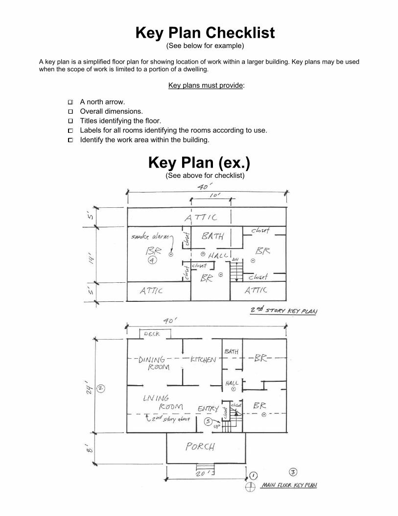
Key Plan Checklist (See below for example)
A key plan is a simplified floor plan for showing location of work within a larger building. Key plans may be used when the scope of work is limited to a portion of a dwelling.
Key plans must provide:
□ A north arrow.
□ Overall dimensions.
□ Titles identifying the floor.
□ Labels for all rooms identifying the rooms according to use.
□ Identify the work area within the building.
Key Plan (ex.) (See above for checklist)
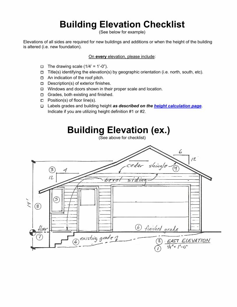
Building Elevation Checklist (See below for example)
Elevations of all sides are required for new buildings and additions or when the height of the building is altered (i.e. new foundation).
On every elevation, please include:
□ The drawing scale (1/4’ = 1’-0”).
□ Title(s) identifying the elevation(s) by geographic orientation (i.e. north, south, etc).
□ An indication of the roof pitch.
□ Description(s) of exterior finishes.
□ Windows and doors shown in their proper scale and location.
□ Grades, both existing and finished.
□ Position(s) of floor line(s).
□ Labels grades and building height as described on the height calculation page.
Indicate if you are utilizing height definition #1 or #2.
Building Elevation (ex.) (See above for checklist)
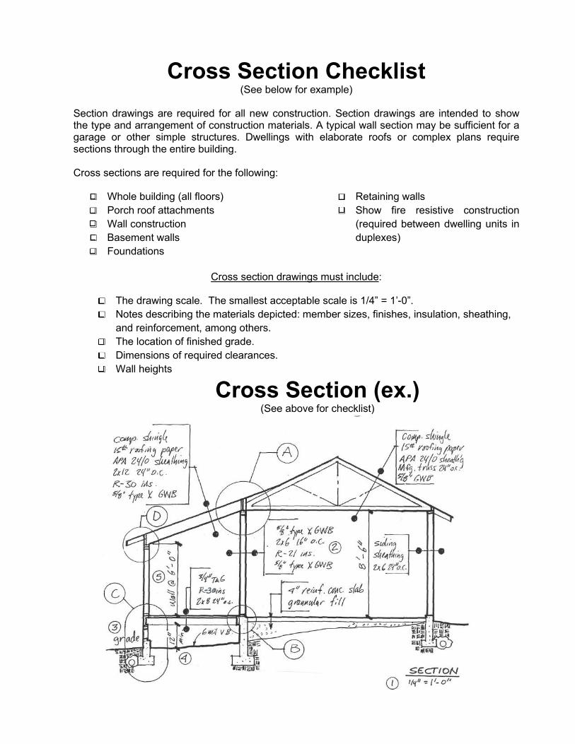
Cross Section Checklist (See below for example)
Section drawings are required for all new construction. Section drawings are intended to show the type and arrangement of construction materials. A typical wall section may be sufficient for a garage or other simple structures. Dwellings with elaborate roofs or complex plans require sections through the entire building. Cross sections are required for the following:
□ Whole building (all floors)
□ Porch roof attachments
□ Wall construction
□ Basement walls
□ Foundations
□ Retaining walls
□ Show fire resistive construction
(required between dwelling units in
duplexes)
Cross section drawings must include:
□ The drawing scale. The smallest acceptable scale is 1/4” = 1’-0”.
□ Notes describing the materials depicted: member sizes, finishes, insulation, sheathing,
and reinforcement, among others.
□ The location of finished grade.
□ Dimensions of required clearances.
□ Wall heights
Cross Section (ex.) (See above for checklist)
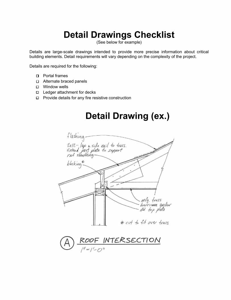
Detail Drawings Checklist (See below for example)
Details are large-scale drawings intended to provide more precise information about critical building elements. Detail requirements will vary depending on the complexity of the project. Details are required for the following:
□ Portal frames
□ Alternate braced panels
□ Window wells
□ Ledger attachment for decks
□ Provide details for any fire resistive construction
Detail Drawing (ex.)
9/29/17
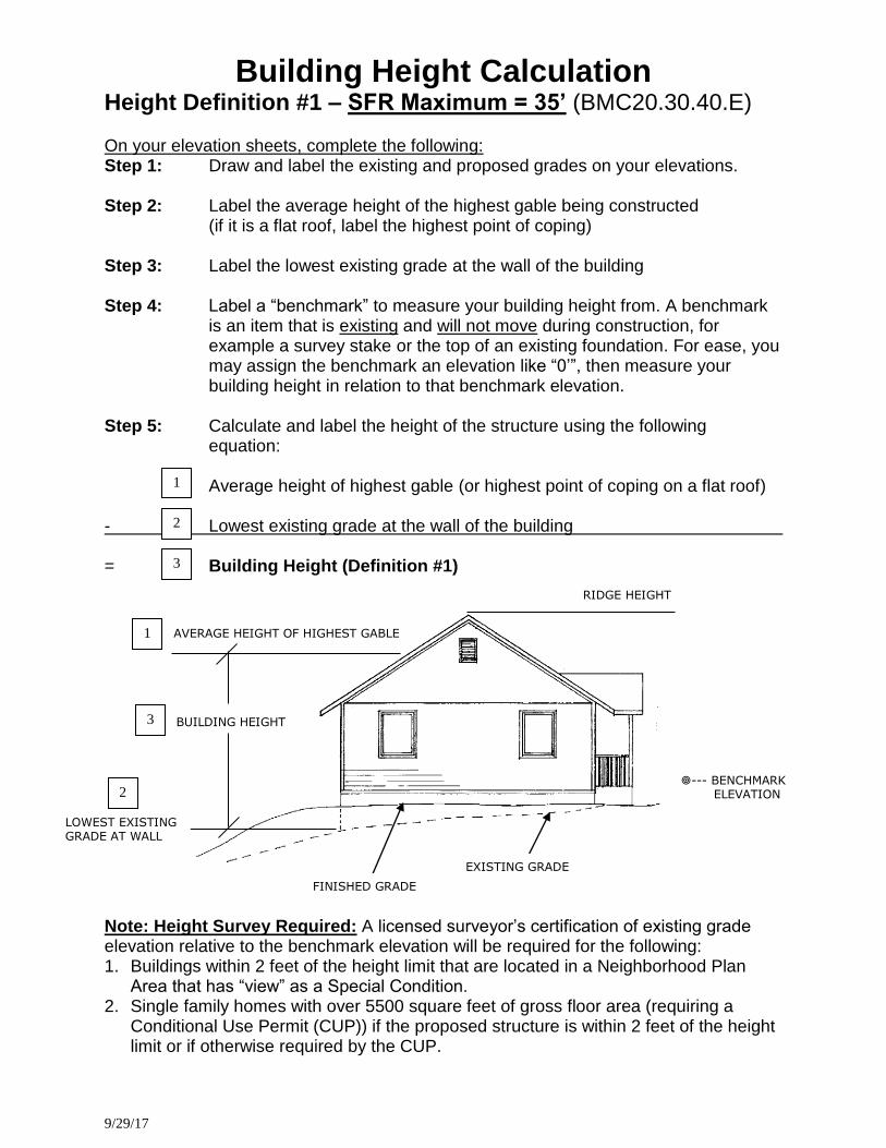
Building Height Calculation Height Definition #1 – SFR Maximum = 35’ (BMC20.30.40.E) On your elevation sheets, complete the following: Step 1: Draw and label the existing and proposed grades on your elevations. Step 2: Label the average height of the highest gable being constructed
(if it is a flat roof, label the highest point of coping)
Step 3: Label the lowest existing grade at the wall of the building
Step 4: Label a “benchmark” to measure your building height from. A benchmark is an item that is existing and will not move during construction, for example a survey stake or the top of an existing foundation. For ease, you may assign the benchmark an elevation like “0’”, then measure your building height in relation to that benchmark elevation.
Step 5: Calculate and label the height of the structure using the following
equation:
Average height of highest gable (or highest point of coping on a flat roof) - Lowest existing grade at the wall of the building
= Building Height (Definition #1)
Note: Height Survey Required: A licensed surveyor’s certification of existing grade elevation relative to the benchmark elevation will be required for the following: 1. Buildings within 2 feet of the height limit that are located in a Neighborhood Plan
Area that has “view” as a Special Condition. 2. Single family homes with over 5500 square feet of gross floor area (requiring a
Conditional Use Permit (CUP)) if the proposed structure is within 2 feet of the height limit or if otherwise required by the CUP.
1
.
3
.
2
.
1
.
2
.
3
.
AVERAGE HEIGHT OF HIGHEST GABLE
BUILDING HEIGHT
LOWEST EXISTING GRADE AT WALL
--- BENCHMARK ELEVATION
RIDGE HEIGHT
FINISHED GRADE
EXISTING GRADE
9/29/17
BUILDING HEIGHT
BENCHMARK ELEVATION
3
.
AVERAGE HEIGHT OF HIGHEST GABLE
RIDGE HEIGHT
1
.
EXISTING GRADE
2
. HIGHEST EXISTING GRADE WITHIN 20’ OF BUILDING
20’ FINISHED GRADE
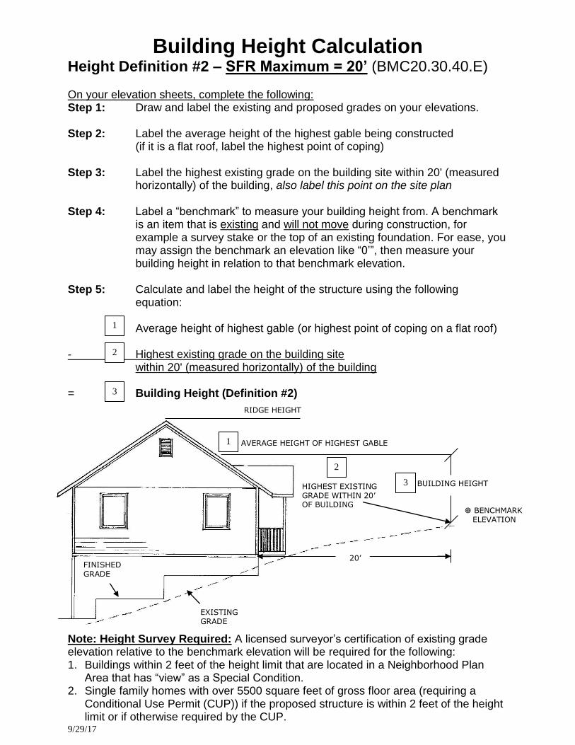
Building Height Calculation Height Definition #2 – SFR Maximum = 20’ (BMC20.30.40.E) On your elevation sheets, complete the following: Step 1: Draw and label the existing and proposed grades on your elevations. Step 2: Label the average height of the highest gable being constructed
(if it is a flat roof, label the highest point of coping)
Step 3: Label the highest existing grade on the building site within 20' (measured horizontally) of the building, also label this point on the site plan
Step 4: Label a “benchmark” to measure your building height from. A benchmark
is an item that is existing and will not move during construction, for example a survey stake or the top of an existing foundation. For ease, you may assign the benchmark an elevation like “0’”, then measure your building height in relation to that benchmark elevation.
Step 5: Calculate and label the height of the structure using the following
equation:
Average height of highest gable (or highest point of coping on a flat roof) - Highest existing grade on the building site
within 20' (measured horizontally) of the building
= Building Height (Definition #2)
Note: Height Survey Required: A licensed surveyor’s certification of existing grade elevation relative to the benchmark elevation will be required for the following: 1. Buildings within 2 feet of the height limit that are located in a Neighborhood Plan
Area that has “view” as a Special Condition. 2. Single family homes with over 5500 square feet of gross floor area (requiring a
Conditional Use Permit (CUP)) if the proposed structure is within 2 feet of the height limit or if otherwise required by the CUP.
1
.
3
.
2
.
BSD#001 – 9/27/2017
Permit Center 210 Lottie Street, Bellingham, WA 98225
Phone: (360) 778-8300 Fax: (360) 778-8301 TTY: (360) 778-8382 Email: [email protected] Web: www.cob.org/permits
Site Address
Parcel Number
Legal Description Rental Property? Yes No If Yes, please register here: http://www.cob.org/services/housing/rentals
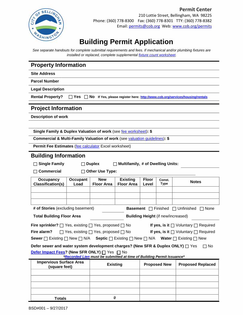
Project Information Description of work
Single Family & Duplex Valuation of work (see fee worksheet): $
Commercial & Multi-Family Valuation of work (see valuation guidelines): $
Permit Fee Estimates (fee calculator Excel worksheet)
Building Information
Single Family Duplex Multifamily, # of Dwelling Units:
Commercial Other Use Type:
Occupancy Classification(s)
Occupant Load
New Floor Area
Existing Floor Area
Floor Level
Const. Type Notes
# of Stories (excluding basement) Basement Finished Unfinished None
Total Building Floor Area Building Height (if new/increased)
Fire sprinkler? Yes, existing Yes, proposed No If yes, is it Voluntary Required Fire alarm? Yes, existing Yes, proposed No If yes, is it Voluntary Required Sewer Existing New N/A Septic Existing New N/A Water Existing New
Defer sewer and water system development charges? (New SFR & Duplex ONLY) Yes No Defer Impact Fees? (New SFR ONLY) Yes No
*Recorded Lien must be submitted at time of Building Permit Issuance* Impervious Surface Area
(square feet) Existing Proposed New Proposed Replaced
Totals
Property Information
installed or replaced, complete supplemental fixture count worksheet.See separate handouts for complete submittal requirements and fees. If mechanical and/or plumbing fixtures are
Building Permit Application

Site Address _____________________________________Permit Number________________________
*I am the owner of the property described above or am authorized by the owner to sign and submit this application. I certify underpenalty of perjury of the laws of the State of Washington that the information on this application and all information submittedherewith is true, complete and correct. I also acknowledge that by signing the application I am the responsible party to receive allcorrespondence from the City regarding this project including, but not limited to, expiration notifications. If I, at any point during thereview or inspection process, am no longer the Applicant for this project, it is my responsibility to update this information with theCity in writing in a timely manner. I understand that this form is being submitted electronically and my typed name on the signatureline will qualify as my signature for purposes of the above certification.
Signature Date Printed Name
City and State where this application is signed
People Information complete as many entries as necessary to indicate all responsible parties:owner, applicant, contractor, design professional, engineer, tenant, etc. Use additional sheets if needed.
Check all that apply Applicant* Owner Contractor Other Name Company Mailing Address City State Zip Code Phone Email
Please check here if you would like to receive email notifications called Technical Assistance Bulletins (TABs)
Check all that apply Applicant* Owner Contractor Other Name Company Mailing Address City State Zip Code Phone Email
Please check here if you would like to receive email notifications called Technical Assistance Bulletins (TABs)
Check all that apply Applicant* Owner Contractor Other Name Company Mailing Address City State Zip Code Phone Email
Please check here if you would like to receive email notifications called Technical Assistance Bulletins (TABs)
PERSON PERFORMING THE WORK is Property owner or Tenant and is exempt from contractor licensing requirements pursuant to RCW
18.27.090. If tenant is checked, an additional acknowledgment form must be completed prior to issuance. Licensed contractor, please complete licensing information below (may be deferred until issuance).
L & I License # Exp
Please note, businesses operating in the City limits must have a valid Bellingham Business Registration.
FINANCING INFORMATION required if project valuation exceeds $5,000, per RCW 19.27.095 (may be deferred until issuance) Lender administering the construction financing or firm issuing a payment bond (if any) on behalf of the prime contractor for the protection of the owner, if the bond is for an amount not less than 50% of the total amount of the construction project (if owner is self financing, please indicate) Name Day Phone Mailing Address
City State Zip Code
BSD#190 – 10/17/18
Permit Center 210 Lottie Street, Bellingham, WA 98225
Phone: (360) 778-8300 Fax: (360) 778-8301 TTY: (360) 778-8382 Email: [email protected] Web: www.cob.org/permits
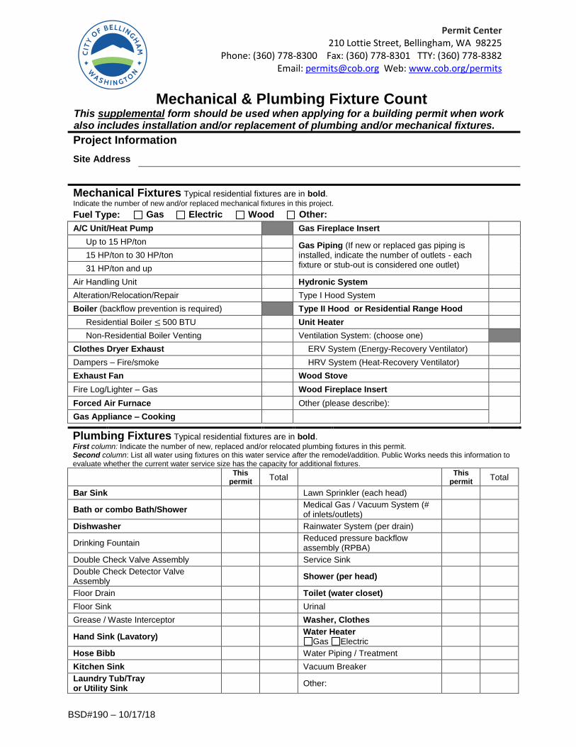
Mechanical & Plumbing Fixture Count This supplemental form should be used when applying for a building permit when work also includes installation and/or replacement of plumbing and/or mechanical fixtures.
Project Information
Site Address
Mechanical Fixtures Typical residential fixtures are in bold. Indicate the number of new and/or replaced mechanical fixtures in this project. Fuel Type: Gas Electric Wood Other:
A/C Unit/Heat Pump Gas Fireplace Insert
Up to 15 HP/ton Gas Piping (If new or replaced gas piping is installed, indicate the number of outlets - each fixture or stub-out is considered one outlet)
15 HP/ton to 30 HP/ton
31 HP/ton and up
Air Handling Unit Hydronic System
Alteration/Relocation/Repair Type I Hood System
Boiler (backflow prevention is required) Type II Hood or Residential Range Hood
Residential Boiler ≤ 500 BTU Unit Heater
Non-Residential Boiler Venting Ventilation System: (choose one)
Clothes Dryer Exhaust ERV System (Energy-Recovery Ventilator)
Dampers – Fire/smoke HRV System (Heat-Recovery Ventilator)
Exhaust Fan Wood Stove
Fire Log/Lighter – Gas Wood Fireplace Insert
Forced Air Furnace Other (please describe): Gas Appliance – Cooking
Plumbing Fixtures Typical residential fixtures are in bold. First column: Indicate the number of new, replaced and/or relocated plumbing fixtures in this permit. Second column: List all water using fixtures on this water service after the remodel/addition. Public Works needs this information to evaluate whether the current water service size has the capacity for additional fixtures.
This
permit Total
This permit
Total
Bar Sink Lawn Sprinkler (each head)
Bath or combo Bath/Shower Medical Gas / Vacuum System (# of inlets/outlets)
Dishwasher Rainwater System (per drain)
Drinking Fountain Reduced pressure backflow assembly (RPBA)
Double Check Valve Assembly Service Sink
Double Check Detector Valve Assembly
Shower (per head)
Floor Drain Toilet (water closet)
Floor Sink Urinal
Grease / Waste Interceptor Washer, Clothes
Hand Sink (Lavatory) Water Heater
Gas Electric
Hose Bibb Water Piping / Treatment
Kitchen Sink Vacuum Breaker
Laundry Tub/Tray or Utility Sink
Other: