simultaneous retrofit and heat integration of chemical processes
TRANSCRIPT
Simultaneous Retrofit and Heat Integration of Chemical Processes
Jose M. Ponce-Ortega,†,‡ Arturo Jimenez-Gutierrez,† and Ignacio E. Grossmann§
Departamento de Ingenierıa Quımica, Instituto Tecnologico de Celaya, Celaya, Guanajuato 38010, Mexico;Facultad de Quımica, UniVersidad Michoacana de San Nicolas de Hidalgo, Morelia, Michoacán 58060,Mexico; and Chemical Engineering Department, Carnegie Mellon UniVersity, Pittsburgh, PennsylVania 15213
In this paper, a new formulation for the retrofit of heat exchanger networks considering process modificationsis presented. The method accounts for the interactions between the process conditions and the heat integrationoptions to provide an optimal structure for a redesigned heat exchanger network. The formulation is based ona superstructure that considers explicitly the plant layout and the piping arrangement, which yields a mixed-integer nonlinear programming model. The model presented here includes the treatment of isothermal processstreams that exchange their latent heats, in addition to the streams commonly considered with sensible heatloads. The objective function consists of maximizing the total annual profit for the retrofit process, whichincludes the income from products sales and the expenses due to raw materials, capital cost for new units,utility costs, and the piping modification costs. The results for the cases of study show that significantimprovement in the process profitability can be obtained with the simultaneous approach presented in thiswork for process retrofit with respect to the sole consideration of the heat exchanger networks.
1. Introduction
Heat exchanger networks (HENs) have been widely appliedin industrial projects over the past decades because they providesignificant energy and economic savings. A good number ofmethodologies have been proposed for the HEN synthesisproblem; for retrofit problems, however, the available methodsare more limited, as has been noted in the review papers byFurman and Sahinidis,1 Jezowski,2,3 and Gundersen and Naess.4
The first works that considered the HEN retrofit problem werebased on the pinch method.5,6 Within this approach, an energyrecovery level is first obtained as part of a targeting procedure,and the basic rules of the pinch design method are then appliedto review the existing network.7 Polley et al.8 extended the useof the pinch method to include pressure drop considerationsfor the retrofit of the HEN. Several mathematical programmingmethods have been proposed for the retrofit of HENs. Ciric andFloudas9 presented a mixed-integer nonlinear programming(MINLP) model, which was based on the transhipment modelby Papoulias and Grossmann10 and an extension of the synthesissuperstructure by Floudas et al.,11 to model the networkconfiguration and provide the optimal structure of the revisednetwork. Yee and Grossmann12 reported a general superstructureand formulated an MINLP model that represented explicitlyexisting and potential exchangers for the retrofit problem. Maet al.13 proposed a two-step approach based on the superstructureby Yee and Grossmann.14 A methodology that combined theuse of thermodynamics and mathematical programming tech-niques was proposed by Briones and Kokossis.15 Sorsak andKravanja16 reported an MINLP model for the retrofit of HENscomprising different exchanger types. Bjork and Nordman17
proposed an MINLP model to solve large-scale HEN retrofitproblems. Two methodologies for the retrofit of HENs consider-ing the pressure drop effects were presented by Nie and Zhu18
and Lopes-Silva and Zemp.19 Athier et al.20 presented a hybridmethod based on simulating annealing and non linear program-
ming techniques. Zhu and Asante21 proposed an approach thatcombined mathematical programming with a set of heuristicrules.
Only a few works have attempted the simultaneous treatmentof process modifications as part of HEN problems. Some ideasalong these lines have been considered in the works by Duranand Grossmann,22 Lang et al.,23 and Grossmann et al.,24 in whichthe optimal flowsheet for the process is obtained by enforcingthe minimum utility target. Zhang and Zhu25 addressed theproblem of HEN retrofit considering process changes. However,these authors only considered the effects on utility consumptionand did not take into account the capital cost associated withthe retrofit process.
Most of the methods described above for HEN retrofit assumethat the process conditions (inlet and outlet temperatures, streamflow rates) are fixed, so that no interactions with processmodifications are considered (see Figure 1). Allowing forpotential adjustments in the operating conditions should providethe basis for more cost-effective heat integration. We shouldalso note that none of the methodologies reported for the HENretrofit has included the explicit treatment of isothermal streams,which are very common in the chemical industry, for instance,in the operation of distillation columns. In HEN synthesisproblems, a fairly common approach to the treatment ofisothermal streams consists in assuming a one degree changewith a suitable adjustment of a pseudoheat capacity value toequal the enthalpy change. This approach, however, is proneto scaling problems during the problem numerical solution.Recent works have shown a more formal treatment of isothermalstreams for HEN synthesis problems.26,27
In this paper, an MINLP model for the HEN retrofit thatconsiders simultaneously the HEN structure and process modi-fications is presented. The proposed model considers the plantlayout and modification costs through the superstructure by Yeeand Grossmann12 in which operational and structural modifica-tions of the process are added and considered simultaneously.In addition, the model considers explicitly the utility and thecapital cost of the units and takes into account the isothermalprocess streams that may appear in the process using theapproach reported by Ponce-Ortega et al.26
† Instituto Tecnologico de Celaya.‡ Universidad Michoacana de San Nicolas de Hidalgo.§ Carnegie Mellon University.
Ind. Eng. Chem. Res. 2008, 47, 5512–55285512
10.1021/ie071182+ CCC: $40.75 2008 American Chemical SocietyPublished on Web 07/30/2008

2. Outline
For a proper retrofit analysis that incorporates the operatingconditions of the process, it is necessary to consider the plantlayout. Therefore, this work uses a two-dimensional superstruc-ture for the HEN retrofit model in which the hot and cold processstreams are identified in the retrofit process as part of the processconditions (see Figure 2).
Figure 3 shows the superstructure for the HEN retrofit fortwo hot and two cold process streams based on the originalformulation by Yee and Grossmann12 where one can see thecomplexity of the potential interconnections. Exchangers 1, 2,and 3 exist in the original network, whereas exchanger 4 is anew unit that may or may not exist in the optimal networkconfiguration. The two-dimensional layout of the piping isexplicitly taken into account in the superstructure, such that allpossible interconnections between process streams and exchang-ers are considered. As a consequence, the model allows throughrepiping the reassignment of existing exchangers to differentstreams to maximize the use of existing area and exchangers.Also, additional area to existing exchangers is considered as aretrofit option.
3. Model Formulation
The proposed mathematical formulation applies to thegeneralization of the superstructure of Figure 3 for arbitrarynumber of process streams, existing exchangers and potentialnew exchangers. Rules to establish the number of potential newexchangers are given in Yee and Grossmann.12 The following
sets are used for the model development. HPS1 contains thehot process streams that exchange sensible heat in the network,HPS2 contains the hot process isothermal streams (i.e., theyexchange only latent heat and their temperatures remainconstant), HPS contains all the hot process streams (HPS )HPS1∪HPS2), HU corresponds to the hot utility streams andHS contains all the hot streams (HS ) HPS∪HU). HS1 is a setthat contains the hot streams excluding isothermal streams (HS1) HPS1∪HU). Similarly, CPS1 is the set for the cold processstreams that exchange sensible heat and CPS2 includes the coldprocess isothermal streams, whereas CPS, CU and CS representthe total cold process streams (CPS ) CPS1∪CPS2), the coldutility stream, and all the cold streams (CS ) CPS∪CU),respectively. CS1 contains the cold nonisothermal streams (CS1) CPS1∪CU). HCPS contains the hot and cold process streams(HCPS ) HPS∪CPS), and the set HCTS contains all hot andcold process and utility streams (HCTS ) HS∪CS). The set Erepresents all the exchangers in the superstructure, whereas thesets EE and NE represent the existing and the new exchangers,respectively. The detailed description of the symbols used inthe model formulation is given in the Nomenclature section.
For the sake of clarifying the presentation, we present firstthe 0-1 constraints for the topology selection followed bycontinuous variable equations and mixed integer constraints.
Logical Assignment Constraints. For convenience, thefollowing sets of binary variables are defined. ws
k denotes thatstream s is assigned to exchanger k. The variable yis
k is usedwhen the inlet of stream s is assigned to exchanger k, whereasyes
k is used when stream s exits the HEN from exchanger k. xsk,l
denotes the interconnection between exchangers k and l forstream s. The binary variables zk,l
h and zk,lc are used for hot or
cold streams if piping segments between exchangers k and lexist, while zek is used for piping segments between exchangerk and the exit of the HEN. The variable Vk is used for newexchangers in the retrofitted HEN.
Selection of Streams for Heat Exchanger Units. Theassignment of a hot stream (eq 1) and a cold stream (eq 2) isdone for each existing exchanger
∑i∈ HS
wik ) 1 k ∈ EE (1)
∑j∈ CS
wjk ) 1 k ∈ EE (2)
For new exchangers, at most one hot and one cold streamcan be assigned depending on whether or not the new exchangergets selected for the retrofit network.
∑i∈ HS
wike 1 k ∈ NE (3)
Figure 1. Process interaction with the HEN.
Figure 2. Types of streams in the simultaneous HEN and process retrofit.
Ind. Eng. Chem. Res., Vol. 47, No. 15, 2008 5513

∑j∈ CS
wjke 1 k ∈ NE (4)
Every process stream must enter at least one heat exchangerof the superstructure. To model this situation the followingequation is used
∑k∈ E
yiskg 1 s ∈ HCPS (5)
For each heat exchanger no more than one hot or one coldinlet stream must be assigned,
∑s∈ HS
yiske 1 k ∈ E (6)
∑s∈ CS
yiske 1 k ∈ E (7)
Constraints (6) and (7) can be removed if mixing of differentprocess streams is allowed.
Fresh Streams Constraints. If an initial piping segment isselected for a given stream, then there is an exchanger thatservices that stream
yisk -ws
ke 0 s ∈ HCTS (8)
The previous equations also avoid mixing heat loads fromdifferent process streams.
Logical Interconnection Constraints. Consistency con-straints are necessary to allow a connection between twoexchangers only if both exchangers service the same processstreams. By definition, the variable xs
k,l denotes that stream s isassigned to both exchangers k and l, and the variables zk,l
h andzk,l
c denote the existence of piping sections.
If the interconnection variable xsk,l is equal to one, then
exchangers k and l service that process stream s
xsk,l -ws
ke 0 s ∈ HCPS, k) 1, 2, ... , K- 1, and l) k+1, ... , K (9)
xsk,l -ws
l e 0 s ∈ HCPS, k) 1, 2, ... , K- 1, and l) k+1, ... , K (10)
When a piping segment between exchangers k and l exists, thenone stream uses the piping. Therefore, for the hot side
Figure 3. Superstructure for the HEN retrofit for two hot and two cold process streams.
5514 Ind. Eng. Chem. Res., Vol. 47, No. 15, 2008

zk,lh - ∑
i∈ HPS
xik,le 0 k) 1, 2, . . . , K- 1, and l) k+
1, . . . , K (11)
whereas for the cold side
zk,lc - ∑
j∈ CPS
xjk,le 0 k) 1, 2, ... , K- 1, and l) k+ 1, ... , K
(12)
Similarly, for a piping section l and k (notice that for modelingpurposed zl,k is different than zk,l, but they represent the samesituation)
zl,kh - ∑
i∈ HPS
xik,le 0 k) 1, 2, ... , K- 1, and l) k+ 1, ... , K
(13)
zl,kc - ∑
j∈ CPS
xjk,le 0 k) 1, 2, ... , K- 1, and l) k+ 1, ... , K
(14)
Definition of an Exit Stream from a Heat Exchanger. Toconsider the outlet piping cost in the objective function, thebinary variable yei
k is activated if the piping segment for anyhot stream at the exit of exchanger k exists and exchanger kservices stream i.
zekh +wi
k - yeike 1 i ∈ HS, k ∈ EE (15)
Similarly, for the cold streams,
zekc +wj
k - yejke 1 j ∈ CS, k ∈ EE (16)
These equations incorporate the cost of outlet piping segmentsaccording to the plant layout.
Definition of New Heat Exchangers. If any pair of hot andcold streams are serviced by a new heat exchanger, then Vk )1, k ∈NE, and the following constraint must be satisfied
∑i∈ HS
wik + ∑
j∈ CS
wjk -Vke 1 k ∈ NE (17)
Definition of New Units for Isothermal ProcessStreams. If the new exchanger k processes an isothermal hotprocess stream i, then the binary variable µi
k must be equal to 1
Vk +wik - µi
ke 1 i ∈ HPS2, k ∈ NE (18)
whereas for the isothermal cold process stream j, the binaryvariable µj
k must be 1
Vk +wjk - µj
ke 1 j ∈ CPS2, k ∈ NE (19)
Relocation of Heat Exchangers. Additional constraints canbe written to account for possible relocations of heat exchangerswithin the plant. The assignment variable κl,k is used to denotethe relocation of exchanger l with area EAMl to a new positionk.
Only one exchanger from a position l among K positions canbe reassigned to a new position k
∑l)1
K
κk,l ) 1 k ∈ E (20)
Similarly, each exchanger from original position l can bereassigned to only one new position k among K positions,
∑k)1
K
κk,l ) 1 l ∈ E (21)
Mass Balance for Initial Splitters. For each process stream(hot and cold) the following mass balance applies for the initialsplitters in Figure 3
FCpsIN )∑
k∈ E
fCpsk s ∈ HCPS (22)
Mass Balance at Inlet Mixers for Each Exchanger. Forconvenience, two inlet mixers are modeled for each exchanger,one for the hot and one for the cold stream. At each inlet mixer,the mass flow that enters the exchanger is equal to the massflow from inlet streams, plus the mass flow that comes fromother exchangers, plus the mass flow of the utility. In this way,for the hot inlet mixers we have
fCpkh,in ) ∑
i∈ HPS
fCpik +∑
l∈ E
l*k
fCpl,kh +FCpHUwHU
k k ∈ E
(23)
whereas for the cold inlet mixers,
fCpkc,in ) ∑
j∈ CPS
fCpjk +∑
l∈ E
l*k
fCpl,kc +FCpCUwCU
k k ∈ E
(24)
It is worth mentioning that FCpHU and FCpCU are constant(upper limits) and that the logical interconnection constraintsprevent the mixing of different streams.
Energy Balance at Inlet Mixers for Each Exchanger. Todetermine the inlet temperature to each exchanger, energybalances are needed for each inlet mixer. For the exchangerinlet mixer in the hot side
fCpkh,intk
h,in ) ∑i∈ HPS
(fCpikTi
IN)+∑l∈ E
l*k
(fCpl,kh tl
h,out)+
FCpHUTHUIN wHU
k k ∈ E (25)
and for the cold side
fCpkc,intk
c,in ) ∑j∈ CPS
(fCpjkTj
IN)+∑l∈ E
l*k
(fCpl,kc tl
c,out)+
FCpCUTCUIN wCU
k k ∈ E (26)
Existing Piping Segment. The following inequality isrequired to define an existing piping segment
fCpskeFCpUPyis
k k ∈ E, s ∈ HCPS (27)
where FCpUP is an upper limit for the heat capacity flow rate.In this way, if fCps
k is greater than zero, then the binary variableyis
k must be 1 to satisfy eq 27.Mass Balance at Outlet Splitters for Each Exchanger. For
any exchanger in the superstructure it is necessary to enforcethe mass balance for the hot and cold outlet splitters. That is,the mass flow rate at the exchanger exit (which is equal to theinlet flow rate) is equal to the mass flow rate directed to otherexchangers plus the mass flow rate discharged out of the HEN.For the hot side
fCpkh,in )∑
l∈ E
l*k
fCpk,lh + fCpk,exit
h k ∈ E (28)
and for the cold side
Ind. Eng. Chem. Res., Vol. 47, No. 15, 2008 5515
fCpkc,in )∑
l∈ E
l*k
fCpk,lc + fCpk,exit
c k ∈ E (29)
Overall Heat Balance for Each Process Stream. Todetermine the target temperature for each process stream, anoverall heat balance is required. The total heat exchanged byeach stream is equal to the sum of the heat loads for thecorresponding exchangers. Therefore, for the hot process streamsthat exchange sensible heats
FCpiIN(Ti
IN - TiOUT))∑
k∈ E∑j∈ CS
Qi,j,k i ∈ HPS1 (30a)
whereas for the isothermal hot process streams
Fλicond )∑
k∈ E∑j∈ CS
Qi,j,k i ∈ HPS2 (30b)
where Fλicond is the condensation heat load for the hot stream i
∈HPS2.For the nonisothermal cold process streams
FCpjIN(Tj
OUT - TjIN))∑
k∈ E∑i∈ HS
Qi,j,k j ∈ CPS1 (31a)
and for isothermal cold process streams
Fλjevap )∑
k∈ E∑i∈ HS
Qi,j,k j ∈ CPS2 (31b)
Here, Fλjevap is the evaporation heat load for the cold process
stream j ∈CPS2.
Equations for Heat Exchangers. The energy balance, designequation, and log-mean temperature difference for heat ex-changers are applied as shown below.
The heat balance equation around each heat exchanger (eqs32 and 33) is used to determine the temperature change providedby the exchanger for nonisothermal process streams. Oneequation for each side of the exchanger is needed. The constraintis written in relaxed form as an inequality because the utilitystreams are not reassigned to a particular exchanger in thesuperstructure. As a result, the equality form of the heat balanceequation would not be appropriate for utility streams with aprespecified temperature change. The relaxed form also followsfrom analyzing the Karush-Kuhn-Tucker conditions. The heatbalance equation is only needed for the hot and cold streamsthat exchange sensible heats (i.e., streams of the sets HPS1 andCPS1). When streams with latent heat are involved (i.e., streamsof the sets HPS2 and CPS2) eqs 34 and 35 apply, and theyreflect that when exchanger k is used to process an isothermalstream the change of temperature must be zero.
When utilities are needed, temperature changes are prespeci-fied. Therefore, eqs 36 and 37 are used to determine thetemperature differences when utilities are involved. Notice thatif utilities are isothermal, then DT is set to zero.
Chart 1
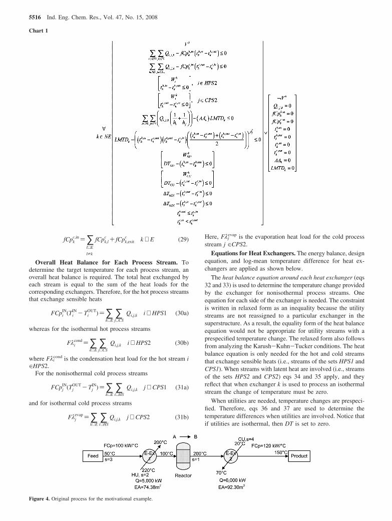
Figure 4. Original process for the motivational example.
5516 Ind. Eng. Chem. Res., Vol. 47, No. 15, 2008

The heat exchanger design equation 38 is relaxed as aninequality to determine the additional area required in eachmatch of the superstructure. In this way, when the existing areain a given match k (EAk) is not sufficient to meet the heat load,then the additional area required (AAk) is determined. Theadditional area is also limited by the objective function. If theexisting area is equal to or greater than the required area, thenadditional area is not necessary.
For the calculation of the log mean temperature difference(eq 39), Chen’s approximation is used to avoid singularities.28
Temperature difference constraints (eqs 40 and 41) are usedto ensure thermodynamic feasibility between the hot and coldstreams at the extremes of the heat exchangers. Notice that inthe model formulation it is not necessary to fix the heat recoverylevel, and only the minimum temperature difference allowedin any match of the superstructure, ∆TMIN, is used.
Temperature feasibility constraints (eqs 42 and 43) are neededto ensure the decrement of temperature for the hot processstreams and the increment for the cold process streams. Theseequations are also used for a correct application of eqs 34 and35 for isothermal streams.
The set of equations for the above concepts is given below.
∑i∈ HS1
∑j∈ CS
Qi,j,k - fCpkh,in(tk
h,in - tkh,out)e 0 k ∈ EE (32)
∑i∈ HS
∑j∈ CS1
Qi,j,k - fCpkc,in(tk
c,out - tkc,in)e 0 k ∈ EE (33)
tkh,in - tk
h,outeM1(1-wik) i ∈ HPS2, k ∈ EE (34)
tkc,out - tk
c,ineM1(1-wjk) j ∈ CPS2, k ∈ EE (35)
DTHUwHUk - (tk
h,in - tkh,out)e 0 k ∈ EE (36)
DTCUwCUk - (tk
c,out - tkc,in)e 0 k ∈ EE (37)
∑i∈ HS
∑j∈ CS
(Qi,j,k( 1hi+ 1
hj))- (EAk +AAk)LMTDke 0 k ∈ EE
(38)
LMTDk - ((tkh,in - tk
c,out)(tkh,out - tk
c,in)
((tkh,in - tk
c,out)(tkh,out - tk
c,in)
2 ))1/3
e 0 k ∈ EE (39)
∆TMIN - (tkh,out - tk
c,in)e 0 k ∈ EE (40)
∆TMIN - (tkh,in - tk
c,out)e 0 k ∈ EE (41)
tkh,oute tk
h,in k ∈ EE (42)
Table 1. Limits for the Operational Variables for Example 1
concept lower value upper value
FCp1IN (kW/°C) 96 132
FCp3IN (kW/°C) 80 110
T1IN (°C) 119.1 332.1
T3IN (°C) 80 120
Figure 5. Superstructure for Example 1.
Table 2. Piping Cost Data For Example 1
CONPk,lF CONPIs,k
F CONPEs,kF
k,l value ($/year) s,k value ($/year) s,k value ($/year)
1,2 1000 1,1 500 1,1 4001,3 1200 1,2 0 1,2 02,3 1300 1,3 500 1,3 600
2,1 0 2,1 02,2 250 2,2 4502,3 650 2,3 6003,1 0 3,1 03,2 450 3,2 4503,3 720 3,3 6004,1 350 4,1 4004,2 0 4,2 04,3 640 4,3 600
Ind. Eng. Chem. Res., Vol. 47, No. 15, 2008 5517

tkc,ine tk
c,out k ∈ EE (43)
For new exchanger units, the set of equations is applied onlyif the unit is selected for the retrofit network as part of theoptimization process. Therefore, the disjunction shown in Chart1 is written to account for new units in this chart, V and W areBoolean variables (that may be true or false), and the terms in
parentheses apply only if the Boolean variable is true. If weuse the big-M formulation to model the disjunction, thefollowing mixed-integer equations arise
∑i∈ HS1
∑j∈ CS
Qi,j,k - fCpkh,in(tk
h,in - tkh,out)eM3(1-Vk) k ∈ NE
(44)
Figure 6. Retrofitted HEN configuration for example 1.
Table 3. Results Comparison for Example 1
concept original process HEN retrofit without process optimization simultaneous HEN retrofit and process optimization
utility cost ($/year) 610,000 10,000 15,910capital cost ($/year) 0 900 900cost of row materials ($/year) 439,692,315 439,692,315 483,661,546sales of products ($/year) 510,638,532 510,730,466 561,702,386annual profit ($/year) 70,336,217 71,027,251 78,024,030
Figure 7. Original process for example 2.
5518 Ind. Eng. Chem. Res., Vol. 47, No. 15, 2008

∑i∈ HS
∑j∈ CS1
Qi,j,k - fCpkc,in(tk
c,out - tkc,in)eM4(1-Vk) k ∈ NE
(45)
tkh,in - tk
h,outeM1(1- µik) i ∈ HPS2, k ∈ NE (46)
tkc,out - tk
c,ineM2(1- µjk) j ∈ CPS2, k ∈ NE (47)
DTHUwHUk - (tk
h,in - tkh,out)eM5(1-Vk) k ∈ NE (48)
DTCUwCUk - (tk
c,out - tkc,in)eM6(1-Vk) k ∈ NE (49)
∑i∈ HS
∑j∈ CS
(Qi,j,k( 1hi+ 1
hj))- (EAk +AAk)LMTDke
M7(1-Vk) k ∈ NE (50)
LMTDk - ((tkh,in - tk
c,out)(tkh,out - tk
c,in)
((tkh,in - tk
c,out)+ (tkh,out - tk
c,in)
2 ))1/3
eM8(1-Vk) k ∈ NE (51)
∆TMIN - (tkh,out - tk
c,in)eM9(1-Vk) k ∈ NE (52)
∆TMIN - (tkh,in - tk
c,out)eM10(1-Vk) k ∈ NE (53)
Qi,j,keQi,jUPVk i ∈ HS, j ∈ CS, k ∈ NE (54)
fCpkh,ineFCph,UPVk k ∈ NE (55)
fCpkc,ineFCpc,UPVk k ∈ NE (56)
tkh,ine Th,in,UPVk k ∈ NE (57)
tkh,oute Th,out,UPVk k ∈ NE (58)
tkc,ine Tc,in,UPVk k ∈ NE (59)
tkc,oute Tc,out,UPVk k ∈ NE (60)
Table 4. Specifications for Example 2
design basis cost
product D $3.81/kmolfeed $0.65/kmolpurge gas $0.55/yeargenerated steam $1.8537 × 10⁻⁵/kJworking time 8376 h/yearpayout factor 0.3/yearutilities
cooling water 320-290 K $2.4642 × 10⁻⁶/kJhot utility 690-690 K $5.5613 × 10⁻⁵/kJpurchased electric power $0.025/kW hdemineralized water $2.34 × 10⁻³/kmolfixed cost for new heat
exchangers$3000
capital cost for new heatexchanger area (A in m2)
$1650A
compressor efficiency γ ) 1.4, ηm ) 0.9, ηc ) 0.8reactor conversion x ) 0.5 exp(-0.002T)(80/90)
P[yAyB/(1 + yC + yD)]
Antoine Constants (P in mmHg)
component A b C
A 13.6333 164.90 3.19B 14.3686 530.22 -13.15C 15.2243 897.84 -7.16D 18.5875 3626.55 -34.29
Film Heat Transfer Coefficients
stream h (kW/(m2 K))
H1 2.31H2 0.85CU 2.50C1 0.75C2 0.93C3 2.18CU 1.00
Constraints
reactor other
Toutlet g Tinlet 320K e Tflash e380KToutlet e 690 K 0epurge e100%
450 K e Tinlet e670KproductD eproduct(0.96)9atm epressure e29 atm0 econversion e100%
Table 5. Piping Cost Data for Example 2
CONPk,lF CONPIs,k
F CONPEs,kF
k,l value ($) s,k value ($) s,k value ($)
1,2 750 1,1 850 1,1 9901,3 810 1,2 0 1,2 7801,4 950 1,3 640 1,3 01,5 970 1,4 650 1,4 5401,6 780 1,5 760 1,5 5901,7 790 1,6 630 1,6 8501,8 770 1,7 635 1,7 8552,3 710 1,8 620 1,8 8402,4 740 2,1 0 2,1 02,5 830 2,2 670 2,2 4902,6 520 2,3 900 2,3 7502,7 530 2,4 1200 2,4 8102,8 510 2,5 1300 2,5 8403,4 560 2,6 750 2,6 6403,5 580 2,7 760 2,7 6503,6 640 2,8 740 2,8 6303,7 650 3,1 450 3,1 5203,8 620 3,2 500 3,2 5004,5 620 3,3 520 3,3 5404,6 730 3,4 0 3,4 04,7 740 3,5 0 3,5 04,8 720 3,6 620 3,6 5305,6 850 3,7 610 3,7 5205,7 860 3,8 630 3,8 5405,8 840 4,1 970 4,1 8806,7 520 4,2 820 4,2 7906,8 520 4,3 640 4,3 6307,8 520 4,4 530 4,4 670
4,5 0 4,5 04,6 970 4,6 7804,7 980 4,7 7904,8 960 4,7 7705,1 630 5,1 6405,2 0 5,2 05,3 540 5,3 5105,4 780 5,4 6105,5 820 5,5 7605,6 620 5,6 5905,7 630 5,7 6005,8 610 5,8 5806,1 980 6,1 9706,2 810 6,2 8106,3 780 6,3 6506,4 0 6,4 06,5 660 6,5 7606,6 830 6,6 8706,7 840 6,7 8806,8 810 6,8 8607,1 0 7,1 07,2 560 7,2 5607,3 0 7,3 07,4 810 7,4 7007,5 780 7,5 6807,6 670 7,6 6807,7 680 7,7 6907,8 660 7,8 670
Ind. Eng. Chem. Res., Vol. 47, No. 15, 2008 5519

AAkeAAUPVk k ∈ NE (61)
LMTDke LMTDUPVk k ∈ NE (62)
where V and w are 0-1 binary variables used to model theBoolean variables V and W.
Therefore, when a new heat exchanger is selected (Vk ) 1),eqs 44 to 53 are rigorously applied; otherwise, a big-Mparameter is used to relax the constraints, and all the variablesinvolved in the set of equations are set to zero by eqs 54 to 62.
In eq 46 the binary variable µik is activated when a new
exchanger k exists and the isothermal hot process stream i∈HPS2 is present in the match. The binary variable µj
k serves asimilar function in eq 47 for the isothermal cold process streams.The relations used to activate the binary variables µi
k and µjk
are given in eqs 18 and 19, respectively.Heat Loads for Heat Exchangers. To denote when a hot
process streams is processed by a given exchanger k, thefollowing inequality is used
Qi,j,k -QUPwike 0 i ∈ HS, k ∈ E (63)
Similarly for the cold process streams
Qi,j,k -QUPwjke 0 j ∈ CS, k ∈ E (64)
where QUP is an upper limit for the head load.Definition of Flows in Piping Segments. If there is any
amount of flow of a hot stream between exchangers k and l,then the piping segment zk,l
h must exist; otherwise, the pipingsegment does not exist
fCpk,lh -FCpUPzk,l
h e 0 k, l ∈ E, k* l (65)
Similarly, for the piping segment for a cold stream
fCpk,lc -FCpUPzk,l
c e 0 k, l ∈ E, k* l (66)
For any stream that leaves the HEN from a given exchangerk there is a piping segment. The binary variable zek is used inthe following constraints for the hot and cold sides of theexchanger
fCpk,exith -FCpUPzek
he 0 k ∈ E (67)
fCpk,exitc -FCpUPzek
ce 0 k ∈ E (68)
Feasibility Constraint for Isothermal Streams. For iso-thermal process streams, an additional constraint is needed toensure that the temperatures are the same in the interconnectionbetween two exchangers that service the same isothermal stream.These additional constraints are needed because the heatbalances for the heat exchanger (eqs 32 and 33) are relaxed forisothermal streams. Therefore, to avoid flows equal to zero whenexchanger k services an isothermal stream, the followingconstraints must be applied for hot and cold isothermal processstreams
fCpkh,ingFCpLOwi
k i ∈ HPS2, k ∈ EE (69)
fCpkc,ingFCpLOwj
k j ∈ CPS2, k ∈ EE (70)
where FCpLO is a lower limit for the heat capacity flow rate toavoid zero inlet mass flow to the heat exchanger.
Existing Exchangers Moved to a Different Location. Forthe cases where exchangers can be physically moved to adifferent location, the existing area of exchanger l, EAMl, canbe assigned to the position k by the following equation
EAk )∑l)1
K
(EAMlκk,l) k ∈ E (71)
It is worth mentioning that the cost associated to relocate aheat exchanger is usually higher than that for reconnecting new
Figure 8. Retrofit process for example 2.
5520 Ind. Eng. Chem. Res., Vol. 47, No. 15, 2008

streams to the heat exchanger. This situation is reflected in theobjective function.
Process Modeling Constraints. The types of process modi-fications depend upon each particular case. It is necessary toidentify the types of process modifications allowed for eachparticular case. We identify two types of process modifications.The first type is associated with process conditions, for exampleconversion, pressure, and temperature of reactors, temperatureand pressure of separation units, flow rates of purge, feed andproduct streams, and so forth. These variables are clearlyrestricted by feasibility conditions. A second type is related tostructural modifications of the process, for example the additionor replacement of equipment. Process modifications may affectthe temperatures and flow rates of the process streams and as aconsequence the utility requirements.
In this way, the constraints h and g represent material andenergy balances, design specifications and structural relation-ships as follows
h(x, z, y)) 0 (72)
g(x, z, y)e 0 (73)
where x represents the continuous variables of the process thatare involved in the HEN model (i.e., fCps
IN and TsIN for all the
process streams), z corresponds to the continuous variables thataffect the process but are not included in the HEN model (i.e.,pressures and temperatures of equipments, equipment sizes, etc.),and y represents the binary variables for structural modificationsin the flowsheet.
Objective Function. The objective function maximizes the totalannual profit of the process. The income in the objective function
Table 6. Results Comparison for Example 2
concept original process original process with HEN retrofit simultaneous retrofitted process
Costs ($/year)
raw materials 58,799,520.00 58,799,520.00 58,799,520.00hot utility 8,033,410.62 233,851.98 0.00cold utility 700,799.85 453,231.67 756,332.01electricity 2,897,998.30 2,897,998.30 2,278,500.00demineralized water 9,303,820.08 9,303,820.08 3,165,612.90capital exchangers 0 76,083.69 7,399.73piping 0 1,905.00 849.00total costs 79,735,548.85 71,766,410.72 65,008,213.64
Earnings ($/year)
product 135,942,969.55 135,942,969.55 158,950,000.00purge 11,138,588.39 11,138,588.39 4,482,500.00generated vapor 9,240,876.40 9,240,876.40 3,144,196.39total earnings 156,322,434.34 156,322,434.34 166,576,696.39annual profit 76,586,885.49 84,556,023.62 101,568,482.75
Figure 9. Solution of example 2 for retrofit HEN without process optimization.
Ind. Eng. Chem. Res., Vol. 47, No. 15, 2008 5521

depends on the sales of the products. The expenses depend on theraw materials, costs due to the modification in the processconditions, and the HEN retrofit annual cost. Additional expensesmay be considered for the purchase of new process equipment.The HEN retrofit costs include the hot and cold utilities cost, theannualized capital costs and fixed charges for new heat exchangers,the fixed charge for the new piping segments (which depends onthe distance between two exchangers k and l), the variable chargefor new piping segments (which depends on the distance and theamount of flow), and finally the cost to relocate a heat exchangerfrom one position to another.
max profit) ∑s∈ produc
COmsfs - ∑
s∈ rowmat
COmsfs - r(x, z, y)-
∑i∈ HU
∑j∈ CPS
∑k∈ E
COHU(Qi,j,k)- ∑i∈ HPS
∑j∈ CU
∑k∈ E
COCU(Qi,j,k)-
COAA∑k∈ E
AAk� -CONE ∑
k∈ NE
(Vk)-∑k∈ E
∑l∈ E
(CONPHk,l
F zk,lh +
CONPCk,l
F zk,lc )-∑
k∈ E∑l∈ E
CONPk,l
V (fk,lh + fk,l
c )-
∑s∈ HCS
∑k∈ E
CONPEs,k
F (yesk)- ∑
s∈ HCS∑k∈ E
CNPEs,k
V -
∑s∈ HCS
∑k∈ E
CONPIs,k
F (yisk)- ∑
s∈ HCS∑k∈ E
CONPIs,k
V (fsk)-
∑k∈ E
∑l∈ E
COk,lMOV(κk,l) (74)
where the term ∑s∈producCOmsfsrepresents the income for theproducts sale and ∑s∈rowmatCOmsfs corresponds to the expensesfor the raw materials purchase. To represent the costs due tothe process modifications the term r(x,z,y) is used.∑i∈HU∑j∈CPS∑k∈ECOHU(Qi,j,k) and ∑i∈HPS∑j∈CU∑k∈ECOCU(Qi,j,k)correspond the hot and cold utility costs, respectively. Thecapital cost for additional area needed is given by COAA∑k∈EAAk
�
and the fixed cost for new heat exchanger units isCONE∑k∈NE(Vk). The fixed and variable costs for new piping
segments between exchangers k and l are represented by∑k∈E∑l∈E(CONPHk,l
F zk,lh + CONPCk,l
F zk,lc ) and ∑k∈E∑l∈ECONPk,l
V (fk,lh +
fk,lc ), respectively. ∑s∈HCS∑k∈ECONPEs,k
F (yesk) and ∑s∈HCS∑k∈ECNPEs,k
V
represent the fixed and variable costs for the new pipingsegments for the streams that exit the HEN, respectively. Torepresent the fixed and variable costs for new piping segmentsfor the streams at the inlet of the HEN the terms∑s∈HCS∑k∈ECONPIs,k
F (yisk) and ∑s∈HCS∑k∈ECONPIs,k
V (fsk) are used.
Finally, the term ∑k∈E∑l∈ECOk,lMOV(κk,l) is used to denote the cost
to relocate a heat exchanger from one position to another.To determine the variable cost for the new piping segments
from any exchanger at the exit of the network, the followingdisjunction is necessary,
[ Yesk
fk,outs CONPEs,k
V -CNPEs,k
V e 0 ] ∨ [ ¬Yesk
CNPEs,k
V ) 0 ], s ∈ HCS, k ∈ E
which can be formulated as a big-M constraint
fk,outs CONPEs,k
V -CNPEs,k
V eM11(1- yesk), s ∈ HCS, k ∈ E
(75)
Figure 10. Existing HEN for example 3.
Table 7. Stream Data for Example 3
stream FCpsIN (kW/K) Ts
IN (K) TsOUT (K) h (kW/(m2 K))
H1 30 443 333 1.6H2 15 423 303 1.6HU - 450 450 4.8C1 20 293 408 1.6C2 40 353 413 1.6CU - 293 313 1.6
Table 8. Piping Costs for Example 3
CONPHk,lF CONPCk,l
F CONPIs,kF CONPEk,out
F
k,lvalue
($/year) k,lvalue
($/year) s,kvalue
($/year) s,kvalue
($/year)
1,2 0 1,2 4100 1,1 3200 1,1 41001,3 4500 1,3 4500 1,2 3600 1,2 34001,4 5700 1,4 5700 1,3 0 1,3 31001,5 3900 1,5 0 1,4 3800 1,4 01,6 3800 1,6 3800 1,5 3100 1,5 34002,3 3700 2,3 0 1,6 3400 1,6 31002,4 3900 2,4 3900 2,1 0 2,1 36002,5 3800 2,5 3800 2,2 3800 2,2 02,6 3950 2,6 3950 2,3 3800 2,3 32003,4 0 3,4 3700 2,4 4100 2,4 29003,5 3400 3,5 3400 2,5 3400 2,5 39003,6 2800 3,6 2800 2,6 3800 2,6 35004,5 3800 4,5 3800 3,1 3700 3,1 39004,6 3400 4,6 3400 3,2 3900 3,2 38005,6 3600 5,6 3600 3,3 3200 3,3 3400
3,4 3800 3,4 36003,5 0 3,5 03,6 3400 3,6 34004,1 3200 4,1 36004,2 0 4,2 34004,3 3500 4,3 04,4 3700 4,4 33004,5 3900 4,5 29004,6 4000 4,6 28005,1 0 5,1 35005,2 3100 5,2 38005,3 3600 5,3 33005,4 3800 5,4 37005,5 3600 5,5 05,6 3900 5,6 31006,1 3700 6,1 37006,2 3400 6,2 33006,3 2900 6,3 27006,4 0 6,4 06,5 3700 6,5 32006,6 2800 6,6 3100
5522 Ind. Eng. Chem. Res., Vol. 47, No. 15, 2008
CNPEs,k
V eM11yesk, s ∈ HCS, k ∈ E (76)
where M11 is an upper limit.Remarks
1. The MINLP model considers the plant layout and thepiping structure explicitly.
2. The superstructure model allows complex piping configu-rations and does not require assumptions commonly used suchas isothermal mixing, no bypass streams, and no splitting ofstreams.
3. The model formulation can consider the fixed and variablepiping costs depending on the distance and the flow rate. Inaddition, the model formulation can consider the relocation ofa given heat exchanger.
4. The model presented considers explicitly the interactionsbetween the modifications in process conditions and the heatintegration.
5. The model takes into account the existing units and theoriginal conditions as well as the new units needed and themodifications of the operating conditions in the retrofit process.
6. The MINLP model includes the treatment of hot and coldprocess isothermal streams.
7. The MINLP model is nonconvex. Therefore, the optimalsolution can only be guaranteed with global optimizationmethods.29 However, local methods like DICOPT30 can oftenfind near optimal solutions that may be satisfactory for manypractical applications.
4. Examples
Example 1. This is a fairly simple problem that is used as amotivating example. Consider the process shown in Figure 4,
in which the feed must be heated until a given target temperatureand then processed in a reactor with a final cooling process.The film heat transfer coefficients for all streams in thissimplified example are assumed as 1 kW/(m2 °C). The heatcapacity for components A and B are 4.17 kJ/(kg °C) and 5kJ/(kg °C), respectively. The operation time of the plant is 8500h/year. The hot and cold utilities cost are $110/kW-year and$10/kW-year, respectively. The prices for the components Aand B (COmA and COmB) are $0.5987/kg and $0.6953/kg,respectively. The cost for new exchangers is given by $700A,where A is given in m2.
The reaction is assumed to be exothermic with a heat ofreaction equal to 818.94 kJ/kg. The reactor has a volume of 50m3 and operates at a constant pressure of 10 kPa. The conversionof the reaction depends only on the inlet temperature to thereactor
conversion) 0.87 exp(-0.002Tinreac) (77)
where Tinreac is in °C.The limits given in Table 1 are included to reflect the
availability and demand for the materials, as well as limitationson the operation conditions.
The superstructure shown in Figure 5 is used for the solutionof this problem. It includes 3 heat exchangers, 2 of them arepart of the original process and a new exchanger is consideredas a potential unit for the optimal configuration. Table 2 showsthe additional piping cost data for the retrofit problem.
The additional process constraints for this example are themass and energy balances in the reactor, which are related tothe temperatures and flows of the process streams. Notice thatfor this simple problem the superstructure needed to account
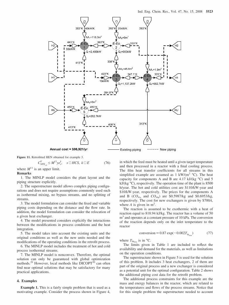
Figure 11. Retrofitted HEN obtained for example 3.
Ind. Eng. Chem. Res., Vol. 47, No. 15, 2008 5523

for process modifications and energy integration gives rise toan MINLP problem that contains 145 constraints and 115variables (with 29 binary variables).
The solver DICOPT implemented in the General AlgebraicModeling Systems30 was used to solve the resulting MINLPmodel for this problem, requiring 0.53 s of CPU time. Theretrofitted HEN is shown in Figure 6. The retrofitted configu-ration shows an improvement in the heat integration of theprocess without the need for additional area. Table 3 shows acomparison of the annual profit of the retrofitted process withrespect to the original process. As can be seen, the simultaneousoptimization and HEN retrofit yields a considerable improve-ment in the process profit (10.93% with respect to the originalprocess). Table 3 also shows the results for the optimal HEN
retrofit keeping the original process conditions unchanged, inwhich case the improvement is only 0.98%.
Example 2. This example takes a retrofit problem from anextension of a process discussed by Duran and Grossmann22
(see Figure 7). The feed involves three chemical species A, B,and C, where C is an inert component. The feed mixture istreated with a two-stage compressor with intermediate coolingto raise its pressure, and then mixed with a recycle stream. Theresulting stream is preheated with the reactor outlet stream andfed to the reactor where the components A and B react in anexothermic reaction to produce D. The effluent of the reactoris cooled and sent to a flash unit to recover the product D inthe liquid stream. The product stream (liquid from the flash) isheated to deliver the product as saturated vapor. A fraction ofthe resulting vapor stream of the flash is purged to avoid theaccumulation of inert C in the process. The purged stream isfinally heated to a required temperature.
The data for the process specifications are given in Table 4.The phase equilibrium in the flash is predicted with an idealmodel, while isentropic compression corrected by efficiencyfactors is assumed for the compressors. For the process streams,heat capacities are assumed to be linear functions of composition.
Table 9. Results Comparison for Example 3
conceptYee and
Grossmann12 Ma et al.13 this work
new area (m2) 187.28 167.05 166.18new units 1 1 0utility cost ($/year) 24667.00 23300.00 34277.79capital exchangers cost ($/year) 56818.80 51762.50 41 544.00capital piping cost ($/year) 20600.00 45900.00 23100total annual cost ($/year) 102085.80 120962.50 98921.79
Figure 12. Existing HEN for example 4.
5524 Ind. Eng. Chem. Res., Vol. 47, No. 15, 2008

Table 5 shows the piping cost associated to the retrofit ofthe streams.
A superstructure with five existing heat exchangers and threenew units was used for this problem. The resulting MINLPmodel contained 1094 constraints with 852 variables, whichincluded 296 binary variables. After solving this problem withGAMS/DICOPT software in 240.35 s of CPU time, we obtainedthe retrofit process shown in Figure 8. The new conditions inthe retrofitted process are such that no hot utilities are required.In addition, new piping segments for the hot stream effluent tothe reactor (H1 stream) are needed to obtain a better heatintegration with the cold process streams C1, C3, and C2 inexchangers 5, 4, and 2, respectively, and a cold utility is usedin exchanger 3 to provide the temperature needed at the inletof the flash. None of the new exchangers formulated as part ofthe superstructure were selected. Only additional area inexchanger 1 of 14.95 m2 was needed. The total annual profitobtained from the simultaneous optimization of the process andthe HEN retrofit is $101 568 482/year. Table 6 reports the resultsfrom the economics for the retrofitted process and for theoriginal process. Notice how the retrofitted process provides anoticeable improvement in the annual profit.
When the retrofit problem was formulated without processmodifications, the solution shown in Figure 9 was obtained. Atotal annual profit of $84 556 338/year was obtained in this case.Notice in Figure 9 that if the simultaneous HEN retrofit-processconditions optimization is not conducted, a new heat exchangerand several piping modifications are needed to reduce the utilityconsumption. In addition, the simultaneous process and HENretrofit optimization produces a better heat integration (there isin that case no need for hot utilities). The simultaneous retrofitoptimization has a total profit 32.6% higher than the originalprocess, which is significantly better that the improvement of10.4% provided when only the HEN retrofit was considered.
Example 3. This example was taken from Yee and Gross-mann12 to show the application of the proposed methodologyfor HEN retrofit when the process conditions are fixed. Theexisting HEN is shown in Figure 10, with the stream data givenin Table 7. The information for the costs for new pipingsegments is shown in Table 8. The hot and cold utility costsare $80/(kW-year) and $20/(kW-year), respectively. The fixedcost for new heat exchangers units is $10 000/year and the costfor additional heat transfer area is $250/(m2 year). The annualutility cost for the existing HEN is $158 000/year. To solve thisproblem, a superstructure with six heat exchangers was devel-oped, five exchangers exist in the original HEN, and one newunit was considered. The model involved 578 constraints and452 variables, with 180 binary variables and required 16.4 s ofCPU time for its solution.
Figure 11 shows the retrofitted network obtained using theproposed methodology. The few modifications needed for theexisting process consist of piping modifications and additionalarea in exchangers 1, 3, and 4, which reduce the total annualcost to $98 921/year. Note that the new heat exchanger
considered in the superstructure was not needed. Table 9 showsa comparison of the results obtained in this work with the onespreviously obtained by Yee and Grossmann12 and Ma et al.13
for the same stream data. The application of the proposedmethodology yields a reduction of 37.4% in the total annualcost with respect to the original HEN, whereas the solutions of
Table 10. Stream Data for Example 4
streamTs
IN (K) TsOUT (K)
typeFCps
IN (kW/ K) orFλs (kW)
h (kW/(m2 K))
H1 480 320 HPS1 55 0.83H2 420 420 HPS2 28090 1.82H3 390 390 HPS2 11213 1.73HU 627 627 HU - 2.5C1 330 490 CPS1 53 0.72C2 391 391 CPS2 18320 1.91C3 349 349 CPS2 12640 1.84CU 303 315 CU - 1.0
Table 11. Piping Costs Information for Example 4
CONPHk,lF CONPCk,l
F CONPIs,kF CONPEs,k
F
k,lvalue
($/year) k,lvalue
($/year) s,kvalue
($/year) s,kvalue
($/year)
1,2 7400 1,2 7400 1,1 0 1,1 42001,3 8300 1,3 8300 1,2 5700 1,2 41001,4 0 1,4 4300 1,3 5800 1,3 39001,5 9200 1,5 9200 1,4 5800 1,4 01,6 3500 1,6 0 1,5 6000 1,5 28001,7 6700 1,7 6700 1,6 3400 1,6 52001,8 6300 1,8 6300 1,7 4000 1,7 60002,3 5200 2,3 5200 1,8 4200 1,8 53002,4 5700 2,4 5700 2,1 3500 2,1 52002,5 0 2,5 3700 2,2 0 2,2 51002,6 3950 2,6 3950 2,3 4700 2,3 38002,7 5300 2,7 5300 2,4 5600 2,4 28002,8 5400 2,8 5400 2,5 5700 2,5 03,4 4500 3,4 4500 2,6 3800 2,6 50003,5 3900 3,5 3900 2,7 4300 2,7 54003,6 5200 3,6 5200 2,8 4200 2,8 48003,7 6900 3,7 0 3,1 3700 3,1 53003,8 5200 3,8 5200 3,2 3900 3,2 48004,5 3600 4,5 3600 3,3 0 3,3 04,6 5000 4,6 5000 3,4 4200 3,4 34004,7 8700 4,7 8700 3,5 5300 3,5 29004,8 4500 4,8 4500 3,6 2400 3,6 53005,6 6500 5,6 6500 3,7 4200 3,7 55005,7 7800 5,7 7800 3,8 3300 3,8 43005,8 5600 5,8 5600 4,1 3200 4,1 56006,7 4200 6,7 4200 4,2 4300 4,2 52006,8 6200 6,8 6200 4,3 3500 4,3 51007,8 5300 7,8 5300 4,4 3700 4,4 4900
4,5 3900 4,5 48004,6 0 4,6 04,7 0 4,7 04,8 2900 4,8 34005,1 0 5,1 37005,2 3100 5,2 43005,3 3050 5,3 45005,4 3800 5,4 54005,5 3600 5,5 54005,6 3900 5,6 05,7 4500 5,7 29005,8 3500 5,8 36006,1 3700 6,1 41006,2 0 6,2 06,3 2900 6,3 44006,4 3800 6,4 47006,5 3700 6,5 48006,6 4200 6,6 32006,7 4500 6,7 31006,8 3900 6,8 38007,1 4100 7,1 39007,2 4050 7,2 42007,3 0 7,3 41007,4 3900 7,4 51007,5 3800 7,5 53007,6 4100 7,6 28007,7 4300 7,7 07,8 3700 7,8 31008,1 3500 8,1 45008,2 3450 8,2 44008,3 3400 8,3 46008,4 0 8,4 08,5 0 8,5 08,6 4200 8,6 43008,7 4300 8,7 45008,8 5200 8,8 5500
Ind. Eng. Chem. Res., Vol. 47, No. 15, 2008 5525

Yee and Grossmann12 and Ma et al.13 provide reductions by35.4% and 23.4%, respectively. Notice that the piping modifica-tion costs turn out to be very significant for this problem becauseof the plant layout. It is important therefore to include suchcosts in model formulations for these types of problems.
Example 4. This example considers the retrofit of a HENwith both isothermal and nonisothermal process streams. Theprocess conditions are fixed in this case. The existing networkshown in Figure 12 has a total annual cost of $529 800/year.Table 10 lists the stream data, and Table 11 gives the capitalcost for new piping segments. The capital cost for new heatexchanger area is calculated by $380A/year (A in m2), and thehot and cold utility costs are $110/(kW year) and $20/(kW year),respectively. Notice that the process streams H1 and C1exchange sensible heat, whereas H2, H3, C2 and C3 areisothermal process streams that exchange their latent heats.
To solve this problem, a superstructure with seven existingheat exchangers and one potential new unit was formulated.The superstructure involves 1300 constraints and 872 variables,with 320 binary variables, and was solved with DICOPT in104.2 s of CPU time. The retrofitted network obtained usingthe proposed MINLP model is shown in Figure 13. Minor pipingmodifications and additional exchanger areas are needed.
However, no new exchanger is required in the optimal solutionprovided by the model. The piping modifications require acapital cost of $30 700/year. The additional area is needed forunits 4, 5, and 7 by 0.06, 13.88, and 73.716 m2, respectively,which requires an annualized capital cost of $33 310/year. Themodifications in the retrofitted HEN reduce the utility consump-tion by 34.6%. This significant improvement was obtainedbecause the formulation presented in this work includes a propertreatment for energy integration of both isothermal and noniso-thermal types of process streams. Finally, the total annual costof the retrofitted HEN is $410 530/year, which yields a reductionin the total annual cost of 22.5% with respect to the originalHEN. Table 12 shows a summary of the costs for the originalHEN and the retrofitted HEN.
One may notice that the solution calls for what seems likean impractical low value of the additional area for exchanger4. One could easily correct this situation by implementing aconstraint to set this additional area to zero. Also, one couldtailor the model implementation to some practical retrofit policyon this matter through the implementation of appropriate lowerbounds for any additional area.
It is worth mentioning that the utility consumption in theretrofitted HEN can be reduced even further if the heat load
Figure 13. Retrofit HEN for example 4.
5526 Ind. Eng. Chem. Res., Vol. 47, No. 15, 2008

exchanged between streams H1 and C1 in unit 1 is increased,but this utility reduction would require an additional area forexchanger 1 that would yield a higher total annual cost thanthe one reported here.
It should be noted how the number of binary variablesaffected the computational effort for each problem. As thenumber of binary variables increases, the number of possiblecombinations grows exponentially, thus affecting the CPU time.
5. Conclusions
This paper has presented an MINLP formulation for theretrofit of chemical processes considering simultaneously processmodifications and heat integration. The model considers the plantlayout and complex piping configurations. The superstructureused for the heat exchanger networks configuration is generaland does not require imposing constraints such as no bypass orno splitting of streams. Also, the model formulation includesthe treatment of isothermal process streams. For the economicassessment of alternatives, a simultaneous consideration isincluded for the capital cost of the new exchanger units, theadditional area required, and the new piping segments, as wellas the operating cost for hot and cold utilities. Fixed and variablepiping costs can be considered in the model formulation, aswell as the relocation of heat exchangers within the process.
The examples presented here show that significant earningscan be obtained in the retrofit process when the processmodifications and the heat integration retrofit are consideredsimultaneously, as opposed to the solution given by theconsideration of heat integration restricted with unchangedprocess conditions.
Acknowledgment
This work was performed while A. Jimenez was a Fulbright-Garcıa Robles Scholar at Carnegie Mellon University.
Nomenclature
AAk ) additional area required by exchanger kAEAk ) existing area assigned to existing exchanger kCNPEs,k
V ) variable cost for new piping segment from exchanger kto the exit of stream s
COms ) price of material sCOAA ) unit cost for new areaCONPIs,k
F ) fixed cost for new initial piping segment of stream s toexchanger k
CONPIs,kV ) variable cost for new initial piping segment of stream s
to exchanger kCONE ) fixed cost for new heat exchangersCONPk,l
F ) fixed cost for new piping segment between exchangers kand l
CONPk,lV ) variable cost for new piping segment between exchangers
k and l depending upon the mass flowCONPEs,k
F ) fixed cost for piping segment for exchanger k to theexit of stream s
CONPEs,kV ) variable cost for piping segment for exchanger k to the
exit of stream s depending upon the mass flowCOk,l
MOV ) cost of moving one exchanger from position k to positionl
CPS ) set containing the total cold process streams, CPS1∪CPS2CPS1 ) set containing the cold process nonisothermal streamsCPS2 ) set containing the cold process isothermal streamsCS ) set containing the total cold streams, CPS∪CUCS1 ) set containing the cold process nonisothermal streams and
the cold utilities, CPS1∪CUCU ) set containing the cold utilitiesDTCU ) prespecified temperature change for the cold utilityDTHU ) prespecified temperature change for the hot utilityE ) set containing any exchanger in the superstructureEE ) set containing the existing exchangers in the networkEAk ) existing area of exchanger kEAMl ) existing area of exchanger l that can be relocated in the
plantf ) mass flow rateFCps
IN ) total heat capacity flow rate for stream sFCpCU ) upper limit for the heat capacity flow rate for the cold
utilityFCpHU ) upper limit for the heat capacity flow rate for the hot
utilityfCps
k ) initial heat capacity flowrate of stream s to exchanger kfCpk
c,in ) inlet heat capacity flow rate for the cold side of exchangerk
fCpl,kc ) heat capacity flow rate for the cold side from exchanger l
to exchanger kfCpk,exit
c ) heat capacity flow rate for the cold side from exchangerk to the exit of the HEN
fCpkh,in ) inlet heat capacity flow rate for the hot side to exchanger
kfCpl,k
h ) heat capacity flow rate for the hot side from exchanger lto exchanger k
fCpk,exith ) heat capacity flow rate for the hot side from exchanger
k to the exit of the HENg(x,z,y) ) set of inequality constraints for the process modelh ) individual film heat transfer coefficienth(x,z,y) ) set of equality constraint for the process modelHPS ) set containing the hot process streams, HPS1∪HPS2HPS1 ) set containing the hot process nonisothermal streamsHPS2 ) set containing the hot process isothermal streamsHS ) set containing the total hot streams, HPS∪HUHS1 ) set containing the total nonisothermal streams plus utilities,
HS1 ) HPS1∪HUHU ) set containing the hot utilitiesHCPS ) set containing the hot and cold process streams, HPS∪CPSHCT ) set containing the total streams, HS∪CSK ) number of exchangers in the superstructureLMTDk ) log-mean temperature difference for exchanger kM ) big-M parameter used for constraintsNE ) set containing the new exchangers in the superstructureNP ) set containing the new piping segmentsNPE ) set to denote that stream s does not enter existing HEN at
exchanger kQi,j,k ) head load exchanged between streams i and j in exchanger
kr(x,z,y) ) costs due to process modificationsTs
IN ) inlet temperature of stream s to HENTs
OUT ) outlet temperature of stream s from HENtkc,in ) inlet temperature of cold stream to exchanger k
tlc,out ) outlet temperature of cold stream from exchanger l
tkh,in ) inlet temperature of hot stream to exchanger k
Table 12. Results for Example 4
concept original HEN retrofitted HEN
new area (m2) 0 87.66new units 0 0utility cost ($/year) 529800 346520capital exchangers cost ($/year) 0 33310capital piping cost ($/year) 0 30700total annual cost ($/year) 529800 410530
Ind. Eng. Chem. Res., Vol. 47, No. 15, 2008 5527

tlh,out ) outlet temperature of hot stream from exchanger lVk ) binary variable to denote the existence of a new heat exchanger
unit in the retrofitted networkws
k ) binary variable to denote that stream s is assigned to exchangerk
x ) vector of continuous variables in the HEN modelxs
k,l ) binary variable to denote that exchangers k and l service thesame process stream s
y ) vector of binary variables in the model for structuralmodifications in the flowsheet
yisk ) binary variable to denote that inlet stream s is assigned toexchanger k
yeks ) binary variable to denote the exit of stream s from exchan-ger k
z ) vector of continuous variables of the process that are notincluded in the HEN model
zk,l ) binary variable to denote the piping segment connectingexchangers k and l
zek ) binary variable to denote the existence of piping segmentfrom exchanger k to exit of HEN
Greek SymbolsFλi
cond ) condensation heat load for stream iFλj
evap ) evaporation heat load for stream j∆TMIN ) minimum temperature differenceκk,l ) binary variable to assign the existing area of exchanger l to
the location of exchanger kµs
k ) binary variable to denote that isothermal stream s is assignedto exchanger k
Indicesi ) hot streamj ) cold streamk ) exchanger in the superstructurel ) exchanger in the superstructureSubscripts and Superscriptsc ) cold sideh ) hot sides ) any streamexit ) network exit pointIN ) inlet to the HENin ) inlet to an exchangerLO ) lower limitOUT ) outlet from the HENout ) outlet from an exchangerUP ) upper limit
Literature Cited
(1) Furman, K. C.; Sahinidis, N. V. A critical review and annotatedbibliography for heat exchanger network synthesis in the 20th century. Ind.Eng. Chem. Res. 2002, 41, 2335–2370.
(2) Jezowski, J. Heat exchanger network grassroot and retrofit design.The review of the state-of-the-art: Part I. Heat exchanger network targetingand insight based methods of synthesis. Hung. J. Ind. Chem. 1994, 22 (4),279–294.
(3) Jezowski, J. Heat exchanger network grassroot and retrofit design.The review of the state-of-the-art: Part II. Heat exchanger network synthesisby mathematical-methods and approaches for retrofit design. Hung. J. Ind.Chem. 1994, 22 (4), 295–308.
(4) Gundersen, T.; Naess, L. The synthesis of cost optimal heatexchanger networks -An industrial review of the state of the art. Comput.Chem. Eng. 1988, 12 (6), 503–530.
(5) Linnhoff, B.; Vredeveld, D. R. Pinch technology has come of age.Chem. Eng. Prog. 1984, 80 (7), 33–40.
(6) Tjoe, T. N.; Linnhoff, B. Using pinch technology for process retrofit.Chem. Eng. 1986, 93 (8), 47–60.
(7) Linnhoff, B.; Hindmarsh, E. The pinch design method for heatexchanger networks. Chem. Eng. Sci. 1983, 38 (5), 745–763.
(8) Polley, G. T.; Shahi, M. H. P.; Jegede, F. O. Pressure dropconsiderations in the retrofit of heat exchanger networks. Chem. Eng. Res.Des. 1990, 68 (3), 211–220.
(9) Ciric, A. R.; Floudas, C. A. A mixed integer nonlinear-programmingmodel for retrofitting heat exchange-networks. Ind. Eng. Chem. Res. 1990,29, 239–251.
(10) Papoulias, S. A.; Grossmann, I. E. A structural optimizationapproach in process synthesis. II. Heat recovery networks. Comput. Chem.Eng. 1983, 7 (6), 707–721.
(11) Floudas, C. A.; Ciric, A. R.; Grossmann, I. E. Automatic synthesisof optimum heat exchanger network configurations. AIChE J. 1986, 32 (2),276–290.
(12) Yee, T. F.; Grossmann, I. E. A screening and optimization approachfor the retrofit of heat exchanger networks. Ind. Eng. Chem. Res. 1991, 30,146–162.
(13) Ma, K. L.; Hui, C. W.; Yee, T. F. Constant approach temperaturemodel for HEN retrofit. App. Therm. Eng. 2000, 20 (15-16), 1505–1533.
(14) Yee, T. F.; Grossmann, I. E. Simultaneous optimization modelsfor heat integration II-Heat exchanger network synthesis. Comput. Chem.Eng. 1990, 14 (10), 1165–1184.
(15) Briones, V.; Kokossis, A. C. Hypertargets: a conceptual program-ming approach for the optimization of industrial heat exchanger networks-II Retrofit design. Chem. Eng. Sci. 1999, 54 (4), 541–561.
(16) Sorsak, A.; Kravanja, Z. MINLP retrofit of heat exchanger networkscomprising different exchanger types. Comput. Chem. Eng. 2004, 28 (1-2), 235–251.
(17) Bjork, K. M.; Nordman, R. Solving large-scale retrofit heatexchanger network synthesis problems with mathematical optimizationmethods. Chem. Eng. Process. 2005, 44 (8), 869–876.
(18) Nie, X. R.; Zhu, X. X. Heat exchanger network retrofit consideringpressure drop and heat-transfer enhancement. AIChE J. 1999, 45 (6), 1239–1254.
(19) Lopes-Silva, M.; Zemp, J. Retrofit of pressure drop constrainedheat exchanger networks. Appl. Therm. Eng. 2000, 20 (15-16), 1469–1480.
(20) Athier, G.; Floquet, L.; Pibouleau, L.; Domenech, S. A mixedmethod for retrofitting heat-exchanger networks. Comput. Chem. Eng. 1998,22, s505–s511. (Suppl.)
(21) Zhu, X. X.; Asante, N. D. K. Diagnosis and optimization approachfor heat exchanger network retrofit. AIChE J. 1999, 45 (7), 1488–1503.
(22) Duran, M. A.; Grossmann, I. E. Simultaneous optimization andheat integration of chemical processes. AIChE J. 1986, 32 (1), 123–138.
(23) Lang, Y. D.; Biegler, L. T.; Grossmann, I. E. Simultaneousoptimization and heat integration with process simulators. Comput. Chem.Eng. 1988, 12 (4), 311–327.
(24) Grossmann, I. E.; Yeomans, H.; Kravanja, Z. A rigorous disjunctiveoptimization model for simultaneous flowsheet optimization and heatintegration. Comput. Chem. Eng. 1998, 22, S157–S164.
(25) Zhang, J.; Zhu, X. X. Simultaneous optimization approach for heatexchanger network retrofit with process changes. Ind. Eng. Chem. Res. 2000,39, 4963–4973.
(26) Ponce-Ortega, J. M.; Jimenez-Gutierrez, A.; Grossmann, I. E.Optimal synthesis of heat exchanger networks involving isothermal processstreams. Comput. Chem. Eng., 2008, 32 (9), 1918–1942.
(27) Liporace, F. S.; Pessoa, F. L. P.; Queiroz, E. M. Heat exchangernetwork synthesis considering change phase streams. Therm. Eng. 2004, 3(2), 87–95.
(28) Chen, J. J. J. Comments on improvement on a replacement for thelogarithmic mean. Chem. Eng. Sci. 1987, 42 (10), 2488–2489.
(29) Furman, K. C.; Sahinidis, N. V. Computational complexity of heatexchanger network synthesis. Comput. Chem. Eng. 2001, 25 (9-10), 1371–1390.
(30) Brooke, A.; Kendrick, D.; Meeraus, A.; Raman, R. GAMS-Languageguide; GAMS Development Corporation: Washington, DC, 2006.
ReceiVed for reView August 31, 2007ReVised manuscript receiVed February 28, 2008
Accepted March 12, 2008
IE071182+
5528 Ind. Eng. Chem. Res., Vol. 47, No. 15, 2008