simulation of the bessy ii vacuum system
TRANSCRIPT

Nuclear Instruments and Methods in Physics Research A 470 (2001) 18–22
Simulation of the BESSY II vacuum system
D. Richter
Berliner Elektronenspeicherring-Gesellschaft f .uur Synchrotronstrahlung, BESSY, 12489 Berlin, Germany
Abstract
The pressure distribution of the BESSY II storage ring vacuum system is simulated to obtain a better knowledge of
the vacuum situation and the influence of additional gas sources. The vacuum system is transformed into an electricalnetwork. Using a commercial computer program (Program OrCad, Fa. OrCad, Beaverton, USA, 1998) the parametersof the network are transformed into vacuum related values. The results are described. r 2001 Elsevier Science B.V. Allrights reserved.
PACS: 07.30.@t; 07.30.Hd
Keywords: Vacuum system; Storage ring
1. Introduction
The pressure in an ultra-high vacuum systemdepends on the pumping speed, the outgassing rateof the vacuum chamber walls and additional gassources. The existence of pressure gradients isexplained in the example of one vacuum pumpconnected to a simple tube. It is evident that thepressure is minimal at the vacuum pump. We havedifferent pressure gradients along the tube. Divid-ing the tube into a lot of sections, in every slice agas current is desorbed from the chamber wallsurface. These gas currents flow to the pump. Thisresults a superposition of the gas currents in everyslice. The currents cause a pressure gradientDp ¼ (QQ=L: Here the term L is the conductanceof the slice. The outgassing rate is the quotient ofthe gas current and the outgassing area, thus:
d
dtpVð Þ=A:
The outgassing rate is not a constant in the cham-ber element considered. Transforming the vacuumsystem into an electrical network, the inverse ofthe conductance is equivalent to a resistor, while avacuum pump corresponds to a resistor with avalue inverse of the pumping speed. The gas flowsare constant current sources. The voltages at everynodes are the direct results of the calculation.
2. The network
The BESSY II vacuum system consists of 16identical sections with a length of about 15 m. Onesection is pumped by 10 sputter ion pumps (75 l/s),and two sputter ion pumps (500 l/s) (Fig. 1). Thenetwork contains all vacuum components impor-tant for the pressure distribution. The beamchamber is divided into 90 elements. The pumptubes consist of two or five elements depending onthe construction. Fig. 2 shows a section of thegenerated electrical network. It contains a pumpE-mail address: [email protected] (D. Richter).
0168-9002/01/$ - see front matter r 2001 Elsevier Science B.V. All rights reserved.
PII: S 0 1 6 8 - 9 0 0 2 ( 0 1 ) 0 0 9 9 4 - 9

tube with a sputter getter pump (75 l/s), a dipolechamber, the absorber and a pump tube with alarge pump (500 l/s) at the exit side of the dipolechamber. The location of the pressure measure-ment gauge and the intersection between mainchamber and the pump tube are stretched.
3. The dependence of the pumping speed on the
pressure
To obtain reasonable results it is necessary toconsider the fact that the pumping speed ofvacuum pumps depends on the total pressure. Atfirst, the calculation step of the nominal pumpingspeed is used. The resultant pressure values arevery small, because the real pumping speed islower in the ultra-high vacuum range. The inter-dependence pumping speed vs. pressure is known.The next step is made of the calculation of a morerealistic, lower pumping speed, and follows a newcalculation of the pressures.
After three or four iteration steps the pumpingspeed approaches a stable value. Fig. 3 shows anexample of a small pump. The pumping speed ofthe vacuum pumps in the neighbourhood of theconsidered vacuum section is taken into account.The average pressure is defined as
pav ¼1
lmax
Z lmax
0
pðlÞdl:
In this formula, the term pðlÞ is the pressuredistribution in the main chamber with the length lmax.
4. The pressure distribution
4.1. The pressure distribution without beam
First the pressures were calculated in the mainchamber without the storaged electron beam. Theaverage pressure is called basic pressure.A constant outgassing rate is assumed from all
Fig. 1. Section of the storage ring under consideration.
Fig. 2. A section of the electrical network.Fig. 3. Iteration of the pumping speed to the real value.
D. Richter / Nuclear Instruments and Methods in Physics Research A 470 (2001) 18–22 19

chamber walls, including the pump tubes. Fig. 4shows the calculated pressure distributions for thecase of outgassing rates of ((1)y1� 10@13,(2)y5� 10@13, (3)y1� 10@12, (4)y5� 0@12
mbar l/s cm2). The resulting basic pressure vs. theoutgassing rate is plotted in Fig. 5.
The calculation capitulates to an outgassing rateof 2� 10@13 mbar l/s cm2 to obtain the desiredbasic pressure of 5� 10@11 mbar [1]. In the realmachine, the basic pressure is approximately10@10 mbar, which means the outgassing rate isabout 1� 10@12 mbar l/s cm2. These numberswould be significantly lower if baking tempera-tures in excess of 1501C would be applied [2].
4.2. The pressure distribution with stored electronbeam
The calculation in the presence of a beam ismade in two steps. At first, the influence of the
additional gas stream from the chamber walls istaken into consideration. This current is caused byan interaction of synchrotron radiation with thechamber walls resulting in stimulated desorption.The second step considers the influence of the gascurrents coming from the absorbers which have toabsorb most of the power emitted by the beam.
4.2.1. Variation of the outgassing rate in the mainchamber
The pressure distribution calculated at severaloutgassing rates is shown in Fig. 6. The outgassingrate increases beginning with 1� 10@12 mbar l/s cm2 (graph 1) step by step by a factor of 10. Theoutgassing rate in the pump tubes is always1� 10@12 mbar l/s cm2.
Fig. 7 gives a plot of the average pressure vs. theoutgassing rate.
4.2.2. Consideration of the gas currents comingfrom the absorbers
During the operation of the storage ring asignificant gas load originates from the absorbers,which are located at the end of the dipolechambers (Fig. 8). Therefore, it is necessaryto take into consideration their influence onthe pressure distribution. A pressure distri-bution was measured along the whole storagering. The electron beam current was 100 mA andthe average pressure 1� 10@9 mbar. Pressurevalues of some 10@10 mbar are measured in bakedsections and at locations with a long distance toabsorbers. Therefore, an outgassing rate of1� 10@12 mbar l/s cm2 at all chambers is used forthe calculation. The corresponding calculatedpressure distributions is shown in Fig. 9. The gascurrent coming from the absorbers is varied in thecalculation. A gas current of 1� 10@6 mbar l/s isnecessary to reproduce the measured averagepressure of 1� 10@9 mbar.
5. The effect of the baking procedure
Baking can be applied to most of the sections ofthe BESSY vacuum system at a temperature of1201C. This temperature was chosen to pre-vent the risk of damage to the chambers and
Fig. 4. Pressure distribution at constant outgassing rate in all
chambers.
Fig. 5. Basic pressure vs. outgassing rate.
D. Richter / Nuclear Instruments and Methods in Physics Research A 470 (2001) 18–2220
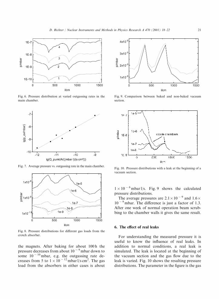
the magnets. After baking for about 100 h thepressure decreases from about 10@9 mbar down tosome 10@10 mbar, e.g. the outgassing rate de-creases from 5 to 1� 10@12 mbar l/s cm2. The gasload from the absorbers in either cases is about
1� 10@6 mbar l/s. Fig. 9 shows the calculatedpressure distributions.
The average pressures are 2.1�10@9 and 1.6�10@9 mbar. The difference is just a factor of 1.3.After one week of normal operation beam scrub-bing to the chamber walls it gives the same result.
6. The effect of real leaks
For understanding the measured pressure it isuseful to know the influence of real leaks. Inaddition to normal conditions, a real leak issimulated. The leak is located at the beginning ofthe vacuum section and the gas flow due to theleak is varied. Fig. 10 shows the resulting pressuredistributions. The parameter in the figure is the gas
Fig. 6. Pressure distribution at varied outgassing rates in the
main chamber.
Fig. 7. Average pressure vs. outgassing rate in the main chamber.
Fig. 8. Pressure distributions for different gas loads from the
crotch absorber.
Fig. 9. Comparison between baked and non-baked vacuum
section.
Fig. 10. Pressure distributions with a leak at the beginning of a
vacuum section.
D. Richter / Nuclear Instruments and Methods in Physics Research A 470 (2001) 18–22 21

current in mbar l/s. Small leaks have an influenceup to the next dipole chamber; even large leakshave only an influence till the next but one dipolechamber. It is not possible to impede the normaloperation of the next vacuum section with a leakrate of 1� 10@5 mbar l/s.
7. Summary
* Pressure distributions have been calculated forthe BESSY II storage ring section.
* Presently, the basic pressure is about10@10 mbar. This is due to an outgassing rateof 1� 10@12 mbar l/s cm2.
* An outgassing rate of 2� 10@13 mbar l/s cm2 isrequired to achieve a basic pressure of5� 10@11 mbar as aimed for.
* The gas load from the absorbers at the end ofthe dipole chambers is estimated to be1� 10@6 mbar l/s at 100 mA storaged electron
beam. It results an average pressure of1� 10@9 mbar at the considered section.
* After baking, the basic pressure is reduced.During normal operation, additional gas loadshave to be taken into account. Therefore, theeffect of baking is negligible in the most vacuumsections at present.
* Real leaks influe the pressure distribution up tothe next dipole chamber. Large leaks have aninfluence till the next but one dipole chamber.Normal operation of the next vacuum section ispossible with a leak rate of up to1� 10@5 m-mbar l/s.
References
[1] L. Schulz, BESSY II–Vacuum Review, Pumping Concept
and Pressure Profile.
[2] D. Richter, R. Bender, Optimisation of the Backing-out
Procedure f .uur the BESSY II Storage Ring Vacuum System,
BESSY-Jahresbericht 1994, p. S501.
D. Richter / Nuclear Instruments and Methods in Physics Research A 470 (2001) 18–2222