simulation of polymer gel injection well treatments chuck norman tiorco, inc. tiorco de argentina
TRANSCRIPT

Simulation of Polymer Simulation of Polymer Gel Injection Well Gel Injection Well
TreatmentsTreatments
Chuck NormanChuck Norman
Tiorco, Inc. Tiorco, Inc.
Tiorco de ArgentinaTiorco de Argentina

AgendaAgenda►Flood-Out Flood-Out Waterflood Model Waterflood Model
InputInput Model ProcessModel Process Information Generated by the Waterflood Information Generated by the Waterflood
ModelModel
►Flood-OutFlood-Out Polymer Gel model Polymer Gel model Dykstra-Parsons TheoryDykstra-Parsons Theory Information generated by the Gel ModelInformation generated by the Gel Model Forecasts with the Gel Model (Examples)Forecasts with the Gel Model (Examples)


ABILITY TO CONTROL LAYER PROPERTIES ACCORDING TO IN-SITU CHEMICAL CONCENTRATIONS:
1. RESERVOIR (TOTAL)
2. ADSORBED (IMMOBILE)
3. MOBILE (PRODUCIBLE)
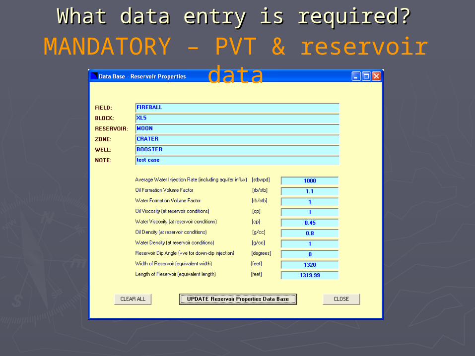
What data entry is required?What data entry is required?
MANDATORY – PVT & reservoir data
What data entry is required?What data entry is required?
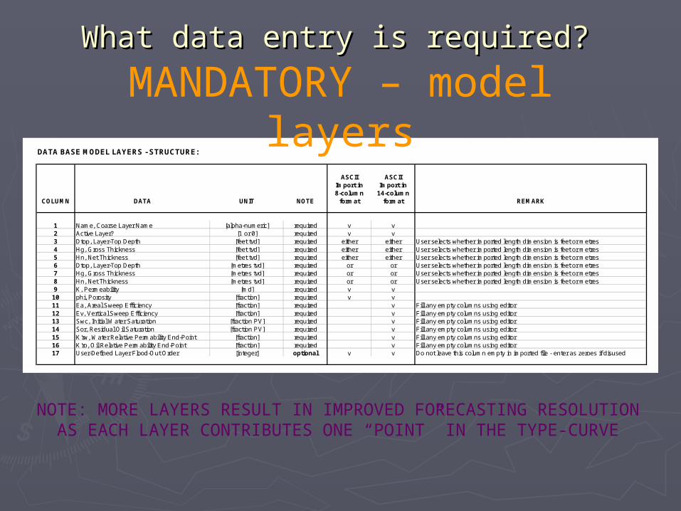
DATA BASE MODEL LAYERS - STRUCTURE:
ASCII ASCIIImport in Import in8-column 14-column
COLUMN DATA UNIT NOTE format format REMARK
1 Name, Coarse Layer Name [alpha-numeric] required v v2 Active Layer? [1 or 0] required v v3 Dtop, Layer-Top Depth [feet tvd] required either either User selects whether imported length dimension is feet or metres4 Hg, Gross Thickness [feet tvd] required either either User selects whether imported length dimension is feet or metres5 Hn, Net Thickness [feet tvd] required either either User selects whether imported length dimension is feet or metres6 Dtop, Layer-Top Depth [metres tvd] required or or User selects whether imported length dimension is feet or metres7 Hg, Gross Thickness [metres tvd] required or or User selects whether imported length dimension is feet or metres8 Hn, Net Thickness [metres tvd] required or or User selects whether imported length dimension is feet or metres9 K, Permeability [md] required v v
10 phi, Porosity [fraction] required v v11 Ea, Areal Sweep Efficiency [fraction] required v Fill any empty columns using editor12 Ev, Vertical Sweep Efficiency [fraction] required v Fill any empty columns using editor13 Swc, Initial Water Saturation [fraction PV] required v Fill any empty columns using editor14 Sor, Residual Oil Saturation [fraction PV] required v Fill any empty columns using editor15 K'rw, Water Relative Permability End-Point [fraction] required v Fill any empty columns using editor16 K'ro, Oil Relative Permability End-Point [fraction] required v Fill any empty columns using editor17 User-Defined Layer Flood-Out Order [integer] optional v v Do not leave this column empty in imported file - enter as zeroes if disused
MANDATORY – model layers
NOTE: MORE LAYERS RESULT IN IMPROVED FORECASTING RESOLUTION AS EACH LAYER CONTRIBUTES ONE “POINT” IN THE TYPE-CURVE

What data entry is required?What data entry is required?
MANDATORY – production profiles
DATA BASE PRODUCTION PROFILES - STRUCTURE:
ASCII ASCIIImport in Import in7-column 18-column
COLUMN DATA UNIT1 NOTE format format REMARK
1 DATE {must be daily time steps} [dd/mm/yyyy] required v v May be imported or set-up using the editor; MUST BE DAILY TIME STEPS2 COPR, Constraining Oil Production Rate [stbopd] required v v May be imported or set-up using the editor3 CWPR, Constraining Water Production Rate [stbwpd] required v v May be imported or set-up using the editor4 CLPR, Constraining Liquid Production Rate [stblpd] required v v May be imported or set-up using the editor5 AWCR, Actual Water-Cut Ratio [fraction] required v v May be imported or set-up using the editor6 AWOR, Actual Water/Oil Ratio [fraction] optional v v May be imported or set-up using the editor; set column to zero if disused7 CWIR, Constraining Water Injection Rate [stbwpd] required v v May be imported or set-up using the editor8 MOPR, Model Oil Production Rate [stbopd] forecast v Calculated by the Forward Model Multi-Rate Forecast9 MWPR, Model Water Production Rate [stbwpd] forecast v Calculated by the Forward Model Multi-Rate Forecast10 MLPR, Model Liquid Production Rate [stblpd] forecast v Calculated by the Forward Model Multi-Rate Forecast11 MWCR, Model Water-Cut Ratio [fraction] forecast v Calculated by the Forward Model Multi-Rate Forecast12 MWOR, Model Water/Oil Ratio [fraction] forecast v Calculated by the Forward Model Multi-Rate Forecast13 MWIR, Model Water Injection Rate [stbwpd] forecast v Calculated by the Forward Model Multi-Rate Forecast14 MOPC, Model Oil Production Cumulative [stbo] forecast v Calculated by the Forward Model Multi-Rate Forecast15 MORR, Model Oil Recovery Ratio (Factor) [fraction] forecast v Calculated by the Forward Model Multi-Rate Forecast16 MWPC, Model Water Production Cumulative [stbw] forecast v Calculated by the Forward Model Multi-Rate Forecast17 MLPC, Model Liquid Production Cumulative [stbl] forecast v Calculated by the Forward Model Multi-Rate Forecast18 MWIC, Model Water Injection Cumulative [stbw] forecast v Calculated by the Forward Model Multi-Rate Forecast
NOTE 1 - Volume Units available, for import and display, are: stb, scf and scmNOTE 2 - Columnised data entry starts at row two (2) of the imported ascii data fileNOTE 3 - Row one (1) of the imported file must contain the Title of the Production Profile [alpha-numeric]NOTE 4 - Flood-Out requires daily time steps
What data entry is required?What data entry is required?
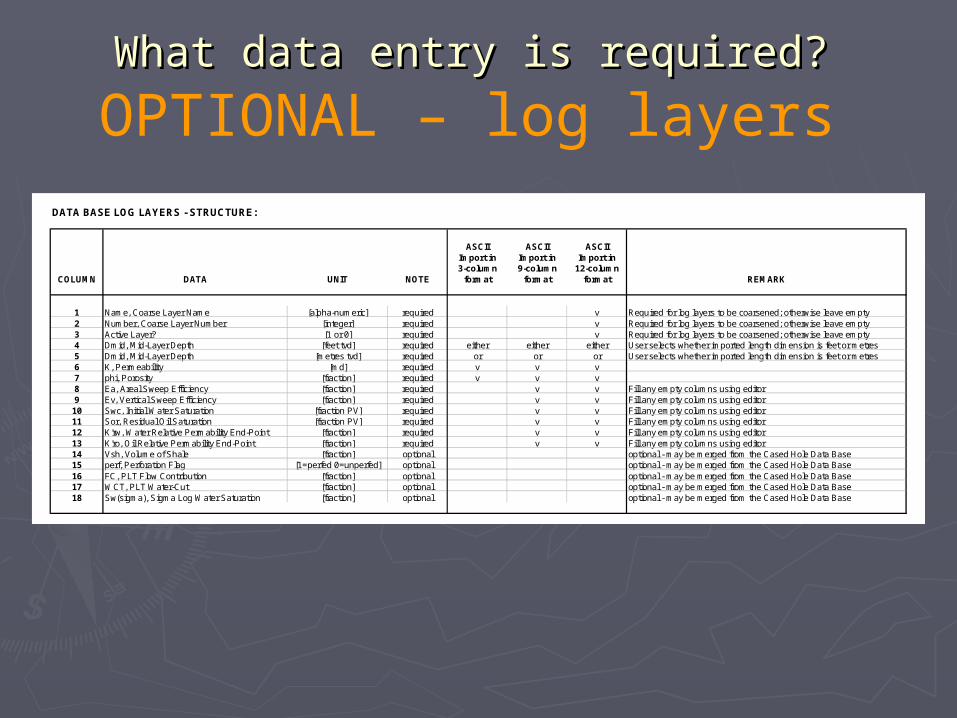
DATA BASE LOG LAYERS - STRUCTURE:
ASCII ASCII ASCIIImport in Import in Import in3-column 9-column 12-column
COLUMN DATA UNIT NOTE format format format REMARK
1 Name, Coarse Layer Name [alpha-numeric] required v Required for log layers to be coarsened; otherwise leave empty2 Number, Coarse Layer Number [integer] required v Required for log layers to be coarsened; otherwise leave empty3 Active Layer? [1 or 0] required v Required for log layers to be coarsened; otherwise leave empty4 Dmid, Mid-Layer Depth [feet tvd] required either either either User selects whether imported length dimension is feet or metres5 Dmid, Mid-Layer Depth [metres tvd] required or or or User selects whether imported length dimension is feet or metres6 K, Permeability [md] required v v v7 phi, Porosity [fraction] required v v v8 Ea, Areal Sweep Efficiency [fraction] required v v Fill any empty columns using editor9 Ev, Vertical Sweep Efficiency [fraction] required v v Fill any empty columns using editor10 Swc, Initial Water Saturation [fraction PV] required v v Fill any empty columns using editor11 Sor, Residual Oil Saturation [fraction PV] required v v Fill any empty columns using editor12 K'rw, Water Relative Permability End-Point [fraction] required v v Fill any empty columns using editor13 K'ro, Oil Relative Permability End-Point [fraction] required v v Fill any empty columns using editor14 Vsh, Volume of Shale [fraction] optional optional - may be merged from the Cased Hole Data Base15 perf, Perforation Flag [1=perfed 0=unperfed] optional optional - may be merged from the Cased Hole Data Base16 FC, PLT Flow Contribution [fraction] optional optional - may be merged from the Cased Hole Data Base17 WCT, PLT Water-Cut [fraction] optional optional - may be merged from the Cased Hole Data Base18 Sw(sigma), Sigma Log Water Saturation [fraction] optional optional - may be merged from the Cased Hole Data Base
OPTIONAL – log layers

The flood-out ProcessThe flood-out Process01 Import fine resolution log data and define coarse model layers -
02 Create coarse model layers -

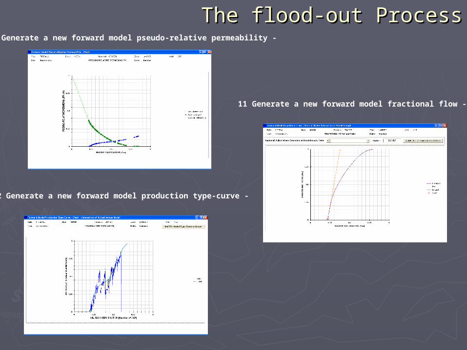
The flood-out ProcessThe flood-out Process03 Generate forward model pseudo-relative permeability -
04 Generate forward model fractional flow -

The flood-out ProcessThe flood-out Process05 Generate the forward model production type-curve -
06 View the first-pass water-cut history match (match needs improvement) -
First-pass: Poor history match!
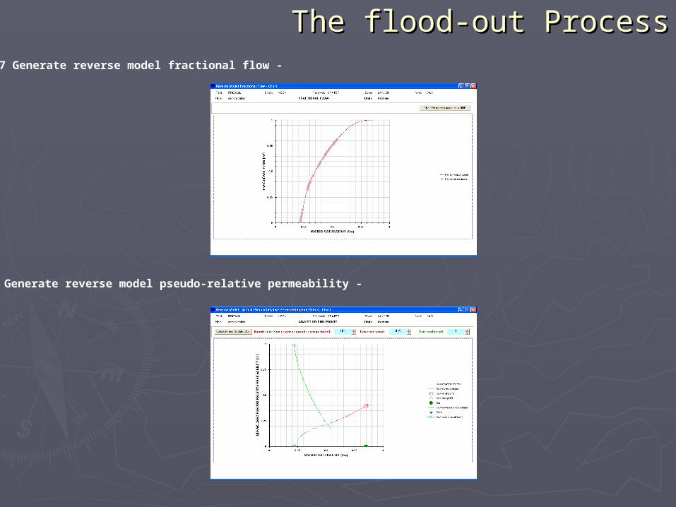
The flood-out ProcessThe flood-out Process07 Generate reverse model fractional flow -
08 Generate reverse model pseudo-relative permeability -
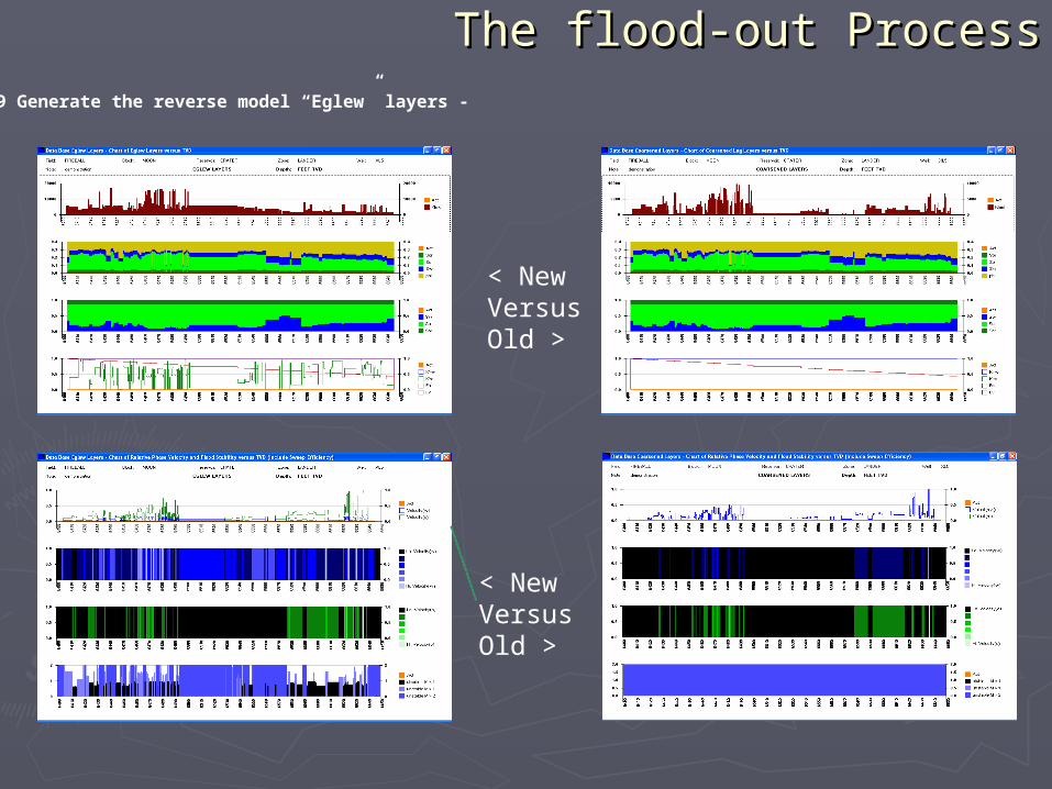
The flood-out ProcessThe flood-out Process09 Generate the reverse model “Eglew” layers -
< New Versus Old >
< New Versus Old >
The flood-out ProcessThe flood-out Process
11 Generate a new forward model fractional flow -
12 Generate a new forward model production type-curve -
10 Generate a new forward model pseudo-relative permeability -

The flood-out ProcessThe flood-out Process
13 An improved water-cut history match results from importation of the reverse model into the forward model -
14 An optimised production and injection forecast can now be generated within system’s constraints -
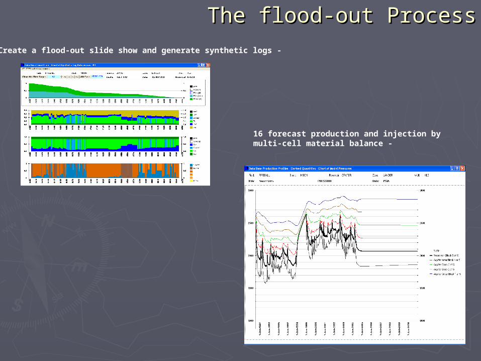
The flood-out ProcessThe flood-out Process15 Create a flood-out slide show and generate synthetic logs -
16 forecast production and injection bymulti-cell material balance -

Dykstra-Parsons’ Water Flood Dykstra-Parsons’ Water Flood Theory adapted to Chemical Flood Theory adapted to Chemical Flood
ModelingModeling
DYKSTRA-PARSONS’ THEORY:DYKSTRA-PARSONS’ THEORY:(a) is applicable for all mobility ratios(a) is applicable for all mobility ratios(b) assumes layers flood-out in flow-(b) assumes layers flood-out in flow-
velocity ordervelocity order(c) layer cross-flow does not occur(c) layer cross-flow does not occur

Polymer Flood Model: How Polymer Flood Model: How does it work?does it work?
Dykstra-Parsons’ theory is employed to accomplish the Dykstra-Parsons’ theory is employed to accomplish the following (at each time step) for a user-specified set of following (at each time step) for a user-specified set of Model Layers:Model Layers:
1.1. Determine relative flood-frontal advancement for each layerDetermine relative flood-frontal advancement for each layer
2.2. Generate a type-curve (Oil Recovery Factor versus Water-Generate a type-curve (Oil Recovery Factor versus Water-cut), which is interpolated by the forecasting optimiser cut), which is interpolated by the forecasting optimiser
3.3. Once polymer is introduced, layer permeability is altered Once polymer is introduced, layer permeability is altered according to resistance factor expressed as a function of in-according to resistance factor expressed as a function of in-situ (i.e. reservoir) polymer concentration (ppm)situ (i.e. reservoir) polymer concentration (ppm)
4.4. Highly-permeable layers accept larger water injection Highly-permeable layers accept larger water injection volumes, and consequently polymer concentration builds-volumes, and consequently polymer concentration builds-up preferentially in these layers. This stabilises the flood, or up preferentially in these layers. This stabilises the flood, or invokes profile conformance.invokes profile conformance.

Dykstra-Parsons’ Water Flood Dykstra-Parsons’ Water Flood Theory adapted to Chemical Theory adapted to Chemical
Flood ModellingFlood Modelling
-10
0
10
20
30
40
50
60
70
0 200 400 600 800 1000 1200 1400 1600
measured data
F(X)-3S = 99.7% of data
F(X)-2S = 95.5% of data
F(X)-1S = 64% of data
F(X) = polynomial of best fit
F(X)+1S = 64% of data
F(X)+2S = 95.5% of data
F(X)+3S = 99.7% of data
Res
.Fac
tor
Poly.Conc.
A spreadsheet employing non-linear regression automatically finds a cubic polynomial of best-
fit to tabulated data
A B C D
Y = 3.54E-08 X3 + -3.49E-05 X2 + 0.014775 X + 0.858221
HOW DOES IT WORK?
High K Layers build-up the highest polymer concentration, which alters layer flow-velocity order and invokes profile conformance.
Note: THIS CURVE APPLIES FOR A
FIXED INJECTION RATE
IN-SITU POLYMER CONCENTRAION
RESISTANCE FACTOR

Polymer Gel Model Polymer Gel Model Output and ForecastsOutput and Forecasts
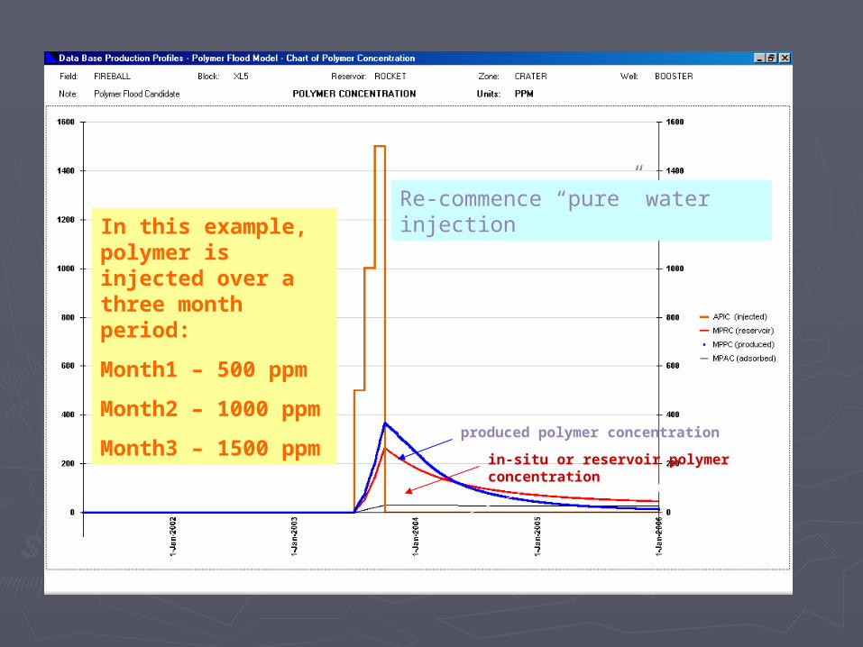
In this example, polymer is injected over a three month period:
Month1 – 500 ppm
Month2 – 1000 ppm
Month3 – 1500 ppm
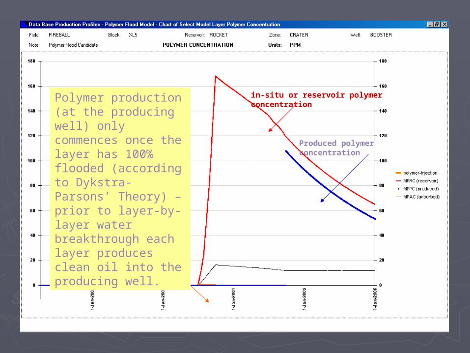
in-situ or reservoir polymer concentration
produced polymer concentration
Re-commence “pure” water injection
adsorbed polymer concentration
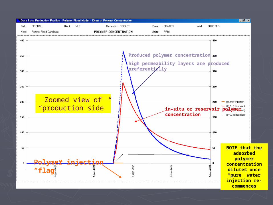
Produced polymer concentration –
high permeability layers are produced preferentially
in-situ or reservoir polymer concentration
Polymer injection “flag”
adsorbed polymer concentration
Zoomed view of “production side”
NOTE that the adsorbed polymer
concentration dilutes once “pure” water injection re-commences
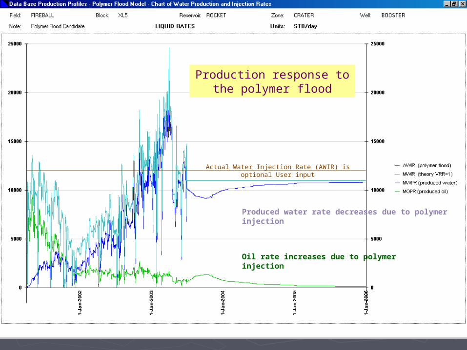
Produced water rate decreases due to polymer injection
Oil rate increases due to polymer injection
Production response to the polymer flood
Actual Water Injection Rate (AWIR) is optional User input

Once polymer injection ceases, displaced by “pure” water injection, the resistance factor decreases. Adsorbed polymer is entrapped in order to model residual resistance.
Resistance Factor >
Re-commence “pure” water injection
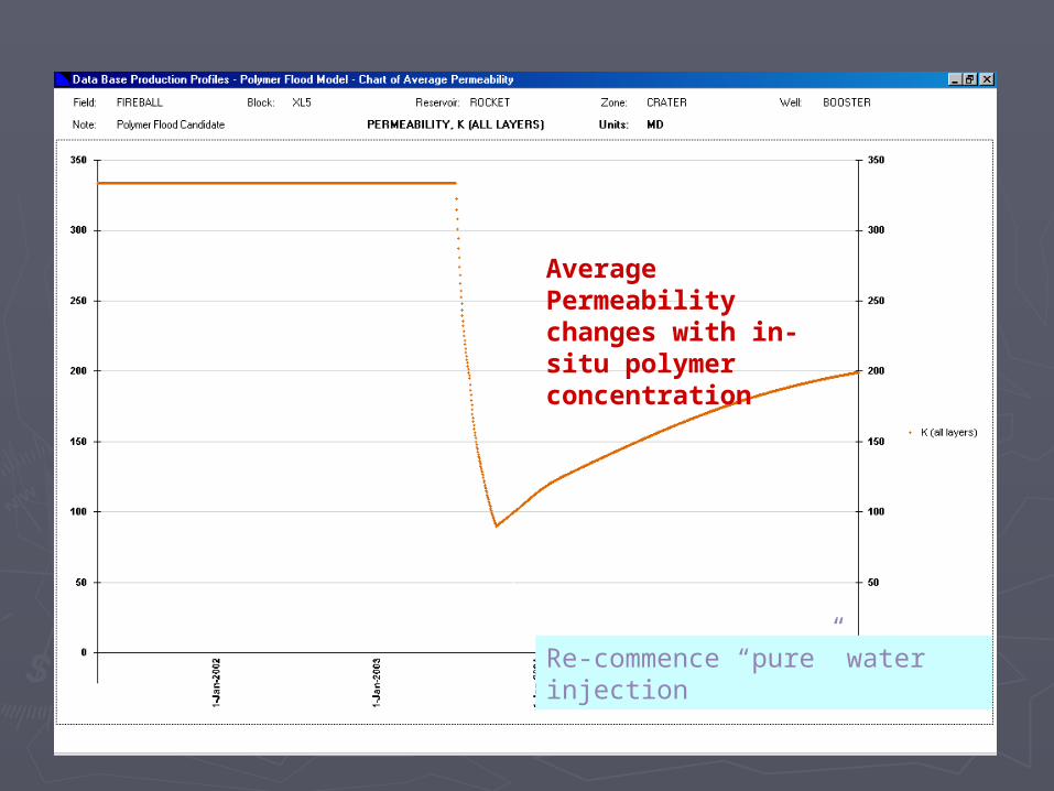
Average Permeability changes with in-situ polymer concentration
Re-commence “pure” water injection

Maximum permeability of all model layers
Average permeability and standard deviation of model layer permeability
NOTE: standard deviation of K is a measure of profile conformance, enhanced by the injection of polymer (i.e. Std Dev. decreases once polymer is introduced)
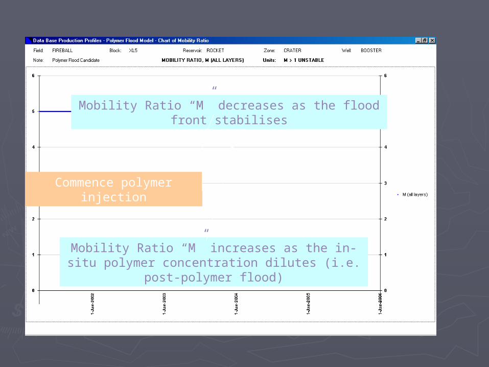
Commence polymer injection
Mobility Ratio “M” decreases as the flood front stabilises
Mobility Ratio “M” increases as the in-situ polymer concentration dilutes (i.e. post-polymer flood)
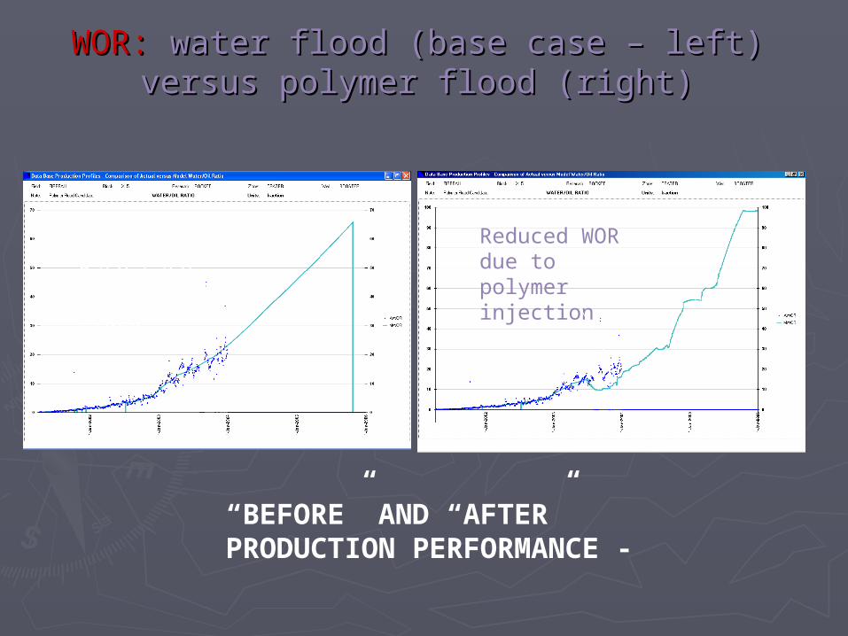
WOR:WOR: water flood (base case – left) versus water flood (base case – left) versus polymer flood (right)polymer flood (right)
“BEFORE” AND “AFTER” PRODUCTION PERFORMANCE -
Reduced WOR due to polymer injection
Base Case Water-flood

Oil Rate:Oil Rate: water flood (base case – left) water flood (base case – left) versus polymer flood (right)versus polymer flood (right)
“BEFORE” AND “AFTER” PRODUCTION PERFORMANCE -
Oil rate uplift due to polymer injection
Base Case Water-flood

The Polymer Flood Model allows the User to track the performance of any Model Layer – here and in the following slides layer # 20 performance is shown.
Dykstra-Parsons relative layer water flood penetration distance (versus time) for layer # 20
Layer # 20 100% flooded
Produced polymer concentration
in-situ or reservoir polymer concentration
Polymer injection “flag” adsorbed polymer concentration
Polymer production (at the producing well) only commences once the layer has 100% flooded (according to Dykstra-Parsons’ Theory) – prior to layer-by-layer water breakthrough each layer produces clean oil into the producing well.

Layer # 20 Oil Rate increases as the model allocates more Water Injection to layer # 20 (i.e. following the commencement of polymer injection)
Layer # 20 100% flooded
Water breakthrough at producer for layer # 20

Once polymer injection ceases, displaced by “pure” water injection, the resistance factor decreases. Adsorbed polymer is entrapped in order to model residual resistance.
Layer # 20 Resistance Factor >
Re-commence “pure” water injection
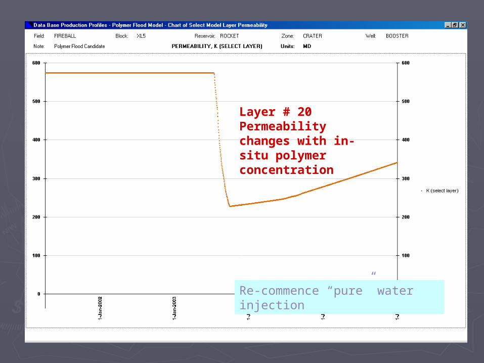
Layer # 20 Permeability changes with in-situ polymer concentration
Re-commence “pure” water injection

Simulation of Polymer Simulation of Polymer Gel Injection Well Gel Injection Well
TreatmentsTreatments
Chuck NormanChuck Norman
Tiorco, Inc. Tiorco, Inc.
Tiorco de ArgentinaTiorco de Argentina