simulation of fracture behavior in particle-dispersed ceramic composites
TRANSCRIPT

Pergamon Engineering Fracture Mechanics Vol. 59, No. 3, pp. 289-303, 1998 © 1998 Elsevier Science Ltd. All rights reserved
Printed in Great Britain PII : S0013-7944(97)00131-8 0013-7944/98 $19.00 + 0.00
S I M U L A T I O N O F F R A C T U R E B E H A V I O R I N P A R T I C L E -
D I S P E R S E D C E R A M I C C O M P O S I T E S
BYUNG-NAM KIMf MAKOTO WATANABE MANABU ENOKI and TERUO KISHI
Research Center for Advanced Science and Technology, The University of Tokyo, 4-6-1 Komaba, Meguro-ku, Tokyo 153, Japan
Abstract--A two-dimensional crack path is simulated in particle-dispersed ceramic composites along with the related variation of fracture resistance with crack extension. The direction of crack propa- gation is influenced by the geometrical crack shape and localized residual stresses due to the thermal expansion mismatch between particle and matrix. The simulation is conducted for both a SiC matrix composite dispersed with A1203 particles and an A1203 matrix composite dispersed with SiC particles, under an assumption of hard particles. In the SiC-AI203~ ~ composite a crack propagating near the
P . .~ . .
A1203 particles has a tendency to be repelled due to the residual tensile stress in the radial direction around the particles, and the entire fracture resistance shows a lower value than the matrix toughness. In the Al203-SiC<p) composite, a crack is attracted by the SiC particles. Due to the residual compres- sive stress in the radial direction around the SiC particles, the fracture resistance increases up to five times the matrix toughness when the crack propagates along the interface. The apparent fracture resist- ance of the AIzO3-SiC(p I composite shows a higher value than the matrix toughness, and an increasing R-curve behavior with crack extension is predicted. The approximately estimated two-dimensional frac- ture toughness of the AI203-SiCcp ) composite increases with the volume fraction of particles, while it decreases in the SiC-A1203{p) composite. © 1998 Elsevier Science Ltd
Keywords--crack deflection, fracture resistance, residual stress, interface, body force method.
1. INTRODUCTION
RECENTLY, TWO-DIMENSIONAL crack propagation behavior was simulated in an A1 metal matrix composite reinforced with SiC short fibers, by taking into account the microcracking process at the interfaces and the interaction with a main crack [1]. Although several analyses and simu- lations were carried out under microcrack interaction [2-4], the commonly employed assumption was a self-similar crack propagation. It is probably the first trial to simulate a continuously deflecting crack path under the microcrack interaction by using fracture-mechanical treatments. The simulated crack path and the related variation of stress intensity factors represent a strong dependence on the presence of microcracks. However, the simulation does not describe a detailed method for calculating stress intensities at the tip of the multiple deflected crack, and shows some unreasonable results, for example, crack extension under minus mode I stress inten- sity, and abrupt changes of crack path near the microcracks.
Similar simulations of continuous crack paths were carried out for two-dimensional poly- crystals by one of the authors [5]. By allowing the ratio of the grain boundary toughness to grain toughness to vary, intergranular and transgranular crack paths were simulated along with the variation of fracture resistance with crack extension. In the simulation, by assuming a homo- geneous continuum, the stress intensity factors at the crack tip were calculated numerically only from the geometrical shape of cracks by the body force method (BFM). The predicted depen- dence of the fracture toughness and the transgranular fracture ratio on the grain boundary toughness represented good agreement with the analytical results [5].
In the case of particle-dispersed brittle composites, three-dimensional simulation of crack growth behavior was carried out around the dispersed particles by perturbation analysis [6, 7] and by following the boundary element method [8]. When the fracture toughness of the particle is higher than that of the matrix, crack growth is retarded by the particle, and crack trapping occurs. The simulation shows that highly applied stress intensities are required for the trapped crack to escape from the particles. This type of toughening mechanism was also analyzed by the
fAuthor to whom all correspondence should be addressed.
289

290 B.-N. K1M e t al.
crack-pinning model [9]. However, in the three-dimensional simulation, it was assumed that a crack grows in an in-plane manner, resulting in an inevitable penetration of the crack into the impinged particles. Localized stresses around the particles were also neglected, which can be generated from the elastic and/or thermal mismatch between the particle and the matrix in the composites.
Provided that the particles of different mechanical properties are dispersed in polycrystals or monolithics, the stress intensity factors at the crack tip would be influenced by the localized residual stresses. Depending on the localized stresses, a crack path would be changed to be attracted or repelled by the particles. When the particles have a higher thermal expansion and higher elastic modulus, a crack has a tendency to be repelled and propagate around the particles [10]. However, such crack-particle interaction has been understood experimentally and phenomenologically only by considering the state of the localized stresses around the particle. The attracting or repelling processes of the crack have not been examined systematically, nor has the critical condition of crack-trapping under the crack-localized stress interaction.
In this study, a two-dimensional continuous crack path is simulated under the macroscopi- cally mode I plane stress condition for brittle composites dispersed with spherical particles. The interaction between the crack and the particle is investigated as a function of the volume frac- tion of the dispersed particles. In order to avoid complicated problems arising from the differ- ence of the elastic properties between the matrix and the particle, stress intensity factors are calculated under the assumption of an isotropic continuum of the composites. The material properties are used only for the determination of the residual hydrostatic stress within a particle. The simulation is carried out for both cases of higher and lower thermal expansion of the par- ticle than that of the matrix: a SiC matrix composite dispersed with A1203 particles, and an A1203 matrix composite dispersed with SiC particles.
2. DETERMINATION OF CRACK PATH UNDER RESIDUAL STRESS FIELDS
Localized residual stresses around a particle influence the crack path by altering the crack tip stress state. In two-dimensional composites dispersed with spherical particles, the residual tangential stress ao and radial stress ar in the matrix due to the thermal expansion mismatch between the matrix and the particle are given by[11]
R 2 --0- 0 = O" r = O'i-~- , (la)
ai = 2flp/ lm[(1 q- I)m)~gm -- (1 -q- Vp)0~p]AT, ( l b )
[#p + (1 - 2Vp)pm ]
where tip,m, Pp,m and (Xp, m are the shear modulus, Poisson's ratio and thermal expansion coeffi- cient for the particle and the matrix, respectively, A T is the temperature difference, R is the par- ticle radius, and r is the distance from the center of the particle. The stress within the spherical particle is essentially hydrostatic and given by o" i of eq. (lb). According to the sign of (~p--0~rn), residual tensile or compressive stress is generated by the temperature change.
Stress intensity factors at the tip of the multiple deflected crack under both residual and external stress fields can be obtained numerically by the BFM, which was developed by Nisitani et al. [12]. The BFM is a kind of simplified boundary element method, giving highly accurate sol- utions in a short time span, especially for a two-dimensional elastic problem. For the calculation of stress intensity factors by the BFM, the coordinates describing the geometrical shape of the corresponding crack and the applied loading condition are required as input-data. The exter- nally applied stress intensity, Ka, is represented as a function of the applied stress, aa, that is, Ka = aa K', where K' (actually calculated) is the stress intensity factor at the crack tip corre- sponding to the unit applied stress under uniaxial tension, with a unit of m 1/2.
Since both the residual and the applied stress intensity factors, Kr and Ka, contribute to the crack tip stress fields independently, the two quantities are calculated independently by the BFM. In order to include the residual stress effects, the particles are replaced with a void of 16 edges, in which the interfacial pressure of ~i acts. The number of edges of the void for the BFM

Fracture behavior in ceramic composites 291
r~
500
400
300
200
100
IR
.. tic,o i i I I I i i
circular particle • 8-edge particle • 16-edge particle
n I I
0 2 4 6 8 10 12 14 16
Distance, r/R
Fig. 1. Comparison of residual stresses in the radial direction around the SiC particle in the A1203 matrix. Residual stress for circular particle is obtained by eq. (1), and those for eight- and 16-edge par-
ticles are calculated numerically by the body force method.
calculation is not significant in representing the residual stress fields in the matrix when it is greater than eight, as illustrated in Fig. 1. The difference between the theoretical [by eq. (la)] and the calculated (by the BFM) residual stress becomes considerable at r < 1.05R for the 16- edge particle, because the originally circular interface is described by the 16 discrete straight lines. However, in the range of r> 1.05R, the residual stress distribution in the matrix can be represented with high accuracy by introducing a pressurized void of 16 edges. The difference between the calculated and the theoretical ar at r = 1.05R is less than 5%.
Kr is obtained with respect to the pressurized voids representing the dispersed particles. However, in the unlikely case of Ka, Kr is obtained as an absolute value because the cri is an ab- solute one. Then by the rule of superposition, as described schematically in Fig. 2, the total
°aT l particle
matrix
crack / K r + K a
Fig. 2. Total stress intensity factors at crack tip are given by the superposition of thermal stress intensity Kr on mechanical stress intensity Ka, which are obtained by the body force method,
respectively.

292 B.-N. KIM et al.
stress intensities at the crack tip for each mode, KI and Kn, are given by
KI = Klr +aaK;, (2a)
KII = KIIr + o'aKll, (2b)
as a function of aa, which have to be determined at critical state. When the deflected portion of the crack is infinitesimally small with respect to the total
crack length, the stress intensity factors at the deflected crack tip, k I and kn, can be written in terms of Kl and Kit. First-order solutions yield[13, 14]
ki = fll(8)Ki +)~1 (8)KII, (3a)
/II =fl2(8)KI +f22(8)Kn, (3b)
where 8 is the deflection angle as described in Fig. 3, and Jij{8) is an angular function analogous to the angular dependence of the normal and shear stresses in the near-tip field.
The extension of the deflected crack is a mixed-mode fracture. Although several different criteria have been proposed for the mixed-mode fracture, the most commonly used criteria are the maximum tangential stress criterion [15], minimum strain energy density criterion [16], and maximum energy release rate criterion [17, 18]. In this simulation, the maximum energy release rate criterion is employed because it is consistent with the original energy balance concept of Griffith. Specifically, among the proposed criteria of the maximum energy release rate, Nuismer's criterion [18] is employed to determine the deflecting direction mainly due to the simple expression. Then, the strain energy release rate, G, is represented as
G = 1 (ki2 + ki2l), (4) E
where E is the Young modulus for plane stress condition. From eqs (2)-(4), the energy release rate in the 0-direction is obtained as
1 G = ~ f(tra, 8). (5)
Since K' is dependent only on the geometrical crack shape, and Kr on both the crack shape and the material properties (ai) under the assumption of an isotropic continuum of the composites, G of eq. (5) becomes a second-order equation of aa for the given situation of the crack shape and the particle distribution. Solving the equation of G =Gcm for respective &directions in the range of -re/2 < 8 ~< re/2, the necessary applied stress o a for each direction 8 is calculated. Figure 4 shows an example of the variation of tra with respect to 8. Among the obtained pairs of 8 and O'a, the crack will extend in the direction of the lowest o a. Then, the direction of crack propa- gation, 8c, and the critical applied stress, O-ca , are determined at each step of the crack extension. Here, Gcm is the critical energy release rate represented as Gcm = K2cm/E, where gem is the frac- ture toughness of the matrix. From the aca and the projected crack length, 2a, on the normal plane to the loading axis, the apparent fracture resistance, Kea, is obtained from aca (x / ' ~ . The extended length of the crack by one step advance is taken to be a half of the particle radius. The continuous crack path is simulated by repeating the above procedures.
One problem caused in the simulation of the continuous fracture path in the composites is the crack propagation at interfaces. When a crack impinges on the particle (or the interface),
k I, kli
K I ~ _ _ .
Fig. 3. Stress intensity factors at deflected crack tip are dependent on those at main crack tip and deflection angle. The direction of crack path is determined by the stress intensity factors at main
crack tip.

Fracture behavior in ceramic composites 293
1000
~_. 800
8
~ 600
~ 400
N :.~ 2oo
0 -90 90
i . . . . . . .
"°ca 1 i i
, i 0 c . . , , , ,
-60 -30 0 30 60
Deflecting direction, 0/Deg.
Fig. 4. Critical applied stress for each deflecting direction of crack tip under the mixed mode condition of Kit=0.656 MPa~'-m, Kllr=l.93 MPa~/m, K ' l=6 .49x10 3 x/m, K ' H = - - 4 - 6 9 x I 0 -~ x/m and
Kcm = 3.5 MPa x/-m. The crack deflects into the direction o f - 5 0 ° at trca = 230 MPa.
there occurs a competition of the crack path between penetration and deflection[19]. Whether the crack will pass through the particle or be deflected into the interface depends on the stress intensity factors, the fracture toughness of both the particle and the interface, and the imping- ing angle on the interface. However, as mentioned above, when the crack tip is very close to the interface, the numerical errors in both stress distribution and K' become significant, and the exact crack path cannot be determined, resulting in an abrupt change of crack path near the particle. For this reason, an imaginary interface is assumed to exist near the actual inter- face, and crack propagation impinged on the particle occurs along the imaginary interface. The imaginary interface is positioned at r = 1.05R, where the residual stress distribution shows relatively good agreement between the numerical and the analytical results. Now, the fracture toughness of the interface is assumed to be simply the same as that of the matrix. By introducing the imaginary interface, the simulated crack path impinged on the particles becomes quite smoother.
In addition, the particles are assumed to be so strong that a crack does not propagate into them. In some particle-dispersed ceramic composites [20,21], the failure of particles is observed frequently due to strong interfaces compared with the particle itself. However, the failure of particles results in complicated stress fields in the matrix around the particle, and an appropriate method to describe the stress fields has not yet been found. Hence, the par- ticles are assumed to be hard in the present simulation in order to avoid this complication. Fortunately, in the case of both the AlzO3-SiC(p)[22] and SiC-A1203~p~ composites [23], the crack propagation along the interfaces was observed as a primary mechanism rather than a failure of particles.
3. RESULTS AND DISCUSSION
In determining Kr for the given crack shape and particle distribution, the material proper- ties have to be given in order to calculate the residual stress at interfaces, o" i of eq. (1). In this simulation, both the SiC matrix-A1203 particle and the A1203 matrix-SiC particle systems are selected as the components of a model composite, and the respective material properties of SiC and A1203 are represented in Table 1. Providing -1200°C as the value of A T in the A1203- SiC~p) composite, a tensile stress of about 966 MPa is generated at the interface in the circumfer- ential direction, which decreases rapidly with increasing distance, as illustrated in Fig. 1. The value of Kr at the crack tip is calculated by applying a hydrostatic pressure (O'i) of 966 MPa in the 16-edge void.

294 B.-N. KIM et al.
Table 1. Material properties of particle and matrix
Material property SiC AI203
Thermal expansion coefficient 5.12 x 10⁻⁶°C-I 8.1 x 10⁻⁶°C -I Shear modulus 180 GPa 162 GPa Poisson's ratio 0.25 0.235 Fracture toughness 3.5 MPa ~ 1.5 MPa x /~
3.1. Crack propagation in the composite of the SiC matrix-Al203 particle
In the composites of ~p > ~m, since residual tensile stress is generated around the particles in the radial direction, a crack propagating near the particles has a tendency to be repelled. The deviated crack path by the repelling residual stress is recovered gradually after passing the loca- lized stress fields. However, in the present SiC-A1203(p) composite, when the distance between the crack and the particle in the loading direction, y, is smaller than about 0.2R, the crack impinges on the particle despite the repelling stress. Figure 5(a) shows the simulated crack path around the spherical A1203 particle for various Yi, where yi is the initial distance of the crack tip from the center of the particle in the loading direction. The initial crack is flat with its plane normal to the loading axis, indicating a pure mode I condition prior to growth. The length of
0
.2
.~,
-4
-6
[ • I • I I I ! I I • I
(a)
. . . . . - 4 - ' ~ ' ' ' ( ) ' * . . . . . . 2 4
Distance, x/R
~2
1
' I '
(b)
• ! • !
-4
I | . I I I ' I ~ I | I I
I I
matrix ', particle', matrix I I
I , I , ~ I • I • I •
-2 0 2 4
Distance, ~
Fig. 5. (a) Simulated crack path in the SiC matrix around the A1203 particle, and (b) the related vari- ation of apparent fracture resistance with crack extension. Crack propagates from left to right.

Fracture behavior in ceramic composites 295
the initial crack is 15R, and the position of the right crack tip is x = - 5R, where x is the dis- tance from the center of the particle in the normal direction to the loading axis.
The fracture resistance, Kca, increases when the crack approaches the particle, as shown in Fig. 5(b), since residual compressive stress exists in the circumferential direction around the par- ticle. When the residual stress acts as an opening-mode for the crack tip which passed the par- ticle, the Kca decreases. A fracture at the interfaces is an extreme case, as shown in Fig. 5(b), where the gca becomes zero due to the high residual tensile stress in the radial direction. Although the crack is assumed to propagate along the imaginary interface at r = 1.05R in this simulation, the zero resistance during the interface propagation would be identical to the case of the fracture along the original interface, because the residual tensile stress increases with decreas- ing r. If the residual tensile stress in the radial direction becomes smaller, the fracture resistance during the interface fracture would increase. However, in many composites, since the fracture toughness of the interface is lower than that of the matrix, the Kr of opening-mode at the inter- faces makes a crack extend easily by the interaction with K' in the composites of higher thermal expansion of particles.
Crack path was also investigated in the composite of randomly distributed particles. Spherical particles of 5-30% were introduced according to the Poisson distribution in the range of 0 < x/R < 40 and -10 < y/R < 10. The initial crack shape is the same as the previous one, and the initial position of the right crack tip is x = - 5R and y = OR. Figure 6(a) represents the simulated crack path in the SiC matrix composite dispersed with 5% A1203 particles. The crack propagates between the particles, and it is found that the crack hardly impinges on the particles.
G
.z ¢2
10
5
0
-5
-10 -10
(a) . . . . I " 0 °
O0 0
• O 0 • • •
0 0
0
. . . . I . . . . I . . . . t . . . .
0 10 20 30
Distance, x/R
40
. . . . I . . . . I . . . . I . . . . I . . . .
(b)
l ! i a | I l I . . . . i I I I i I ! | | i
-10 0 10 20 30
Distance, x/R
40
Fig. 6. (a) Simulated crack path, and (b) the related variation of apparent fracture resistance with crack extension in the SiC composite dispersed with 5% A1203 particles. Crack propagates from left to right.

296 B.-N. KIM et al.
In the unlikely case of Yi = 0 in Fig. 5(a), the crack path is deviated by the repelling stress of the randomly distributed particles, far before the crack approaches the particles. Only when the crack passes through the highly concentrated region of the particles, as in the composite of more than 20% particles, an impingement occurs. The related variation of Kca is shown in Fig. 6(b). As in Fig. 5(b), gca increases initially as the crack approaches the region of the par- ticle distribution. However, once the crack enters the particle-dispersed region, the Kca decreases below the K~m, and continues to have a lower value.
In the composites of higher thermal expansion of particles, residual stresses act as an open- ing-mode for the crack, when the particle locates above and below the crack surface, while act- ing as a closing-mode in front of the crack tip. The two modes exist at all propagating steps in the composites with randomly distributed particles. However, with crack extension, the opening- mode begins to prevail and the crack propagates between the particles as in Fig. 6(a). As illus- trated in Fig. 5(b), the reduction of the KCa when the crack tip locates below the particle is greater than the enhancement when the crack approaches the particle.
On the other hand, it was reported that once a crack starts to grow, the direction of propa- gation is such that Kn = 0 as long as it grows with a continuously turning tangent[24]. However, in the present simulation of the continuously deflecting crack path, the criterion of maximum energy release rate was employed despite the relatively long growth. As mentioned above, the crack-extending length was taken to be 0.5R by one-step advance, indicating somewhat discrete propagation. Too small an extending length by one-step advance takes too much time for the crack to grow up to about 30R, along with considerable error. Equation (3) is also valid only when the deflected portion is infinitesimally small with respect to the length of the undeflected crack. A straight crack tip portion, 0.5R long in this study, is considered to be necessary for the validity of eq. (3). Thus, the condition of continuously turning crack growth is not fulfilled for the strict application of the criterion of kn = 0.
In addition, the criterion of kn = 0 gives only the direction of crack propagation. Since the direction of kn = 0 is dependent on the value of o" a because of the existence of a constant term of Kr in eq. (2), additional criterion is required, for example, kt = K~m or G = Gcm, in order to determine the external fracture stress Crca. However, the directions of both kn = 0 and G = Gcm show only a slight difference in a two-dimensional case. The difference was less than 1 ° during the present simulation. In the direction of G = Gcm, the component of kn is nearly zero at all the advancing steps, which is a basic idea of Goldstein's criterion of kn = 0 [24]. It is expected that the difference of the crack path arising from the selection of the fracture criterion can be neglected. Above all, the introduction of multiple criteria was avoided in describing one phenomenon.
The present simulations were carried out with a Gateway 2000 P5-120 personal computer. In obtaining the continuous crack path extended up to x = 40R, it took about 50 h in the case of 10% particles. The error of Kr starts to increase rapidly from about x = 25R, and the resultant gca begins to represent an irregular variation for long cracks, as shown in Fig. 6(b).
3.2. Crack propagation in the composite of the Al203 matrix-SiC particle
In the composites of Ctp < Ctm, since residual tensile stress is generated around particles in the circumferential direction, a crack propagating near the particles is attracted and the deviated crack path is recovered gradually, after passing the localized residual stress fields. The initial crack is the same one as in the case of the SiC-AlzO3~v ~ composite. The cracks of lYi] ~< 2R are trapped by the particles in the AIzO3-SiC~p) composite, as shown in Fig. 7(a). However, the critical value of Yi of crack trapping is dependent on Kr as well as Kcm. In the limited case of gcm--0, a crack would be attracted and trapped regardless of the position due to the residual tensile stress in the circumferential direction. With increasing Kcm, externally applied stress is required for the crack to extend, and the direction of crack propagation is changed to the (+ x)- direction in the case of uniaxial tension. The result is that in a composite of higher Kcm, a higher Kca value is required for crack propagation, and the influence of residual stresses on the crack path decreases.
The trapped crack propagates along the interface to some extent, and escapes from the par- ticle to the radial direction because of the residual tensile stress in the radial direction. In the SiC-A1203~p~ composite, the impinged crack on the particle escapes to the circumferential direc-

Fracture behavior in ceramic composites 297
tion because of the residual tensile stress in that direction• The two types of crack paths around particles represent the characteristics of the localized stress fields in particle-dispersed composites•
Comparing the unimpinged crack paths in the two composites, for example, the crack path of yi = - 3R, the degree of deviation from the original crack plane is larger in the AI203-SiC(p) composite than in the SiC-AI203~p~ composite, although the magnitude of the localized residual stress fields is identical for the two cases• This difference results from the distribution state of the localized stress. The degree of initial effect of the localized stress is the same for the two cases before deviation• However, as shown in eq. (1), the localized stress increases rapidly with decreasing r. The more the crack is attracted, the more the effect of the localized stress increases• Hence, the degree of attraction appears much more than that of repelling under the same mag- nitude of localized residual stresses.
The variation of fracture resistance with crack extension around the SiC particle is opposite to the case of the previous A1203 particle• As represented in Fig. 7(b), gca decreases when the crack approaches the particle, and increases near the particle• Since the residual compressive stress is maximized just below the particle, the -Klr (closing mode) is maximized near the pos- ition of x = 0, and Kca shows a maximum• For the trapped crack, the gca during the interface propagation increases up to about five times the Kcm due to high compressive stress in the radial direction. However, in many actual cases, since the fracture toughness of interfaces is lower
2 ""r""l-
(a)
. . . . .
-X _4[ -6 " '
-4
particle
v
-2 0 2
Distance, x/R
o t ~
o
i
(b) 4
3
2
1
I I •
-4 4
I I I I • |
Yi =~11~ i
i i
I . I | I | I • I
-2 0 2
Distance, x/R
Fig. 7. (a) Simulated crack path in the A1203 matrix around the SiC particle, and (b) the related vari- ation of apparent fracture resistance with crack extension. Crack propagates from left to right.

298 B.-N. KIM et al.
than Kern, the gca value during the interface propagation is expected to be lower than the value shown in Fig. 7(b).
The crack propagation behavior in the A1203-SiC(p) composite is shown in Fig. 8. The crack extends with frequent trapping, and K-ca shows a pulse-like increase at every trapping. As the crack approaches the region of particle distribution, /(ca decreases initially below the Kcm. However, as shown in Fig. 8(b), K¢, represents entirely a higher value than gcm during propa- gation in the composite. In the A12Oa-SiC(p) composite, the effect of the closing mode by the localized residual stress is greater than that of the opening mode, in the unlikely case of the SiCw)-A1203 composite. Figure 7(b) also shows a larger enhancement when the crack tip is located below the particle than the reduction when the crack approaches the particle.
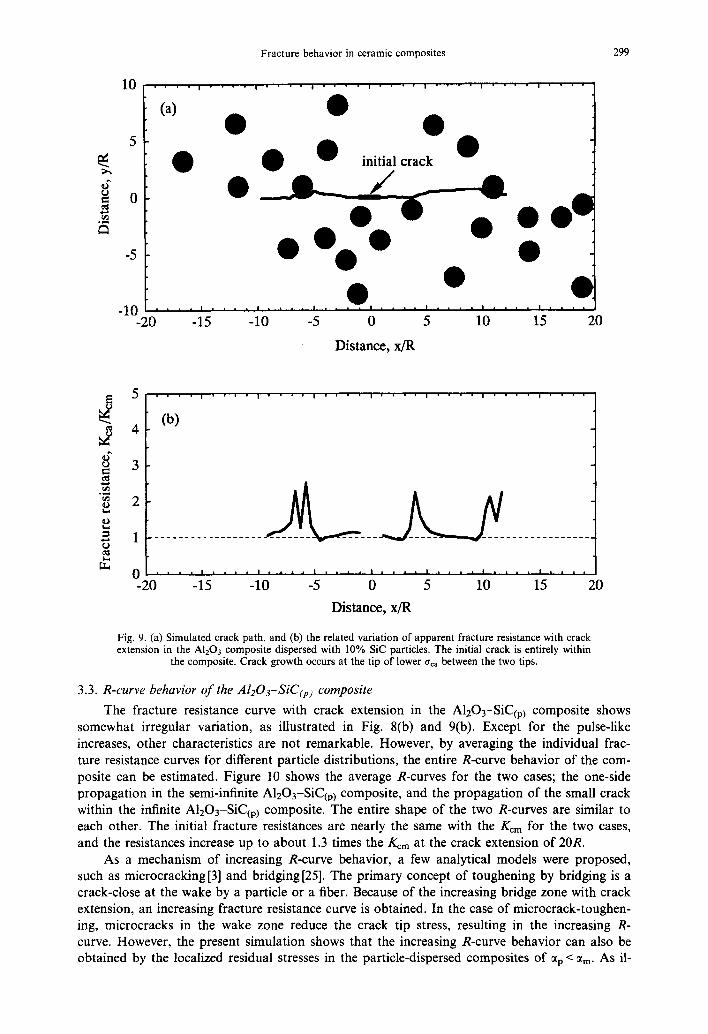
The simulated crack growth behavior shown in Figs 6 and 8 is a result from the propa- gation of the right tip only. The initial crack tip also starts to grow from the outside of the com- posite region, that is, a monolithic. If the initial crack exists completely within the composite, the two tips would compete to grow. Figure 9 shows the simulated path of the initially short crack within the A1203 matrix composite dispersed with 10% SiC particles. The length of the in- itial crack is 2R and the surface is flat. The particles were distributed according to the Poisson distribution not to overlap the crack plane. At every propagating steps, there are two crack tips able to grow and the resultant growth occurs at the tip of the lower aca between the two tips. The other simulation processes are identical to the above cases. The crack path and the variation of the gca a re very similar to the results of the one-side propagation of Fig. 8. A similar simu- lation with the identical idea was conducted for two-dimensional polycrystals by Kim et al. [5].
o
0 . . . .
(a)
5
0
-5
-1010 . . . .
. . . . i • @ • i . . . . I . . . .
0 @ @
@ @
l m . . . . l . . . . | . . . .
0 10 20 30
Distance, x/R
40
5
4
3
2
1
0 -10
, . ' , I , ' ' ' I ' ' ' ' I ' ' ' '
(b) • ° [ " ,
I
I
. . . . . .
| i i i I | i i i I i | | i ! . . . . I . . . .
0 10 20 30 40
Distance, x/R
Fig. 8. (a) Simulated crack path, and (b) the related variation of apparent fracture resistance with crack extension in the A1203 composite dispersed with 5% SiC particles. Crack propagates from left to right.
Fracture behavior in ceramic composites 299
o ~
0 . . . . , . . . . , . . . . , . . . . , . . . . , . . . . , . . . . , . . . .
5
-5
-10 -20
( a )
Q Q "~" initial crack - -
e eea • " . " •
. . . . . . . . . , . . . . . . . • . . . . . • I . . , • i . . . . . .
-15 -10 -5 0 5 10 15 20
Distance, x/R
o ~
t ~
E
5
4
3
2
1
• ' • , I ' ' ' • I • • • ' I . . • ' I , . • ' i . . . . I . . . . i . . . .
(b)
i i i | I . . . . i . + , ,
-20 -15 -10 I , , , . I . . , . I . , . , I , , , , I , , , ,
-5 0 5 10 15 20
Distance, x/R
Fig. 9. (a) Simulated crack path, and (b) the related variation of apparent fracture resistance with crack extension in the A1203 composite dispersed with 10% SiC particles. The initial crack is entirely within
the composite. Crack growth occurs at the tip of lower a¢, between the two tips.
3.3. R-curve behavior of the AI203-SiC(p) composite
The fracture resistance curve with crack extension in the A1203-SiC~p) composite shows somewhat irregular variation, as illustrated in Fig. 8(b) and 9(b). Except for the pulse-like increases, other characteristics are not remarkable. However, by averaging the individual frac- ture resistance curves for different particle distributions, the entire R-curve behavior of the com- posite can be estimated. Figure 10 shows the average R-curves for the two cases; the one-side propagation in the semi-infinite AlzO3-SiC(p) composite, and the propagation of the small crack within the infinite A1203-SiC~p) composite. The entire shape of the two R-curves are similar to each other. The initial fracture resistances are nearly the same with the gcm for the two cases, and the resistances increase up to about 1.3 times the Kern at the crack extension of 20R.
As a mechanism of increasing R-curve behavior, a few analytical models were proposed, such as microcracking [3] and bridging [25]. The primary concept of toughening by bridging is a crack-close at the wake by a particle or a fiber. Because of the increasing bridge zone with crack extension, an increasing fracture resistance curve is obtained. In the case of microcrack-toughen- ing, microcracks in the wake zone reduce the crack tip stress, resulting in the increasing R- curve. However, the present simulation shows that the increasing R-curve behavior can also be obtained by the localized residual stresses in the particle-dispersed composites of ~p < arm. As il-

300 B.-N. KIM et al.
. . . . . . . . . ! . . . . . . . . . ! . . . . . . . . .
. . . . . semi-infinite composite
infinite composite
~ 1.5
.o
1
0.5 . . . . . . . . . . . . . . . . . . . . . . . . . . . . .
0 10 20 30
Crack extenison, Ax/R
Fig. 10. Averaged fracture resistance curves with crack extension (R-curve) in both the semi-infinite and the infinite A1203 composite dispersed with 10% SiC particles. Each curve is an averaged one of 10
simulated curves for respective composites.
lustrated in Fig. 7, when the crack passes the particle, /(ca becomes larger than K~m. The loca- lized residual stress around the particle acts as a crack-closing mode behind the crack tip. With crack extension, the effective number of particles acting as a closing mode increases, resulting in increasing fracture resistance. The experimentally observed increasing R-curve in A1203-SiC(p) composite was also attributed to the residual stresses due to the thermal expansion mismatch between the matrix and the particle [26]. On the other hand, a decreasing R-curve will be obtained in the SiC-A1203(p) composite by a similar mechanism, when the consideration is con- fined in two dimensions.
3.4. Fracture toughness of the particle-dispersed composites
The introduction of the imaginary interface at r = 1.05R gives the same results as the repla- cement with a particle of radius 1.05R of ai=876 MPa (=966 MPa/1.052) and crack propa- gation along the actual interface. The residual stress distribution in the matrix results in no changes by the replacement, while the ai at the interface is reduced by 0.907 times, and the volume fraction of particles increases by 1.103 times. However, the reduced o- i may be obtained alternatively by reducing A T, without changing the material properties. In the above case, the A T has to be reduced to 0.907AT ( = - 1088°C), in order to obtain a ~i of 876 MPa. Accordingly, the testing temperature is not specified in the present simulation.
When the fracture resistance is strongly dependent on the microstructural path of the crack, the definition of the fracture toughness of the composite is not explicit. As in the case of the AlzO3-SiC(p) composite, the crack impinged on the particles shows a higher fracture resist- ance, while the unimpinged crack shows a lower resistance. As a simple method to evaluate the relative variation of the fracture toughness of the composite with respect to the volume fraction of particles, an averaging can be considered. By averaging/(ca in Fig. 6(b) and 8(b), respectively, the fracture toughness of the composite, /(cA, can be estimated roughly. Of course, the averaged value of /(cA is dependent on the considered region, especially in the AlzO3-SiC(p) composites which represent the pulse-like increases of the/(ca around the particles. In order to minimize the size effect, the considered region has to be set long enough compared with the particle radius. The following formula based on the energy concept is used to estimate/(cA:
/1 /.L \1 /2
zJ0 odx) (6, where L is the total propagated crack length, which is about 25-30R in the range of x > 0.

Fracture behavior in ceramic composites 301
Another problem in estimating the gcA is the entirely variant fracture resistance curve (R- curve) with crack extension. KcA will increase in the A12Oa-SiC(p) composite or decrease in the SiC-A1203.. composite with increasing L. Hence, the absolute value of gcA has no meaning.
k ) , , .
Only the relative variation with respect to the dispersed particles is worth noting. In Fig. 1 l, the variation of KcA is represented with respect to the adjusted volume fraction of particles for A T = - 1088°C. In the SiC-A12Oa~p~ composite, gcA decreases with the volume fraction of par- ticles and is about 0.5 times the Kcm at 30% A1203 particles, while gcA increases up to about 2 times in the AlzO3 composite of 30% SiC particles. Each value of gcA in Fig. 11 is an average of two simulated R-curves for different particle distributions. Because of the limited numbers of the simulation, the results show some scatter.
From the energetic viewpoint, crack deflection in a matrix induces an enhancement of frac- ture toughness which is proportional to the fracture surface area. However, if localized residual stresses are present, a crack would follow the path of lower fracture resistance so as to release the stresses. Hence, the radial fracture pattern appears in the A1203-SiC(p) composite, while the circumferential fracture pattern appears in the SiC-A1203.. composite. In the particle-dispersed
• t P ) .
composites, the crack deflection is a result of the existence of the localized residual stresses around the particles, and the fracture surface area is not directly concerned with the fracture toughness of the composites• Figure 12 shows the variation of the actual fracture surface area Ac normalized with the apparent fracture surface area A0. In the case of the SiC-A1203t ~ com- . . . . . p .
posite, although the degree of crack deviation (Ac/Ao) increases with the volume fraction of dis- persed particles, the fracture toughness decreases.
In the composites reinforced with spherical particles, several toughening mechanisms were proposed, such as crack pinning [9] and crack deflection [27]. In the composites where the loca- lized compressive stress exists in the circumferential direction of the particle, as in the SiC- A1203tp) composite, crack deflection is preferred to be applied rather than crack pinning, since the crack is repelled by the particles, resulting in crack deflection. Taya et al. [21] also analyzed the role of residual stresses in the toughening of the composites of % > ~m. However, the simu- lated fracture resistance in Fig. 6(b) decreases entirely with crack extension. This decreasing re- sistance may result from the two-dimensional characteristics of the present simulation. As pointed out in the simulation for two-dimensional polycrystals of lower grain boundary tough- ness than grain toughness [5], a crack propagates into the path of the lower fracture resistance, resulting in lower fracture toughness of the polycrystals (or the composites) than that of the
~d
o
<
2
i I l
• Al203-SiC(p) AT=-1088 °C
• SiC-Al203(p)
I I . . . . . . . . . . . . . . . . . . . . . . . . . . . . . . . . . . . . . . . . . . . . . . . . . . . . .
• m • • •
0 m I , I i I ,
0 10 20 30 40
Volume fraction of particles, %
Fig. 11. Predicted fracture toughness of the particle-dispersed composites with respect to volume frac- tion of particles.

302 B.-N. KIM et al.
¢ . )
<
o
>
o
o
1.2
1.15
1.1
1.05
!
• A1203-SiC(p)
• SiC-A1203(p)
• • •
0 10 20 30 40
Volume fraction of particles, %
Fig. 12. Actual fracture surface area (Ac) normalized with apparent fracture surface area (A0) of the particle-dispersed composites with respect to volume fraction of particles.
grain (or the matrix). In this sense, the crack propagation behavior in the composites of 0~p > a m is very similar to the case of the two-dimensional polycrystals: the toughness enhancement can- not be achieved from the two-dimensional simulation. The toughness enhancement in the com- posites of ap > am may be achieved by the three-dimensional connection of crack planes in the thickness direction. Twist deflection in the thickness direction was also suggested to be respon- sible for the toughening rather than tilt deflection in the propagating direction[19, 28].
In addition to the three-dimensional effect, there are other factors that are not able to be compared with the actual fracture toughness values, such as weak interfaces, particle shape, par- ticle fracture and microcracking at interfaces. The two-dimensional fracture toughnesses of the composites are quite different from the three-dimensional values. The present simulation of the crack path may only help to understand the fundamental crack propagation behavior in the par- ticle-dispersed composites.
On the other hand, the trapped crack in the composites of ap/am requires high/(ca for an escape from the particle. According to the analytical results on the toughening effect by both crack pinning and crack deflection occurring simultaneously in particle-dispersed composites [28], the toughening by crack pinning mechanism prevails the entire fracture toughness. Crack deflec- tion becomes a minor mechanism in the composites where crack pinning occurs. In addition, since the degree of deviation of the crack path in the A1203-SiC(p) composite due to crack trap- ping is larger than in the SiC-AI203~ composite, as illustrated in Fig. 12, the toughening in the
P . , .
composites of % < am may be accelerated by the three-dlmensmnal crack propagaUon. Thus, the present simulation also shows that the existence of the localized residual stresses may change the primary fracture mechanism of the particle-dispersed composites.
4. CONCLUSIONS
When the localized tensile stress exists in the radial direction around particles in particle- dispersed composites, a crack is repelled by the particles. In the SiC matrix composite dispersed with A1203 particles, the crack barely impinges on the particles. The related fracture resistance with crack extension decreases below the value of the matrix toughness due to the residual ten- sile stress in the radial direction. The estimated relative fracture toughness of the composite also decreases with the volume fraction of particles. The toughening in the actual composites of ap > a m is considered to occur by three-dimensional crack deflection.

Fracture behavior in ceramic composites 303
In the A1203 matrix composite dispersed with SiC particles, where the localized tensile stress exists in the circumferential direction around the particles, a crack is attracted and trapped by the particles. The related fracture resistance shows pulse-like increases up to about 5 times the value of the matrix toughness when the crack propagates along interfaces, and an increasing R-curve behavior with crack extension is predicted. The relative fracture toughness of the composite increases in proportion to the dispersed particles. The effective toughening in the composites of ~p < a m occurs by crack pinning.
Acknowledgements--The authors wish to thank Professor Nisitani of Kyushu University for the provision of the BFM program.
REFERENCES
I. Toda, H., Kobayashi, T. and Wada, Y., Fracture-mechanical simulation of a crack propagating in discontinuously- reinforced metal matrix composites. Journal of the Japanese Institute of Metals, 1995, 59, 94-102.
2. Evans, A. G. and Fu, Y., Some effects of microcracks on the mechanical properties of brittle solids-II, microcrack toughening. Acta Metallurgica, 1985, 33, 1525-1531.
3. Hutchinson, J. W, Crack tip shielding by micro-cracking in brittle solids. Acta Metallurgica, 1987, 35, 1605-1619. 4. Biner, S. B., A FEM analysis of crack growth in microcracking brittle solids. Engineering Fracture Mechanics, 1995,
51, 555-573. 5. Kim, B.-N., Wakayama, S. and Kawahara, M., Characterization of 2-dimensional crack propagation behavior by
simulation and analysis. International Journal of Fracture, 1996, 75, 247-259. 6. Gao, H. and Rice, J. R., A first-order perturbation analysis of crack trapping by arrays of obstacles. Journal of
Applied Mechanics, 1989, 56, 828-836. 7. Bower, A. F. and Ortiz, M., A three-dimensional analysis of crack trapping and bridging by tough particles. Journal
of the Mechanics and Physics of Solids, 1991, 39, 815--858. 8. Fares, N., Crack fronts trapped by arrays of obstacles: numerical solutions based on surface integral representation.
Journal of Applied Mechanics, 1989, 56, 837-843. 9. Evans, A. G., The strength of brittle materials containing second phase dispersions. Philosophical Magazine, 1972,
26, 1327-1344. 10. Swearengen, J. C., Beauchamp, E. K. and Eagan, R. J., Fracture toughness of reinforced glasses. In Fracture
Mechanics of Ceramics, Vol. 4. Plenum Press, New York, 1978, pp. 973-987. 11. Yuuki, R., Xu, J.-Q. and Schmauder, S., Simple method to analyze the residual thermal stress of dissimilar material
joints and some applications. Transactions of the Japanese Society of Mechanical Engineers, 1991, A57, 864-870. 12. Nisitani, H., Saimoto, A. and Noguchi, H., Versatile method of analysis of two-dimensional elastic problem by body
force method. Transactions of the Japanese Society of Mechanical Engineers, 1990, A56, 2123-2129. 13. Lawn, B. R. and Wilshaw, T. R., Fracture of Brittle Solids Cambridge University Press, Cambridge, 1975. 14. Cotterell, B. and Rice, J. R., Slightly curved or kinked cracks. International Journal of Fracture, 1980, 16, 155-169. 15. Erdogan, F. and Sih, G. C., On the crack extension in plates under plane loading and transverse shear. Journal of
Basic Engineering, 1963, 85, 519-527. 16. Sih, G. C., Strain energy factors applied to mixed mode crack problems. International Journal of Fracture Mechanics,
1974, 10, 305-321. 17. Hussain, M. A., Pu, S. L. and Underwood, J., Strain energy release rate for a crack under combined mode I and
mode II. Fracture Analysis ASTM STP, 1974, 560, 2-28. 18. Nuismer, R. J., An energy release rate criterion for mixed mode fracture. International Journal of Fracture, 1975, 11,
245-250. 19. Kim, B.-N. and Kishi, T., Estimation of fracture resistance of A1203 polycrystals from single-crystal values.
Materials Science and Engineering, 1994, A176, 371-378. 20. Davidge, R. W. and Green, T. J. The strength of two phase ceramic glass materials. Journal of Material Science,
1968, 3, 86-87. 21. Taya, M., Hayashi, H., Kobayashi, A. S. and Yoon, H. S., Toughening of a particulate-reinforced ceramic-matrix
composite by thermal residual stress. Journal of the American Ceramic Society, 1990, 73, 1382-1391. 22. Jang, B.-K., Enoki, M., Kishi, T., Lee, S.-H. and Oh, H.-K., Fracture behavior and toughening of alumina-based
composites fabricated by microstructural control. In Fracture Mechanics of Ceramics, Vol. 12. Plenum, New York, 1996, pp. 371-382.
23. Nandy, M.-O., Nose, T., Enoki, M. and Kishi, T., R-curve and cyclic fatigue behavior in alumina-particles-re- inforced silicon carbide. Material Transactions JIM, 1996, 37, 769-775.
24. Goldstein, R. V. and Salganik, R. L., Brittle fracture of solids with arbitrary cracks. International Journal of Fracture, 1974, 10, 507-523.
25. Mai, Y.-W. and Lawn, B, R., Crack-interface grain bridging as a fracture resistance mechanism in ceramics: II, theoretical fracture mechanics model.. Journal of the American Ceramic Society, 1987, 70, 289-294.
26, Kim, B.-N., Katsukawa, Y., Ahn, B.-W., Enoki, M. and Kishi, T., Evaluation of R-curve behavior in SiC particle- dispersed AI~O3 composites. Journal of the Ceramic Society of Japan, 1996, 104, 872-876.
27. Faber, K. T. and Evans, A. G., Crack deflection processes--I, Theory.. Acta Metallurgica, 1983, 31, 565-576. 28. Kim, B.-N. and Kishi, T., Toughening by crack pinning and crack deflection in particle-dispersed composites..
Journal of the Japanese Institute of Metals, 1994, 58, 728-733.
(Received 30 December 1996, in final form 25 August 1997, accepted 3 September 1997)