simulation driven nvh design
Post on 12-Sep-2014
1.356 views
DESCRIPTION
TRANSCRIPT

Innovation Intelligence®
Simulation Driven NVH Design
Harold Thomas, Ph.D.
Program Director
Altair Engineering, Inc.

Copyright © 2012 Altair Engineering, Inc. Proprietary and Confidential. All rights reserved. Copyright © 2012 Altair Engineering, Inc. Proprietary and Confidential. All rights reserved.
There is a Need to Reduce Design Verification Time
• Competition requires us to the shorten design cycle
• The time between the generation of the design and the manufacturing of
the tooling is reduced
• This puts pressure on the analysis team to verify the design in a short
time
• If flaws are found in the design, there must be a rapid determination of
the cause and possible suggestions for the cure.

Copyright © 2012 Altair Engineering, Inc. Proprietary and Confidential. All rights reserved. Copyright © 2012 Altair Engineering, Inc. Proprietary and Confidential. All rights reserved.
Reducing Time spent Debugging the FE Model
Common Statement: We don‘t have time to debug and fix the model!
• GROUNDCHECK not only shows that model is not good but also
specifies the elements that are causing the problem
• MECHCHECK is used to find mechanisms which are usually caused by
modeling errors
• .cmf file is created showing
elements that have low quality
• .interface file shows fluid-
structure coupling

Copyright © 2012 Altair Engineering, Inc. Proprietary and Confidential. All rights reserved. Copyright © 2012 Altair Engineering, Inc. Proprietary and Confidential. All rights reserved.
Reducing Time spent Debugging the FE Model
Common Statement: We don‘t have time to debug and fix the model!
• No PARAM,BAILOUT to mask modeling errors
• Erroneous RBE3 elements are detected
• Spiders connected to solids with rotational DOF
• Free spiders not connected to any structure
• Understandable Error messages point to specific problems with the
model *** ERROR # 772 ***
It is invalid to use a free grid as an independent grid in RBE3 data.
Free spiders are not allowed to be independent grids in RBE3 data.
RBE3 id = 10
grid id = 11
free components = 123
• Time spent debugging models with wrong results is reduced from days
to minutes

Copyright © 2012 Altair Engineering, Inc. Proprietary and Confidential. All rights reserved.
AMSES Eigensolver
• NVH problems require an eigensolver that can calculate thousands for
modes for problems with millions of DOF
• Lanczos is not a solution
• The eigensolver must have special features for NVH
• Load vector reduction to modal space
• Fluid-Structure Coupling (Area) matrix reduction to modal space
• Structural Damping (GE) matrix reduction to modal space
• Residual Vector (RESVEC) generation
• Must be able to handle free-free structures with automatic PARAM,INREL,-2
• Solutions for frequency response, transient response, and CMS Super
Element creation
• Must SMP parallel for efficiency

Copyright © 2012 Altair Engineering, Inc. Proprietary and Confidential. All rights reserved.
OptiStruct EigenSolver for NVH
• OptiStruct now has an efficient EigenSolver for NVH problems
• New EIGRA data is used
• Similar to EIGRL data (see next slide)
• Has accuracy control (AMPFFACT)
• Increased accuracy will increase run times
• Automatically increased for powertrain (solid) models
• The number of CPU’s used is the same as the number used by OptiStruct
• Controlled by –ncpu or –nproc command line arguments
• Works on both Windows and LINUX computers
• No issues with unconnected structures
• Typical of CMS Super Elements created with the CBN method
• No additional draw of HyperWorks Units (Still just 25)
• No additional license or installation

Copyright © 2012 Altair Engineering, Inc. Proprietary and Confidential. All rights reserved.
OptiStruct EigenSolver for NVH input data
EIGRA
Bulk Data Entry
EIGRA – Real Eigenvalue Extraction Data using Automated Multi-Level Sub-structuring
Description:
Defines the data need to perform eigenvalue analysis with the Automated Multi-Level Sub-structuring technique
Format:
(1) (2) (3) (4) (5) (6) (7) (8) (9) (10)
EIGRA SID V1 V2 ND AMPFFACT NORM

Copyright © 2012 Altair Engineering, Inc. Proprietary and Confidential. All rights reserved.
Performance against Lanczos on PC
AMSES VS Lanczos for Modal FRF solution
0 10000 20000 30000 40000 50000 60000 70000 80000
AMSES
Lanczos
elapsed time (s)
Eigen Solution
Structral Damping
Other
EIGRA reduces both Area and Damping matrices
EIGRA supports the internal residual vector calculation
technique to enhance solution accuracy
• 2.2 Million Degree of freedom, 1369 modes, w/ structural damping, 200 excitation frequencies, 1CPU
• Dell T7500, Xeon X5550 2.67GHz, 12GB RAM, regular disk, 64bit Windows Xp
Copyright © 2012 Altair Engineering, Inc. Proprietary and Confidential. All rights reserved.
EIGRA features
• Standard feature of OptiStruct (same as EIGRL)
• Runs on both Windows and LINUX computers
• Runs quickly on local workstations
• Uses just 25 HyperWorks Units
• Can be used for NVH problems
Copyright © 2012 Altair Engineering, Inc. Proprietary and Confidential. All rights reserved. Copyright © 2012 Altair Engineering, Inc. Proprietary and Confidential. All rights reserved.
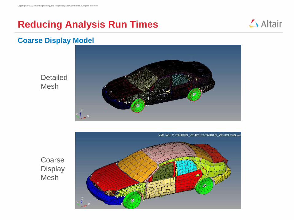
Reducing Analysis Run Times
Coarse Display Model
Detailed
Mesh
Coarse
Display
Mesh

Copyright © 2012 Altair Engineering, Inc. Proprietary and Confidential. All rights reserved. Copyright © 2012 Altair Engineering, Inc. Proprietary and Confidential. All rights reserved.
Reducing Analysis Run Times
Coarse Display Model
Results on
Detailed
Mesh
Results on
Coarse
Display
Mesh

Copyright © 2012 Altair Engineering, Inc. Proprietary and Confidential. All rights reserved.
1. Help to understand which attachment points dominate the response
2. Help to understand if the high response contribution is due to
- High transfer function
- High force
- High local point mobility
3. If transfer function is high relative to each other or to generic targets
- Reduce transfer function
4. If force is high
- Re-tune mount rates to rebalance forces
5. If local point mobility is high
- Increase local stiffness
Why Perform Transfer Path Analysis

Copyright © 2012 Altair Engineering, Inc. Proprietary and Confidential. All rights reserved.
• Transfer path analysis (TPA) is a complicated, and error prone process that involves two separate runs and post processing tool:
• First run - Calculate unit input Transfer Functions (response from each load)
and the Point Mobility (Velocity of the loaded point). • Requires hundreds of subcases (requires automation)
• Results in a huge punch file. The input file has to be created from using automation because there are so many subcases.
• Second run – Calculate Operating (Reaction) Forces using the full vehicle model at all loading frequencies. • Results in a huge punch file
• Extra computation of path contribution in the post processing tool.
• Path Participation = Transfer Function X Reaction Force
• Lots of book keeping needed for the post-processing tool
• It is computationally expensive to create the above punch files
The Two Step Process
Copyright © 2012 Altair Engineering, Inc. Proprietary and Confidential. All rights reserved.
• Implemented a new mathematical formulation by taking advantage of certain system matrix characteristics. The computational time is also reduced dramatically.
• Transfer path participation is directly calculated in the full vehicle run under the operating load. Computational time for post processing tool is saved.
• Very easy to setup the input data.
• Transfer function, point mobility, reaction force at each connection DOF, and partial contribution to each response by every connection DOF will be in one compressed file (.h3d file)
• PEAKOUT card can be used to calculate only at the filtered peak frequencies.
• Computational time is reduced from days to hours.
The One Step Process

Copyright © 2012 Altair Engineering, Inc. Proprietary and Confidential. All rights reserved.
F
r
Ff
F
r F
f
F
t F
e
Results can be viewed in NV Director

Copyright © 2012 Altair Engineering, Inc. Proprietary and Confidential. All rights reserved. Copyright © 2012 Altair Engineering, Inc. Proprietary and Confidential. All rights reserved.
Detailed Output at Peak Response Frequencies
Operating Deformed Shape and Participation Output
• It takes too long and uses too much disk space to get the operating deformed
shape and participation output at each frequency
• The engineer has manually determine the problem frequencies, specify these
frequencies in the input data, and submit a second run
• OptiStruct PEAKOUT data automatically determines the critical frequencies and
generates the operating deformed shape and modal, grid, and panel participation
output in a single run
Peak Frequencies

Copyright © 2012 Altair Engineering, Inc. Proprietary and Confidential. All rights reserved. Copyright © 2012 Altair Engineering, Inc. Proprietary and Confidential. All rights reserved.
Fast Modal Solution with Damping
• OptiStruct FASTFR solver
• Fast Frequency Response Solution based on Thousands of
Modes with Viscous and/or Structural Damping
• Modal Damping can also be present with sparse structural
damping and/or viscous damping
• Works with Frequency Dependent Structural Materials
(PBUSHT) and frequency dependent fluid properties (PAABSF)
• Can be used with coupled fluid-structure (NVH) analysis with fluid
material (MAT10 GE) damping
• Available for enforced motion (SPCD)
• Multi-threaded with nearly linear speedup
• No Additional Cost
• Runs on Windows and Linux
Copyright © 2012 Altair Engineering, Inc. Proprietary and Confidential. All rights reserved.
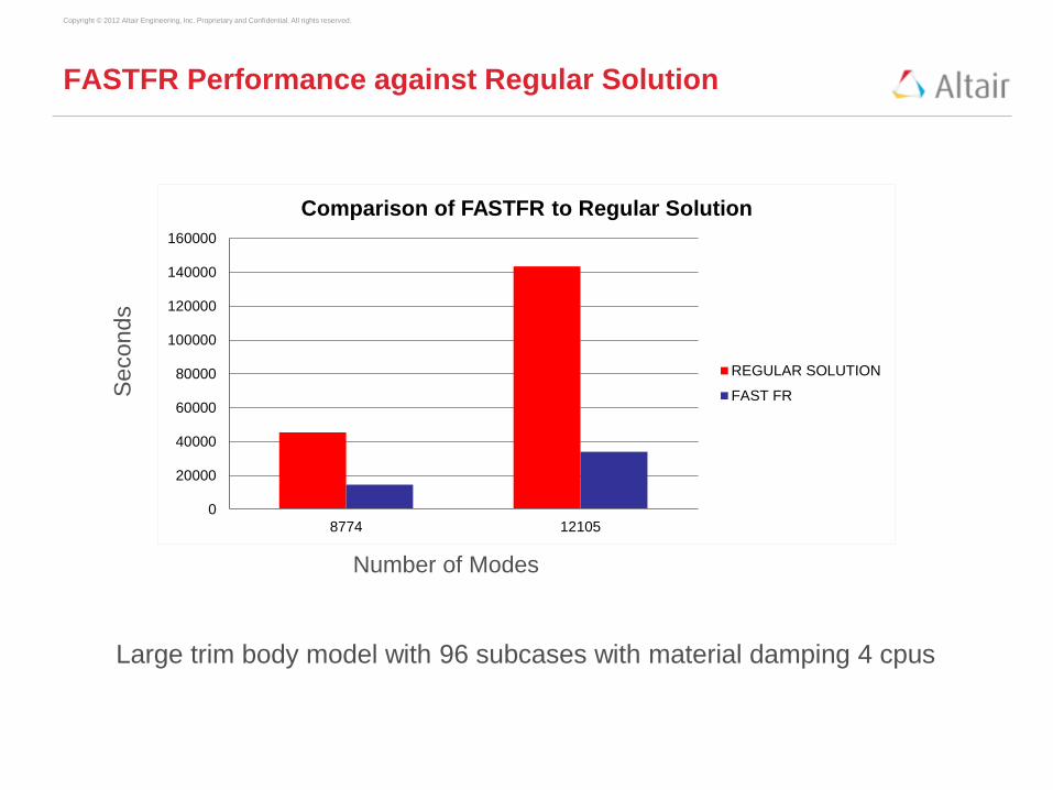
FASTFR Performance against Regular Solution
Number of Modes
Seconds
Large trim body model with 96 subcases with material damping 4 cpus
0
20000
40000
60000
80000
100000
120000
140000
160000
8774 12105
Comparison of FASTFR to Regular Solution
REGULAR SOLUTION
FAST FR

Copyright © 2012 Altair Engineering, Inc. Proprietary and Confidential. All rights reserved. Copyright © 2012 Altair Engineering, Inc. Proprietary and Confidential. All rights reserved.
Reducing Analysis Run Times
CMS Super Elements
• Fast CMS Super Element creation using AMSES
• Includes viscous and structural Damping
• Combined Fluid-Structure Super Element is available
• Residual Run Results are Line on Line with full mesh analysis
• Only a single H3D file is required for each Super Element
• Analysis time reduced from hours to minutes
• Can be run on a laptop
• Allows for quick re-analysis
• Allows for optimization

Copyright © 2012 Altair Engineering, Inc. Proprietary and Confidential. All rights reserved. Copyright © 2013 Altair Engineering, Inc. Proprietary and Confidential. All rights reserved.
Optimization Disciplines
Topography Topology Free Size
Free Shape Size Shape

Copyright © 2012 Altair Engineering, Inc. Proprietary and Confidential. All rights reserved. Copyright © 2012 Altair Engineering, Inc. Proprietary and Confidential. All rights reserved.
OptiStruct for Reducing Design Verification Time
• Debugging and fixing the finite element model
• GROUNDCHECK and MECHCHECK
• Modeling errors detected and reported with understandable messages
• Elimination of numerical issues
• Reducing analysis run time
• PEAKOUT results selection
• 1 Step Transfer Path Analysis
• AMSES with coarse model 2D PLOTEL elements
• Parallel modal system of equations solutions (FASTFR)
• Single file based CMS Super Element Analysis
• Optimization with CMS Super Elements
Fr
Ff
Fr
Ff Ft
Fe