simpull cable-in-conduit
TRANSCRIPT

SIMpull® Cable-In-ConduitInstallation Guide


Product DescriptionScope of GuideSafetyProper Shipping & Handling Transporting Reels Reel PayoffPreparation for Installation Disconnect Cable at Ends Position Reel Trailer Pulling Heads or EyesInstallation Trenching Plowing Directional Boring Inner Duct Bending & Backfill Cutting Conduit at Termination Points Cutting Conduit at Reel EndAppendix AAppendix B
1112
4
6
1112
Table of Contents
SIMpull ® Cable-In-Conduit Installation Guide southwire.com
1
Product Description
Southwire Company’s SIMpull ® Cable-In-Conduit system consists of either low voltage or medium voltage cables that are preassembled in a continuous length coilable polyethylene pipe. The number and size of cables installed in the conduit is determined by both the field application and by the end user. The size of the conduit can be adjusted to accommodate the necessary cables.
Scope
This Installation Guide is provided to assist the user in the proper installation techniques for the direct burial directional boring, or pulling as inner duct of the SIMpull Cable-In-Conduit assembly. Methods described in this guide are only recommendations and are offered as suggestions for proper handling and installation practices for SIMpull Cable-In-Conduit.
Safety
The methods and procedures in this guide are recommendations only and are not intended to replace or modify the user’s standard operating procedures or safety requirements. Recommendations in this guide are only intended as suggestions for the proper handling and installation of the SIMpull Cable-In-Conduit assembly.
As with any work project, prior to the beginning of work, all personnel should be thoroughly familiar with the products and procedures necessary to complete the day’s operations. Proper PPE, work area protection, and the safe use of equipment and material are the first priority.
All local, state, and Federal codes and safety requirements must be followed along with proper work site protection and traffic control in areas where indicated. As with the installation of any below ground equipment, all precautions concerning buried installations shall also be incorporated.
SIMpull ® Cable-In-Conduit Installation Guide southwire.com
2
Proper Shipping and Handling
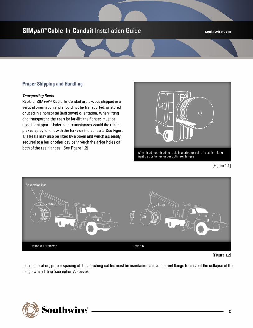
Transporting ReelsReels of SIMpull ® Cable-In-Conduit are always shipped in a vertical orientation and should not be transported, or stored or used in a horizontal (laid down) orientation. When lifting and transporting the reels by forklift, the flanges must be used for support. Under no circumstances would the reel be picked up by forklift with the forks on the conduit. [See Figure 1.1] Reels may also be lifted by a boom and winch assembly secured to a bar or other device through the arbor holes on both of the reel flanges. [See Figure 1.2]
When loading/unloading reels in a drive-on roll-off position, forks must be positioned under both reel flanges
[Figure 1.1]
[Figure 1.2]
Option A I Preferred Option B
Separation Bar
StrapStrap
In this operation, proper spacing of the attaching cables must be maintained above the reel flange to prevent the collapse of the flange when lifting (see option A above).
SIMpull ® Cable-In-Conduit Installation Guide southwire.com
3
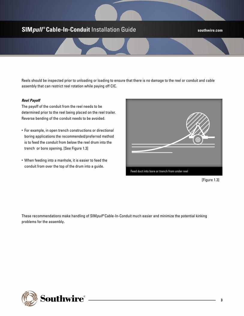
Reel PayoffThe payoff of the conduit from the reel needs to be determined prior to the reel being placed on the reel trailer. Reverse bending of the conduit needs to be avoided.
• For example, in open trench constructions or directional boring applications the recommended/preferred method is to feed the conduit from below the reel drum into the trench or bore opening. [See Figure 1.3]
• When feeding into a manhole, it is easier to feed the conduit from over the top of the drum into a guide.
These recommendations make handling of SIMpull®Cable-In-Conduit much easier and minimize the potential kinking problems for the assembly.
Reels should be inspected prior to unloading or loading to ensure that there is no damage to the reel or conduit and cable assembly that can restrict reel rotation while paying off CIC.
[Figure 1.3]
Feed duct into bore or trench from under reel

SIMpull ® Cable-In-Conduit Installation Guide southwire.com
4
Preparation for Installation
Disconnect Cable at EndsThere is a placard on one of the reel flanges that warns the installer that there is a difference in the duct and cable length. This length difference develops as you unroll the conduit off the reel. This results in the conduit becoming longer than the cable inside. The allowance for the cable-to-duct difference need be no more than 1.5% of the conduit length unrolled. As stated on the placard, the cable movement occurs at the duct end being unrolled.
Because of this length difference between the conduit and the cable inside, it is VERY important to first cut the duct free of the reel flange, remove the end cap, and cut the restraint attaching the cable to the conduit on the top/pulling end of the reel only. Once the cable has been freed from the conduit, prepare the end for pulling, remembering to seal the end of the cable from moisture ingress. With the pulling apparatus and seal installed, SIMpull ® Cable-In-Conduit is ready for installation.
Position Reel TrailerReel trailers should be positioned such that you can feed the conduit as directly as possible toward the centerline of the placement sight. [See Figure 1.4]Sidewalk
Yes
No
Open Trench
Potential for Damage
[Figure 1.4]
SIMpull ® Cable-In-Conduit Installation Guide southwire.com
5
Pulling Grip or EyesAttachment to SIMpull ® Cable-In-Conduit, using one of the following methods allows full utilization of the working strength of that duct size.
• The pulling force that can be safely applied during installation of SIMpull Cable-In-Conduit is a function of the conduit diameter and the wall thickness.
• A listing of working strengths for all conduit sizes is in Appendix A.
The primary method for attaching to SIMpull Cable-In-Conduit is by the use of a Wire Mesh Basket type-pulling grip.
• Due to the hardness and slickness of the surface, apply several compressible bands of friction tape to the SIMpull Cable-In-Conduit before installing the grip.
• The first band of tape should be applied approximately 6” from the end of the conduit and additional bands should be applied every 6” until there are bands of tape over the length of conduit that will be covered by the pulling grip.
• The conduit must have an end cap installed prior to the pulling grip being installed.
• Slip the pulling grip over the end of the capped conduit and tape bands and pull the grip down tightly.
• Apply tape from the surface of the duct up onto the end of the pulling head about 2”.
• Do not extend the tape on to the pulling head any more than the 2.” Additional tape will restrict the pulling grip’s compressive potential and greatly limit the allowable pulling tensions for that installation.
• Installation of an adjustable hose clamp over the end of the pulling grip to hold the pulling grip in place is also an acceptable option.
Alternatives to the use of the basket pulling grip would be a screw in eye or crimp on eye.
• If using either of these alternatives, DO NOT attach the cable end to the inside of the unit. Allow the cable to move freely.
No matter what attachment is used for pulling in SIMpull Cable-In-Conduit, it is imperative that a ball bearing swivel be used between the pulling line and the conduit pulling attachment. This prevents the transfer of twisting forces onto the duct from the pulling line. Do not consider a grip with a ‘built-in’ swivel as a replacement for the ball bearing swivel.
SIMpull ® Cable-In-Conduit Installation Guide southwire.com
6
Installation
TrenchingThe purpose of this section is to cover specific details on using Southwire SIMpull® Cable-In-Conduit in trenching applications and does not offer specific instructions on trenching. Note, during construction of the trench, the installer should consider that every deviation in elevation or direction will have a negative impact on cable replacement tension. Enforcement of a policy of proper trench preparation assures the least resistance to cable pulling. In any case, the number of 90° bends should be limited to a maximum of 4. In general SIMpull Cable-In-Conduit should be installed in the trench as straight as possible (no “snaking”) and with as few bends as possible.
Minimize the severity of a bend when a change in depth is necessary. Provide a gradual transition from bore pits to desired trench depth and when forced to deviate around obstacles. When rapid grade changes exist, use shading or backfill to make the change as gradual as possible.
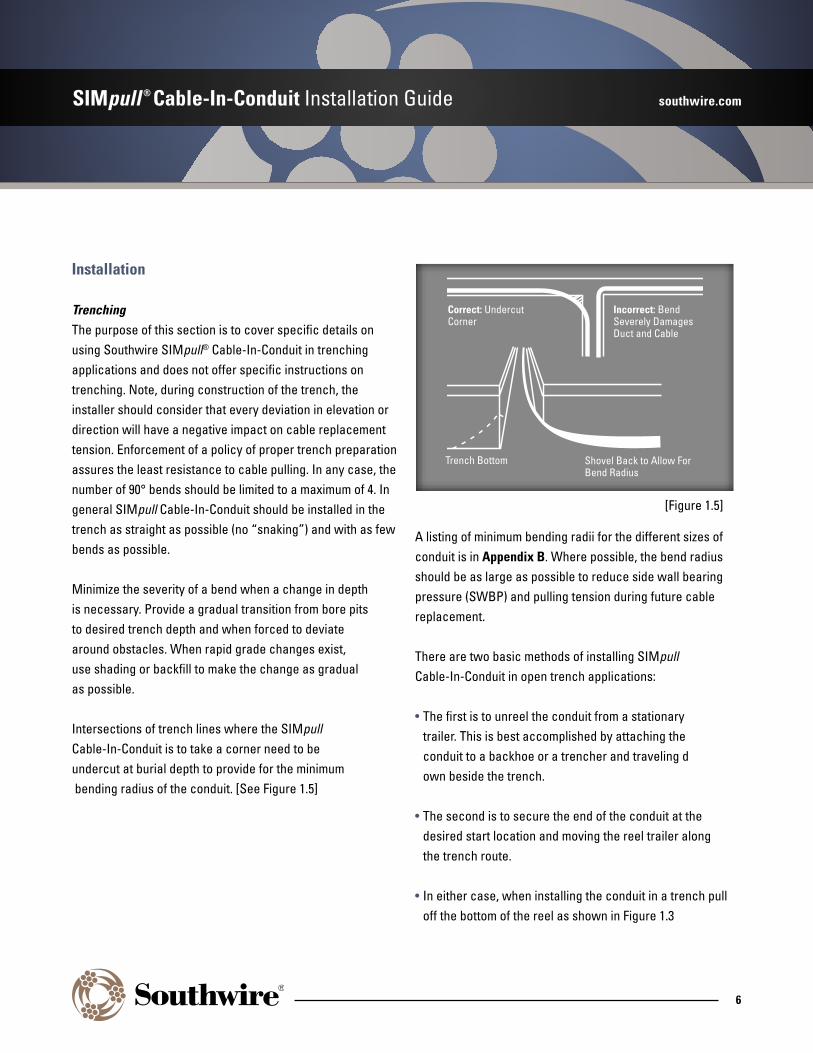
Intersections of trench lines where the SIMpull Cable-In-Conduit is to take a corner need to be undercut at burial depth to provide for the minimum bending radius of the conduit. [See Figure 1.5]
A listing of minimum bending radii for the different sizes of conduit is in Appendix B. Where possible, the bend radius should be as large as possible to reduce side wall bearing pressure (SWBP) and pulling tension during future cable replacement.
There are two basic methods of installing SIMpull Cable-In-Conduit in open trench applications:
• The first is to unreel the conduit from a stationary trailer. This is best accomplished by attaching the conduit to a backhoe or a trencher and traveling d own beside the trench.
• The second is to secure the end of the conduit at the desired start location and moving the reel trailer along the trench route.
• In either case, when installing the conduit in a trench pull off the bottom of the reel as shown in Figure 1.3
Correct: Undercut Corner
Incorrect: Bend Severely Damages Duct and Cable
Trench Bottom Shovel Back to Allow For Bend Radius
[Figure 1.5]

SIMpull ® Cable-In-Conduit Installation Guide southwire.com
7
During the payout of the duct from the reel, avoid over spinning of the reel. This can be achieved by using a trailer equipped with a hand brake, a braking system or by assigning a worker as a reel tender. Pulling the conduit off the reel under slight tension allows for the straightest installation. In all of these installation procedures, there should be an allowance at the front end of the conduit for the anticipated difference in the length of cable inside the conduit. As mentioned previously the added length of conduit over that of the cable is approximately 1.5%. For a 200’ pull, this results in the need to bring the end an additional 3’ to ensure there is adequate cable for necessary termination and connections.
When the conduit is cut at the end of a run, it is imperative that the cut end be sealed with an end cap immediately. You have selected SIMpull® Cable-In-Conduit to provide a safe environment for your cable, so protect the integrity of your duct system by keeping it capped during and after installation.
When working in areas with a high water table, the trench may fill with water before restoration is complete. Since SIMpull Cable-In-Conduit is buoyant, the following steps should be followed:
• Water should be pumped out of the trench prior to the installation of the conduit.
• Plan on restraining the conduit in the bottom of the trench by using sand bags or other restraining material.
• Returning the soils to the trench will not restrain the conduit in a flooded trench.
• It should be noted that this same situation can exist when using concrete slurry as the backfill. Conduit must be secured down to prevent floating.
Directional BoringAs with other installation methods always remove the restraint on the conductor at the start end and let the conductor(s) go unattached. Ensure that a sealed end cap has been installed on the front end of the conduit to keep any foreign matter from entering and clogging the conduit.
Pull additional slack through the bore to ensure there is the adequate cable to account for the 1.5% excess conduit.
As with the trench installation discussed previously, use a swivel between the conduit grip or eye and the back reamer.
Use a back reamer that is at least 1.5 times the outside diameter of the conduit assembly being installed. As an example, a 1.5”conduit has an OD of 1.9”. 1.5 X 1.9”= 2.85” so a 3” back reamer should be used. If two 1.5” conduits are to be installed then the equivalent OD would be 3.8” and 3.8”x1.5 = 5.7 so 6” back reamer should be used. Using a back reamer smaller than 1.5X can cause a build-up of water pressure in the bore hole that may necessitate digging a hole along the drill route to relieve the water pressure.

SIMpull ® Cable-In-Conduit Installation Guide southwire.com
8
PlowingThere are two basic methods of plowing: pull plowing and chute plowing. SIMpull® Cable-In-Conduit is suitable for both techniques, although both require different product considerations. SIMpull Cable-In-Conduit provides the mechanical protection and strength necessary to use these construction methods with delicate cables.
As with the trenching technique, the conduit route is very important. Every deviation in elevation or direction will have a negative impact on cable pulling tensions in the future. Minimizing any elevation or directional changes will assure the least resistance to future cable pulling.
In most cases, it is beneficial to “pre-rip” the route prior to installing SIMpull Cable-In-Conduit. While this is sometimes viewed as an unproductive step, it can increase ultimate plow speed and also locate potential problems such as existing services, utilities, and immovable objects prior to duct placement.
Pull PlowingThis process involves pulling the duct into the ground behind either a vibratory or static plow blade. This method is efficient for placing short lengths of SIMpull Cable-In-Conduit and routes where there are frequent bores and laterals.
Significant tension can be developed while pull plowing. It is difficult to accurately predict how much tension will develop when pull plowing in an unfamiliar area. Pull plowing should be limited to a maximum length of 200’
SIMpull Cable-In-Conduit should always be attached to the plow with a swivel behind the tunneling “bullet” that is used to form the opening for the CIC assembly. The plow needs to be set to open a hole with the bullet to a diameter of at least 1” larger than the outside diameter of the conduit.
Chute PlowingThis process involves feeding SIMpull Cable-In-Conduit through a chute attached to the back of the plow blade. Minimal tension is applied to the assembly, allowing long lengths to be plowed without overstressing the conduit assembly.
The chute interior must be free of surface roughness, burrs, or sharp edges that can damage the conduit. There should be a removable gate on the chute to facilitate conduit placement in the plow chute. The inside diameter of the chute should be approximately 1/2” larger than the outside diameter of the conduit being installed. The radius of the bend at the bottom of the plow should be at least 20x the outside diameter of the conduit (see Appendix B for a listing of conduit diameters).
SIMpull ® Cable-In-Conduit Installation Guide southwire.com
9
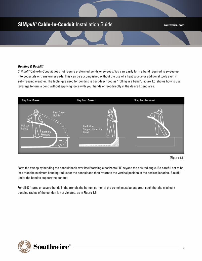
Bending & BackfillSIMpull® Cable-In-Conduit does not require preformed bends or sweeps. You can easily form a bend required to sweep up into pedestals or transformer pads. This can be accomplished without the use of a heat source or additional tools even in sub-freezing weather. The technique used for bending is best described as “rolling in a bend”. Figure 1.6 shows how to use leverage to form a bend without applying force with your hands or feet directly in the desired bend area.
Form the sweep by bending the conduit back over itself forming a horizontal ‘U’ beyond the desired angle. Be careful not to be less than the minimum bending radius for the conduit and then return to the vertical position in the desired location. Backfill under the bend to support the conduit.
For all 90° turns or severe bends in the trench, the bottom corner of the trench must be undercut such that the minimum bending radius of the conduit is not violated, as in Figure 1.5.
Step One: Correct Step Two: Correct Step Two: Incorrect
Pull UpLightly
Push DownLightly
Roll Bend Forward
Backfill to Support Under the Bend
[Figure 1.6]
SIMpull ® Cable-In-Conduit Installation Guide southwire.com
10
Cutting Conduit at Termination PointsIt is important to ensure that there is adequate extra length of conduit pulled into the termination point/cabinet to ensure there is adequate cable to make the necessary connections. Southwire recommends the use of a ring style cutter for removing the excess conduit to allow for cable termination. (The use of ratchet cutters or saws can potentially cause damage to the cable inside the conduit.)
Make several revolutions around the entire circumference of the conduit with the ring cutter increasing the pressure after each complete revolution till the conduit has been “snapped off”. De-burr any sharp edges so that no damage will be done to the cable insulation.
To ensure the continued integrity of the conduit, It is recommended that either a cable boot be installed to seal the end of the conduit or a material compatible with the cable and conduit be used to seal the end of the conduit around the cable to keep dirt, mud or other foreign objects from entering the conduit and compromising the assembly.
Cutting Conduit at Reel EndEnsure that ends on both sides of the prospective cut point are secured to prevent recoil from causing damage or injury.Cable and conduit at this point can be cut using a reciprocating saw, hack saw, circular saw or ratchet style pipe cutter. Once conduit and cable have been cut it is important to seal the ends of the conductors and to install and end cap on the conduit to ensure no foreign material enters the conduit.
Installation Questions?Please contact your Southwire representative or call our Product Support line at 1-800-444-1700, extension 4427.
SIMpull ® Cable-In-Conduit Installation Guide southwire.com
11
Appendix A
Safe Working Strengths for SIMpull® Cable-In-Conduit
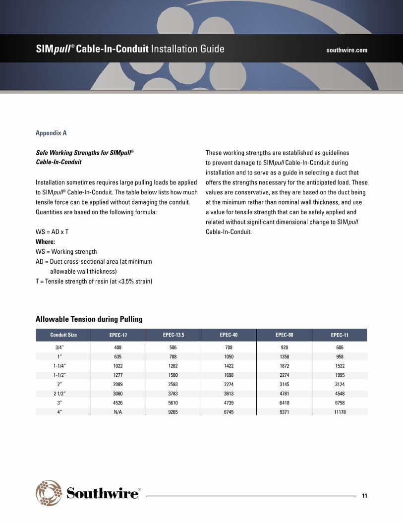
Installation sometimes requires large pulling loads be applied to SIMpull® Cable-In-Conduit. The table below lists how much tensile force can be applied without damaging the conduit. Quantities are based on the following formula:
WS = AD x TWhere:WS = Working strengthAD = Duct cross-sectional area (at minimum allowable wall thickness)T = Tensile strength of resin (at <3.5% strain)
These working strengths are established as guidelines to prevent damage to SIMpull Cable-In-Conduit during installation and to serve as a guide in selecting a duct that offers the strengths necessary for the anticipated load. These values are conservative, as they are based on the duct being at the minimum rather than nominal wall thickness, and use a value for tensile strength that can be safely applied and related without significant dimensional change to SIMpull Cable-In-Conduit.
3/4”
1”
1-1/4”
1-1/2”
2”
2 1/2”
3”
4”
Conduit Size
408
635
1022
1277
2089
3060
4526
N/A
EPEC-17
506
788
1262
1580
2593
3783
5610
9265
EPEC-13.5
708
1050
1422
1698
2274
3613
4739
6745
EPEC-40
920
1358
1872
2274
3145
4781
6418
9371
EPEC-80
Allowable Tension during Pulling
606
958
1522
1995
3124
4548
6758
11178
EPEC-11
SIMpull ® Cable-In-Conduit Installation Guide southwire.com
12
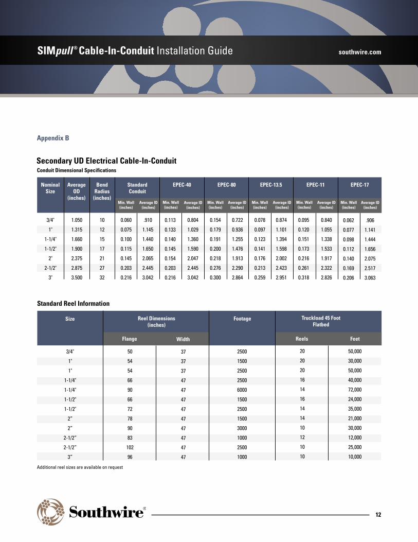
Appendix B
Secondary UD Electrical Cable-In-Conduit
Nominal Size
AverageOD
(inches)
BendRadius
(inches)
Standard Conduit
EPEC-40 EPEC-80 EPEC-13.5 EPEC-11
Min. Wall(inches)
Min. Wall(inches)
Min. Wall(inches)
Average ID(inches)
Min. Wall(inches)
Min. Wall(inches)
Average ID(inches)
Average ID(inches)
Average ID(inches)
Average ID(inches)
3/4"
1"
1-1/4"
1-1/2"
2"
2-1/2"
3"
1.050
1.315
1.660
1.900
2.375
2.875
3.500
10
12
15
17
21
27
32
0.060
0.075
0.100
0.115
0.145
0.203
0.216
.910
1.145
1.440
1.650
2.065
2.445
3.042
0.113
0.133
0.140
0.145
0.154
0.203
0.216
0.804
1.029
1.360
1.590
2.047
2.445
3.042
0.154
0.179
0.191
0.200
0.218
0.276
0.300
0.722
0.936
1.255
1.476
1.913
2.290
2.864
0.078
0.097
0.123
0.141
0.176
0.213
0.259
0.874
1.101
1.394
1.598
2.002
2.423
2.951
0.095
0.120
0.151
0.173
0.216
0.261
0.318
0.840
1.055
1.338
1.533
1.917
2.322
2.826
Conduit Dimensional Specifications
3/4"
1"
1"
1-1/4"
1-1/4"
1-1/2"
1-1/2"
2”
2”
2-1/2”
2-1/2”
3”
50
54
54
66
90
66
72
78
90
83
102
96
37
37
37
47
47
47
47
47
47
47
47
47
2500
1500
2500
2500
6000
1500
2500
1500
3000
1000
2500
1000
20
20
20
16
14
16
14
14
10
12
10
10
50,000
30,000
50,000
40,000
72,000
24,000
35,000
21,000
30,000
12,000
25,000
10,000
Size Reel Dimensions(inches)
Width
Footage Truckload 45 FootFlatbed
Reels Feet
Standard Reel Information
Additional reel sizes are available on request
Flange
EPEC-17
Min. Wall(inches)
Average ID(inches)
0.062
0.077
0.098
0.112
0.140
0.169
0.206
.906
1.141
1.444
1.656
2.075
2.517
3.063

Southwire Company, LLC. • One Southwire Drive • Carrollton, GA 30119 • www.southwire.com • 800.444.1700©2018 Southwire Company, LLC. All Rights Reserved. ®Registered Trademark and ™Trademark of Southwire Company, LLC.