simple and powerful visual stimulus generator
TRANSCRIPT

Computer Methods and Programs in Biomedicine 58 (1999) 175–180
Simple and powerful visual stimulus generator
Jan Kremlac' ek *, Miroslav Kuba, Zuzana Kubova, Frantis' ek Vıt
Faculty of Medicine, Department of Pathophysiology, Charles Uni6ersity, S& imko6a 870, 500 01 Hradec Kralo6e, Czech Republic
Received 6 October 1997; received in revised form 1 April 1998; accepted 26 May 1998
Abstract
We describe a cheap, simple, portable and efficient approach to visual stimulation for neurophysiology which doesnot need any special hardware equipment. The method based on an animation technique uses the FLI autodeskanimator format. This form of the animation is replayed by a special program (‘player’) providing synchronisationpulses toward recording system via parallel port. The ‘player’ is running on an IBM compatible personal computerunder MS-DOS operation system and stimulus is displayed on a VGA computer monitor. Various stimuli createdwith this technique for visual evoked potentials (VEPs) are presented. © 1999 Elsevier Science Ireland Ltd. All rightsreserved.
Keywords: Visual stimulus generator; VEPs; Visual stimuli; Motion-onset; Pattern-reversal
1. Introduction
Many special electronic and even mechanicdevices have been constructed for visual stimula-tion in neuroscience. They are generally developedeither for electrophysiological experiments (VSGCambridge Research Systems, UK, VENUS:S) orthey are intended for clinical use. The first devicesare very flexible, however, due to their complex-ity, it can be difficult to control them. In contrast,those utilised as a part of clinical instrumentationcan be easily used, however, they are too rigid for
the introduction of a new stimulation method. Inaddition, both of them are usually very expensive.
For these reasons, various laboratories inter-ested in vision research developed their own stim-ulation systems [1,2]. Our laboratory did exactlyso but then incompatibility problems arise fre-quently, e.g. when a stimulus should be used inanother laboratory. That is why we have beenemploying a widely supported FLI animation fileformat (Autodesk) with fast graphics and 256colours (from whole amount of 64�3 colour com-bination) concurrently presented on the screen(VGA mode 13) for �4 years.
In the following a simple animation player isdescribed, which offers possibility to share and to
* Corresponding author. Tel.: +420 495816332, fax +420495513597, e-mail [email protected]
0169-2607/99/$ - see front matter © 1999 Elsevier Science Ireland Ltd. All rights reserved.
PII S0169-2607(98)00074-1

J. Kremlac' ek et al. / Computer Methods and Programs in Biomedicine 58 (1999) 175–180176
access a stimulus among collaborating labs orco-operating clinicians without the necessity to beequipped by an unique expensive system.
However there is a problem how to synchronisethe stimulus and a recording device. Until nowthe synchronisation with a photocell trigger wasused requiring a special photocell with an am-plifier and a small part of the screen devoted toflash. Because of practical limitation to delivermultiple triggers, necessary for example in eventrelated evoked potentials, an alternative hardwaresolution was developed without need of a photo-cell, which exploits monitoring of changes invideo signal [3]. Unfortunately this solution alsorequires a special hardware and therefore thepresented software driven triggering wasdeveloped.
2. Principle
The method is based on customised animationplayer of the FLI format.
To describe triggering facilities and stimulatorproperties it is necessary to describe shortly theorganisation and encoding of the file format. TheFLI format includes several coding constructions,but animation heart is in two block structures(often called ‘chunks’).
The most common type of chunk in the FLI fileis line compression, which only saves changesbetween following frames of animation. It is rowbased, and therefore some stimuli with columnbased structure can be prolonged in comparisonto the row based ones on slow machines (forexample vertical motion of regular checkerboardwould be on slow computers faster thanhorizontal).
The second chunk, colour palette oriented,saves changes between colour maps of followingframes. Every colour is determined by red, greenand blue value in the range from 0 to 63, there isa potential to differentiate among 643 levels. Theinformation then goes toward the colour look uptable with 256 registers [4]. The colour animationis very efficient and the pattern-reversal can becarried out by changing only two colours in thepalette.
In the presented stimulator, we decided to use asecond index of palette, the red colour in it (THERED) to encode the trigger (in 63 levels). A valueis sent to parallel port when THE RED ischanged. A status of the parallel port is changedby logical exclusive OR operation (XOR) whichimplies further possible trigger combinations.
The colour chunk was used as the trigger car-rier because if THE RED is not displayed, it ispossible to send the synchronising pulse indepen-dently on screen contents. Moreover, it is possibleto use the whole screen for stimulation (no flashfor photocell).
The simplest triggering example is that THERED is zero and in the frame when the triggershould come THE RED it is changed to one andin the following frame is again reset to zero. Thisaction will send a positive pulse of the duration1/(screen refresh vertical frequency) on the firstpin of the parallel port. The player is synchro-nised with vertical retrace so that the pulse is sentduring this retrace. On our equipment workingwith 70 Hz vertical frequency it represents lessthan 2 ms. THE RED can be simply changed inany animation editor, but it should not be intro-duced in the first frame because it is saved inBRUN compression and on a slow machine ittakes slightly more time to write it into videomemory than one overscan.
2.1. Software
The player TFLI was written in Borland Pascal7 (Borland) and assembler language—the videoand triggering procedures. It works under MS-DOS system (for unpredictable delays it is notreasonable to run the TFLI under a multit-asking environment) and currently it is able torun a stimulation FLI file with following parame-ters:
sn speed of replay, where n=1–999 and repre-sents the number of overscans before the nextframe is proceeded;ln loops of replay, where n=0–999. If n=0 or− l, the parameter is omitted, then the FLI isreplayed until any key on keyboard is pressed;pn pause inserts n � 100 ms of delay betweenloops;

J. Kremlac' ek et al. / Computer Methods and Programs in Biomedicine 58 (1999) 175–180 177
path name, a full MS-DOS path of the FLIfile to be run.The TFLI program is freeware and can be
obtained on aforementioned mentioned addressand any further TFLI improvements areencouraged.
2.2. Hardware
The TFLI program runs on IBM compatiblepersonal computer (PC) equipped with VGAgraphics card. The accurate replay with un-wanted delays between frames is insured oncomputers with 80386 and higher processor. Forthe same reason, it is generally recommendableto save the FLI file on a fast hard disk orramdisk (a logical disk created in random accessmemory—RAM). Any VGA computer monitorcan be used.
When the trigger is synchronised to verticalretrace then the average method gives better re-sults but it is necessary to keep in mind the wellknown deficiencies of monitor stimulation [2]:(1) interference of electromagnetic field fromvertical deflection coils which can be removedwith a proper shield; (2) flicker response inhigher stimulus luminance (60 cd/m2)—it is notprominent in low luminance intensities.
2.3. Stimuli
The FLI format stimuli can be easily devel-oped in the autodesk animator. There are al-most no restrictions in sense of shapes, colours(parallel presentation up to 255 colours from 64hue of red, green and blue which offer 262144combinations) and movement directions but theresolution is restricted to 320 � 200. This resolu-tion is crucial only when non rectangular stimu-lus paradigm is used. The pixel size also slightlyreduces the set of screen velocities for a low n :
{velocities}=n � pixel size/(m � 1/frames frequen-cy),
where n represents translation in pixels within mframes.
However, for our purposes, which is to createpattern-reversal, pattern-onset (offset), motion-
onset (offset) and motion oriented stimuli, thisway of stimulation gives quite satisfactory re-sults.
The TFLI player provides an accurate trigger-ing when THE RED (second red colour inpalette) is set for the desired frame to a valuedifferent from surrounding frames. For a de-tailed description, see Section 2.
2.4. Stimulus and recording examples
The set of transient records, obtained withfurther specified conditions, is presented todemonstrate usefulness of the presented stimula-tion technique. The acquisition was performedin darkened, electromagnetically shielded roomwith a background luminance of 1 cd/m2. Theviewing distance was 0.5 m—all velocities andangle sizes are related to that distance in thefollowing text. Explicit contrast is counted ac-cording to Michelson formula:
C= (Lmax−Lmin)/(Lmax+Lmin) � 100,
where C is contrast (%) and L is luminance (cd/m2). All evoked potentials, with the exception ofsecond order ones, were obtained from a singlesubject, recorded from standard 10–20 electrodeplaces expanded for Or position 5 cm to theright from Oz.
The stimuli were presented on a 21 in. com-puter monitor ViewSonic (USA) driven by PC80 486 with 66 MHz of clock speed and 16 MBof random access memory. Stimulus luminanceand contrast were measured by the digital pho-tometer J16 Tektronic (USA). The stimuli werestored on the RAM disk for replay.
3. Pattern-reversal stimulus
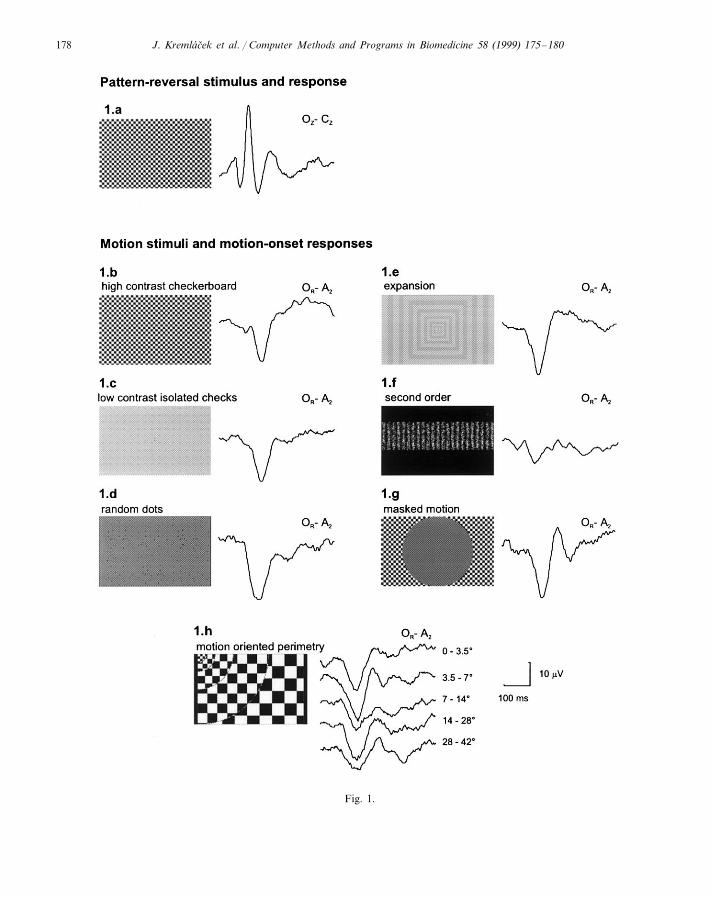
Regular checkerboard of 40 arc min checkswith the mean luminance of 17 cd/m2 and 96%contrast was used. The pattern reversal rate was1 Hz, i.e. two reversals per second. The stimulusFLI file occupied 76 kB. The response to thestimuli is presented in Fig. 1(a).
J. Kremlac' ek et al. / Computer Methods and Programs in Biomedicine 58 (1999) 175–180178
Fig. 1.

J. Kremlac' ek et al. / Computer Methods and Programs in Biomedicine 58 (1999) 175–180 179
4. Motion-onset stimuli
Our laboratory is specialised in an examinationof the magnocellular pathway, using various kindsof motion oriented stimuli [5–7]. Some of themare presented in the following text. Common stim-ulus timing used in all stimuli is �200 ms (14frames) of the movement and 1 s of the inter-stim-ulus interval. Mean luminance is kept at 17 cd/m2.
(1) High contrast checkerboard. This is a regu-lar high contrast (96%) 40 arc min checkerboardmoving with a velocity of 10°/s. The evoked po-tential (EP) differs substantially from the pattern-reversal EP—a dominant negative peak at �160ms seems to be specific for perception of motiononset (Fig. 1(b)).
(2) Low contrast isolated checks. The grey, 10%of contrast structure moving in four cardinal di-rections with 20°/s velocity is created as a net ofisolated, darker, 20 arc min checks (with 60 arcmin distance between each other) on brighterbackground. The size of the FLI file is 170 kB(Fig. 1(c)).
(3) Single moving dots represent very strongstimulus for subjects with sufficient visual acuity.The 5 arc min dots move coherently in squares (6°edge) with the velocity of 10°/s. The four funda-mental directions of motion are combined not tobe the same in any of neighbourhood squares.Between the following stimuli the motion direc-tion is changed in pseudorandom way in onesquare. The FLI animation is saved in 233 kB file(Fig. 1(d)).
(4) Expanding structure. This is a stimulus verypowerfully capable of evoking the motion-onsetresponses in almost whole population consists of
expanding, 10% contrast grey frames. The framesare increasing in the width toward the peripheryfrom 20 to 210 arc min and also the velocityincreases in the same manner from 10 to 80°/s.The FLI file is �53 kB and for typical EP, seeFig. 1(e).
(5) Second order motion-animation is also aconvenient style for many psychophysical exami-nations. The EP in Fig. 1(f) was recorded as aresponse to texture–contrast modulated gratingmoving at 10°/s velocity. A little different shapeof response is caused by the fact that anothersubject sat for this examination. The FLI file took�345 kB of disk space.
(6) Masked motion. This animation techniqueoffers a simple way to create any masked stimulifor selective examination of the visual field. Thestimulus parameters for EP displayed in Fig. 1(g)are the same as in the case of the high contrastmoving checkerboard but here the central 20° ismasked.
A specific application of the masking representsa whole visual field examination, i.e. the perime-try. One quadrant stimulus and motion-onsetVEPs based objective perimetry is presented inFig. 1(h). The stimulus contains five concentricfields with decreasing spatial frequency (increasingchecks size 40–200 arc min) and increasing mo-tion velocity (10–50°/s) from the centre towardthe periphery.
5. Conclusion
The choice of the FLI-widely spread animationfile format with existing interactive graphics editor
Fig. 1. Visual evoked responses recorded to stimuli generated by proposed stimulator are listed together with screen snapshots ofgiven stimuli: (a) the pattern reversal stimulus and EP with dominant positive peak. The response was recorded from bipolar leadOz–Cz; (b) the linear motion stimulus of the same spatial characteristic as (a) ones with EP recorded to onset of stimulus motionoffer different information describing mainly the magnocellular system. Negative components at �160 ms is characteristic formotion–onset oriented response. The unipolar EP was recorded from the right lateral occipital lead Or (5 cm from Oz); (c) linearmotion of 10% contrast structure in one of four directions (in pseudorandom order) also gives the motion oriented negativity; (d)stimulus screen consisting of 24 squares of coherently moving dots is another efficient motion–onset stimulus; (e) 10% contrastexpanding structure, the most efficient stimulus, with increasing velocity, a decreasing spatial frequency toward the periphery; (f)second order motion elicited smaller, but distinct negativity. Stimulus was created as contrast modulated texture driven in onedirection; (g) 20° central mask of motion structure evokes a regular negative response (see (b)); (h) the consequently stimulatedannual fields of the right down quadrant of visual field with eccentricities up to 42° produce the motion response even in the mostperipheral stimulation part. The stimulus represents one quarter of the objective motion oriented perimeter.

J. Kremlac' ek et al. / Computer Methods and Programs in Biomedicine 58 (1999) 175–180180
autodesk animator supports the idea of easy de-velopment of new stimuli, however the availableplayers are not able to generate trigger. The newsolution for visual stimulation introduced herebrings several benefits: (1) possibility of variousstimuli, i.e. no problem with disparate motion,masking, non-linear velocity; (2) fast stimulus re-alisation and its easy modification; (3) multipletrigger possibility; (4) cheap non-single task stim-ulation device; and (5) the possibility of sharingthe same stimuli among laboratories and a quickintroduction into the clinical practice.
The selection of this animation technique isbalanced by relatively low resolution 320×200pixels (enable enough fast graphics on widelyaccessible computers).
The player TFLI is available free of charge onrequest at the following e-mail (mail) address:[email protected].
Acknowledgements
This work was supported by a grant from theGrant Agency of Charles University (grant No.56/97/C /LF HK), Grant Agency of Czech Re-
public (No. 309/96/0959), Grant Agency of Min-istry of Health of Czech Republic (No. 3230-3/95,2980-3) and by James S. McDonnell, Foundationfor Cognitive Neuroscience.
References
[1] D.Y. Amamoto, M. Ariel, A low-cost VGA-based visualstimulus generation and control system, J. Neurosci. Meth-ods 46 (1993) 147–157.
[2] M.S. Bradnam, A.L. Evans, D.M.I. Montgomery, et al., Apersonal computer-based visual evoked potential stimulusand recording system, Doc. Ophthalmol. 86 (1994) 81–93.
[3] F. Vıt, M. Kuba, J. Kremlaeek, Z. Kubova, M. Horevaj,Video-signal synchronises registration of visual evoked re-sponses, Acta Med. 39 (1996) 115–116.
[4] R.F. Ferraro, Programmer’s Guide to the EGA, VGA andSuper VGA Cards, 3rd ed., Addison-Wesley, Reading,MA, 1994.
[5] Z. Kubova, F. Vıt, M. Kuba, Comparison of visual evokedresponses to the onset of pattern movement and to thereversal stimulation, Electroencephalogr. Clin. Neurophys-iol. 72 (1989) 70.
[6] Z. Kubova, M. Kuba, J. Hubaeek, F. Vıt, Properties ofvisual evoked potentials to onset of movement on a televi-sion screen, Doc. Ophthalmol. 75 (1990) 67–72.
[7] Z. Kubova, M. Kuba, Clinical application of motion-onsetvisual evoked potentials, Doc. Ophthalmol. 81 (1992) 209–218.
.