simple 440 mhz yagi antennas - dcarc.clubdcarc.club/2016 n8pr 440 mhz yagi.pdf · design criteria...
TRANSCRIPT

Simple 440 MHZ
Yagi Antennas
By Pete Rimmel N8PR


But FIRST:
Let’s talk a bit about satellite tracking
since questions were asked on the last
“RF” net on Thursday
The most info can be obtained at:
www. amasat. org


Orbitron from:
www. stoff. pl

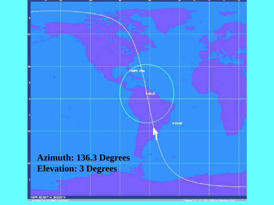
Azimuth: 136.3 Degrees
Elevation: 3 Degrees

Azimuth: 071.7 Degrees
Elevation: 26.3 Degrees

Azimuth: 007.3 Degrees
Elevation: 3 Degrees


AND NEXT:
Before we talk about the yagi antennas
lets talk about how to make your
handi-talkie work better:

How about that !
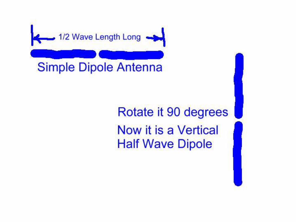
Your Rubber Duckie can
be Half of the Dipole…
just clip on a ¼ wave
long wire to the ground
side of the BNC and you
have a more effective
antenna !
For 2 meters this wire is
about 19 ½ inches long.
That will work for 440
as well – or clip on a
6” wire as on the right.

AND N-O-W
On to the 440 MHz Yagi
antennas !

Design criteria for a simple 440 MHz antenna:
They can be made using various materials and in varous sizes.
We want to keep the design simple.
We want to use readily available materials.
We want enough forward gain to hit the local repeater.
We want enough beam width so aiming is not critical.
It must be inexpensive.
We will look at two antennas a 4 element and 6 element yagi

The BOOM:
The boom can be made from ANY NON-METALLIC material.
We do not want to use aluminum or we will have to change
the dimensions that we have – and mounting will be much more
difficult, since we would then have to isolate the driven element.
Wood is easy to work with, but not weather resistant.
½ inch PVC pipe and couplings are our best choice.

The ELEMENTS:
Wire coat hangars (for inside use – they will rust)
#8 Copper wire ~1/8” diameter - cheap and available
(from Home Depot)
1/8 Inch aluminum tube or aluminum welding rod
(local aluminum supplier)
Bronze brazing rod (welding supplier)
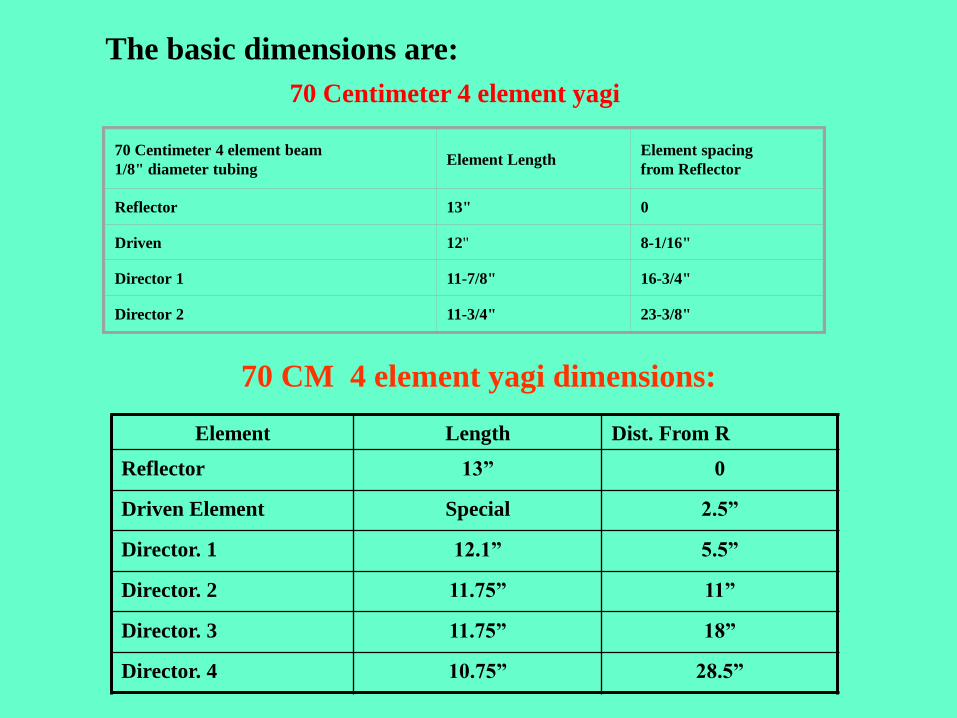
70 Centimeter 4 element yagi
70 Centimeter 4 element beam
1/8" diameter tubing Element Length
Element spacing
from Reflector
Reflector 13" 0
Driven 12" 8-1/16"
Director 1 11-7/8" 16-3/4"
Director 2 11-3/4" 23-3/8"
The basic dimensions are:
Element Length Dist. From R
Reflector 13” 0
Driven Element Special 2.5”
Director. 1 12.1” 5.5”
Director. 2 11.75” 11”
Director. 3 11.75” 18”
Director. 4 10.75” 28.5”
70 CM 4 element yagi dimensions:

433.92 MHz Yagi Antenna - Unknown Author
Drill or cut a small hole in to the bicycle hand grip so that the BNC connector will fit. Pass the coax through the hole, leaving the BNC connector's
base in the hole. Using the nut that came with the BNC connector, affix the connector to the bicycle hand grip.
Push the hand grip on to the wood on the end closest to the Ref (reflector). As you push the hand grip onto the wood, maneuver the coax so that it
ends up on the same side of the wood as the short section on the DE (driven element). Don't push the hand grip too far or you'll crush the coax / BNC
connection. You may need to shim the inside of the hand grip with another piece of wood in order to achieve a tight fit between the hand grip and the
wood (I used some of the wood that I had cut off ealier to shim the handle).
Route the coax down along side the wood to the DE. Trim the end of the coax so that you'll be able to solder the center conductor to the end of the
short end of brass rod and the coax shied to the longer length (see the drawing). Tin the brass rod at the end of the short end and the long end next to
the wood. Solder the coax to the DE (see the drawing). Add a dab of epoxy or CA if necessary to hold the DE in
place.
That's all there is to it! Your antenna is complete and ready to use. If you want to further tune the antenna, the mounting point of the center conductor
has an effect on the rf resistance of the antenna. The tip of the DE furthest from the bend can be trimmed for resonance. However, using the
measurements I've given, without further tuning, will produce an antenna close enough to resonance and 50 ohm resistance that further tuning may
not be necessary as long as you use the antenna for recieving only (no transmitting).
Mark also suggested I bake the yagi in a low temp oven for a day or so to drive all moisture out of the wooden boom, then give it a coat of clear
lacquer. Go back
What are the differences?
4 Element yagi has less gain (~8 dBi) but a wider
beamwidth for a wider pattern
6 Element yagi has more gain (~11 dBi) but is
narrower and needs more precise aiming.
4 element yagi pattern 6 element yagi pattern

4 element yagi easy to build and
feed directly with 50 ohm coax.
Center of boom has no element
and makes for easy mounting.
6 el. Yagi a bit more work to
build. Directly fed with 50 ohm
coax
Must decide where the balance
point is for mounting.

NOTE: Coax must be led
away from the antenna
at 90 degrees from the
boom and elements.
If led from the driven
element to the back, it
still must leave the
antenna at 90 degrees
from the elements.

The driven element can be straight or in a half folded
dipole configuration. Either way it is fed directly
with 50 ohm Coax.

There are many ways to
bend the driven element.
The important thing is to
have the two parts parallel
and spaced correctly when done.

One way to assure proper spacing
is to solder the loop part of the
driven element directly to a coax
or other connector before inserting
it into the boom.
Draw a line the length
of the boom to use as
a guide for drilling the
element holes.
BE SURE the holes are
all lined up or your
elements will be crooked on the boom.


Let’s build an antenna !

First measure
and cut some
wire or rod to
the dimensions
we need.
70 Centimeter 4 element beam
1/8" diameter tubing Element Length
Element spacing
from Reflector
Reflector 13" 0
Driven 12" 8-1/16"
Director 1 11-7/8" 16-3/4"
Director 2 11-3/4" 23-3/8"

Prepare the driven element leaving a ¼” gap. Tape it and
secure it with heat shrink. You may have to re-cut the
element to length.
Be sure to re-measure it after this step.

Drill the PVC boom and insert the elements. Note the
‘TEE’ in the middle for mounting the antenna.

PEPARE THE FEED LINE:
Remove 1” of the outer cover of your
Coax - RG-58 or RG-8X 50 Ohm Coax
With a pointed tool, comb out the
Braid away from the cener conductor.
Twist and tin the braid. Cut 3/8”
Off the center insulation and tin
The center conductor.
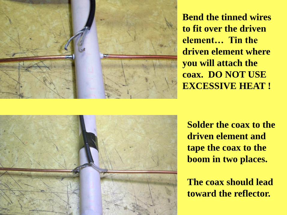
Bend the tinned wires
to fit over the driven
element… Tin the
driven element where
you will attach the
coax. DO NOT USE
EXCESSIVE HEAT !
Solder the coax to the
driven element and
tape the coax to the
boom in two places.
The coax should lead
toward the reflector.

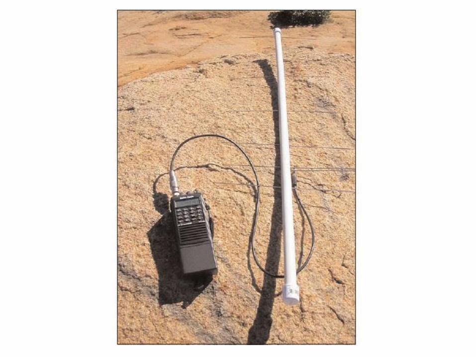
Here’s the finished antenna…
Any questions???


http://www.qsl.net/w4sat/antlegn.htm
References:
http://www.tristantech.net/articles/yagi/1.php
http://picaxe.orconhosting.net.nz/yagi433.jpg
http://www.nr6ca.org/70cmyagi.html
http://www.amsat.org/amsat-
new/information/faqs/crow/JulAug06AmsatJournal.pdf
Thank you for your interest.
See you (hear you) on the repeater !
73 de N8PR