simcommsys: taking the errors out of error-correcting code ... · simcommsys: taking the errors out...
TRANSCRIPT

SimCommSys: taking the errors out of error-correcting code simulations
Johann A. Briffa, Stephan Wesemeyer
Department of Computing, University of Surrey, Guildford GU2 7XH, EnglandE-mail: [email protected]
Published in The Journal of Engineering; Received on 20th February 2014; Accepted on 12th May 2014
Abstract: In this study, we present SimCommSys, a simulator of communication systems that we are releasing under an open source license.The core of the project is a set of C + + libraries defining communication system components and a distributed Monte Carlo simulator. Ofprincipal interest is the error-control coding component, where various kinds of binary and non-binary codes are implemented, includingturbo, LDPC, repeat-accumulate and Reed–Solomon. The project also contains a number of ready-to-build binaries implementing variousstages of the communication system (such as the encoder and decoder), a complete simulator and a system benchmark. Finally,SimCommSys also provides a number of shell and python scripts to encapsulate routine use cases. As long as the required componentsare already available in SimCommSys, the user may simulate complete communication systems of their own design without any additionalprogramming. The strict separation of development (needed only to implement new components) and use (to simulate specific constructions)encourages reproducibility of experimental work and reduces the likelihood of error. Following an overview of the framework, we providesome examples of how to use the framework, including the implementation of a simple codec, the specification of communication systemsand their simulation.
1 Introduction
Error-correcting codes are everywhere, from CDs (using Reed–Solomon codes), the now interstellar space communicationbetween NASA and the Voyager 1 probe (using a convolutionalcode concatenated with a Golay code), to current terrestrial HDTVbroadcasts (DVB-T2, using concatenated low-density parity-check(LDPC) and BCH codes). Shannon’s seminal paper [1] showedthat almost error-free communication is possible provided the rateof the information transmitted is below the capacity of the channel.Unfortunately, the proof is based on a probabilistic argument anddoes not provide a way of constructing codes that achieve thechannel capacity while still being practical to encode and decode.Since then, the error-correction code community has developed aplethora of different codes and associated encoders and decoders.Modern codes, such as turbo [2], LDPC [3] and polar codes [4],have come very close to the channel capacity while still havingencoders and decoders ‘simple’ enough to be useful.As new codes continue to be developed whose performance need
to be evaluated, most researchers in this field will at some pointhave written a simple test and performance measurement harness.To do this, it is likely they will have needed to implement or findat least: (a) a fast finite field representation for their code alphabet,(b) vector and matrix representations capable of handling finitefields for their encoder and decoder, (c) a channel implementationto simulate the transmissions of codewords, (d) a framework thatglues together the encode, transmit, decode steps for a largenumber of codewords and computes the symbol error rate (SER)and frame error rate (FER) and (e) for more complex systems, away of using this framework on a cluster to speed up the processingtime. Although being able to code these things is arguably a goodlearning experience for any new researcher, most of these imple-mentation tasks are peripheral to the main research problem ofdesigning codes.These elements are needed to test the code, but should be inde-
pendent of the code and remain unchanged across codes. In fact,researchers having to implement these components separately is alikely source of additional errors which might hide problems inthe performance of the designed code. For example, a channelwhich introduces less noise than required for a specificsignal-to-noise ratio (SNR) might boost the claimed performanceof a code. Consequently, having a framework of well-tested
J Eng 2014doi: 10.1049/joe.2014.0055
This is an openAttribution-
components that provide all the required features allows theresearcher to concentrate on code design and testing it. It also pro-vides other researchers with a means to reproduce the results moreeasily.
Current choices for researchers are limited, and each option hasits caveats. Perhaps the most popular solution, MATLAB [5] andits Communications Toolbox includes implementations of a verywide range of current schemes. However, it comes at a considerablefinancial cost, particularly for parallel computation, limiting itsavailability to researchers. Furthermore, its usual workflow requiresthe user to write scripts to describe a given system, making it easy tointroduce logical errors. The interpreted nature of the language alsomakes the implementation of novel code constructions inefficient,unless one makes use of the MATLAB to C/C + + interface(which requires considerable technical skill). An alternative open-source solution exists in the form of IT + + [6, 7], a library of math-ematical, signal processing and communication system compo-nents. Although this library includes implementations of mostcurrent schemes, it is designed to be used by programmers, andthe implementation of a system requires the user to write C + +code. Notably, the library does not include a simulation framework,so that the user is responsible to collect results and decide when asimulation has converged.
Our simulator of communication systems (SimCommSys) C + +framework helps address all these issues. It runs on both Windowsand Linux and can also use NVIDIA GPUs using CUDA [8]. It hasbeen developed over more than 15 years by the first author and wasused successfully in a number of papers [9–13]. The source codehas been released under the GNU General Public Licence version3 (or later) and can be found, together with its documentation, at:https://github.com/jbresearch/simcommsys.
Researchers are provided with a host of existing codecs, channels,modulators and different performance measures to gather resultsquickly. Furthermore, the implementation is highly modular andevery component is designed around simple-to-use interfaceswhich make it straightforward to extend the framework with newcodecs as well as other components like channels, modulators etc.as required. Particular attention is also paid to the correctness of im-plementation and verifiability, for increased confidence in the resultsobtained. Internal checks are performed at multiple levels, and areavailable to the user through the debug build.
access article published by the IET under the Creative CommonsNonCommercial-NoDerivs License (http://creativecommons.org/
licenses/by-nc-nd/3.0/)1
The rest of this paper is organised as follows. In Section 2, wedescribe the structure of the framework in more detail, highlightingthe main components of interest. This is then followed by someexamples of how to use SimCommSys in Section 3 and how toextend the framework in Section 4. We conclude with an invitationto other researchers to use and contribute to the project.
2 SimCommSys: the framework
2.1 Communication system model
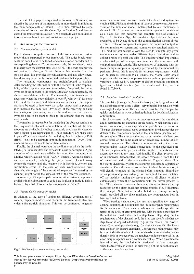
Fig. 1 shows a simplified version of the communication systemmodel that is supported by our framework. The codec block repre-sents the code that is to be tested, and consists of an encoder and itscorresponding decoder. To create a new code, the user simply needsto inherit from the abstract class codec or, if the code can providesoft output, codec_softout. In turn this inherits from thecodec class; it is provided for convenience, and also allows itera-tive decoding between the codec and modems that support this.
The remaining components are straightforward to explain.After encoding the information with the encoder, it is the responsi-bility of the mapper component to translate, if required, the outputsymbols of the encoder to the symbols that can be modulated by thechosen modulation scheme. For example, this translation isnecessary when the code alphabet is over Fq with q = 2k for somek > 1, and the channel modulation scheme is binary. The mappercan also be used to interleave the codec output and to punctureit to increase the code rate. Obviously, at the receiving end anyinterleaving or puncturing needs to be undone and the receivedsymbols need to be mapped back to the alphabet that the codecunderstands.
The modem is responsible for translating the abstract symbols totheir equivalent channel representation. A number of differentmodems are available, including commonly used ones for channelswith a signal-space representation. These include M-ary phase-shiftkeying (PSK) with variable M [including M = 2 for binary PSK(BPSK) etc.] and quadrature amplitude modulation (QAM). Nullmodems are also available for abstract channels.
Finally, the channel represents the medium over which the modu-lated signal is transmitted and exposed to noise or corruption. Againa number of channels are available, including the commonly usedadditive white Gaussian noise (AWGN) channel. Abstract channelsare also available, including the q-ary erasure channel, q-arysymmetric channel and also channels with insertion, deletion andsubstitution errors. In the case of such synchronisation errorchannels, the length of the transmitted sequence (i.e. entering thechannel) might not be the same as that of the received sequence.
A summary of the principal communication system componentsavailable in the SimCommSys code base is given in Table 1. This isfollowed by a list of codec sub-components in Table 2.
2.2 Monte Carlo simulator model
In addition to the ease of setting up different combinations ofcodecs, mappers, modems and channels, the framework also pro-vides a feature-rich simulator. This can be configured to gather
Fig. 1 SimCommSys communication system model
This is an open access article published by the IET under the CreativeAttribution-NonCommercial-NoDerivs License (http://creativecommonlicenses/by-nc-nd/3.0/)2
numerous performance measurements of the described system, in-cluding SER, FER and the timings of various components. An over-view of the simulator model implemented by our framework isshown in Fig. 2, where the communication system is consideredas a block box that performs the complete cycle of events ofFig. 1. In SimCommSys, the simulator object defines the inputsequences to be cycled through the communication system object;a results collector component compares the input and output ofthe communication system and computes the required statistics.This modular architecture allows the user to simulate any givencommunication system under different input conditions and tocollect a range of possible results. The simulator object implementsa substantial part of the experiment interface: that concerned withcomputing a single sample. The accumulation of aggregate statisticsfrom multiple samples is typically performed by the binomial ex-periment object; this is suitable for error-rate experiments, whichcan be seen as Bernoulli trials. Finally, the Monte Carlo objectimplements the necessary loops to obtain enough samples until con-vergence is achieved. A summary of classes providing simulationtypes and related facilities (such as results collectors) can befound in Table 3.
2.3 Local or distributed simulation
The simulator (through the Monte Carlo object) is designed to workin a distributed setup using a client–server model, but can also workas a single local process. The latter mode is useful, for example, forquick simulations or when gathering timings for benchmarking andoptimisation.
In client–server mode, a server process controls the simulationand is responsible for gathering all the results. When starting a dis-tributed simulation, the user specifies the port the server listens on.The user also passes a text-based configuration file that specifies thedetails of the components needed in the simulation (see Section 3for examples). The user can then start any number of client pro-cesses either on the same machine or across any number of net-worked computers. The clients communicate with the serverprocess using TCP/IP socket connections to the specified port.The server process keeps track of the number of clients and canaccept new ones at any time. Additionally, if a client process diesor is otherwise disconnected, the server removes it from the listof connections and is otherwise unaffected. Together, these allowthe user to dynamically scale the resources allocated to a particularsimulation. Once the server process has finished the simulation, itwill cleanly terminate all the clients before stopping. Should theserver process stop inadvertently, for example if the user switchedoff the machine running the server process, all clients terminateautomatically when their connection with the server process islost. This behaviour prevents the client processes from using upresources on the client machines unneccessarily. Fig. 3 illustratesthis principle. Note that in the distributed case, timings are onlyuseful provided all the client machines are homogeneous both inhardware and software.
When starting a simulation, the user also specifies the range ofchannel conditions to be simulated and the convergence requirementsfor the simulation. The channel conditions are usually specified interms of the SNR or error probabilities, with the range specified bythe initial and final values and a step factor. Depending on therequirements of the channel used, the user can specify whether thestep factor is applied additively (e.g. in the case of the AWGNchannel) or multiplicatively (e.g. for abstract channels like inser-tion–deletion or erasure channels). Convergence requirements maybe specified as the number of error events to be accumulated (conven-tionally 100) or by specifying the required confidence interval (as anerror margin together with a confidence value). When a confidenceinterval is set, the simulation is considered to have convergedwhen the true value is within the error margin of the current estimate,at the stated confidence level.
Commonss.org/
J Eng 2014doi: 10.1049/joe.2014.0055

Table 1 Summary of the principal communication system components available in the code base
Base Class Description
codec reedsolomon Reed-Solomon code over Fq of length n∈ {q, q− 1} and dimension 1 < k < n− 1 with Berlekamp decoderldpc LDPC code over Fq of length n and dimension mmapcc convolutional code with BCJR decoder [14]repacc repeat-accumulate code with BCJR decodersysrepacc systematic repeat-accumulate code with BCJR decoderturbo parallel concatenated convolutional code with variable interleavers and BCJR decodermemoryless simple mapping, with or without repetitionuncoded uncoded transmission (output is copy of input)codec_multiblock meta-codec that concatenates a number of blocks of the underlying codec (for interleaving across blocks)codec_concatenated meta-codec that concatenates a sequence of codecs (with intermediate mappers)
blockmodema dminner sparse inner codes with distributed marker sequence and Davey–MacKay decoder [15]marker marker codes with bit-level MAP decoder [16]tvb time-varying block codes with GPU-enabled symbol-level MAP decoder [9, 17]
mapper map_straight each modulation symbol encodes exactly one encoder symbolmap_interleaved random interleaving of symbols within the blockmap_permuted random permutation of symbols at each indexmap_aggregating each modulation symbol encodes more than one encoder symbol (e.g. binary codecs on q-ary modems)map_dividing each encoder symbol is represented by more than one modulation symbol (e.g. q-ary codecs on binary modems)map_stipple punctured mapper for turbo codes, with all information symbols transmitted and parity symbols taken
from successive sets; equivalent to odd/even puncturing for two-set turbo codesmap_concatenated meta-mapper that concatenates a sequence of mappers
blockmodem direct_blockmodem abstract q-ary channel modulationM-ary phase shift
keying
MPSK modulation with Grey code mapping of adjacent symbols in constellation
qam quadrature amplitude modulation for square constellations with Grey code mapping of adjacent symbols
channel awgn additive white Gaussian noise channel (for signal-space modulations)laplacian additive Laplacian noise channel (for signal-space modulations)qec q-ary erasure channel (for abstract modulations)qsc q-ary symmetric substitution channel (for abstract modulations)qids q-ary insertion, deletion and substitution channel (for abstract modulations)bpmr bit-patterned media recording channel of [18]
aThe encoders/decoders in this section are implemented using the blockmodem interface because of the required access to the channel, which is onlyavailable through the blockmodem interface.
Once the server process is up, all that any client process requiresis the hostname or IP address of the server process and the portnumber it is listing on. On connection, the server sends thesystem configuration to the client together with the channel
Table 2 Summary of available codec sub-components
Base Class
fsma dvbcrsc circular recursive systematic congnrcc non-recursive convolutional codgrscc recursive convolutional code ovnrcc binary non-recursive convolutiorscc binary recursive convolutional czsm a zero-state machine or in othercached_fsm meta-fsm that pre-computes and
interleaverb flat null interleaver (usually used foberrou the original turbo code interleavhelical helical interleaver [20]rectangular simple rectangular interleavershift_lut circular-shifting interleavernamed_lut a general interleaver specified auniform_lut random interleaver (with uniforrand_lut random interleaver with simileonetimepad interleaver that performs symbopadded meta-interleaver that concatenat
aThis class implements a finite state machine interface, which is used to specify ththe mapcc and turbo classes; it is also used to specify the accumulator in repbThis class implemented the interface for the interleaver used in parallel concatena
J Eng 2014doi: 10.1049/joe.2014.0055
This is an openAttribution-
parameter to simulate. Each client seeds its random generatorwith a true random value from the OS. This ensures that allclients simulate different random input sequences, noise patternsand (for applicable systems) different random system components
Description
volutional code from the DVB standard [19]e over Fq with encoder polynomials expressed in controller-canonical former Fq with encoder polynomials expressed in controller-canonical formnal code with encoder polynomials expressed in controller-canonical formode with encoder polynomials expressed in controller-canonical formwords a repeatercaches the input/output table of its component fsm
r the first parity sequence)er of [2]
s a look-up table (generated externally)m distribution)property [20]l-by-symbol modular addition between input and a random sequencees any interleaver with a onetimepad
e encoder in a convolutional code. This is needed for obvious reasons inacc and the mapping in memoryless.ted convolutional codes, creating diversity between the parity sequences.
access article published by the IET under the Creative CommonsNonCommercial-NoDerivs License (http://creativecommons.org/
licenses/by-nc-nd/3.0/)3

Fig. 2 SimCommSys simulator model
Fig. 3 SimCommSys client–server model
(e.g. random interleavers). The client instantiates all the necessarycomponents and runs the simulation sending results back to theserver process regularly. The server process aggregates resultsfrom all clients, and stores these in a human-readable text file.Intermediate results (i.e. aggregate results that have not yet con-verged) are stored regularly on file, with the full state of the simula-tion. This allows the server to continue a previously terminatedsimulation, and mitigates the risk of server failure on long-runningsimulations. The code base provides a python module and asimple script which can be easily modified to present the resultsgraphically using the matplotlib library [22].
In all of the above, the only programming required by the user isthe implementation of any new components and a simple adaptationof the python script to visualise the results if required. All the otheraspects of the simulation are taken care of by the framework. In thenext section, we will demonstrate how to set up a system and run asimulation.
Table 3 Summary of classes providing simulation types and related facilities (suc
Base Class
experiment_binomiala commsys_simulator generic siuser-speciparameter
commsys_stream_simulator variation oreception,priori and
commsys_threshold variation othe modemin this obj
experiment_normalb commsys_timer meta-expecommunic
results collectorc errors_hamming conventioerrors_levenshtein as for err
metric [21fidelity_pos computati
synchronihist_symerr computesprof_burst determine
a correctlydetermine
prof_pos computesprof_sym computes
aImplements the interface for an experiment where a binomial proportion is estimabImplements the interface for an experiment where the samples take a normal distcAlthough there is no base class, the interface is specified in commsys_simula
collected in a given simulation.
This is an open access article published by the IET under the CreativeAttribution-NonCommercial-NoDerivs License (http://creativecommonlicenses/by-nc-nd/3.0/)4
3 Using SimCommSys
3.1 Running a quick simulation with a simple codec
The most common use case is to set up and simulate a communica-tion system under a range of channel conditions. This starts with thespecification of a simulation based on a communication system, de-fining the mapper, modem and channel to be used as well as whatresults we want to gather. The file shown in Fig. 4 is an example ofhow to achieve this for a very simple setup: an uncoded BPSKtransmission over AWGN. As can be seen from the config file,each component has its own heading followed by a number of para-meters. A version number is usually included to allow old configur-ation files to be read provided the newer version of the serialisationcode can provide default values for any missing or changed para-meters. The file format allows the inclusion of comments, indicatedby lines starting with a #, which are skipped when the file is read.
h as results collectors)
Description
mulator of communication systems, supporting random, all-zero orfied input sequences and a modular results collection interface; simulationspecifies channel conditionsn commsys_simulator that simulates stream transmission andwhere the start and end of each frame are not assumed to be known aare instead estimated by the receivern commsys_simulator where the simulation parameter specifiesthreshold setting; the channel conditions are fixed to a value specified
ect
riment to determine timings of individual components of a givenation system
nal SER and FER computed using the Hamming distance metricors_hamming, with additional SER computed using the Levenshtein]on of the fidelity metric at frame and codeword boundary positions, forsation error-correcting codeshistogram of symbol error count for each block simulateds the error probabilities for the first symbol in a frame, a symbol following-decoded one, and a symbol following an incorrectly decoded one; used tothe error burstiness profilesymbol-error histogram as dependent on position within blocksymbol-error histogram as dependent on source symbol value
ted, approximating the error with a normal distribution.ribution, and the mean of the distribution needs to be estimated.tor, where objects of this type are used to specify the results to be
Commonss.org/
J Eng 2014doi: 10.1049/joe.2014.0055

Fig. 4 Uncoded BPSK transmission over AWGN
Fig. 6 Simulation output for uncoded BPSK transmission over AWGN
In this example, we are simulating a communication system witha signal-space channel representation and gathering error ratesusing the Hamming distance. Within the simulator we can specifywhether an all-zero, random or user-specified information sequenceshould be used. The actual communication system starts with theuncoded class defining a binary code of length 16 320 bits.This is passed through a straight mapper (i.e. left unmodified)and modulated with a PSK modem of alphabet size 2 (i.e. aBPSK modem). The result is transmitted on an AWGN channel.Note that the communication system allows us to define separatechannel objects for the transmit and receive functions. This isunused here, and would allow us to simulate the system with a mis-matched receiver.The user can test the system file by simply running a short simu-
lation using the ‘QuickSimulation’ command as shown in Fig. 5.This will run the simulation at an SNR of 6.8 dB for ten seconds.The final output should look something like Fig. 6. This outputalso allows us to determine the speed at which a simulation ofthis code runs. For this simple codec, the simulator computed135.8 frames of 16 320 bits each per second, equivalent to 2.22Mbit/s (on an Intel Core i5-3570K central processing unit using asingle core at 3.4 GHz).
3.2 Quick simulation of a more complex system
Consider next a more complex system with a Reed–Solomon codein concatenation with a convolutional code, as used in the NASAVoyager mission [23, 24]. The corresponding configuration file isshown in Fig. 7. This defines a serially concatenated construction,as follows. The outer code is a (255, 223) Reed–Solomon codedefined over F256 (using the reedsolomon component). Arandom interleaver operates over four successive outer codewords,so that any burst errors are distributed across four codewords
Fig. 5 Running a short simulation
J Eng 2014doi: 10.1049/joe.2014.0055
This is an openAttribution-
(achieved using the map_interleaved component). The innercode is a rate-1/2 convolutional code, specified by the feedforwardpolynomials 1 + z−2 + z−3 + z−5 + z−6 and 1 + z−1 + z−2 + z−3 + z−6.In the serialised file, these are represented by the strings1011011 and 1111001. The Reed–Solomon encoder output isconverted from F256 to F2 (binary) using the map_dividingcomponent. The output of four Reed–Solomon codewords isequivalent to 8160 bits; this is terminated with six tail bits beforeencoding with the convolutional code. The mapcc componentuses the BCJR algorithm [14], minimising SER. The outputfor this code at an SNR of 2.2 dB after ten seconds isshown in Fig. 8. Note that this corresponds to a decoding speedof 36.9 kbit/s which is about sixty times slower than the uncodedtransmission.
3.3 Running a proper simulation
Having tested the simulator configuration files and verified that theyare working, it is now a simple step to start a simulation. For theuncoded system, this can be done as shown in Fig. 9. This startsthe server process, listening on port 9000. The simulation startswith the channel SNR at 1.5 dB and works its way up to 11 dBin steps of 0.1 dB. The point at which the simulation switches tothe next SNR value is determined by the convergence requirements,which can be specified either in terms of the number of error eventsencountered or as a confidence interval. In this case, we specify anerror margin of ± 5% at a 95% confidence level.
In this example, the simulation stops completely when at leastone of the measures (SER or FER in this case) has fallen below10−5. Note that this can and usually should occur well before allnoise values have been explored. Alternatively, the user can set--floor-max which would require all measures to fall belowthis threshold before the simulation stops. As SER≤ FER, ‘floor-min’ is usually used if the SER is more important to measurewhile ‘floor-max’ is used if the FER is the main focus.
Any number of clients can now be started using the commandshown in Fig. 10, where the server_address could belocalhost if the client is started on the same machine or alterna-tively the IP address or the DNS-resolvable name of the computerwhere the server process is running.
Repeating the same process for the concatenated system ofSection 3.2 and for a system with the inner convolutional codealone, we now have the necessary results to plot a performancecomparison, as shown in Fig. 11. The theoretical error rate for theuncoded AWGN channel is also shown, clearly coinciding withour simulation. For comparison, the figure also includes previouslypublished results from [24]. As expected, our simulation of the
access article published by the IET under the Creative CommonsNonCommercial-NoDerivs License (http://creativecommons.org/
licenses/by-nc-nd/3.0/)5
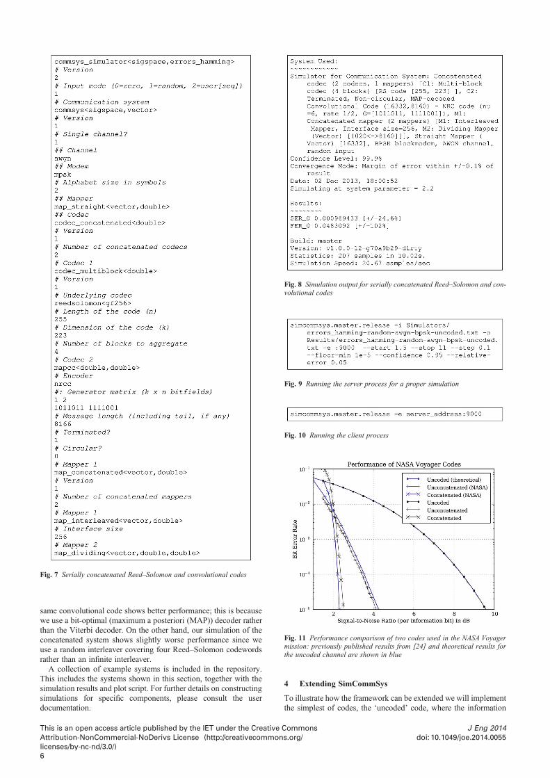
Fig. 7 Serially concatenated Reed–Solomon and convolutional codes
Fig. 8 Simulation output for serially concatenated Reed–Solomon and con-volutional codes
Fig. 9 Running the server process for a proper simulation
Fig. 10 Running the client process
Fig. 11 Performance comparison of two codes used in the NASA Voyagermission: previously published results from [24] and theoretical results forthe uncoded channel are shown in blue
same convolutional code shows better performance; this is becausewe use a bit-optimal (maximum a posteriori (MAP)) decoder ratherthan the Viterbi decoder. On the other hand, our simulation of theconcatenated system shows slightly worse performance since weuse a random interleaver covering four Reed–Solomon codewordsrather than an infinite interleaver.
A collection of example systems is included in the repository.This includes the systems shown in this section, together with thesimulation results and plot script. For further details on constructingsimulations for specific components, please consult the userdocumentation.
This is an open access article published by the IET under the CreativeAttribution-NonCommercial-NoDerivs License (http://creativecommonlicenses/by-nc-nd/3.0/)6
4 Extending SimCommSys
To illustrate how the framework can be extended we will implementthe simplest of codes, the ‘uncoded’ code, where the information
Commonss.org/
J Eng 2014doi: 10.1049/joe.2014.0055

Fig. 14 uncoded.cpp (decode)
sequence is transmitted as is and the received sequence is simplydecoded by taking a hard decision. This will illustrate several fea-tures and concepts of the framework without getting boggeddown in any implementation issues of an actual codec. To makethis exercise slightly more interesting, our implementationextends the codec_softout abstract class rather than the plaincodec abstract class. This class defines the interface for a soft-input, soft-output codec, and allows us to look at some of the fea-tures used by most modern codes.The main method that needs to be implemented for the encoding
is the do_encode method of Fig. 12. Note the use of templates inthe code fragment. Throughout the framework, templates are usedto provide support for a range of code alphabets and numerical pre-cisions with very little extra programming effort. The actual codealphabet and numerical precision are defined when the templatesare instantiated, and can be chosen at run-time as part of the serial-isation process.Decoding is implemented as a two-step process. First, the
decoder in initialised with the probabilities of the received se-quence. For a soft-input, soft-output codec, the methods that needto be implemented for this are the do_init_decodermethods of Fig. 13. Note that this method is overloaded, havingtwo implementations with different parameters. Therefore two var-iants of this method need to be implemented: one where only thechannel statistics for the received sequence are available andanother where prior probabilities for the transmitted sequence arealso given. The latter interface is required for systems involving it-eration between the modem and codec components.Next, the actual decoding takes place; this may be repeated a
number of times in an iteratively decoded code, where each succes-sive decoding makes use of information from previous decodings.For a soft-input, soft-output codec, the methods that need to beimplemented for this are the softdecode methods of Fig. 14.This method is also overloaded: the first implementation computesthe posterior probabilities of the decoded sequence only, whereasthe second one also computes the posterior probabilities of theencoded sequence. It is up to the calling class to decide which ofthese methods to use as there may be a computational cost in com-puting both values when only one is needed. For example, in thecase of turbo codes, only the probabilities of the informationsymbols are required as input to the next decoding stage, whereasthe probabilities of the parity check symbols are not required. On
Fig. 13 uncoded.cpp (init_decoder)
Fig. 12 uncoded.cpp (encode)
J Eng 2014doi: 10.1049/joe.2014.0055
This is an openAttribution-
the other hand, with LDPC codes the sum–product algorithmneeds to compute the probability of all symbols as everything isused in the next iteration.
The last two required functions provide serialisation support tothe codec. These allow the codec to be read in from file whensetting up a simulation, and also allow the server to send a serialisedversion of the system to be simulated to its clients. To achieve this,each component of the system needs to implement the followingtwo methods of the serialisable abstract class. In thisexample, the serialisable interface is inherited through thecodec and thus the codec_softout class. The first methodwrites the details of the codec to an output stream (e.g. a file or asocket), whereas the second method reads the necessary class para-meters (and components, where applicable) from an input stream.Both are shown in Fig. 15. Note that the libbase:eatcom-ments manipulator filters out any comments in the input stream.There are some more boiler-plate methods that need to be imple-mented, including methods to return a short description of thecodec and methods to return the length, dimension and alphabetsize of the code.
For such a templated class, the implementation file needs tocontain explicit instantiations of the different combinations of tem-plate parameters of the codec. Fig. 16 shows how Boost preproces-sor metaprogramming [25] is used to create the various instances ofthe templated codec which can then be serialised using the name of
Fig. 15 uncoded.cpp (serialise)
access article published by the IET under the Creative CommonsNonCommercial-NoDerivs License (http://creativecommons.org/
licenses/by-nc-nd/3.0/)7

Fig. 16 uncoded.cpp (boost)
the class. Finally, we must ensure that serialisation system ‘sees’ anobject of this type on startup: this is done by adding an object of thistype as a field or parent class of serializer_libcomm. Fortemplated classes, it is enough to include an object with any ofthe explicitly instantiated template parameters.
5 Conclusions
In this paper, we have presented SimCommSys, a simulator of com-munication systems released under an open-source license. Anoverview was given of the core of the project, a set of C + + librar-ies defining a number of communication system components and adistributed Monte Carlo simulator. The more common use case,where a communication system is defined and then simulatedusing the framework, was demonstrated. Finally, a tutorial forextending the framework was given, using the implementation ofan ‘uncoded’ codec as an example.
SimCommSys fills a current void, providing a reliable platformfor simulating communication systems without any additional pro-gramming (as long as the required components are already availablein SimCommSys). Development is only necessary when extendingthe framework by implementing new components. The strict separ-ation of development and the framework’s use to simulate specificconstructions encourages reproducibility of experimental work andreduces the likelihood of error.
The project has been in development for many years, and hasevolved to support changing requirements. For example, most re-cently the framework has been used to simulate codes for synchron-isation error channels, which as far as we know is not supported byany other publicly available software. We expect the project to con-tinue to evolve as the needs of its users change. The wider its userbase, the more comprehensive the software will become. We en-courage potential users to download and use the project in theirown research. Support is available through the project forum,whereas feature requests and bug reports may be submittedthrough the project tracker. Developers who wish to contribute to
This is an open access article published by the IET under the CreativeAttribution-NonCommercial-NoDerivs License (http://creativecommonlicenses/by-nc-nd/3.0/)8
the project are asked to contact the maintainer; communitysupport is welcome.
6 References
[1] Shannon C.E.: ‘A mathematical theory of communication’, Bell Syst.Tech. J., 1948, 23, pp. 379–423, 623–656
[2] Berrou C., Glavieux A., Thitimajshima P.: ‘Near Shannon limit error-correcting coding and decoding: turbo-codes’. Proc. IEEE Int. Conf.Communications, Geneva, Switzerland, May 1993, pp. 1064–1070
[3] MacKay D.J.C., Neal R.M.: ‘Near Shannon limit performance oflow density parity check codes’, Electron. Lett., 1997, 33, (6),pp. 457–458
[4] Arıkan E.: ‘Channel polarization: a method for constructingcapacity-achieving codes for symmetric binary-input memorylesschannels’, IEEE Trans. Inf. Theory, 2009, 55, (7), pp. 3051–3073
[5] Matlab: The language of technical computing’ (MathWorks, Inc.,2012). [Online]. Available at http://www.mathworks.co.uk/products/datasheets/pdf/matlab.pdf
[6] de Lima C.H.M., Stancanelli E.M.G., Rodrigues E.B., da S.MacielJ.M., Cavalcanti F.R.P.: ‘A software development framework basedon C + + OOP language for link-level simulation tools’. Int.Telecommunications Symp., 2006, pp. 597–602
[7] Cristea B.: ‘Turbo receivers with IT + + ’. Second Int. ICST Conf.Simulation Tools and Techniques. ACM, May 2010
[8] NVIDIA CUDA C Programming Guide, NVIDIA Corporation,October 2012, version 5.0
[9] Briffa J.A.: ‘A GPU implementation of a MAP decoder for synchron-ization error correcting codes’, IEEE Commun. Lett., 2013, 17, (5),pp. 996–999
[10] Buttigieg V., Briffa J.A.: ‘Codebook and marker sequence design forsynchronization-correcting codes’. Proc. IEEE Int. Symp.Information Theory, St. Petersburg, Russia, 31 July–5 August 2011
[11] Briffa J.A., Schaathun H.G.: ‘Improvement of the Davey–MacKayconstruction’. Proc. IEEE Int. Symp. Information Theory and itsApplications, Auckland, New Zealand, 7–10 December 2008,pp. 235–238
[12] Briffa J.A., Schaathun H.G.: ‘Non-binary turbo codes and applica-tions’. Proc. IEEE Int. Symp. Turbo Codes & Related Topics,Lausanne, Switzerland, 1–5 September 2008, pp. 294–298
[13] Briffa J.A., Buttigieg V.: ‘Interleavers and termination in unpuncturedsymmetric turbo codes’, IEE Proc. Commun., 2002, 149, (1),pp. 6–12
[14] Bahl L.R., Cocke J., Jelinek F., Raviv J.: ‘Optimal decoding of linearcodes for minimizing symbol error rate’, IEEE Trans. Inf. Theory,1974, 20, (2), pp. 284–287
[15] Davey M.C., MacKay D.J.C.: ‘Reliable communication over chan-nels with insertions, deletions, and substitutions’, IEEE Trans. Inf.Theory, 2001, 47, (2), pp. 687–698
[16] Ratzer E.A.: ‘Marker codes for channels with insertions and dele-tions’, Ann. Telecommun., 2005, 60, pp. 29–44
[17] Briffa J.A., Schaathun H.G., Wesemeyer S.: ‘An improved decodingalgorithm for the Davey–MacKay construction’. Proc. IEEE Int.Conf. Communications, Cape Town, South Africa, 23–27 May 2010
[18] Iyengar A.R., Siegel P.H., Wolf J.K.: ‘Write channel model forbit-patterned media recording’, IEEE Trans. Magn., 2011, 47, (1),pp. 35–45
[19] Digital Video Broadcasting (DVB); Interaction channel for satellitedistribution systems, ETSI, 5th September 2005, eN 301 790 v1.4.1
[20] Barbulescu S.A., Pietrobon S.S.: ‘Terminating the trellis of turbo-codes in the same state’, Electron. Lett., 1995, 31, (1), pp. 22–23
[21] Levenshtein V.I.: ‘Binary codes capable of correcting deletions,insertions and reversals’, Sov. Phys. Dokl., 1966, 10, (8), pp. 707–710
[22] Hunter J.D.: ‘Matplotlib: a 2d graphics environment’, Comput. Sci.Eng., 2007, 9, (3), pp. 90–95
[23] McEliece R.J., Swanson L.: ‘Reed-Solomon codes and the explor-ation of the solar system’. Technical Report, Jet PropulsionLaboratory, California Institute of Technology, 20th August, 1993.[Online]. Available at http://www.hdl.handle.net/2014/34531
[24] Miller R.L., Deutsch L.J., Butman S.A.: ‘On the error statistics ofViterbi decoding and the performance of concatenated codes’,NASA STI/Recon Tech. Rep., 1981, 81, (9)
[25] Abrahams D., Gurtovoy A.: ‘C + + template metaprogramming: con-cepts, tools, and techniques from boost and beyond’(Addison-Wesley Professional, 2004)
Commonss.org/
J Eng 2014doi: 10.1049/joe.2014.0055