simatic controller 032011 en.book seite 50 montag, 4 ... · many s7-400 components are also...
TRANSCRIPT

SIMATIC Modular Controllers50
SIMATIC S7-400
SIMATIC S7-400: The Power Controller for system solutions in the manufacturing and process industries
Within the Controller family, the SIMATIC S7-400 is designed for system solutions in the manufacturing and process auto-mation.
Typical applications:• Automotive industry• Standard mechanical equipment manufacture, including
custom mechanical equipment manufacture• Warehousing systems• Building engineering• Steel industry• Power generation and distribution• Paper and printing industries• Woodworking• Textile manufacture• Pharmaceuticals• Food, beverages and tobacco industries• Process engineering, e.g. water and wastewater utilities• Chemical industry and petrochemicals
New for SIMATIC S7-400
The SIMATIC S7-400 is subject to a continuous development process – especially in the area of CPUs.
In firmware version V6, the CPUs are capable of processing all the new PROFINET functions, e.g. I-Device, Shared Device, MRP (Media Redundant Protocol), IRT (Isochronous Real-Time) and user-defined web pages.
Use in a brewery ...
Highlights
The following features make the SIMATIC S7-400 the most powerful controller:
■ The S7-400 is especially suitable for data-intensive tasks in the process industry. High processing speeds and deterministic response times guarantee short machine cycle times on high-speed machines in the manufacturing industry. The high-speed backplane bus of S7-400 ensures efficient linking of central I/O modules.
■ The S7-400 is used preferably to coordinate overall plants and to control lower-level communications lines with slave stations; this is guaranteed by the high communication power and the integral interfaces.
■ The power of the S7-400 is scalable thanks to a graded range of CPUs; the capacity for I/O is almost unlimited.
■ The power reserves of the CPUs enable new functions to be integrated without further hardware investment, e.g. processing of quality data, user-friendly diagnos-tics, integration into higher-level MES solutions or high-speed communication via bus systems.
■ The S7-400 can be structured in a modular way without any slot rules; there is a wide range of modules avail-able both for centralized configurations and distributed structures.
■ The configuration of the distributed I/O of the S7-400 can be modified during operation. In addition, signal modules can be removed and inserted while live (hot swapping). This makes it very easy to expand the sys-tem or replace modules in the event of a fault.
■ The storage of the complete project data including symbols and comments on the CPU simplifies service and maintenance calls.
■ Safety engineering and standard automation can be integrated into a single S7-400 controller; plant avail-ability can be increased through the redundant struc-ture of the S7-400.
■ Many S7-400 components are also available in a SIPLUS extreme version for extreme environmental conditions, e.g. for use where there is a corrosive atmosphere/con-densation. For further information, see page 98 orwww.siemens.com/siplus-extreme
SIMATIC_Controller_032011_en.book Seite 50 Montag, 4. April 2011 2:35 14
© Siemens AG 2011

SIMATIC Modular Controllers 51
Modularity
An important feature of the S7-400 is its modularity. The powerful backplane bus of the S7-400 and the DP com-munication interfaces that can be plugged directly onto the CPU allow the high-per-formance operation of multi-ple communication lines.
This permits, for example, the division into one commu-nications line for HMI and programming tasks, one line for high-performance and equidistant motion control components, and one "nor-mal" I/O fieldbus. Additional-ly required connections toMES/ERP systems or the Internet via SIMATIC IT can also be implemented.
The S7-400 can be expanded centrally or in a distributed con-figuration depending on the task. Add-on devices and inter-face modules are available centrally for this purpose. Distributed expansion is possible over the PROFIBUS or PROFINET interfaces integrated in the CPUs. If required, com-munication processors (CPs) can also be used.
Design
An S7-400 system basically comprises a rack, power supply, and central processing unit. It can be installed and expanded in a modular way. All modules can be positioned freely next to the power supply plugged in on the left. The S7-400 has a rugged design without a fan. Signal modules can be hot-swapped.
A multi-faceted module range can be used for central expan-sions as well as for simple configuration of distributed topolo-gies with ET 200. This results in very cost-effective spare parts handling.
Simple installation of the SIMATIC S7-400 through hooking in the modules
In addition to the standard mounting racks, aluminum mount-ing racks with 9 and 18 slots are also available. These alumi-num racks are highly resistant to unfavorable environmental conditions, and they are more rigid and around 25% lighter.
... or in the textile industry
SIMATIC_Controller_032011_en.book Seite 51 Montag, 4. April 2011 2:35 14
© Siemens AG 2011

SIMATIC Modular Controllers52
Design
Enhancements
Centralized expansionIn a centralized expansion, additional mounting racks are connected direct to the central controller. Distances of up to 100 m can be bridged while still providing the full perfor-mance of the backplane bus. Over shorter distances, the pow-er supply can also be looped through. Mounting racks with 4, 9 or 18 slots are available as central rack. Up to 21 expansion units, also with 18 or 9 slots for S7-400 modules, can be con-nected via interface modules.
Distributed expansionPROFIBUS or PROFINET are used for distributed expansion. For this purpose, the S7-400 permits the connection to the bus systems via the interfaces integrated in the CPU. There is a host of I/O modules in different degrees of protection (e.g. IP20, IP65/67) available for this. They can be used to adapt the S7-400 to the most varied tasks.
1) As SIPLUS extreme component also for corrosive atmosphere/condensation (for further details, see Page 98 or www.siemens.com/siplus-extreme)
Components for SIMATIC S7-400
Component Special feature Order No. group
Racks UR1 For CCs and EUs, 18 slots 6ES7 400-1TA0.
UR1 (Alu) 1) For CCs and EUs, 18 slots 6ES7 400-1TA1.
UR2 For CCs and EUs, 9 slots 6ES7 400-1JA0.
UR2 (Alu) 1) For CCs and EUs, 9 slots 6ES7 400-1JA1.
UR2-H For split CCs, 9 slots 6ES7 400-2JA0.
UR2-H (Alu) 1) For split CCs, 9 slots 6ES7 400-2JA1.
CR1 For segmented CCs, 18 slots 6ES7 401-2TA.
CR3 For CC, 4 slots 6ES7 401-1DA.
ER1 For EUs, 18 slots 6ES7 403-1TA0.
ER1 (Alu) For EUs, 18 slots 6ES7 403-1TA1.
ER2 For EUs, 9 slots 6ES7 403-1JA0.
ER2 (Alu) For EUs, 9 slots 6ES7 403-1JA1.
Connection (interface module)
IM 460-0 1) Send interface module for centralized expansion, 5 m 6ES7 460-0A.
IM 461-0 1) Receive interface module for centralized expansion, 5 m 6ES7 461-0A.
IM 460-1 Send interface module for centralized expansion, 1.5 m 6ES7 460-1B.
IM 461-1 Receive interface module for centralized expansion, 1.5 m 6ES7 461-1B.
IM 460-3 Send interface module for distributed expansion, 102 m 6ES7 460-3A.
IM 461-3 Receive interface module for centralized expansion, 102 m 6ES7 461-3A.
Power supply PS 405 (4 A) 24 V DC 6ES7 405-0D.
PS 405 (10 A) 1) 24 V DC 6ES7 405-0KA.
PS 405 (10 A) 24 V DC, redundant 6ES7 405-0KR.
PS 405 (20 A) 24 V DC 6ES7 405-0R.
PS 407 (4 A) 120/230 V AC 6ES7 407-0D.
PS 407 (10 A) 1) 120/230 V AC 6ES7 407-0KA.
PS 407 (10 A) 1) 120/230 V AC, redundant 6ES7 407-0KR.
PS 407 (20 A) 120/230 V AC 6ES7 407-0R.
SIMATIC_Controller_032011_en.book Seite 52 Montag, 4. April 2011 2:35 14
© Siemens AG 2011

SIMATIC Modular Controllers 53
CPU range
There is a graded range of CPUs from the entry-level CPU right up to the high-performance CPU for configuring the control-ler. All CPUs control large quantity structures; several CPUs can work together in a multicomputing configuration to boost performance. Thanks to their high processing speed and deterministic response times, the CPUs enable short machine cycle times.
The different CPUs are distinguished by, for example, main memory, address range, number of connections and execu-tion time. As well as the standard CPUs, there are also two fail-safe and three fault-tolerant CPUs available.
Seven performance classes of the S7-400 standard CPUs
Three performance classes of the S7-400 PN CPUs
MulticomputingMulticomputing, that is, the simultaneous operation of sever-al CPUs in one S7-400 central controller, offers users different benefits:• The overall performance of an S7-400 can be shared by
means of multicomputing, for example, complex tasks in technologies such as open-loop control, computing or com-munication can be split and assigned to different CPUs. Each CPU is assigned its own, local I/O for this purpose.
• Some tasks can also be disconnected from each other in multicomputing, that is, one CPU processes the time-criti-cal process tasks and another CPU handles the non-time-critical tasks.
In multicomputing operation, all CPUs behave like a single CPU, that is, when one CPU goes to STOP, the others are also halted. The actions of several CPUs can be coordinated selec-tively by instruction via synchronization calls. In addition, data exchange between the CPUs takes place at an extremely high speed via the "global data" mechanism.
PerformanceThe S7-400 is characterized not only by short response times, but also by large performance reserves. Extremely short response times can be achieved in this way even when simul-taneous communication is required or other unforeseen loads occur. This makes specified response times possible, for exam-ple the response time of an output signal to a change in an input signal.
Additional functions can also be integrated without any fur-ther hardware investment. Examples of new functions include the saving and processing of quality data, user-friendly diag-nostics or vertical integration into higher-level MES solutions. The improved communication performance enables high-speed communication over Industrial Ethernet as well as effi-cient connection of the field level via PROFIBUS, for example with isochronous tasks.
DiagnosticsThe intelligent diagnostics system of the CPUs continuously monitors the functional capability of the system and the process, and registers faults and specific system events; the user's own diagnostics messages can also be added.
The diagnostics can be used to determine whether the module's signal acquisition (in the case of digital modules) or analog processing (analog modules) is fault-free. When a diagnostics message is pending (e.g. "No encoder supply"), the module triggers a diagnostics interrupt.
The CPU then interrupts execution of the user program and runs the relevant diagnostics interrupt block. Process signals can be monitored, and responses to signal changes can be triggered via process interrupts.
Number of connections
Address rangeInputs/outputs in KB
Processing timeBinary command in µs
Memory in MB
G_S
T70_
XX
_006
88
11,2
0,288
0,5
1,0
2,8
5,6
64 32 0,0180,030,0450,075
16
8
4
30,0
CPU 417-4CPU 416-3CPU 416-2CPU 414-3CPU 414-2
CPU 412-1CPU 412-2
Number of connections
Address rangeInputs/outputs in KB
Processing timeBinary command in µs
Memory in MB
G_S
T70_
XX
_007
40
16,0
1,0
4,0
96 48 32 0,030,0450,07516
16
8
4
CPU 414-3 PN/DPCPU 416-3 PN/DP
CPU 412-2 PN
SIMATIC_Controller_032011_en.book Seite 53 Montag, 4. April 2011 2:35 14
© Siemens AG 2011

SIMATIC Modular Controllers54
Technical data: S7-400 CPUs
*) Via SFB, number unlimited or limited only by main memory
CPU CPU 412-1 CPU 412-2 CPU 412-2 PN
CPU 414-2 CPU 414-3 CPU 414-3 PN/DP
CPU 414F-3 PN/DP
Dimensions (mm) 25 x 290 x 219 50 x 290 x 219
Slots 1 2
Order No. group: 6ES7 412-1XJ. 412-2XJ. 412-2EK. 414-2XK. 414-3XM. 414-3EM. 414-3FM.
Firmware V5 V5 V6 V5 V5 V6 V6
Work memory
Integrated 288 KB 512 KB 1 MB 1 MB 2.8 MB 4 MB
Instructions 48 K 84 K 170 K 170 K 460 K 680 K
For program 144 KB 256 KB 512 KB 512 KB 1.4 MB 2 MB
For data 144 KB 256 KB 512 KB 512 KB 1.4 MB 2 MB
Processing times
Bit operation 0.075 µs 0.045 µs
Word operation 0.075 µs 0.045 µs
Fixed-point operation 0.075 µs 0.045 µs
Floating-point operation 0.225 µs 0.135 µs
Bit memories, timers, counters
Bit memory 4 KB 8 KB
S7 timers/counters 2 048 / 2 048 2 048 / 2 048
IEC timers/counters ● *) ● *)
Address ranges
I/O 4 KB / 4 KB 8 KB / 8 KB
I/O process image 4 KB / 4 KB 8 KB / 8 KB
Digital channels 32 768 / 32 768 65 536 / 65 536
Analog channels 2 048 / 2 048 4 096 / 4 096
DP interfaces
Number of DP interfaces 1 (MPI/DP) 1 1 (MPI/DP) 1 2 1
Number of DP slaves 32 64 32 96 96 each 125 each
Plug-in interface modules 1 x DP 1 x DP
PN interfaces
Number of PN interfaces 1 (2 ports) 1 (2 ports)
PROFINET IO ● ●
PROFINET with IRT ● ●
PROFINET CBA ● ●
TCP/IP ● ●
UDP ● ●
ISO-on-TCP (RFC 1006) ● ●
Web server ● ●
Data set gateway ● ●
SIMATIC_Controller_032011_en.book Seite 54 Montag, 4. April 2011 2:35 14
© Siemens AG 2011

SIMATIC Modular Controllers 55
1) As SIPLUS extreme component also for corrosive atmosphere/condensation (for further details, see page 98 or www.siemens.com/siplus-extreme)*) Via SFB, number unlimited or limited by main memory
CPU CPU 416-2 CPU 416F-2 CPU 416-3 1) CPU 416-3 PN/DP 1)
CPU 416F-3 PN/DP
CPU 417-4 1)
Dimensions (mm) 25 x 290 x 219 50 x 290 x 219 50 x 290 x 219
Slots 1 2 2
Order No. group: 6ES7 416-2XN. 416-2FN. 416-3XR. 416-3ES. 416-3FS. 417-4XT.
Firmware V5 V5 V5 V6 V6 V5
Work memory
Integrated 5.6 MB 11.2 MB 16 MB 30 MB
Instructions 920 K 1840 K 2 680 K 5 M
For program 2.8 MB 5.6 MB 8 MB 15 MB
For data 2.8 MB 5.6 MB 8 MB 15 MB
Processing times
Bit operation 0.03 µs 0.018 µs
Word operation 0.03 µs 0.018 µs
Fixed-point operation 0.03 µs 0.018 µs
Floating-point operation 0.09 µs 0.054 µs
Bit memories, timers, counters
Bit memory 16 KB 16 KB
S7 timers/counters 2 048 / 2 048 2 048 / 2 048
IEC timers/counters ● *) ● *)
Address ranges
I/O 16 KB / 16 KB 16 KB / 16 KB
I/O process image 16 KB / 16 KB 16 KB / 16 KB
Digital channels 131 072 / 131 072 131 072 / 131 072
Analog channels 8 192 / 8 192 8 192 / 8 192
DP interfaces
Number of DP interfaces 1 2 1 3
Number of DP slaves 125 125 each 125 each
plug-in interfaces 1 x DP 2 x DP
PN interfaces
Number of PN interfaces 1 (2 ports)
PROFINET IO ●
PROFINET with IRT ●
PROFINET CBA ●
TCP/IP ●
UDP ●
ISO-on-TCP (RFC 1006) ●
Web server ●
Data set gateway ● ●
SIMATIC_Controller_032011_en.book Seite 55 Montag, 4. April 2011 2:35 14
© Siemens AG 2011

SIMATIC Modular Controllers56
Memory concept, buffering, special functions
Data/program memory
All CPUs of the S7-400 have a separation between data mem-ory and program memory. This division of the main memory provides a performance boost of 100% in some constellations. Whereas a standard processor has to access its RAM at least twice, the S7-400 special processor accesses the code memo-ry and data memory simultaneously in the same cycle. There are also separate code and data buses for this purpose. This provides the user with additional performance power!
The size of the main memory is determined CPU that can be selected from a finely graded range of CPUs.
The integral load memory (RAM) is sufficient for small to me-dium-sized programs. For larger programs, the load memory is enlarged by plugging in RAM or FEPROM memory cards (64 KB to 64 MB).
With the 64 MB RAM memory card, it is possible to store the contents of the entire main memory of even the largest CPU. This RAM memory is backed up using a battery of the power supply. RAM memory cards are used especially in cases where, for example, the user program has to be modified frequently during the startup phase. RAM memory cards enable faster saving than FEPROM memory cards, and any number of write cycles.
For retentive storage without backup battery, there are plug-in FEPROM memory cards available whose data are retained even after the card has been disconnected.
Backup battery
The power supply modules of the S7-400 have a battery com-partment for one or two backup batteries, depending on the type. If the supply voltage via the backplane bus fails, this bat-tery backs up the set parameters and the memory contents (RAM) in CPUs and parameterizable modules and thus permits a restart of the CPU after a voltage failure using the saved pa-rameters. Both the power supply module and the backed-up modules monitor the operating voltage and indicate when the battery is empty.
Memory types of the SIMATIC S7-400
Special functions
The S7-400 CPUs have some highly useful special functions:• Simpler and faster upgrade due to firmware update via
network• Resetting of all settings to the factory settings using the
hardware switch (Reset to Factory)• Additional write-protection (for e.g. no component
download from PC to CPU) via a system function• Optional know-how protection by reading the serial
number of the memory card, so that it is ensured that the program runs only with the particular memory card
An integrated data record gateway permits integrated access to data records across different bus systems and network boundaries, e.g. a control-level PC can communicate via PROFINET with a lower-level S7-400 controller and the field devices connected to it via PROFIBUS.
External
Integrated
Data
Code
battery-backed RAM orretentive Flash Memory
battery-backed RAM
Main memory
50% for programnon-backed RAM
50% for databattery-backed RAM
Project data(blocks, symbols, comments, configuration, parameterization data, etc.)
Customer files
Process-related modules
Process image
Local data
Load memory
SIMATIC_Controller_032011_en.book Seite 56 Montag, 4. April 2011 2:35 14
© Siemens AG 2011

SIMATIC Modular Controllers 57
Configuration in RUN
Changes to the configuration during operation
Modifications or expansions are also required during opera-tion of a plant (section), such as implementation of additional sensors or actuators, reparameterization of I/O modules (e.g. selection of other interrupt limits). Possible applications are non-stop requirements, that is, in continuous processes that cannot be shut down or whose production cannot be interrupted: process plants or manufacturing plants with high restart costs.
With SIMATIC S7-400, hardware configuration changes can be carried out during operation of a plant without any adverse effects. CiR (Configuration in RUN) enables plant expansions and conversions during the operational phase.
Advantages
• CiR enables plant expansions and optimizations. Expansion and conversion of a plant can be made during operation of the process. These changes to the plant are reaction-free. This means expansions and conversions can be carried out faster and at lower cost.
• In addition, modifications in RUN enable an extremely flexible response to process changes and process optimiza-tions.
• The time needed for the conversion of plants with no non-stop requirements can also be reduced through changing and reconfiguring during RUN because the plant does not have to be re-initialized or synchronized due to hardware configuration changes.
Application
Changes to the hardware configuration in RUN are possible with distributed I/O. All standard CPUs of the S7-400 can be used, as well as the S7-400H fault-tolerant CPUs in stand-alone operation.
CiR processes can be carried out with the following DP masters: • CPU via integrated interfaces• CP 443-5 ext (from V5.0)
S7-400H CPUs in redundant configurations can be modified during operation using the H-CiR function.
Functions
The following hardware configuration changes can be carried out during plant operation: • Addition of distributed I/O nodes (PROFIBUS DP and
PROFIBUS PA slaves), e.g. for establishing an additional process line
• Adding of I/O modules in the ET200M distributed I/O sys-tem, e.g. for implementing additional sensor technology
• Undoing changes, that is, field devices (DP/PA slaves) and modules that have been added can be removed again
• Reparameterization of I/O modules in the ET 200M I/O sys-tem, e.g. replacing parts when using a sensor with another specification, or for selecting other interrupt limits
Range of modules that can be added to or removed from a plant during operation with an S7-400 as master
ET 200M withF modules
S7-400H in stand-alone or redundant mode
PA slave
PA slave
DP slave
DP slave
G_S
T70_
XX
_006
90
PROFIBUSPROFIBUS PA
DP/PA-Link
DP/PA-LinkET 200M
ET 200M
S7-400 CPUs
SIMATIC_Controller_032011_en.book Seite 57 Montag, 4. April 2011 2:35 14
© Siemens AG 2011
SIMATIC Modular Controllers58
Module range
The multi-facetted module range of S7-400 allows modular customization to suit the most varied tasks. S7-400 supports multi-facetted technological tasks and offers exhaustive com-munication options. There is a wide range of special modules in S7-400 design technology and communication.
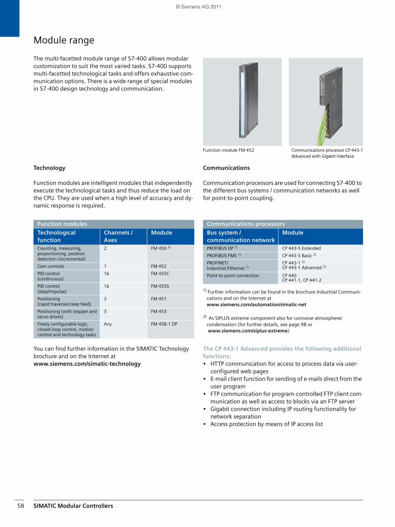
Technology
Function modules are intelligent modules that independently execute the technological tasks and thus reduce the load on the CPU. They are used when a high level of accuracy and dy-namic response is required.
You can find further information in the SIMATIC Technology brochure and on the Internet at www.siemens.com/simatic-technology
Function module FM 452 Communications processor CP 443-1Advanced with Gigabit interface
Communications
Communication processors are used for connecting S7-400 to the different bus systems / communication networks as well for point-to-point coupling.
1) Further information can be found in the brochure Industrial Communi-cations and on the Internet at www.siemens.com/automation/simatic-net
2) As SIPLUS extreme component also for corrosive atmosphere/condensation (for further details, see page 98 or www.siemens.com/siplus-extreme)
The CP 443-1 Advanced provides the following additional functions:• HTTP communication for access to process data via user-
configured web pages• E-mail client function for sending of e-mails direct from the
user program• FTP communication for program-controlled FTP client com-
munication as well as access to blocks via an FTP server• Gigabit connection including IP routing functionality for
network separation• Access protection by means of IP access list
Function modules
Technological function
Channels / Axes
Module
Counting, measuring, proportioning, position detection (incremental)
2 FM 450 2)
Cam controls 1 FM 452
PID control (continuous)
16 FM 455C
PID control (step/impulse)
16 FM 455S
Positioning (rapid traverse/creep feed)
3 FM 451
Positioning (with stepper and servo drives)
3 FM 453
Freely configurable logic, closed-loop control, motion control and technology tasks
Any FM 458-1 DP
Communications processors
Bus system / communication network
Module
PROFIBUS DP 1) CP 443-5 Extended
PROFIBUS FMS 1) CP 443-5 Basic 2)
PROFINET/Industrial Ethernet 1)
CP 443-1 2)
CP 443-1 Advanced 2)
Point-to-point connection CP 440CP 441-1, CP 441-2
SIMATIC_Controller_032011_en.book Seite 58 Montag, 4. April 2011 2:35 14
© Siemens AG 2011

SIMATIC Modular Controllers 59
Point-to-point connection
Point-to-point link via communications processors (CPs) is an extremely powerful and low-cost alternative to bus systems.The advantage of point-to-point links over bus systems is es-pecially pronounced when only a few (RS 485) devices are to be connected to the SIMATIC S7.
The CPs can also easily link third-party systems to the SIMATIC S7. Thanks to the great flexibility of the CPs, different physical transmission media, transmission rates or even cus-tomized transmission protocols can be implemented.
The CPs have a rugged plastic housing with LEDs for displaying operating states and faults.
For each CP there is a configuring package on CD with elec-tronic manual, parameterization screen forms and standard function blocks for communication between the CPU and the CP.
The configuration data are stored in a system block and backed up in the CPU. When modules are replaced, the new module is therefore immediately ready for use.
With the S7-400 point-to-point link modules, adaptation to the physical transmission media is achieved by plugging in the relevant interface submodules, without the need for external converters.
Point-to-point links for SIMATIC S7-400
Scanner Barcode reader
Process controller
SIMOVERT SIMOREG
Modem
PC Printer Robot control
BDE terminal
3rd party PLC G
_ST7
0_X
X_0
0687
SIMATIC S7
Technical data: Point-to-point connection
Application High-speed response with low data volumes
Interconnection
Low-cost:With one variable interface
High-speed:With two variable inter-faces
Transmission rate High (115 200 bit/s) Low (38 400 bit/s) High (115 200 bit/s)
Loadable protocols (Order No. group: 6ES7 340-)
MODBUS Master (-1AA.),MODBUS Slave (-1AB.), Data Highway (-1AE.)
Module CP 440 CP 441-1 CP 441-2
Order No. group: 6ES7 440-1. 441-1. 441-2.
Physical transmission media
RS 232C (V.24) All transmission methods, all interface modules, plug-in, serial20 mA (TTY)
RS 422/485 (X.27) ● (up to 32 nodes)
Integrated transmission protocols
ASCII ●
Printer driver ●
3964 (R) ●
RK 512 ●
SIMATIC_Controller_032011_en.book Seite 59 Montag, 4. April 2011 2:35 14
© Siemens AG 2011

SIMATIC Modular Controllers60
Signal modules
Signal modules are the interface of the controller to the pro-cess. A host of different digital and analog modules provide exactly the inputs/outputs required for each task.
Digital and analog modules differ as regards the number of channels, voltage and current ranges, electrical isolation, diagnostics and alarm functions, etc.
However, the S7-400 signal modules are only a subset of the modules that can be connected to the S7-400 via PROFIBUS DP. Centrally connected signal modules can be con-nected and disconnected during operation. This makes mod-ule replacement extremely easy.
In all the module ranges listed here, SIPLUS extreme compo-nents are also available for corrosive atmosphere/condensation. (For further details, see page 98 or www.siemens.com/siplus-extreme)
Easy installation
The sensors/actuators are connected through front connec-tors. When a module is replaced, the connector is simply plugged into the new module of the same type; the wiring is retained. The coding of the front connector avoids mistakes. The S7-400 is also able to detect whether the front connector is plugged in.
Fast connection
SIMATIC TOP connect makes connection even simpler and faster. Preassembled front connectors with single cores and a complete plug-in modular system comprising a front connec-tor module, connecting cable and terminal block are available.
High packing density
The high number of channels on the modules is a reason for the space-saving design. For example, modules with 8 to 32 digital channels or 8 to 16 analog channels are available.
Simple parameterization
The modules are configured and parameterized using STEP 7, and there are no inconvenient switch settings to be made. The data are stored centrally and, following module replacement, they are automatically transferred to the new module so that no setting errors can occur. No software upgrade is required when using new modules. A configuration can be copied as often as required, e.g. for series machines.
Diagnostics, interrupts
Many modules additionally monitor signal acquisition (diag-nostics) and the signals from the process (process interrupt. e.g. edge evaluation). This makes it possible to react immedi-ately to every process error, e.g. wire break or short circuit, and any process event, e.g. rising or falling edge at a digital in-put. The response of the controller can easily be programmed with STEP 7. On the digital input modules, several interrupts per module are possible.
Parameterization of an analog input module
On the following page you will find criteria for selecting the appropriate signal module for each application.
SIMATIC_Controller_032011_en.book Seite 60 Montag, 4. April 2011 2:35 14
© Siemens AG 2011

SIMATIC Modular Controllers 61
Digital inputs
Digital outputs
1) Available with 32 channels as SIPLUS extreme2) Available as SIPLUS extreme (for further details, see page 98 or
www.siemens.com/siplus-extreme)
Analog inputs
Analog outputs
You can find detailed infor-mation on S7-400 signal modules in the appendix.
Module Voltage range Number of chan-nels
SM 421 1) 24 V DC 16, 32
SM 421 24 ... 60 V UC 16
SM 421 120/230 V UC 16, 32
Module Voltage range
Current range
Number of channels
SM 422 2) 24 V DC 0.5 A 32
SM 422 24 V DC 2 A 16
SM 422 120/230 V AC 2 A 16
SM 422 UC (relay) 5 A 16
Module Measuring range
Resolution Number of channels
SM 431 Power Up to 16 bit 8, 16
SM 431 Current Up to 16 bit 8, 16
SM 431 Resistance Up to 16 bit 4, 8
SM 431 Thermocouples Up to 16 bit 8, 16
SM 431 Resistance thermometer
Up to 16 bit 4, 8
Module Measuring range
Resolution Number of channels
SM 432 2) Voltage, current
13 bit 8
SM 421 signal module
SIMATIC_Controller_032011_en.book Seite 61 Montag, 4. April 2011 2:35 14
© Siemens AG 2011

SIMATIC Modular Controllers62
SIMATIC S7-400H
Hot standby with SIMATIC S7-400H
Synchronization
The method of event-driven synchronization supports fast and bumpless changeover to the redundant CPU in the event of a fault. It resumes processing at the point of interruption with-out any loss of information or interrupts. The operating sys-tem ensures that all commands, which if executed indepen-dently would produce different states in the two systems, operate in synchronism. No programming or parameteriza-tion has to be performed by the user for this purpose.
Features of the SIMATIC S7-400H
DesignThe central devices can be configured in two different ways:When the subunits have to be completely separated from each other for availability reasons, it is appropriate to use two stan-dard racks (UR1 and UR2). Each rack accommodates one CPU and one power supply (PS). If extremely high availability is required, two redundant power supply modules can be used. The distance between the two racks can be up to 10 km. Two CPUs, each with either a single or a redundant power supply, are plugged into the UR2-H rack with a segmented backplane bus. This supports an extremely compact configuration.
Topology of the S7-400H with two controllers and the associated I/O (standard and fault-tolerant)
I/O
Depending on the type of connection, the following I/O com-ponents can be used:• All PROFIBUS slaves for single-sided connection• ET 200M for switched and redundant connection
EngineeringProgramming is possible, as in the case of a standard system, in all STEP 7 programming languages. The programs can easily be ported from standard systems to a redundant system and vice-versa. When the program is loaded, it is automatically distributed onto the two redundant CPUs. The functions and configurations specific to redundancy are parameterized using the S7 H-Systems option package (integrated into STEP 7 Version 5.3 or higher). The planning engineer is free to concentrate solely on controlling the process.
Diagnostics/module replacementApart from the standard diagnostic functions, the following functions are also available:• With the integrated self-diagnostics functions, the system
detects and signals errors before they can affect the pro-cess. They enable the faulty components to be identified and replaced quickly which speeds up repairs.
• All components can be replaced during normal operation (online repair). When a CPU is replaced, all the current programs and data are automatically reloaded. It is also possible to modify the program during normal operation, e.g. changing and reloading of blocks
• Changes can also be made to the configuration during normal operation, e.g. adding or removing DP slaves or modules, changing the memory configuration of the CPU.
The SIMATIC S7-400H is a controller with two H CPUs of the same type; in the event of a fault, changeover takes place from the master system to the standby station. It is suitable for fault-tolerant pro-cesses with hot standby re-quirements (processes with changeover times shorter than 100 ms).
Highlights
■ Performance-oriented solution for time-critical processes
■ Synchronized hardware solution without information loss
■ Many S7-400H components are also available in a SIPLUS extreme version for extreme environmental conditions, e.g. for use where there is a corrosive atmosphere/condensation. For further information, see page 98 or www.siemens.com/siplus-extreme
Highly available communication via Industrial Ethernet
Station BStation A
Station Bassociated I/O
Fault-tolerantE/A
Station Aassociated I/O
Eventsynchronization
S7-400HMaster
S7-400HBackup
G_S
T70_
XX
_006
91
ET 200M
Industrial Ethernet
Fault-tolerant SIMATIC S7-400H with redundant CPUs
SIMATIC_Controller_032011_en.book Seite 62 Montag, 4. April 2011 2:35 14
© Siemens AG 2011

SIMATIC Modular Controllers 63
Fault-tolerant CPUs
Three CPUs are available for the SIMATIC S7-400H to suit different performance requirements.
Apart from high volumes, the H-CPUs are also characterized by high performance.
This is not only visible in a high processing speed, but also in a large communication output. Furthermore, an integrated memory type that detects and automatically corrects memory cells corrupted through external influences is also used. The H-CPUs now also permit a firmware update via the network.
1) One interface can be used either as a PROFIBUS DP or as MPI (Multipoint Interface)2) As SIPLUS extreme component also for corrosive atmosphere/condensation (for further details, see page 98 or www.siemens.com/siplus-extreme)
Sync modules
The three H CPUs are connected by means of fiber-optic cables and "Sync modules" that can be directly plugged into the CPU. This means that no slot in the rack is lost and that communi-cation is extremely fast. The Sync modules can be replaced with the voltage applied.
There are two types of Sync modules:
• For Sync cables up to 10 m in length• For Sync cables up to 10 km in length with the CPUs
414-4H or 417-4H for applications in which the subunits have to be set up at some distance
Technical data: H CPUs
CPU CPU 412-3H 2) CPU 414-4H 2) CPU 417-4H 2)
Dimensions (mm) 50 x 290 x 219
Slots 2
Order No. group: 6ES7 412-3HJ. 414-4HM. 417-4HT.
Work memory
Integrated 768 KB 2.8 MB 30 MB
Instructions 128 K 460 K 5 M
For program 512 KB 1.4 MB 15 MB
For data 256 KB 1.4 MB 15 MB
Processing times
Bit operation 0.075 µs 0.045 µs 0.018 µs
Word operation 0.075 µs 0.045 µs 0.018 µs
Fixed-point operation 0.075 µs 0.045 µs 0.018 µs
Floating-point operation 0.225 µs 0.135 µs 0.054 µs
Bit memories, timers, counters
Bit memory 8 KB 16 KB
S7 timers/counters 2 048 / 2 048
IEC timers/counters ●
Address ranges
I/O 8 KB / 8 KB 16 KB / 16 KB
I/O process image 8 KB / 8 KB 16 KB / 16 KB
Digital channels 65 536 / 65 536 131 072 / 131 072
Analog channels 4 096 / 4 096 8 192 / 8 192
Interfaces
DP 1 1) 2 1)
Sync modules 2
SIMATIC_Controller_032011_en.book Seite 63 Montag, 4. April 2011 2:35 14
© Siemens AG 2011

SIMATIC Modular Controllers64
I/O
I/O interface
The I/O can be connected to suit the availability requirements. The following types of connection are available:
1. Single-sided connection (normal availability) for all PROFIBUS slaves, e.g. ET 200M, ET 200S, ET 200eco
2. Switched connection (increased availability) for ET 200M3. Redundant connection (fault-tolerant) for ET 200M
These configurations can also be mixed.
I/O connection of S7-400H
Y link
With the help of the Y link, a subordinate I/O station with var-ious field devices can be easily connected to a redundant PROFIBUS DP system, e.g. an S7-400H with two DP master systems.
In the event of a fault, the Y link switches over the complete I/O line bumplessly to the active bus channel of the redundant H system.
The Y link supports connection of most types of PROFIBUS slave:
Connection of a lower-level bus system to the S7-400H via the Y link
3
2
1
Rack 1Rack 0
single-channel one-sideddistributed I/O station, e.g. ET 200S
Redundant connection
Switched connection
Single-sided connection
reduntant distributedI/O ET 200M
Redundant pair of modules
DP/PA-Link orY-Link
switched distributed I/O,e.g. ET 200M
single-channel one-sidedI/O modules in central rack
G_S
T70_
XX
_006
92
Drive Other field devices
Lower levelDP master system
RedundantDP master system
Y link
Distributed IO
Y coupler
ET 200S ET 200S
S7-400H
G_S
T70_
XX
_006
93
IM 157
ET 200M
SIMATIC_Controller_032011_en.book Seite 64 Montag, 4. April 2011 2:35 14
© Siemens AG 2011

SIMATIC Modular Controllers 65
Redundant I/O
Principle of redundant I/O
Redundant I/Os are input and output modules that are redun-dantly configured and operated. Maximum availability is of-fered by the implementation of redundant I/O because in this manner, failure of a CPU, a PROFIBUS line and a signal module is compensated for. During normal operation, both modules are active, i.e. in the case of redundant inputs, the values of the shared sensor are read in by two modules, the result is compared and made available to the user as a unified value for further processing.
Principle of redundant I/O
In the case of redundant outputs, the value calculated by the user program is output by both modules.
In the event of a fault, e.g. if one of the two input modules fails, the defective module is no longer addressed, the fault is signaled and processing continues with the intact module only.
Following repair, which may be carried out online, both modules can be addressed again.
Numerous signal modules of the S7-300 (for distributed con-figurations with ET 200M) are available for redundant opera-tion. The prerequisite is STEP 7, Version 5.3 or higher with the option package "S7 H systems" integrated.
Scalable availability
The availability is scalable in accordance with the redundant I/O configuration:
1. Each module in a separate rack with redundant connection to PROFIBUS or
2. Each module in a separate rack with single connection to PROFIBUSor
3. Both modules in one rack
Scalable availability of the redundant I/O
Both inputs are read simultaneously. The right value is automatically selected and processed.
Redundantinput
Master-input
G_S
T70_
XX
_006
94
3
2
1
SC
AL
EA
BL
E A
VA
ILA
BIL
ITY
Redundant input
Master input
Redundant input
Master input
Redundant input
Master input
G_S
T70_
XX
_006
95
SIMATIC_Controller_032011_en.book Seite 65 Montag, 4. April 2011 2:35 14
© Siemens AG 2011

SIMATIC Modular Controllers66
Communications
High availability also applies to communication. Depending on the network topology, redundant connections can be created and activated automatically in the event of a fault.
Fault-tolerant communication is implemented in the S7-400H using double CPs that are connected to the PC using the soft-ware package S7-REDCONNECT.
In the event of a fault, the highly available communication link takes over automatically and invisibly as far as the user is con-cerned. Process industry Traffic tunnel
The bus is safely installed and not at risk of failure. Failure of one component per device will be tolerated.
The same configuration as in Figure 1, but the bus is redundantly configured, i.e. failure of the bus can also be tolerated.
21
Equivalent redundancy circuit diagram:Equivalent redundancy circuit diagram:
Highly-available communication with redundant bus and standard CPs (communication processors)
Highly-available communication with standard bus
G_S
T70_
XX
_006
96
S7-400H S7-400H
Industrial EthernetIndustrial Ethernet
SIMATIC_Controller_032011_en.book Seite 66 Montag, 4. April 2011 2:35 14
© Siemens AG 2011

SIMATIC Modular Controllers 67
Process industry
The same configuration as in Figure 2, but the CPs are also redundantly config-ured. In this case, failure of the bus and one more component per device can be tolerated.
In this configuration, fail-safety of the bus is achieved using the ring structure. Failure of one additional component can also be tolerated.
43
Equivalent redundancy circuit diagram:Equivalent redundancy circuit diagram:
Highly-available communication with ring bus Highly-available communication with redundant busand redundant CPs
Ringbus
G_S
T70_
XX
_006
97
S7-400H S7-400H
Industrial EthernetIndustrial Ethernet
SIMATIC_Controller_032011_en.book Seite 67 Montag, 4. April 2011 2:35 14
© Siemens AG 2011