silicon electrolyte interface stabilization (seista)...1 silicon electrolyte interface stabilization...
TRANSCRIPT
1
Silicon Electrolyte Interface Stabilization (SEISta) Q1 FY19
Anthony Burrell
National Renewable Energy Laboratory
15013 Denver West Parkway
Golden CO 80401
Phone (303) 384-6666
E-mail anthonyburrellnrelgov
Brian Cunningham DOE-EERE-VTO Program Manager
Hybrid Electric Systems Battery RampD
Phone (202) 586-8055
E-mail briancunninghameedoegov
Table of Contents
Page
Overview 1
SEISta Q1 Milestone FY19 4
Project Introduction
This report documents the Silicon Electrolyte Interface Stabilization teamrsquos approach in 1) characterizing the
early-stage silicon-electrolyte interphase (SEI) including progress on identifying the specific reaction pathways
present in the formation of the SEI layer and 2) establishing a procedure for measuring SEI growth rate at
fixed potentials and different cycling regimes
Silicon is a viable alternative to graphitic carbon as an electrode in lithium-ion cells and can theoretically store
gt3500 mAhg However lifetime problems have been observed that severely limit its use in practical systems
The major issues appear to involve the stability of the electrolyte and the uncertainty associated with the
formation of a stable SEI at the electrode Recently calendar-life studies have indicated that the SEI may not
be stable even under conditions where the cell is supposedly static Clearly a more foundational understanding
of the nature of the siliconelectrolyte interface is required if we are to solve these complex stability issues A
new multi-lab consortium has been formed to address a critical barrier in implementing a new class of
materials used in lithium-ion batteries that will allow for smaller cheaper and better performing batteries for
electric-drive vehicles This consortium named the Silicon Electrolyte Interface Stabilization (SEISta) project
was formed to focus on overcoming the barrier to using such anode materials Five national laboratories are
involved the National Renewable Energy Laboratory (NREL) Argonne National Laboratory (ANL)
Lawrence Berkeley National Laboratory (LBNL) Oak Ridge National Laboratory (ORNL) and Sandia
National Laboratories (SNL)
The SEISta project was specifically developed to tackle the foundational understanding of the formation and
evolution of the solid-electrolyte interphase on silicon This project will have as its primary goal an
understanding of the reactivity of the silicon and lithiated silicon interface with the electrolyte in lithium-ion
systems It consists of researchers from multiple national laboratories (NREL ANL LBNL ORNL and SNL)
2
working toward clear unified goals The Silicon Deep-Dive team which focuses on the science and technology
barriers in functional electrodes is a critical partner in this work Many of the researchers are shared between
both teams and we hold joint meetings to ensure effective communication between the teams
The current goals of SEISta are
Quarter 1 Milestone Have determined if the pristine surface of the silicon influences the composition and the
function of the SEI after 1 10 and 50 cycles (XPS SIMS IR and Raman STEM SSRM)
Quarter 2 Milestone Have determine that the nature of the silicon surface can affect the composition function
and the thickness of the SEI
Quarter 3 Milestone Have determine how water concentration (as a function of water content up to 100 ppm)
in the electrolyte affects SEI thickness and composition (electrochemistry spectroscopy impedance) of the
SEI formed at 15 10 07 04 015 and 005V vs LiLi+rdquo
Quarter 4 Milestones Have determine the nature of the soluble SEI components that are formed over 10
cycles that are soluble in the gen 2 electrolyte
Approach
The SEISta team works to ensure that protocols for sample preparation experimental design and
implementation as well as data reporting are consistent across the whole team Each laboratory is working
toward the same set of quarterly milestones using its own specific talents and capabilities in a concerted effort
with the other team members This joint focus results in multiple researchers interacting to produce and
analyze data to ensure that individual experimental variations will not lead to erroneous results Critical to the
success of this effort is the use of standard samples that can be shared by all parties In addition to weekly
whole-team video presentations we have held on-site face-to-face meetings each quarter for all team members
and other interested parties to brainstorm and sort out issues with existing experiments and jointly develop new
experimental plans
Objectives
The critical issues that SEISta is attempting to determine are
bull What are the properties of the lithiated siliconelectrolyte interface
bull What is the silicon SEI actually made of and what reactions are contributing to it
bull How fast does the silicon SEI grow
bull Does it stop growing
bull Is it soluble
bull Can it be stabilized
For FY19 the team continues to focus on three broad tasks
Materials Standardization ndash This task is critical to the development and deployment of standardized samples
and experimental procedures across the team We will continue to provide full characterization to any new
sample that is to be used for SEI studies to ensure reproducibility and full understanding of the material This
quarterrsquos work focused on developing new oxide coatings and methods to control the thickness and density of
oxide samples In addition work on the silicon nanoparticles has made progress with the enhancement of the
3
materials collection and handling system in the plasma reactor Although this work dominated the early part of
the project and is still critical to its success it is now only a minor part of the work and this is reflected in the
relative balance of this quarterly report
Model Materials Development and Characterization ndash The nature of the electrode-electrolyte interaction in
silicon electrodes is at the heart of the formation and stability of the SEI The inherent chemical reactivity of
silicon with common electrolytes has been a focus for this team and will be a primary focus moving to quarter
2 The synthesis of well-defined silicon nanoparticles and the different chemical markups of lithiated silicon
surfaces is being probed by preparing model compounds and thin films that maycan exist in silicon anodes
Lithium silicides silicates and other inorganic material (LiF Li2O) are being prepared and their reactivity
with electrolytes is being determined These materials also act as standard spectroscopy samples for the
researchers who are looking at the formation of the SEI on different silicon materials
SEI Characterization ndash The overall objective for SEISta is to understand the nature and evolution of the SEI
on silicon anodes The materials standardization and model compounds will enable the researchers to
systematically investigate the formation of the solid-electrode interphase using a wide variety of the
spectroscopy techniquesmdashfrom different optical microscopy and electrochemistrymdashto determine how the
SEI forms based on the nature of the silicon surface and how it evolves over time This section of work will
continue to grow in scope as we move beyond the sample-characterization phase of the project and toward
understanding the nature and evolution of the SEI This part of the project now represents the bulk of the work
and as such this quarterly report is largely reporting on work leading to this outcome
4
SEISta Milestones FY18 Silicon Electrolyte Interface Stabilization (SEISta)
SEISta Team
Background
The overall objective of the SEISta project is to better understand the formation and evolution of the solid-
electrolyte interphase (SEI) on silicon anodes Silicon is a viable alternative to graphitic carbon as an electrode
in lithium-ion cells and can theoretically store gt3500 mAhg However lifetime problems have been observed
that severely limit its use in practical systems The major issues appear to involve the stability of the electrolyte
and the uncertainty associated with the formation of a stable SEI at the electrode Recently calendar-life
studies have indicated that the SEI may not be stable even under conditions where the cell is supposedly static
Clearly a more foundational understanding of the nature of the siliconelectrolyte interface is required if we
are to solve these complex stability issues A multi-lab consortium has been formed to address a critical barrier
in implementing a new class of materials used in lithium-ion batteries that will allow for smaller cheaper and
better performing batteries for electric-drive vehicles This consortiummdashthe Silicon Electrolyte Interface
Stabilization (SEISta) projectmdashwas formed to focus on overcoming the barrier to using such anode materials
Five national laboratories led by the National Renewable Energy Laboratory (NREL) are involved NREL
as well as Argonne (ANL) Lawrence Berkeley (LBNL) Oak Ridge (ORNL) and Sandia National
Laboratories (SNL)
Quarter 1 Milestone
Have determined if the pristine surface of the silicon influences the composition and the function of the SEI
after 1 10 and 50 cycles (XPS SIMS IR and Raman STEM SSRM)
Results
For FY18 all milestones are 100 complete Most of the following report details the work that enables the
completion of this milestone Specific finding from this work are that the non-passivating behavior of silicon
thin films has been directly observed for the first time as an independent effect from the cracking of silicon
particles due to the lithiation In addition dense thermal oxides of 5 nm or more severely impede lithiation
whereas 1 nm SiO2 allows lithiation to proceed unimpeded However SEIs formed on native SiOx on Si were
thicker as determined by XPS and SSRM XPS results showed that SEI formed on native SiOx showed greater
C Li and F content Clearly the nature of the silicon surface is major factor in the stabilization of the SEI
We will explore this more in the coming months
5
Examination of the Passivating Nature of the Silicon Electrolyte Interface (SEISta)
[LBNL]
Joint report LBNL (I Hasa L Zhang P Ross R Kostecki) and ORNL (G Yang G Veith)
Background
The primary objective of our effort is to clarify and understand the processes occurring at the
siliconelectrolyte interface The reductive decomposition of the electrolyte in lithium-ion systems employing
silicon anodes is inevitable since the working potential of the electrode is far below the electrochemical
stability window of the electrolyte components In principle the insoluble decomposition products
precipitating on the electrode surface result into the formation of a passivating surface film which suppress
further electrolyte decomposition[12] However the inherent instability of the siliconelectrolyte interface
strongly inhibits the surface passivation which is further endangered by the mechanical instability of the
electrodes which upon alloying with lithium experience a huge volume expansion responsible of active
material cracking and consequent instability of the passivating film[3] A better understanding of the kinetic
processes occurring upon cycling will enable an efficient implementation of silicon based electrodes in high
performance lithium-ion batteries To accomplish this we address the inherent non-passivating behavior of
silicon model electrodes in organic electrolytes In particular this last quarter we have been focused on the
ldquoCorrosion Taskrdquo of the SEISta project which is a coordinated research thrust aiming at the understanding and
the evaluation of the non-passivating behavior of silicon anodes The overall goal of this effort is to provide a
basic understanding and ways of effective mitigation of Si anode corrosion in organic carbonate-based
electrolytes Oak Ridge National Laboratory fabricated all the model electrodes for the Corrosion task while
the team at Berkeley Lab electrochemically investigated the corrosion currents involved upon cycling
Results
The evaluation of the passivating properties of silicon anodes involved the definition of the electrochemical
protocols to be employed for the determination of the corrosion currents Two different electrochemical
protocols have been established involving galvanostatic tests followed by chronoamperometry measurements
both in potentiostatic mode at fixed voltage values (Protocol 1) and at open circuit voltage conditions
(Protocol 2) A schematic of the electrochemical cell and a description of the two protocols is given in Fig1
Figure 1 Schematic representation of the electrochemical cell set up cell components and protocols employed in
the Corrosion Task
6
Following the definition of the protocols a screening study of the most suitable model electrodes has been
performed The selection criteria for the determination of the best model electrodes involved the quantification
of the residual currents (corrosion currents) upon cycling A fundamental requirement for the substrates is that
lithiation should occur exclusively at the expense of the amorphous silicon thin film deposited on the
substrates so that the latter ones should result inert toward lithiation and should present a very smooth and
defined surface for the deposition of amorphous silicon
Figure 2 shows representative images of some of the electrode prepared for this work We chose copper based
current collectors due to its stability against lithium metal The choice of electrode materials can be divided
into two classes of electrodes (1) copper encapsulated substrates and (2) pure metal rods The encapsulated
substrates were prepared by sectioning silicon or sapphire wafers These wafers coated on the ldquoroughrdquo side by
physical vapor deposition from a high purity copper target A 20 m film was deposited on the substrate back
and rained down along the sides The substrate was flipped and an additional 2 m of Cu was deposited on the
ldquosmoothrdquo side of the substrate Electrical continuity was measured on each substrate to estimate if copper
coated the entire substrate A portion of the copper coated substrates were loaded on a substrate holder and a
silicon film was deposited on the ldquosmoothrdquo side of the substrate (Fig 2- Right)
The second set of samples were prepared using high purity oxygen-free high thermal conductivity (OFHC)
copper 3rdquo rods of copper along with 2 mm disks of cupper were cut from OFHC rod stock The diameter of
the rod was set to fit the Swagelok cells used for the corrosion current tests The cut rods and disks were
polished with progressively finer grits (down to 03 m) until a mirror like finish was obtained Fig 2 ndash
Middle The rods were cleaned in hexane to remove oils and a dilute citric acid solution to remove residual
oxide and polar molecules Some rods were coated with PVD shrink wrap (McMaster Carr) to attempt to
further isolate the sides of the rods from electrochemical reactions 50 nm amorphous silicon films were
deposited on the polished copper rods using the same chamber and deposition conditions Fig 2 - Left The
sides of the rods were masked with Kapton tape to produce a well-defined electrode area
Figure 2 Left ndash Images of copper rods before silicon deposition Middle ndash image of polished copper rod surface Right ndash
Picture of as grown silicon films on copper coated sapphire
7
Figure 3 shows schematic cross sections of the electrodes (top) along with representative cyclic voltammetry
data collected for the bare and silicon coated substrates These encapsulated model electrodes exhibited large
currents and allowed partial lithatiation As a result these samples were discontinued due to lithiation of the
substarate underneath the copper film The copper piston was identified as the best substrate due to its
(expected) inactivity toward lithium
The developed Protocol 1 (GCPL +CA) has been applied to the selected model electrode and the residual
currents after every lithiation have been calculated and reported in Fig 4
Fig 4 shows that the residual
background current value observed after
the 1st cycle is about 27 microA cm-2 for the
bare copper piston while by adding
silicon the residual current is about 61
microA cm-2 The results indicate that almost one third of the current values observed is associated to the copper
Figure 4 Application of Protocol 1 (GCPL +CA)
to the bare copper substrate (a b) and to the
silicon added model electrode (c d) Fig (a)
and (c) show the first galvanostatic cycle at
50 microA cm-2 and the second lithiation followed
by a potentiostatic voltage step for 24 hours
at 005 V The test has been applied for three
cycles The current change during the 24
hours has been monitored and plotted as
overlapping I vs t curves in Fig (b) and (d)
Tests performed at room temperature using
Gen 2 electrolyte (12 M LiPF6 in ECEMC 37
wt)
Figure 3 Schematic of the three model electrodes investigated to evaluate the inactivity of the substrates Comparative
cyclic voltammetry tests (1st cycle shown) for the bare substrates and the substrates with the sputtered amorphous
silicon Tests performed at room temperature using Gen 2 electrolyte (12 M LiPF6 in ECEMC 37 wt)
8
piston The current values involved with the bare Cu substrate are very large and most likely related to the
large surface area of copper exposed to the electrolyte in T-cell configuration In order to find a more suitable
substrate involving less exposed surface area different copper substrates have been tested A schematic
representation of the investigated substrates and the residual current values observed after the 1st cycle by
appling Protocol 1 are reported in Table 1
Copper foil (12 mm diameter) presented the smaller residual current values Accordingly the first model
electrode of choice for the evaluation of the corrosion currents has been identified as 500 nm amorphous
silicon (with 3 nm native oxide) deposited on copper foil (500 nm Si + 3 nm SiO2 on Cu) The 500 nm Si thin
film has been investigated in four electrolyte solutions ie 12 M LiPF6 ECEMC (37 wt) 12 M LiPF6
ECEMC (37 wt) + 10wt FEC 12 M LiTFSI ECEMC (37 wt) and 12 M LiTFSI ECEMC (37
wt) + 10wt FEC The electrochemical characterization has been performed both in terms of cyclic
voltammetry and galvanostatic cycling test as reported in Fig 5
Interestingly the inset of Fig 4 reports the current values involved during the electrolyte decomposition
process occurring before lithiation The LiPF6 based electrolyte presents the largest reductive current density
while the presence of FEC and the substitution of LiPF6 with LiTFSI strongly reduce the current involved in
the process The observation has been confirmed by galvanostatic cycling test as reported in Fig 4 (b) Indeed
the first Coulombic efficiency has been calculated to be 814 843 865 and 758 respectively for the
12 M LiPF6 ECEMC (37 wt) 12 M LiPF6 ECEMC (37 wt) + 10 FEC 12 M LiTFSI ECEMC (37
wt) a0nd 12 M LiTFSI ECEMC (37 wt) + 10 FEC electrolyte solutions Protocol 1 (GCPL + CA) has
been applied to the above-mentioned system in order to understand and evaluate the effect of different salts
Table 1 Copper based substrates investigated with Protocol 1 The values of the residual current observed after 24 hours
of potentiostatic step at 005 V are reported The thin copper foil presents the lower values of the order of 1 microA cm-2
Figure 5 (a) First lithiation ndashde-lithiation process of 500 nm Si thin film on Cu foil observed by cyclic voltammetry by using
four different electrolyte solutions A scan rate of 01 mV sec-1 has been applied within the 005 V ndash 15 V potential range
Inset shows the enlarged potential region of the electrolyte decomposition (b) Galvanostatic cycling test of the same
systems performed at 50 microA cm-2
9
(LiPF6 vs LiTFSI) and the effect of the additive addition (10 wt FEC) on the passivating properties of
silicon
Fig 6 reports the galvanostatic cycling test (with associated potentiostatic steps) and the I vs t curves obtained
during the constant voltage step at 005 V for the 500 nm Si thin film in three different electrolytes
It is interestingly shown that the residual current detected after 24 hours at 005 V are very large for the 12 M
LiPF6 ECEMC (37 wt) electrolyte while by substituting LiPF6 with LiTFSI the current value is about 7
times smaller The same effect is observed with the addition of 10 FEC to the bare 12 M LiPF6 ECEMC
(37 wt) solution The data are in agreement with the CV and GCPL tests reported in Fig5 It is also
observed that the passivation of silicon improves upon cycling as demonstrated by the lower current values
observed after the third potentiostatic step when compared to the first one
The same kind of analysis has been conducted to investigate also other effects on the corrosion currents and
passivating properties of silicon The investigated effects include the state of charge at which the
potentiostatic step is applied (05 V vs 005 V) the effect of the silicon thickness (500 nm Si vs 50 nm Si -
cracking effect of silicon upon cycling-) and the effect of the surface silicon oxide layer on silicon which has
also been investigated by applying protocol 2 (GCPL +OCV) (3 nm native SiO2 vs 10 nm sputtered SiO2)
All the investigated effects and related preliminary conclusions are summarized below in Table 2
Figure 6 Application of Protocol 1 (GCPL +CA) to the 500 nm Si thin film model electrode by using (a b) 12 M LiPF6
ECEMC (37 wt) (c d) 12 M LiPF6 ECEMC (37 wt) + 10 FEC and (e f) 12 M LiTFSI ECEMC (37 wt) (a b
c) show the galvanostatic cycling with associated potentiostatic step at 005 V (b d f) reports the related current
density measurement during the potentiostatic step
10
Conclusions
The corrosion task has led to the definition of standard protocols enabling a relative quantification of the non-
passivating behavior of silicon model electrodes A set of electrodes has been investigated to define the model
electrodes of choice Silicon thin films have been identified as the best model electrodes so far investigated By
applying Protocol 1 and 2 to various systems characterized by different properties (thickness of silicon
thickness of the oxide surface layer) and also different interfaces (employment of four types of electrolyte
solutions) preliminary conclusions have been obtained
In summary the non-passivating behavior of silicon thin films has been directly observed for the first time as
an independent effect from the cracking of silicon particles due to the lithiation A visualization of the
improvement of the passivation properties upon cycling has been quantified suggesting a thickening of the
passivating film on the silicon surface The beneficial effect of FEC for the SEI stability has been confirmed
and the use of LiTFSI as alternative salt to improve the SEI stability is proposed According to our
preliminary results the silicon oxide layer has a detrimental effect on the passivating properties of silicon
electrodes Further studies in this regard are still required
References
[1] E Peled J Electrochem Soc 126 2047-2051 (1979)
[2] M Winter Zeitschrift Fuumlr Phys Chemie 223 1395-1406 (2009)
[3] MN Obrovac VL Chevrier Chem Rev 114 11444-11502 (2014)
INVESTIGATED EFFECTS CONCLUSION
Effect of the salt LiPF6 vs LiTFSI LiTFSI based electrolytes exhibit lower residual currents
Effect of additives 10 wt FEC addition FEC improves the passivation properties of Si
Effect of the state of charge on corrosion
current 05 V vs 005 V
Larger currents are observed at 005 V than 05 V
Effect of Silicon thickness 500 nm vs 50 nm
Si
decoupling cracking effect from catalytic
activity of Si
The cracking effect is responsible of about 60 of the
parasitic currents observed in fully lithiated state
Effect of SiO2 on passivating behavior SiO2 inhibits passivation of silicon surface
Table 2 Summary of the investigated effects on the passivating properties of silicon and preliminary
conclusions
11
Nature of the Silicon Surface with Cycles ndash in-situ Spectroscopic Analysis (NREL)
Sang-Don Han and Bertrand Tremolet de Villers (NREL)
Background
Due to complexity high reactivity and continuous evolution of a silicon-electrolyte interphase (SiEI) it
remains a poorly understood topic in advanced Li-ion battery research and its detailed and real-time analysis is
a great challenge Vibrational spectroscopy is one of the most important avenues for understanding and
quantifying the interfacial chemical and electrochemical reactions Raman and Infrared (IR) spectroscopy are
attractive due to their versatility and they are used extensively by the battery community in their ex-situ form
Developing in-situ methods of these techniques however will provide new insight and help in elucidating the
mechanism of interfacial failure in battery systems Moreover combining in-situ analysis from both Raman
and IR spectroscopy will provide detailed and complementary information Raman spectroscopy relies on
polarizing the electron cloud associated with a chemical bond rather than measuring the associated dipole
moment (as in IR spectroscopy) Therefore the combination of these two techniques in one study enables
analysis that may otherwise be missed by applying only a single technique This study can provide a guidance
to stabilize SiEI by understanding of the underlying chemistry and physics and providing mechanical
explanation of surface chemistry and various reactionsinteractions within the SiEI
Results
The demonstrated experiment has the unique ability to link the causal nature of the electrochemical response
with both the changing solution structure of the electrolyte and the evolving SiEI In doing so it can provide a
mechanistic insight into the origins of deleterious performance in Si anode systems This work aims to remedy
the void in understanding how reduction of electrolyte (upon discharge) and (de)insertion of Li+ ions into Si
anode (upon dischargecharge) effects Si anode-electrolyte interface Specifically the Raman analysis can be
paired with electrochemical analytical techniquesmdashsuch as cyclic voltammetry and chronopotentiometry
chronopotentiometrymdashto determine which solution structures andor aspects of the electrolyte decompose at
specific voltages and cycles and how these changes influence on Si anode-electrolyte interphase This analysis
will help inform the rational design of next generation electrolyte systems including additives designed for Si-
based advanced battery systems
In-situ Raman Cell and Instrumentation Details Based on extensive literature and internet survey an in-situ
Raman cell (Fig 1 ECC-Opto-Std) was purchased from EL-CELL GmbH to investigate the electrode-
electrolyte interface before during and after electrochemical operation1 Among four different cell
configurations (eg 2-electrode sandwich 2-electrode side-by-side 3-electrode side-by-side and standard
sandwich) 2-electrode side-by-side setup (left picture of Fig 1) was selected to enable focusing electrode-
electrolyte interface during cycling The cell is expected to measure solution structure and chemical
composition and to analyze (electro) chemical reactivity and evolution
Figure 1 in-situ cell with side-by-side setup for spectroscopic analysis
12
We are using a Renishaw inVia confocal Raman microscope with three available laser light excitation choices
532 nm 633 nm and 785 nm So far we have only used the 532 nm source as it seems to provide the best
signal from our samples with minimal fluorescence background The 50x metallurgic microscope lens (09
NA) combines good confocality and light collection The sapphire (Al2O3) window of the in-situ cell holder is
thin enough (300 microm) to allow a focal spot on the silicon wafer and electrolyte below the window
Initial measurements and peak assignments Fig 2 shows a typical Raman spectrum collected through an in-
situ cell holder We have invested time to build a reference table for peak assignments (Table 1) and continue
to refine it Fig 3 shows the Raman spectra for both electrolyte systems Gen2 electrolyte vs Gen2 with 10
wt FEC electrolyte Based on a comparison of the two electrolyte systems Raman shift of FEC (eg 728
868 and 908 cm-1) can be assigned as shown in Table 1
Figure 2 Representative Raman spectrum with an in-situ cell Observed peaks were assigned to the sapphire window
(381 417 748 cm-1) a strong signal from the crystalline silicon wafer anode (520 cm-1) and many peaks assigned to
the various components of a standard Gen2 electrolyte (12M LiPF6 in 37 ECEMC)
Figure 3 Comparison of Raman spectra of Gen2 electrolyte (red) and Gen2 with 10 wt FEC additive (black)
13
Table-1 Raman peak assignments
Raman Band Center (cm-1) Assignment Species of Origin Reference(s)
380 Eg Al2O3 1
417 A1g Al2O3 1
431 Eg Al2O3 1
450 Eg Al2O3 1
480 a-Si
513
520 1TO c-Si
530
578 Eg Al2O3 1
645 A1g Al2O3 1
720 ο O-C-O EC 2
728 ο O-C-O FEC 2
733 ο O-C-O EC⋯Li+ 2
740 υ P-F PF6- 2
742 υ P-F PF6-⋯Li+ 2
748 Eg Al2O3 1
868 υ C-F FEC 2
897 β C-C EC 2
908 β C-C FEC 2
932 δ O-C-O EMC 3 this work
945 δ O-C-O EMC⋯Li+ 3 this work
1488 δ CH3 EC 2
1705-1730 υ C=O EMC⋯Li+ this work
1748 υ C=O EMC this work
1778 υ C=O EC 2
1804 υ C=O EC 2
References (1) DOI1010631367972 (2) DOI101021acsnano8b05038 (3) DOI101039C6CP07215A
Preliminary in-situ Raman Measurements upon Cycling For in-situ Raman measurement a crystalline silicon
wafer (c-Si 525 microm lt0005 Ω cm p-type) strip and a lithium metal foil were used as the working and the
counterreference electrodes respectively (Fig 1) Raman spectra was collected at various voltagestimes
during galvanostatic cycling (at 5 microA) of the in-situ cell The OCV of assembled cell was at around 285 V vs
LiLi+ (hereafter) which is usually observed from coin-type cell cycling tests (Fig 4) Upon the 1st discharge
(285 - 011 V) electrolyte decomposition and initial SiEI formation were observed at between ~13 and 011 V
(left side of red-dotted line) Then lithiation of c-Si (c-Si + xLi rarr a-LixSi) was observed at around 0115 V
for 14 hrs as programmed Upon the 1st charge (011 - 150 V) low-voltage and high-voltage delithiation
plateaus of amorphous Si were observed as shown in previous study2 a-Li(x+x)Si rarr a-LixSi + xLi and a-
LixSi rarr a-Si + xLi In the case of Raman spectra during discharging and charging we observed a reduction
of the crystalline silicon peak at 520 cm-1 and an increase in a broad feature that may be amorphous silicon
(broad centered ~480 cm-1) as shown in Fig 4 (inset)
14
Problems encountered and mitigating strategies We are still exploring optimal measurement parameters such
as light excitation intensity collection time spectra averaging and objective height because of weak SN
ratios for some important electrolyte component scattering bands eg EMC coordinated with Li+ in the region
of 1700 - 1740 cm-1 To increase our signals we are trying different combinations of light excitation intensity
(1- 50 mW) collection time (2 - 300 sec) and spectra averaging (3 - 50 accumulations) Increasing the
excitation intensity certainly increases the SN ratio but can easily damage the samples Fig 5 shows Raman
spectra collected at the same spot at 50 mW 532 nm laser excitation Initially we have good SN but after 20
collected spectra we see that we have lost most of our signal Subsequently we have lowered the excitation
intensity and increased the collection time from 10 sec to 300 sec If we have to wait 5 mins for one spectrum
we may miss some of the dynamics happening during the cell electrochemical cycling
In addition we are struggling to find an appropriate spot for SiEI study (right above the Si wafer vs side of the
Si wafer) because of inhomogeneous distribution of SiEI in an overall Si wafer strip which is possibly due to
heterogeneous structure of each material and consequences lack of electrolyte (and limited Li+ ion
Figure 4 Galvanostatic cycling of the in-situ Raman cell and Raman spectra collected during the first cycle (inset)
Figure 5 Galvanostatic cycling of the in-situ Raman cell and Raman spectra collected during the first cycle (inset)
15
conductivity) Therefore wersquore designing a different shape of Si wafer to obtain relatively homogeneous
distribution of SiEI which can facilitate in-situ Raman measurements
Conclusions
Based on extensive literature survey and several initial Raman measurements we built a reference table for
peak assignments of standard Gen2 electrolyte components (eg EC EMC PF6-) additive (FEC) and an in-
situ cell part (eg Al2O3) which continues to refine Utilizing a well-designed in-situ cell a reasonable and
meaningful electrochemical performance data was obtained with initial promising Raman data Wersquoll address
the issues that we encountered during preliminary in-situ Raman measurements by exploring optimal
measurement parameters designing a different shape of Si wafer and finding an appropriate Raman
measurement spot
References
1 httpsel-cellcom
2 M N Obrovac and L J Krause J Electrochem Soc 2007 154 A103-A108
Electrochemical Testing of Silicon Wafer Anodes With SiO2 Coatings (NREL)
Manuel Schnabel (NREL) Steve Robbins (NREL) Chunmei Ban (NREL) Paul Stradins (NREL)
Background
Polished silicon wafers provide the most controlled silicon material with which to study the fundamental
processes occurring during the lithiation of silicon from an electrolyte In addition they can be oxidized
resulting in dense SiO2 layers of varying thickness whose effect on lithiation and battery electrochemistry can
be studied as a model system for ndash typically oxidized ndash Si powders that would be used in commercially
relevant batteries In the following we describe results obtained on Si wafer anodes with 1-30 nm SiO2
coatings The coatings were prepared by thinning 100 nm thermally grown SiO2 on Si down to the desired
thickness using a buffered HF etching process developed in FY18
Results
1 O-ring Cells for Accurate Electrochemical Characterization ndash Achieving reproducibility
As reported in FY18 Si wafers with SiO2 coatings must be tested in cells that define the electrochemically
active area of the wafer using an O-ring in order to avoid participation of the wafer edges or rear in the
electrochemical processes This is crucial because the edges in particular are not coated with SiO2 and are thus
initially much more electronically conductive
However a cell with an O-ring necessarily utilizes a larger electrolyte volume and we found that this can lead
to more pronounced side reactions When only cleaning cell parts in dimethyl carbonate between experiments
galvanostatic cycling at 20microAcm-2 yields continuous electrolyte reduction at voltages far above the lithiation
potential Through a series of experiments it was found that using fresh Li metal for reference and counter
electrodes using fresh electrolyte and cleaning cell parts in organic solvents as well as water between
experiments was crucial to suppress electrolyte reduction With this procedure we are able to achieve
lithiation at current densities down to 5microAcm-2 Unfortunately current densities of 20 and 07microAcm-2 do not
allow lithiation even with this optimized procedure (see Fig 1) This result agrees with one reported by LBL
earlier suggesting that this effect is not related to our particular cell components but perhaps to the fact that
~14mL electrolyte is used per cm2 of anode area as opposed to ~20microLcm-2 in a typical coin cell
16
Figure 1 Galvanostatic cycling results obtained with an O-ring cell and Si wafer anode as a function of current density at NREL
(4h half-cycles for 5 and 2microAcm-2 12h for 07microAcm-2) Right comparable results reported by LBL for a single lithiation cycle
2 Effect of SiO2 thickness on lithiation
Utilizing these O-ring cells we proceeded to study the effect of 1-30 nm thermal SiO2 coatings on the
lithiation of Si wafers Galvanostatic cycling at 20 microAcm-2 in Gen2 electrolyte indicates that while Si with 1
nm SiO2 will lithiate above 0 V vs Li Si with 3 nm SiO2 will only lithiate after a potential spike to -04V vs Li
Thereafter it actually cycles with higher Coulombic efficiency (CE) than Si with 1 nm SiO2 However Si with
5-30 nm SiO2 initially require voltages below -10V vs Li to sustain 20 microAcm-2 resulting in localized Li
plating at pinholes in the SiO2 rather than lithiation The latter is confirmed by visual inspection of the
electrodes after cycling and is also evident from the Coulombic efficiencies which exceed 98 after the first
cycle for 1 and 3 nm SiO2 but vary wildly between 40 and 85 for 5nm or more of SiO2 (see Fig 2)
Figure 2 Photographs of Si wafers with 3 nm (left) and 5 nm (middle) after galvanostatic cycling at 20microAcm-2 without lower
potential cutoff The former lithiates in area defined by O-ring whereas latter does not lithiated and undergoes Li plating and
stripping at pinholes Right Coulombic efficiency (CE) of galvanostatic cycling for different SiO2 thicknesses 3 nm SiO2 yields
higher CE than 1 nm SiO2 5 nm SiO2 and above have terrible CE as only Li pinhole plating and stripping occurs
17
Figure 3 Cyclic voltammetry curves (left_ 1st cycle right 4th cycle) obtained on Si wafers with 1-5 nm SiO2 Inset peak currents
as a function of SiO2 thickness
To understand these phenomena in more detail cyclic voltammetry (CV) was performed on Si with 1-5 nm
SiO2 (see Fig 3) Lithiation only occurred in the 10 nm sample in the first cycle but by the fourth cycle
lithiation occurred in samples with up to 29 nm SiO2 Samples with 39 nm and 46 nm SiO2 on the other hand
exhibit no lithiation or reversible electrochemistry during ten CV cycles Two distinct delithiation peaks are
observed for 10 and 14 nm SiO2 but only the higher-voltage peak is observed for the 29 nm SiO2 suggesting
a unique delithiation chemistry that may be correlated to the high CE during galvanostatic cycling The peak
currents (005mV for lithiation 05V for delithiation) decrease exponentially with SiO2 thickness indicating
that tunneling electron transfer across the SiO2 may play a key role in the reaction kinetics
Conclusions
We have developed a way to reliably cycle coated Si wafers in a manner free from edge effects at current
densities down to 5microAcm-2 Applying this technique to studying Si coated with 1-30 nm thermal SiO2 we find
that dense thermal oxides of 5 nm or more severely impede lithiation whereas 1 nm SiO2 allows lithiation to
proceed unimpeded Intermediate thicknesses of ~3 nm alter the delithiation chemistry while yielding
improved CE during galvanostatic cycling The thickness dependence of peak currents in CV suggests an
effect of tunneling through the SiO2 on reaction kinetics
18
The Nature of the Li ndash SiO2 layer on the Silicon Electrolyte Interface (SEISta)
Silicon Electrolyte Interface Stabilization (SEISta)
Jaclyn Coyle (UC Boulder) Kevin Zavadil (SNL) Kyle Fenton Josey McBrayer Chris Apblett (SNL)
Background
This quarter we have focused on characterizing the electrochemical response both through cyclic
voltammetry and through constant current chargedischarge characterization of the silicon samples coated with
silicates containing varying amounts of Li in the SiOx layer These studies were performed using a standard
Gen-2 electrolyte without FEC We also performed electrochemical impedance spectroscopy on samples
exposed to the Gen-2 electrolyte continually and collected EIS spectra as a function of time and temperature
Results
LixSiyO CV Studies
Standard samples of thin film Si (50nm Si500nm Cu650um C-Si degenerate100nm Ti500nm Au) were
prepared and diced using the methods previously described These samples were then used as substrates for
the sputter deposition of 40nm thick lithium silicates of varying compositions (SiO2 Li2Si2O5 Li2SiO3 and
Li3SiOx) expected from the tie line on the Li-Si-O ternary for lithiation of SiO2 These correspond to a 0 11
21 and 31 composition of LiSi Samples were then assembled into half cells using Li metal as a
counterelectrode in a standard coin cell configuration using gen-2 electrolyte (ECDMC 37 12M LiPF6)
without FEC Cyclic voltammetry was conducted at 10uVsec sweeps from open circuit to 008V What was
observed was that in the absence of pre-existing lithium within the oxide the onset potential for lithiation was
observed at 023V in good agreement with other observations for SiO2 coated Si samples However if lithium
was present at all in the oxide the onset potential was significantly higher near 035V and there were plateaus
or peaks that manifested in the lithiation sweep A first plateau that is present for all lithium containing
silicates exists at 031V vs LiLi+ which does not exist for the pure SiO2 film There are additional
plateauspeaks at lower potential with increasing lithium content in the oxide resulting in an increasing onset
potential for the second plateau It may be that the first plateau is based upon the formation of Li12Si7 with Li
inserting into the Si substrate directly from the glass and the lower potential plateaus onsetting at the
formation of Li14Si6 and Li13Si4 respectively as the amount of available lithium for insertion from the oxide
increases These first cycle CV curves are shown in Figure 1
Further cycling of the samples in CV result in a steady evolution of both the early onset potential plateau and
the lower potential insertions At the second cycle (see figure 2) SiO2 now shows some of the peaks observed
from the silicates at both the Li12Si7 and Li14Si6 state and by the 14th cycle the SiO2 is closely matched to
those films with the starting silicates which potentially match to the onset of the Li14Si6 phase This suggests
that upon cycling any native starting oxide is lithiated to behave electrochemically similarly to those oxides
that start with lithium in them suggesting that evolution of the silicon oxide film towards a silicate like
structure may be happening However evidence of the silicates through direct beam observation are unable to
identify these silicates directly suggesting that it may just be the existence of lithium within the film that gives
rise to these effects rather than for formation of the stoichiometric silicates in the SiO2 network
19
Figure 2 CV of 50nm thick SixLiyO films under slow CV Conditions 25C 10uVsec 50nmSi 500nmCu 300umSi
20nmTi 200nmAu WE Li CE Li RE
Figure 3 CVs of a) 2nd cycle b)7th cycle and c) 14th cycle of SixLiyO samples under slow scan CV (same conditions as
above)
Impedance Testing
Electrochemical impedance was completed with each silicate composition exposed to electrolyte at various
temperatures and the impedance monitored over time as the films evolved The resulting impedance curves are
very different with elevated temperatures showing a much changed response over time SiO2 films exposed
to the electrolyte show little change over time at room temperature with several days of exposure showing
minimal change (Figure 3) However at 60C and 80C (Figure 4) there is significant evolution of the film
conditions over time and at 80C the equivalent circuit of the resulting response is quite different than in the
simple capacitive case indicating that lithium transport may be affected at the elevated temperatures In the
20
case of highly lithiated films (such as the Li4SiO4 films) much different impedance response is observed At
room temperature after a few hours the impedance response starts to show signs of a low frequency ldquolooprdquo in
the data indicative of instability within the electronic response on the timescale of the experiment At 80C
(Figure 5) kinetics of the response are fast enough to remove this low frequency loop but the evolution of the
film is largely complete by the time the first round of EIS is complete and the film shows little further
evolution over time at the elevated temperature Since the electrical response model is changing depending on
chemistry of the film and temperature it is difficult to coordinate a single set of parameters to extract kinetic
properties from the films using EIS solely so additional techniques will need to be employed going forward to
fully develop a kinetic model
Microcalorimetry
Samples of native oxide 50nm oxide and 300nm SiO2 oxide have been prepared by NREL and set up for
microcalorimetry in the standard Gen-2 electrolyte In addition samples have been prepared of each of the
silicates coatings at 50nm (Li2Si2O5 Li2SiO3 and Li3SiOx) and these also have been made ready for
microcalorimetry Tool calibrations have been completed and the final documentation necessary to begin
work have been completed Once these samples have been measured they will be compared with the Cu foil
samples prepared by ORNL with 50nm Si on Cu foil with only native oxide on the surface This will remove
Figure 5 Nyquist plots of SIO2 film exposed to Gen-2 electrolyte at 30C for various times FIlm
evolution is very slow with little change after several days
Figure 4 Nyquist plots of SiO2 film exposed to Gen 2 electrolyte at 60C (left) and 80C (right) over
time Both the electrical model and the film evolution are dramatically changed from the room
temperature case
21
the complications of the degenerate Si located in the silicate samples that could confound the heat flow data
We expect to be able to complete these tests shortly after the new year begins
Interfacial Stress Measurement
In accordance with milestone 1 samples are being prepared for 1 10 and 50 cycles of bare 50nm silicon
directly on the 500nm Cu300um degenerate Si samples These will be compared to new samples being
prepared of 50nm Si evaporated onto 1mm thick HOPG mirror polished Since some of the work will involve
spectroscopic analysis and in-situ FTIR the degenerate Si and Cu will not work for these samples and so a
new IR transparent substrate will need to be characterized Once done the measurement of interfacial stress
will be started by evaluating several techniques being considered
Conclusions
Similar to what has been previously observed during chemical only exposure to the electrolyte the slow scan
CV measurements of the silicates have revealed substantive differences between a prelithiated oxide surface
and a native SiO2 surface It is possible that a ldquopre-lithiationrdquo at the expected potentials for the formation of
Li12Si7 and Li14Si6 occurs with Li being supplied from the silicates directly into the Si substrate After
subsequent cycling the existence of these higher voltage lithiation peaks begin to appear even in the SiO2
coated substrates and the evolution upon cycling seems to indicate that a final structure of the overcoating
material evolves within a few cycles to accommodate the formation of Li14Si6 EIS also shows dramatic
differences between unlithiated and lithiated model SEIs with very little evolution occurring at room
temperature but different mechanisms beginning to occur at elevated temperatures With high lithiation in the
SEI the evolution of the film proceeds more quickly
Figure 6 Nyquist plots of Li4SiO4 films exposed to Gen-2 electrolyte over time at room temperature (left) and
80C (right) The lithiated films show instability at low temperature resulting in a low frequency loop
structure after a few hours This structure is absent at 80C which suggests that the film evolution of the
highly lithiated silicates completes quickly and does not further evolve over time
22
Chemical and Electrochemical Reactivity of Plasma-Synthesized Silicon Nanoparticles
Mike Carroll Greg Pach Bertrand Tremolet de Villers Nate Neale (NREL)
Background
One of NRELrsquos tasks explores plasma-synthesized silicon nanoparticles (Si NPs) as model systems for
LixSi anodes Such plasma-prepared Si NPs are valuable since they feature hydrogen-passivated surfaces and a
high surface area resulting from their lt10 nm diameter that makes them well suited for chemical reactivity
studies using Fourier transform infrared (FTIR) spectroscopy and quantitative off-gassing analysis These
reactivity studies are relevant for understanding (1) early-stage SEI layer growth as well as (2) individual SEI
component chemical stability In early FY19 we continued our prior yearsrsquo efforts to (1) develop an operando
ATR-FTIR capability for studying early-stage SEI grown and dissolution (2) increase the size and scale of our
Si NP plasma production process and (3) started a new effort to incorporate plasma-grown Si NPs into
batteries
In Q1FY19 we conducted an analysis of the first electrochemical cycling of SEISta ldquopristinerdquo Si wafer
samples under electrochemical polarization in a half-cell configuration along with operando ATR-FTIR
spectroscopy We added an inductively-coupled plasma capability to our growth system that in the first run
gave larger 245plusmn70 nm diameter Si NPs relative to the 199plusmn37 nm diameter NPs we demonstrated
previously from capacitively-coupled plasma growth In addition we have continued to prepare several ~200
mg batches of ~7 nm diameter Si NPs Finally additional new work for Q1FY19 is that these plasma-grown Si
NPs are being fabricated into batteries to study the effects of oxidation and surface chemistry on early-stage
SEI growth correlated with coin cell battery performance
Results
Operando ATR-FTIR Spectroscopy In Q1FY19 we have continued our development of the operando
attenuated total reflectance-Fourier transform infrared (ATR-FTIR) spectroelectrochemical characterization
instrument Prior work in this area by Phil Ross and coworkers12 showed that the components of the SEI vary
significantly as a function of applied voltage An electrolyte comprised of 10 M LiPF6 in ECDEC (12 vv)
was used in conjunction with native oxide (SiOx)-covered Si wafer At 13 V electrolyte reduction (DEC) to
diethyl 25-dioxahexane dicarboxylate (DEDOHC) was found whereas at 5 mV selective electrolyte reduction
(EC) to lithium ethylene dicarbonate (LiEDC) occurs3 Cycling data showed a SEI composed primarily of
DEDOHC Our goal is to extend this study SEI dissolution and growth using other model samples (H-
terminated Si native SiOx-terminated and molecularly-functionalized Si wafers) and eventually extend this to
three-dimensional Si NP-based electrodes assembled on the Si wafer substrate
Our new setup provides significant advantages over that of Ross and coworkers who used several
milliliters of electrolyte in their operando experiments Since it is well-known that SEI dissolution and growth
is strongly dependent on the electrolyte volume we designed our ATR-FTIR cell to be effectively that of a
coin cell where a Celgard separator is placed directly on top of the double-polished Si wafer The Si wafer in
this configuration doubles as the ATR crystal and the working electrode A Li metal foil counter electrode is
placed on top of the Celgard separator followed by a stainless-steel plate and rod The stainless-steel plate and
rod applies pressure to the electrode assembly to more closely mimic that of a coin cell battery as well as
minimize the air gap between the ZnSe ATR prism and the double-polished Si wafer
In Q1FY19 we discovered that our cycling data had a significant voltage offset due to a poor contact
to the Si wafer substrate We estimate that a 1ndash2 k resistor owing to this bad contact can account for the
~300 mV offset observed in the voltage profiles for our current density and galvanostatic cycling data (Figure
1) Fixing this issue so that we can perform cycling studies relevant to the SEISta Milestones of exploring SEI
dissolution and growth at specific voltages (15 10 07 04 015 and 005 V vs LiLi+) and current densities
will be a priority in FY19
23
6 microAcm2
12 microAcm2
24 microAcm2
48 microAcm2
15 30 60Time (min)
96 microAcm2
Current Density Study
1ndash2 kW resistor gives Vdrop ~300 mV 1st cycle (ndash021 V)
Galvanostatic Cycling 96 microAcm2
1st cycle (104 V) 3rd cycle (104 V)
3rd cycle (ndash021 V)
ATR-FTIR Measurements at Points
Figure 1 Left Current density study for 5ndash10 bullcm resistivity Si wafers in the ATR-FTIR spectroelectrochemical cell A
voltage drop of ~300 mV is caused by a poor contact to the Si wafer Right Cycling behavior of the same cell indicating
points where ATR-FTIR spectra were collected (see Fig 2 for ATR-FTIR data)
Still we have analyzed our preliminary experiments with this operando ATR-FTIR cell for native
oxide SiOx|c-Si wafer in Gen2 electrolyte with 10 FEC in a half-cell configuration and find promising
results Note that Gen2 with 10 FEC was the only electrolyte available for this preliminary experiment and
late in Q1FY19 we finally received new Gen2 electrolyte that will be used exclusively going forward to align
with the SEISta project Figure 2 (top) shows ATR-FTIR spectra on the SiOx|Si working electrode was taken at
open circuit (black) and following cycling down to ndash021 V and up to 104 V (vs Li+Li0 reference electrode
again ca 300 mV voltage offset is due to a resistive contact) on the 1st and 3rd cycles (red and green spectra
respectively) at a current density of 96 A cmndash2 Yellow highlighted regions indicate loss of signal during
cycling and green highlighted regions show areas that express growth and dissolution of SEI during cycling
The difference spectra (Figure 2 bottom) are clear that EMC unique to the Gen2 electrolyte and significantly
different from the earlier studies by Ross and workers provides the greatest change near the electrode surface
The intensity of the FTIR modes of EMC coordinated to Li+ ions decrease substantially upon cycling showing
local depletion of this complex Concomitantly an increase in uncoordinated EMC is observed This suggests
that early-state SEI growth stems from extraction of Li+ ions from the Li(EMC)x complex where x = 45 or 6
as per Kristin Perssonrsquos calculations under the SEISta project In contrast relatively little change in the
concentration of near-surface Li(EC)x complex is found suggesting that future efforts should focus on the
linear carbonates as sources of Li+ ions for SEI growth
24
n PndashFn C=O n C(O)ndashO
EC Region EMC Region (w FEC)
VOC
1st cycle (ndash021 V)1st cycle (104 V)3rd cycle (ndash021 V)
3rd cycle (104 V)
PF6 Region
Loss of coord EMC
uncoord EMC
Absorbance Spectra
Difference Spectra
coord EC
uncoord EC
coord EC
Figure 2 Left Operando ATR-FTIR spectroelectrochemical cell data for native oxide SiOx|c-Si wafer in Gen2 electrolyte with
10 FEC in a half-cell configuration ATR-FTIR spectra on the SiOx|Si working electrode was taken at open circuit (black)
and following cycling down to ndash021 V and up to 104 V vs Li+Li0 on the 1st and 3rd cycles at a current density of 96 A
cmndash2 (red and green respectively) Yellow highlighted regions indicate loss of signal during cycling and green highlighted
regions show areas that express growth and dissolution of SEI during cycling The top two spectra are absorbance and the
bottom two spectra are difference spectra relative to the OCV data (dashed black data)
Silicon Nanoparticle Production via Nonthermal Plasma Synthesis In FY18 we found that our capacitively-
coupled plasma (CCP) system could be used to generate 199plusmn37 nm NPs Subsequent efforts to optimize
growth conditions using this CCP system did not increase Si NP size far beyond an average of 20 nm in FY18
Midway through Q1FY19 a white paper to expand and accelerate the plasma growth process was accepted by
DOE Though funds still havenrsquot arrived at Q1FY19 end we have begun executing this new enhanced effort
using FY18 carryover funds with the assumption that additional required support will be allocated in the near
future
In Q1FY19 we developed an inductively-coupled plasma (ICP) system that literature reports show
can be used to generate far larger ~100 nm diameter Si NPs 3 We are pleased to report that our first attempt at
using this new IPC system generated 245plusmn70 nm diameter Si NPs (Figure 3) Notably with a substantial
fraction of the NPs were larger than 30 nm in diameter which suggests that further optimization should
increase particle size on the order of 50ndash100 nm
The other parts of this expanded and accelerated plasma growth effort also were begun in Q1FY19
namely posting a job requisition and recruiting for a new hire growth technician This new plasma reactor
operator will be hired in Q2FY19 and fully explore the reactor parameter space of gas flow rate gas
composition pressure delivered plasma power etc This new hire additionally will be assigned work to
optimize growth conditions for producing quantities of at least 5 g of Si NPs per week and ideally achieve a
greater diameter than the ~25 nm diameters achieved thus far This person additionally will allow us to
provide a more regular supply of samples to external collaborators (eg John Zhang vide infra)
25
20 nm
Figure 3 Left Inductively-coupled plasma system during growth of Si Nps Middle TEM image of ICP-synthesized Si NPs
from the first growth run Right TEM histogram analysis showing 245plusmn70 nm diameter Si NPs with a large fraction of
particles gt30 nm
Oxygen- Water- and Graphite-Free Silicon Nanoparticle Batteries I am aware that the research community
has a strong desire for larger-sized NPs approaching 100ndash200 nm in diameter Given what we have learned in
SEISta thus far and the fact that I am unconvinced any RampD team has actually studied Si (every commercial
supplier provides heavily oxidized Si NPs that can be up to 80 SiOx () as per Baris Keyrsquos solid-state NMR
and my own FTIR analyses) I think we cannot a priori make any statement that larger Si NPs will perform
better than smaller Si NPs In fact charging rate may be enhanced significantly using smaller Si NPs owing to
the more rapid Li-ion diffusion through only several nm of material
Thus a major effort in FY19 will be spent correlating SEI early stage growth and dissolution with
performance of Si NPs in batteries Our goal is to study surface-functionalized Si NPs fabricated into batteries
air-free and in doing so understand how the Si NP surface bonding structure impacts the evolution of the SEI
and stability of the electrodes as well as deconvoluting the impacts of oxide versus surface chemistry In
Q1FY19 we assembled all of the necessary capabilities for preparing such air-free Si NP electrodes including
a slurry mixer blade caster etc as shown in Figure 4 In addition we prepared all of the chemistries necessary
for this study including in-house purified N-methyl-2-pyrrolidone (NMP) in-house purified polyacrylic acid
(PAA) binder and a set of polyether-functionalized Si NPs given our previous work on chemical reactivity
showing that silyl ether moieties (SindashOndashC) are stable toward Gen2 electrolyte We successfully prepared our
first set of air-free Si NP batteries using these methods and will be reporting our early cycling data in Q2FY19
We are working closely with John Zhang at Argonne National Lab who is performing similar studies using
samples of NRELrsquos plasma-synthesized Si NPs and the standard Silicon Deep Dive 15 wt Si graphite-based
electrodes fabricated in air
26
Vortex mixing
NMP slurry
NMP Slurries blade cast onto Cu current collector then dried at 150 degC in N2-filled glove box
Blade caster in glove box
Drying plate
Si NP electrodes further dried at 150degC under vacuum then fabricated into coin cell batteries in Ar-filled glove box
Heated antechamber
Figure 4 Capabilities for fabricating graphite-free Si NP-based electrodes under oxygen- and water-free conditions
Conclusions
Summary of Q1FY19 is
bull ATR-FTIR spectroelectrochemical cell is operational and studies of early-stage SEI dissolution and
growth will be conducted upon fixing the contact issue to the Si wafer substrate The operando ATR-
FTIR spectrochemical instrument will be leveraged to understand SEI growth and dissolution on
model SEISta planar samples for pristine native oxide and surface-functionalized samples in Gen2
electrolyte both with and without 100 ppm water in direct support of FY19 SEISta Milestones
bull Inductively-coupled plasma synthesis provides larger Si NPs than does capacitively-coupled synthesis
bull Hiring a full-time growth technician to accelerate development of the plasma growth process is
underway
bull Capabilities to fabricate oxygen- water- and graphite-free Si NP electrodes have been assembled
Planned studies for FY19 include separating the effects of oxidation and surface chemistry on SEI
formation and stability in both batteries as well as operando ATR-FTIR experiments
References
1 Shi F Ross P N Zhao H Liu G Somorjai G A Komvopoulos K J Am Chem Soc 2015 137 3181 2 Shi F Ross P N Somorjai G A Komvopoulos K J Phys Chem C 2017 121 14476 3 Bapat A Perrey C R Campbell S A Carter C B Kortshagen U J Appl Phys 2003 94 1969
How the Silicon Surface Affects the Silicon Electrolyte Interface Stabilization (NREL)-
Yanli Yin Elisabetta Arca Caleb Stetson Andrew Norman Chun-Sheng Jiang Mowafak Al-Jassim (PI)
Glenn Teeter (PI) Chunmei Ban (PI) NREL Golden CO
Background
Experimental work for this quarter is focused on preparation and characterization of SEI on two model Si
surfaces native SiOx on Si wafer and 5-nm thermally grown SiO2 on Si wafer Compared with the native SiOx
thermally grown SiO2 is more insulating the electrochemical behavior of lithiation and delithiation processes
is expected to show significant differences between native SiOx and 5-nm SiO2 The electrochemical behavior
27
of the early-stage SEI decoupled from the lithiation behavior of Si is measured to further investigate this
difference The SEIs formed on these two distinct surfaces were also analyzed (via XPS AFM SSRM) in their
pristine state and after 1 10 and 50 cycles of lithiation and delitiation Analysis of these two model systems
isolates the impact of the insulating layer on SEI formation on the Si wafer electrode system
Results
Experimental Method Silicon (Si) model samples with native SiOx layer and 5-nm SiO2 established in FY17
have been used in this study All of the silicon electrodes (frac12 inch x frac12 inch) were cleaned with our established
multi-step cleaning protocol to remove the surface grease particles and organic residue After cleaning the
electrodes were dried in vacuum oven at 100 degC prior to the cell fabrication The electrolytes selected for this
research are 12 molL LiPF6 (abbreviation ldquoG2rdquo used in the plots) dissolved in the solution comprised of
ethylene carbonate (EC) ethyl methyl carbonate (EMC) with the weight ratio of 37 respectively All of the Si
electrodes were used as work electrodes in the customized electrochemical cells where the lithium metal was
used as a counter electrode 7 l of the electrolyte was used in every cell and the Celgard 2325 was used as a
separator for the cell assembly After cycling samples were dimounted washed in dimethyl carbonate (DMC)
for two minutes dried in vacuum for one hour then transferred to a glovebox atomic force microscope (AFM)
system or to an X-ray Photoelectron Spectroscopy (XPS) system through a system of gloveboxes and vacuum
chambers to avoid exposure to atmosphere
Results and Discussion
Fig 1 The voltage profile under the HVIST condition with the cut off voltage at 0115 V including only early-stage solid-
electrolyte interphase (es-SEI) formation on (a) 5-nm SiO2 and (b) native SiOx respectively The voltage profile under the
regular condition with cut off voltage at 0010 V and 2 hoursrsquo time limitation including both SEI formation and Si lithiation
on (c) 5-nm SiO2 and (d) native SiOx respectively
We ran a high voltage interphase stabilizing testing (HVIST) procedure reported in FY18 Q3 on the 5-nm
SiO2 and native SiOx respectively apply a galvanostatic reduction current of 682 A cm-2 with the cut off
voltage at 0115 V then rest for 3 hours repeat for seven cycles Figure 1a and 1b show the voltage profiles as
a function of time under this HVIST procedure on 5-nm SiO2 and native SiOx respectively SEI phases form at
the electrodeelectrolyte interface via electrolyte reduction driven by electrons supplied by the electrodes
Here the more electrically insulating surface of the 5-nm SiO2 layer results in less electrolyte reduction in
comparison with the native SiOx case Therefore the profile of 5-nm SiO2 shows a higher final open circuit voltage (OCV) during the rest process than does the native SiOx case We ran a regular procedure of lithiation
and delithiation on the 5-nm SiO2 and native SiOx respectively application of a 682 A cm-2 galvanostatic
28
reduction current for time up to 2 hours with the cut off voltage at 0010V followed by an oxidation current
(682 A cm-2) to 15 V repeated for seven cycles Figure 1c shows the voltage profile as a function of time
under this regular condition on the 5-nm SiO2 which has the quick drop to touch 0010 V in every cycle
followed by a holding at 0010 V The profile shows a continuous increase of time in delithiation process with
cycle number which may be attributed to the increase of the lithiation with cycle number This indicates that
the insulating surface of 5-nm SiO2 is continuously changing to be conductive We define this behavior of
surface as being ldquoactivatedrdquo
Fig 2 The voltage profile in 50 cycles under the regular condition with cut off voltage at 0010 V and 2 hoursrsquo time
limitation including both SEI formation and Si lithiation on (a) native SiOx and (b) 5-nm SiO2 respectively
We continued running the regular procedure of lithiation and delithiation for as long as 50 cycles on the
native SiOx sample and 5-nm SiO2 sample respectively Figure 2a shows the voltage profile as the function of
time for native SiOx sample During the 50 cycles the native SiOx sample shows reversible of
lithiationdelithiation behavior Figure 2b shows the voltage profile as a function of time for 5-nm SiO2 sample
During the first few cycles the 5-nm SiO2 sample shows the passivated performance without lithiation and
delithiation behavior During the first 20 cycles the lithiation current of the 5-nm SiO2 sample gradually
increases during the cut off voltage holding process The delithiation time gradually increases as well which
indicates an increasing degree of lithiation and delithiation After the first 20 cycles the lithiation and
delithiation behavior of 5-nm SiO2 sample is repeatable which indicates that the previously insulating surface
has been ldquoactivatedrdquo
29
Fig 3 The differential capacity profile under the HVIST condition with 0115 V cut-off voltage including only es-SEI
formation on (a) 5-nm SiO2 and (b) native SiOx respectively The differential capacity profile in 50 cycles under the regular
condition with 0010 V cut-off voltage and 2 h time limitation including both SEI formation and Si lithiation on (c) 5-nm SiO2
and (d) native SiOx respectively
Figure 3a shows the differential capacity profile as a function of potential for the 5-nm SiO2 sample under
HVIST condition Over the course of 50 cycles the 5-nm SiO2 sample shows no reactive peak after the 1st
cycle which indicates the insulating nature of the sample surface Figure 3b shows the differential capacity
profile as a function of potential for native SiOx sample under HVIST condition In the first cycle an
electrolyte reduction peak is observed at around 550 mV and a second reduction peak at 250 mV might be
associated with native SiOx During the subsequent cycling the peak at 550 mV disappears after about 10
cycles while the peak at 250 mV reduces slowly and disappears after the 50 cycle
Figure 3c shows the differential capacity profile as a function of potential for 5-nm SiO2 sample under
regular lithiation and delithiation condition During the 50 cycles the intensity of both the reductive and
oxidative peaks continuously increases showing that the insulating surface is repeatedly ldquoactivatedrdquo Figure 3d
shows the differential capacity profile as a function of potential for native SiOx sample under regular lithiation
and delithiation condition After 1st cycle two pairs of reductive and oxidative peaks appear in each cycle
consistent with the formation of an amorphous silicon layer[1-2] XPS measurements were performed to
determine the species present at the surface
30
Fig 4 Comparison of XPS core levels measured for a sample terminated with native oxide and a sample terminated with 5
nm SiO2 measured after cycling ( lithiationdelithiation cycles for 2h 10 cycles final potential 115 mV)
Comparison between the 5-nm SiO2 and native oxide sample reveals substantial differences in the SEI
present at the surface both in terms of its thickness and composition This is valid for all stages of the HVIST
process which were analysed As an example we are reporting the case of lithiationdelithiation cycles for 2h
10 cycles final potential 115 mV for both native oxide and 5-nm SiO2 samples as shown in Fig 4 The native
oxide sample shows a much thicker SEI demonstrated by the higher concentration of element such as C F and
Li and by the fact that the intensity of the Si peak is strongly attenuated The fact that the Si peak is barely
visible indicates that the thickness of the SEI is only slightly less than the probe depth of the XPS
measurements
To determine the composition of the SEI peak fitting was carried out on each core level Fig 5 shows that
the SEI formed on the native oxide sample comprises a large fraction of organic and inorganic carbonates
ester andor carboxyl groups LiF and Li2O2 as main components The 4th additional component in the oxygen
is due to the residual SiOx although it is unclear at the moment if the latter was converted into a silicate phase
31
Fig 5 Chemical states associated with the SEI formed on the native oxide sample determined by peak-fitting analysis
For comparison the same analysis was performed on the 5-nm SiO2 sample as shown in Fig 6 When
comparing the composition between the two samples the lack of carbonate species is the most noticeable
difference Only a small amount of ester or carboxyl group is noticed in terms of organic components of the
SEI The inorganic components are due to LiF and Li2O2 although their concentration is much reduced in
comparison to the previous sample One component on the fluorine core level remains unassigned Most of the
oxygen present at the surface is due to SiO2 Looking closer into the O 1s core level peak fitting it is
noticeable that the position of the SiO2-related component and that of estercarboxyl groups are reversed in
comparison to the previous sample This difference might be due differential charging effects due to higher
electronic conductivity of the SiOx layer in comparison to the SiO2 layer or due to a change in the composition
of the SiOx matrix Closer analysis of the Si core level reveals that the binding energy separation between the
SiO2-related components and the elemental Si component is different in the two samples being 526 eV for the
5 nm SiO2 sample and 450 eV for the native SiOx sample Further analysis is underway to try to determine the
exact root-cause of this difference
Fig 6 Composition of the SEI formed on 5 nm SiO2 sample determined by peak-fitting analysis
32
Fig 7 AFM morphology characterization of SEIs formed on two model Si surfaces
AFM morphology was measured at increasing scan sizes until surface roughness saturated allowing for
quantification of RMS roughness 10 x 10 microm AFM images show qualitative comparison of the surfaces On
the native SiOx on Si wafer system roughness was seen to increase significantly through SEI formation in the
initial cycle followed by a significant reduction in roughness by 10 cycles This change in SEI morphology
from 1-10 cycles is likely a result of kinetic behavior at the surface leading to stabilization and evening on the
surface and may also be indicative of changes in SEI solubility On the thermally grown 5-nm SiO2 on Si
wafer system this trend was not observed roughness was roughly equivalent between the pristine surface and
the 1 cycle SEI with a slight increase for the 10 cycle SEI
SSRM 3D resistivity vs depth profiling was performed for each of samples depicted above[3] Results
showed distinct differences between the electronic resistivity of the SEIs formed on the two model systems
Fig 8 SSRM resistivity vs depth profiling of SEIs formed on native SiOx and thermally grown 5-nm SiOx
33
Resistivity vs depth profiles showed higher electronic resistivity for the SEIs formed on thermally grown
5-nm SiO2 when compared to SEIs formed on native SiOx This relative difference in electronic resistivity of
SEIs is likely due to the greater relative composition of inorganic species (LiF Li2O) for SEIs formed on
native SiOx on Si which has been shown to be responsible for lower measured resistivity in previous SEISta
works
SEI formed on native SiOx was measured to be thicker than SEI formed on thermally grown 5-nm SiO2
On both model systems SEI was shown to be thinner after 10 cycles when compared to SEI formed after one
cycle As with observed differences in surface morphology on cycled native SiOx the reduced thickness at a
later stage of cycling is likely due to shifting solubility of SEI phases through cycling and SEI stablization
Comparison of the mechanical properties of the formed SEIs on 5-nm SiO2 and the pristine thermally
grown 5-nm SiO2 reveals that mechanical hardness is greater for the original pristine oxide when compared to
the formed SEIs moreover measured SEI thicknesses for the formed SEIs on the same system were thinner
and less resistive indicating that the SiO2 film is transformed or displaced during the first electrochemical
cycle
Resistivity of the underlying Si was shown to change for the native SiOx on Si through cycling while the
thermally grown 5-nm SiO2 showed little to no change to the resistivity of the underlying Si through cycling
from 1-10 cycles The observed differences in the resistivity of native SiOx before and after cycling show the
trend ρ10-cycles gt ρpristine gt ρ1-cycle indicating that the first cycle inserts Li while preserving the Si-Si bonds
leading to an overall increase in electronic conductivity after 10 cycles lithiation has disrupted Si-Si bonds
such that overall electronic conductivity is lower than the original Si prior to cycling[4] These relative
differences in electronic resistivity data were steadily observed for measurement depths in excess of 100 nm
into the Si anode Based on electrochemical cycling data particularly current vs time plots less lithiation
occurs during initial cycles on the 5-nm SiO2 on Si system (prior to ldquoactivationrdquo of the insulating SiO2 surface)
which may explain why the same trend in the electronic resistivity of Si was not observed for this model
system from 1-10 cycles
Conclusions
SEIs formed on native SiOx and 5-nm thermally grown SiO2 on Si wafer showed major differences in
structure composition electronic properties and electrochemical behavior Electrochemical results show an
ldquoactivationrdquo of the 5-nm SiO2 surface through the first 20 cycles corresponding to an irreversible increase in
conductivity of the surface thin film SEIs formed on native SiOx on Si were thicker as determined by XPS
and SSRM XPS results showed that SEI formed on native SiOx showed greater C Li and F content SSRM
resistivity vs depth profiling showed resistivity to be lower for SEI formed on native SiOx consistent with the
greater relative composition of LiF Resistivity measurements of the underlying Si showed that resistivity
decreases after the first cycle but increases after 10 cycles for native SiOx while resistivity of Si from the 5-
nm SiO2 sample showed little to no change through cycling AFM morphology investigation showed an
increase in surface roughness for SEI formed on native SiOx after one cycle with a restoration of a smooth
surface after 10 cycles Surface morphology of SEI formed on 5-nm SiO2 showed little change through
cycling maintaining a smooth surface
Reference
[1] M N Obrovac L Christensen Electrochemical and Solid-State Letters 7 (2004) A93-A96
[2] M N Obrovac L J Krause J ELECTROCHEM SOC 154 (2007) A103-A108
[3] C Stetson T Yoon J Coyle W Nemeth M Young A Norman S Pylypenko C Ban CS Jiang M
Al-Jassim A Burrell Nano Energy 55 (2019)
[4] E Pollak G Salitra V Baranchugov D Aurbach J Phys Chem C 111 (2007) 11437ndash11444
34
Understanding and Design of the Si SEI from Coupled Molecular Dynamics ndash First-
principles Calculations (UC Berkeley)
Kristin Persson Sang-Won Park Tingzheng Hou (UC Berkeley)
Background
Our examination of the Si anode reactions includes modeling of the solvation structures within the bulk
electrolyte and at the interfacial Fluoroethylene carbonate (FEC) was recently proposed as an effective
electrolyte additive that significantly enhances the stability and flexibility of the solid electrolyte interphase
(SEI) layer for Si anodes However uncertainties still remain on the exact mechanism through which FEC
alters the electrolyte decomposition and SEI formation mechanism Dangling bonds of silica surface can be
ionized and the degree of ionization varies depending on the pH values in electrolyte and the size of silicon
nano-particles affecting SEI formation by changing the electric potential and Li+ ions distribution at the
surface Herein the influence of FEC on LiPF6EC electrolytes for Si anodes and the dependence of silica
surface ionization on the electric potential is investigated through classical molecular dynamics (MD)
simulations and quantum chemical calculations
Results
The reduction potentials of free EC and FEC their corresponding Li+(solvent) complexes and Li+minusPF6minus
(solvent) complexes were investigated at the B3LYP6-31+g(d) level of theory (Table 1) To effectively
compare with experimental results the calculated potential values were convoluted with an arbitrary 01 V
width concave triangular wave and plotted together with the experimental differential capacity (dQdV) versus
potential (V) profile (Figure 1) [1] The reduction products after geometry optimization were further
scrutinized through spin density analysis to elucidate the reduction reaction process (Figure 2) The free EC
molecule exhibits a calculated reduction potential of 021 V with most of the extra electron residing on the
O=CO(O) moiety which consequently deforms out of plane According to Natural Bond Orbital (NBO)
analysis the C atom hybridization state changes from sp20 to sp26 to accommodate the extra eminus The
coordinated EC exhibits an increased reduction potential of 044 Vndash059 V (within 015 V) as compared with
the uncoordinated molecule which contributes to a broadening of the reduction peaks in the differential
capacity plot The obtained reduction potential is in good agreement with the previously obtained value of 053
V by G4MP2 Furthermore the electron density of the reduced coordinated EC resides in the same region
(eg on the O=CO(O)) as compared to the uncoordinated reduced EC (Figure 2c h i k and l) We find weak
to little dependence of the reduction potential on the number of explicitly coordinating solvents [2] eg the
calculated corresponding reduction potentials are 050 V and 059 V for 5- and 6- fold structures (Figure 2k
and l) respectively
When Li+ is in direct coordination with FEC the predicted FEC reduction potential is obtained as 081 Vndash0 91
V which is about 03 V higher than uncoordinated FEC The calculated reduction potentials are in good
agreement with the previous G4MP2 calculations (090 V) and measured values (10 V) [3] If we compare the
reduction behavior of EC-containing species and FEC-containing species even the uncoordinated FEC
exhibits a higher reduction potential than all investigated EC species indicating a preferential reduction for
FEC vs ECmdashfor both minority as well as majority species While the optimized FEC reduction products
(Figure 2b d j and m) exhibit the same electron distributions as its EC counterparts the stronger exothermic
nature of the FEC reduction indicates that these FEC-derivative species are sufficiently metastable to decay
through reactions other than the CminusO bond ring-opening of EC This major mechanistic difference between the
non-fluorinated and fluorinated carbonates allows for the recombination of fragments and intramolecular
electron migration facilitating the subsequent polymerization and LiF formation We also note that as Li+-
coordinated FEC minority species are decomposing at higher potentials the bulk equilibrium will shift to
maintain the population hence supplying the reaction Previous DFT calculations have shown that the
additional F fragments from FEC decomposition exhibit a ldquoglue effectrdquo by strongly binding to Li atoms of
multiple organic species and connecting them leading to a more compact and stable SEI
35
Figure 1 The calculated anticipated (solid line) and experimental (dash dotted line) differential capacity plots (dQdV vs V)
during the formation step of EC and FEC electrolyte The computed profile is obtained by convoluting the calculated
reduction potentials with a 01 V width concave triangular wave the experimental one is reproduced from Xia et al [1] by
removing the background
Table-1 The reduction potential vs Li+Li(s) (ie subtract 14 V) of individual solvent molecules and
solvate complexes in Volt
Structures Reduction potential
EC + eminus rarr ECminus 021 V
FEC + eminus rarr FECminus 059 V
Li+minusEC + eminus rarr Li+minus(EC)minus 054 V
Li+minusFEC + eminus rarr Li+minus(FEC)minus 090 V
Li+minus(EC)4 + eminus rarr Li+minus(EC)3(EC)minus 049 V
Li+minus(EC)3(FEC) + eminus rarr Li+minus(EC)2(FEC)(EC)minus 055 V
Li+minus(EC)3(FEC) + eminus rarr Li+minus(EC)3(FEC)minus 091 V
Li+minus(EC)5 + eminus rarr Li+minus(EC)3(EC)minus + EC 050 V
Li+minus(EC)6 + eminus rarr Li+minus(EC)3(EC)minus + 2EC 059 V
Li+minus(EC)5(FEC) + eminus rarr Li+minus(EC)3(FEC)minus + 2EC 081 V
Li+minusPF6minus + eminus rarr Li+minusFminus + PF5
minus spontaneous bond breaking
Li+minusPF6minus(EC) + eminus rarr Li+minusPF6
minus(EC) minus 059 V
Li+minusPF6minus(FEC) + eminus rarr Li+minusPF6
minus(FEC) minus 090 V
Li+minusPF6minus(EC)5 + eminus rarr Li+minus(EC)3(EC)minus + PF6
minus + EC 044 V
The reduction of the Li+minusPF6minus contact ion pair results in direct LiF formation Upon geometry optimization
the PF6minus structure is dynamically unstable and the PminusF bond spontaneously breaks to form PF5
minus and LiF
(Figure 2e) However the Li+minusPF6minus ion pair decomposition is expected to yield high reaction barrier at
potential larger than 05 V [4] When explicit solvent molecules are considered in the contact ion pair model
the reduction of the complex results in solvent reduction elucidating that the decomposition of solvent
molecules are preferred over that of the ion-paired PF6minus (Figure 2f g and n) with similar reduction potential
as SSIP structures Thus the reduction of PF6minus is not expected to occur at a high potential but may only occur
during the initial stage of SEI formation if the anode is at sufficiently low potential [4]
36
Figure 2 Geometries and spin density analysis of reduced solvent molecules (a) EC (b) FEC and solvate complexes (c)
Li+minusEC (d) Li+minusFEC (e) Li+minusPF6minus (f) Li+minusPF6minus(EC) (g) Li+minusPF6minus(FEC) (h) Li+minus(EC)4 (i) Li+minus(EC)3(FEC) (EC reduction) (j)
Li+minus(EC)3(FEC) (FEC reduction) (k) Li+minus(EC)5 (l) Li+minus(EC)6 (m) Li+minus(EC)5(FEC) (FEC reduction) and (n) Li+minusPF6minus(EC)5
In order to study the liquid structure at amorphous silica surface we initially used a simple model (CLAYYFF)
for the amorphous silica layer consisting of only Lennard-Jones and Coulomb interactions as previously used
for bulk and surface crystalline silica[5] To examine the effect of protonation of the silica surface we employ a
force field INTERFACE FF[6]
This force field is optimized for a
protonated silica surface and we
apply it to alpha-cristobalite
( ) with all silanol groups
protonated
Silica surfaces are known to
exhibit various values of ldquopoint of
zero chargerdquo (PZC) or isoelectric
point (IEP) under different
conditions ranging from 16 to
63[7] While PZC values for
silica surfaces have been
measured mostly in aqueous
solution to our knowledge silica
surfaces in aprotic solvents such
as ethylene carbonate have not
been rigorously studied Here we study general trends of the electrical properties of a silica surface in 1 M
LiPF6EC by changing surface condition of the silica crystalline to amorphous and increasing the degree of
ionization of the surface silanol groups (Figure 3) MD simulations for this study are performed with Gromacs
code and the trajectories are obtained at 350 K
Figure 3 (left) Snapshot of simulation of silica interface with 1 M LiPF6EC
Leftright electrodes are negativelypositively charged for ionized silica cases
(right) Dangling bonds at surface are substituted with silanol groups Area
density of silanol groups is set to 45 nm-2 and degree of ionization is varied
from 0 to ~ 09 nm-2 which is equivalent to 20 of surface silanol groups
37
The number of Li ions at the surface is shown in Figure 4a We note that the behavior of as a function
of ionization mimics that of the electric double layer potential since the electrolyte counter ion population
screen the electrode charges The electric potential is obtained by integrating the Poisson equation
where is the charge density profile in 1D ie along the z axis Figure 4b shows the electric potential
profile at 0 08 33 10 and 20 ionized silica surfaces where the ionization is enabled simply by
adding a (somewhat artificial) homogeneous negative charge The 0 ionized silica surface exhibits a net zero
charge in the bulk silica and the electric potential difference between the bulk and the surface is defined as the
ldquopotential of zero chargerdquo which is equal to the electric potential of the surface with net zero charge The
resulting potential of zero charge is lt 1 V (see the red curve in Figure 4b) However we note that the electric
potentials at the silica surfaces are unphysically high The higher ionization degrees show linearly increasing
potential in the bulk region which is rationalized by a saturation of Li+ at the surface which incompletely
screen the negative charges We will improve the model by explicitly deprotonating the silanol groups and
anticipate that the model study will elucidate the dependence of electrolyte speciation at the interface and
hence favorable electrolyte decomposition on the degree of surface ionization and resulting electric double
layer at the silica surface
Figure 4 (a) Number of Li+ ions at the ionized silica surface vs degree of ionization seems to be saturated at 10
ionization (b) The electric potential profile with 0 08 33 10 and 20 ionized or neutral 1 4 12 and 24 e
charged The neutral case indicates the ldquopotential of zero chargerdquo is in mV scale which is within comparable to typical
values Electrodeelectrolyte interfaces are formed at z = 25 Å (ionized electrodes negatively charged) and 86 Å (positive
counter electrode)
Conclusions
1 Li+-coordinated FEC exhibit higher reduction potential than corresponding EC species and
contributes to an early onset of anode SEI formation and passivation Preferred reduction of FEC
introduces a higher ratio of LiF to the SEI
2 The exothermic nature of the FEC reduction also supports the reported reaction pathway of
defluorination and subsequent polymerization
3 Simulation of the electric double layer potential and total number of Li+ ions at the silica surface with
different degrees of ionization is obtained Improved models with deprotonated surface silanol groups
are forthcoming
b a
38
References
[1] J Xia R Petibon A Xiao WM Lamanna JR Dahn Some Fluorinated Carbonates as Electrolyte
Additives for Li(Ni04Mn04Co02)O2Graphite Pouch Cells J Electrochem Soc 163 (2016) A1637-A1645
[2] A von Wald Cresce O Borodin K Xu Correlating Li+ Solvation Sheath Structure with Interphasial
Chemistry on Graphite J Phys Chem C 116 (2012) 26111-26117
[3] J Xia R Petibon D Xiong L Ma JR Dahn Enabling linear alkyl carbonate electrolytes for high
voltage Li-ion cells J Power Sources 328 (2016) 124-135
[4] K Leung Predicting the voltage dependence of interfacial electrochemical processes at lithium-
intercalated graphite edge planes Phys Chem Chem Phys 17 (2015) 1637-1643
[5] R T Cygan J-J Liang A G Kalinichev Molecular Models of Hydroxide Oxyhydroxide and Clay
Phases and the Development of a General Force Field J Phys Chem B 108 (2004) 1255ndash66
[6] F S Emami P Valeria R J Berry V Varshney S V Patwardhan C C Perry H Heinz Force Field
and a Surface Model Database for Silica to Simulate Interfacial Properties in Atomic Resolution Chem of
Mater 26 (2014) 2647-2658
[7] M Kosmulski pH-Dependent Surface Charging and Points of Zero Charge IV Update and New
Approach J Colloid Interface Sci 337 (2009) 439ndash48
SEISta ndash Fluorescent probes (NREL) (FY19 Q1)
Contributors (NREL ndash Wade Braunecker)
Background
During FY18 new Li ion fluorescent probes were developed from literature analogues that could be
covalently tethered into polymeric systems commonly employed as binder materials or in polymer electrolytes
Some initial characterization was performed to demonstrate the sensitivity of this probersquos absorbance spectra
to Li ion concentration in solution and several different sensors were developed with a wide range of
absorbance onsets and tunable emission spectra At the end of FY18 we had just begun studying the potential
to use these materials to ldquostainrdquo conductive surfaces in an attempt to measureimage Li ion flow across the SEI
in order to assess how heterogeneities in Li ion concentration developed during cycling Here we report on our
progress towards that goal in Q1 of FY19 including our study of the fluorescent properties of the compounds
under different relevant conditions (under basic vs pH neutral vs acidic conditions fluorophores with electron
donating vs withdrawing groups solution vs solid state fluorescence) These results will help us design an
appropriate ldquostainrdquo to apply to the SEI
Results
39
1) Fluorescence response at varying pH This was important to investigate as literature reports
generally employed these fluorescent sensors under pH basic conditions where the hydroxyl group is
deprotonated to bind Li and their sensitivity under neutral or acidic conditions (ie in the presence of
polyacrylic acid) was unclear The fluorescence response of the vinyl (hydroxyphenyl)napthoxazole (HPNO)
monomer (see top of Figure 1) was first investigated in neutral propylene carbonate (PC) As can be seen in
Figure 1C there is a very weak fluorescence response under pH neutral conditions (1 eq of LiTFSI increases
fluorescence by only ~30 and 100 eq are required to double fluorescence) Under basic conditions (025 M
triethylamine) the fluorescent sensor is significantly more sensitive (by nearly two orders of magnitude) with
fluorescence doubling in the presence of just frac12 eq of Li and increasing 4-fold in the presence of just 10 eq of
Li ldquoSlightlyrdquo basic conditions were also tested using 25 eq of pyridine (as might be introduced in a poly(vinyl
pyridine) binder) Fluorescent sensitivity was intermediate to the aforementioned two systems In the presence
of 0025 M acrylic acid there is no fluorescence response until very high Li concentrations The results
indicate more sensitive fluorescent ldquostainsrdquo will require the presence of some added base
2) Fluorescence response in presence of electron withdrawing groups (EWG) We previously
developed (see FY18 annual report) an analogue of the HPNO monomer with strong EWGs that dramatically
red-shifted absorption and reportedly had a fluorescence response out to ~ 750 nm This was originally pursued
to give us the ability to tune emission should it overlap with
other fluorescent materials in a battery (eg graphene)
Although the binding of Li to this sensor does
dramatically change its absorbance spectrum relative to that of
the unbound sensor unfortunately fluorescence does not ldquoturn
onrdquo in the same way it does for the HPNO monomer depicted
above in Figure 1 and in fact is even slightly quenched Thus
we will abandon this class of materials with EWGs and focus
only on more promising fluorophores with electron donating
groups in future studies
3) Design of fluorescent ldquostainrdquo We made some
initial crude attempts to deposit the HPNO monomer as a stain
as well as a polymethylacrylate polymer with 2 mol HPNO
covalently bound onto a conductive FTO substrate for some Figure 2 PMAPEG-based gel electrolyte
a) Absorbance w amp wo Li+ b) Fluorescence w increasing Li+c) Relative Fluorescence
under different conditions
Figure 1 A) Absorbance spectrum of 005 mM HPNO in propylene carbonate (black trace) and large excess of LiTFSI
(red trace) B) Fluorescence intensity of 1 mM HPNO in PC and 025M triethylamine recorded as a function of increasing
LiTFSI concentration (001mM Li to 100 mM Li) Excitation at 330 nm C) Relative fluorescence (integrated signal) of
HPNO under neutral conditions 0025 M pyridine and 025 M triethylamine
40
initial spectroelectrochemical measurements with and without Li There were numerous problems encountered
most notably that the stain would simply dissolve into most electrolyte systems or the polymeric film would
not be sufficiently conductive
We are currently synthesizing an analogue of a literature polymer gel electrolyte The literature system
is composed of PEO PMA LiClO4 and ~50 volume DMSO At 80 C this electrolyte flows like a liquid
but becomes a solid gel at room temperature Our electrolyte gel will contain Na ions and PMA with 2 mol
HPNO HPNO has no fluorescence response to Na ions Our system will also ideally incorporate some base (in
the form of vinyl pyridine) This system will allow us in principle to flowdeposit a homogeneous layer of
conductive gel electrolyte onto the SEI layer at high temperatures afterwards we will cool the electrolyte to
ldquofixrdquo it in place and attempt to cycle the system one time and drive Li from the anode through the SEI and into
our electrolyte gel with the goal of ultimately imaging the flow of Li through our fluorophore containing
electrolyte as it displaces Na We will be coordinating with other SEISta researchers to efficiently develop a
preparatory procedure that does not damage the fragile SEI layer during this procedure
Conclusions
Significant progress was made toward developing Li ion sensors for application as a fluorescent
ldquostainrdquo on an SEI layer We have a better understanding of conditions required to senseimage Li and we have
begun developing a gel electrolyte for this purpose
- Silicon Electrolyte Interface Stabilization (SEISta) Q1 FY19
- SEISta Milestones FY18 Silicon Electrolyte Interface Stabilization
- Examination of the Passivating Nature of the Silicon Electrolyte Interface (LBNL)
- Nature of the Silicon Surface with Cycles ndash in-situ Spectroscopic Analysis (NREL)
- Electrochemical Testing of Silicon Wafer Anodes with SiO2 Coatings (NREL)
- The Nature of the Li ndash SiO2 Layer on the Silicon Electrolyte Interface
- Chemical and Electrochemical Reactivity of Plasma-Synthesized Silicon Nanoparticles
- How the Silicon Surface Affects the Silicon Electrolyte Interface Stabilization (NREL)
- Understanding and Design of the Si SEI from Coupled Molecular Dynamics ndash First-Principles Calculations (UC Berkeley)
- SEISta ndash Fluorescent probes (NREL) (FY19 Q1)
-
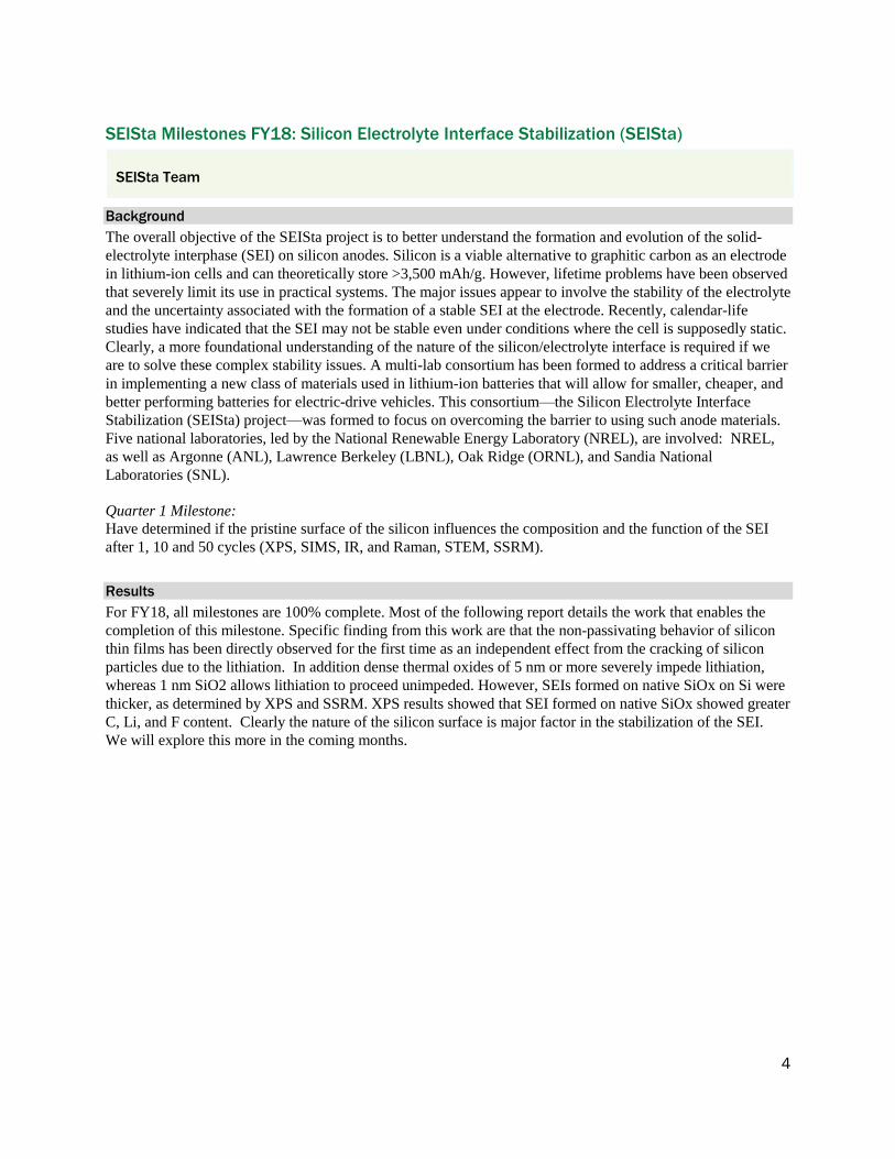
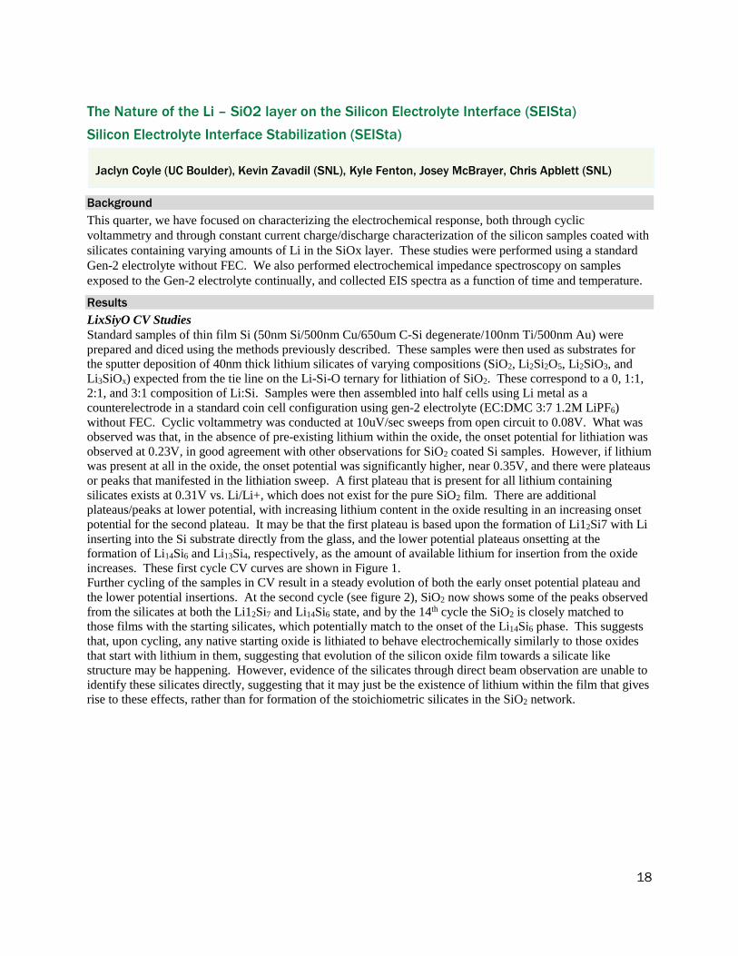
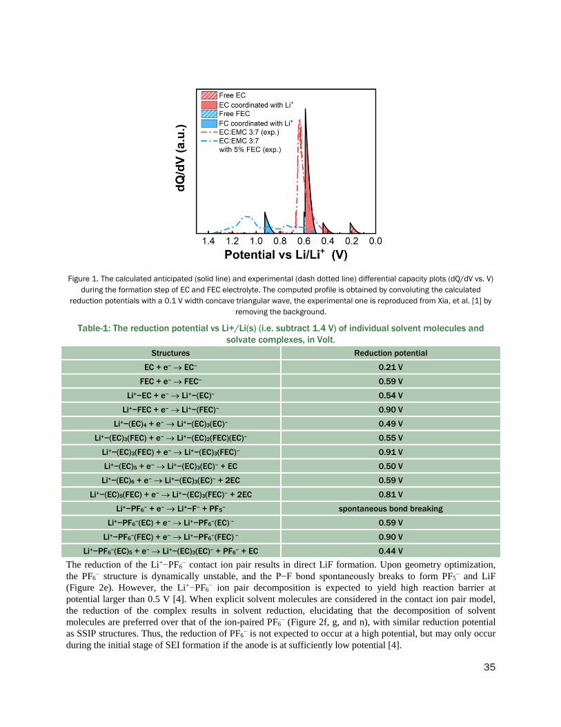