signalling, interlocking and indication devices for ... · the standard shall ensure that all shaft...
TRANSCRIPT

Signalling, Interlocking and Indication Devices
for Sinking Shafts
By Danie Bezuidenhout
Agenda
Our Approach to Safety
Objective
Hazard Identification
Testing of Safety Devices
Conclusion
2

Vertical ShaftsSinking Experience
3
Kilometres of Shafts Sunk

Our Approach to Safety
4

Objective
To provide a Standard for Engineers, Technical
Assistants, Engineering Foreman, Winding Engine
Drivers and Artisans for installing, operating and
maintaining the signalling, interlocking and indication
devices on Shaft Sinking operations
5

Hazard Identification
26 Safety Devices identified and implemented– zero tolerance to hazards & risks
The standard shall ensure that all Shaft Sinking Winders shall have the same signalling, interlocking and indication devices All installations shall be commissioned, operated and maintained to the same standard– familiarity of safety devices
The combination of the Safety Devices have proven effective in Vertical Shaft Sinking operations
6

Hazard Identification
7
Headgear Area
Safety Devices14
Bank AreaSafety Devices3
Station Area
Safety Device1
Stage Area
Safety Devices6
Shaft Bottom
Safety Devices2

Headgear Area Safety Devices
1. Load Cells2. Jack Catches3. Headgear Ultimate4. Camgear Overwind5. Lilly Controller Overwind6. Overspeed Prevention Device7. Wrong Direction Device
(Phillips Device)
8. Tip Zone Indication9. Visual Display10. Crosshead Position Monitoring11. Crosshead Arrestor12. Lazy Chain Park Arrangement13. Chute Position Indication14. Crosshead Separation
8

Headgear Area Safety DevicesLoad Cells
9
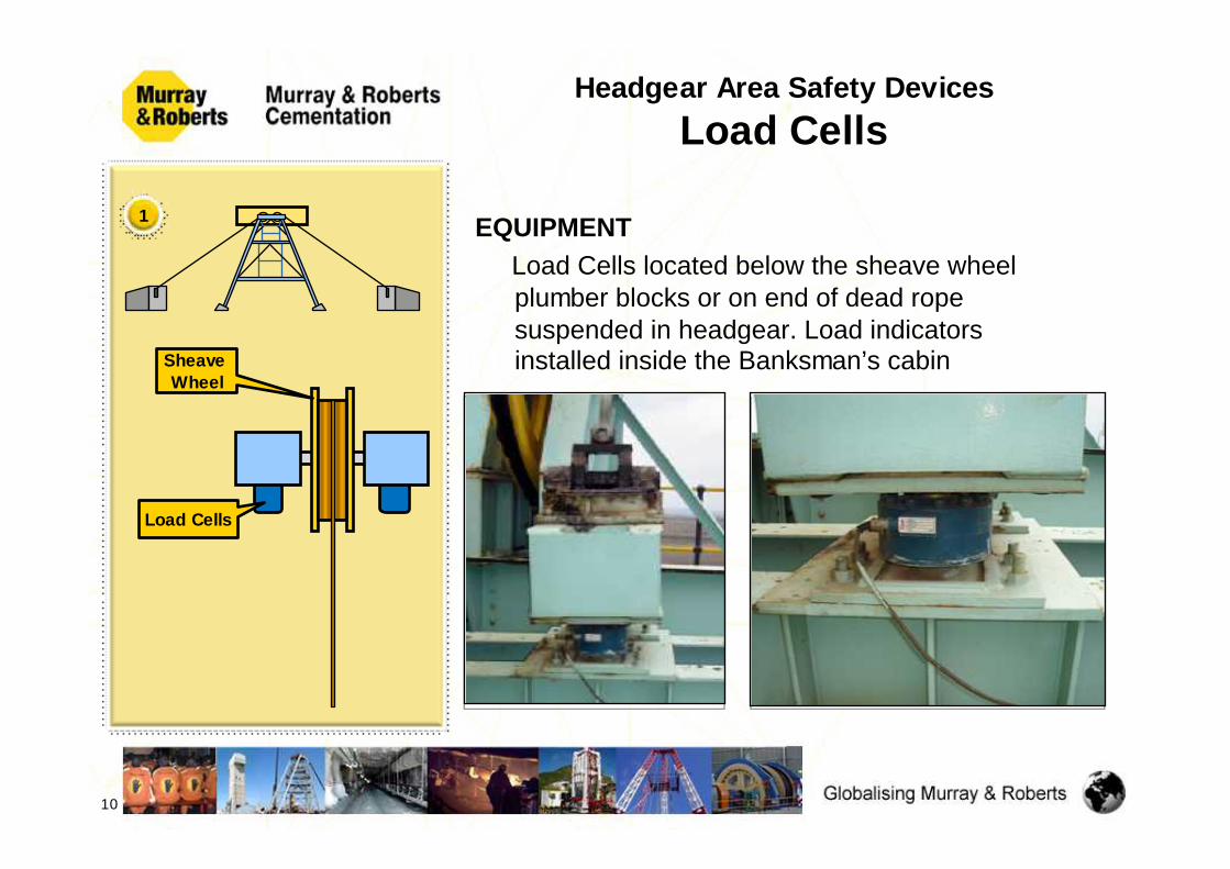
PURPOSE To monitor the total mass of a sinking stage, where the mass is critical to operations of the stage winder and stage ropes
INTERLOCKINGNot interlocked
INDICATIONDigital indicators displaying total suspended mass in Banksman cabin.
Sheave Wheel
Load Cells
1
10
EQUIPMENT Load Cells located below the sheave wheel plumber blocks or on end of dead rope suspended in headgear. Load indicators installed inside the Banksman’s cabinSheave
Wheel
Load Cells
1
Headgear Area Safety DevicesLoad Cells
Headgear Area Safety DevicesJack Catches
11
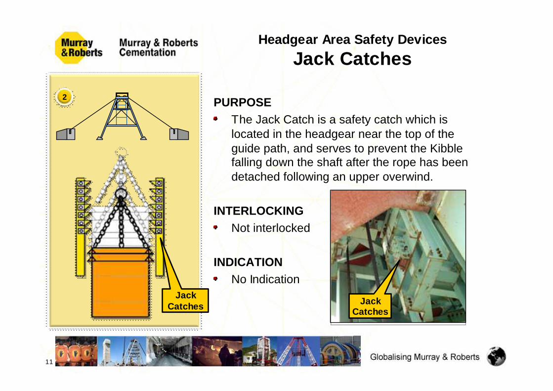
2 PURPOSE The Jack Catch is a safety catch which is located in the headgear near the top of the guide path, and serves to prevent the Kibble falling down the shaft after the rope has been detached following an upper overwind.
INTERLOCKINGNot interlocked
INDICATIONNo Indication
JackCatches Jack
Catches

Headgear Area Safety DevicesJack Catches
EQUIPMENTIt consists of a series of hinged lugs which protrude into the compartment. Steel guides must be fitted with the Jack Catches The Kibble is equipped with catch rings that will engage with the Jack Catches to hold the weight of the kibble.The Primary Jack Catch device is the Button, which is above the Rope Socket, this device will hold the Crosshead in position and prevent the Rope Attachment from falling into the Kibble
12

Headgear Area Safety DevicesHeadgear Ultimate Overwind
13
3
PURPOSE To trip out the motor / main winder circuit breaker as well as to activate the safety circuit before the crosshead and kibble enters the Jack Catches.
This is entirely dependent on the design of the headgear and stretch in the ropes, but is normally about 1m to 2m from the bottom of the Jack Catches
INTERLOCKINGIn the event of an upper overwind, this device must trip the motor / main circuit breaker.
Power can only be restored by the Engineer

Headgear Area Safety DevicesHeadgear Ultimate Overwind
EQUIPMENT
A “Tarzan” wire, pulley, counter weight and limit switch mounted below the Jack Catches, inside a pipe arrangement
A bi-directional switch is used to ensure fail to safe in all modes
14

Headgear Area Safety DevicesCamgear Overwind
15
4 PURPOSE
This device, which is driven separately from the Lilly Controller, has a mechanical input from the Winder Drum Ring Gear. It is another device that has overwind protection. It also provides the fixed distance of the end-of-wind from top to bottom of the shaft
INTERLOCKING
To trip the winder in an upper overwind condition just before the ultimate overwind trip is activated. Camgear

Headgear Area Safety DevicesCamgear Overwind
EQUIPMENTThis arrangement provides a series of cams secured on a shaft.Different cams activate electrical switches for the particular selected functions. One of these functions shall be the camgear overwind and must be arranged to trip the winder in an upper overwind condition just before the ultimate overwind trip is activated.
16
Camgear

Headgear Area Safety DevicesLilly Controller Overwind
17
5 PURPOSE This overwind protection device is a mechanical system that operates several switches incorporated in the winder safety circuit. This provides an end of travel trip, which is brought into action when the conveyance is overwind
INTERLOCKINGConnected in the safety circuit in such away as to prevent restarting after an overwind. Except in the right direction with the backing out facility
EQUIPMENTLilly Controller

Headgear Area Safety DevicesOverspeed Prevention Device
18
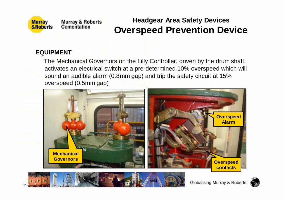
6 PURPOSE The purpose of these devices is to monitor the speed of the conveyances throughout the wind as it approaches the end zones of the wind
INTERLOCKINGConnected in the safety circuit to alarm and trip the winder at the above mentioned zones
CreepZones
BankDoorArea
Headgear Area Safety DevicesOverspeed Prevention Device
19
EQUIPMENTThe Mechanical Governors on the Lilly Controller, driven by the drum shaft, activates an electrical switch at a pre-determined 10% overspeed which will sound an audible alarm (0.8mm gap) and trip the safety circuit at 15% overspeed (0.5mm gap)
Overspeed contacts
Mechanical Governors
Overspeed Alarm
Headgear Area Safety DevicesWrong Direction Device
(Phillips Device)
20
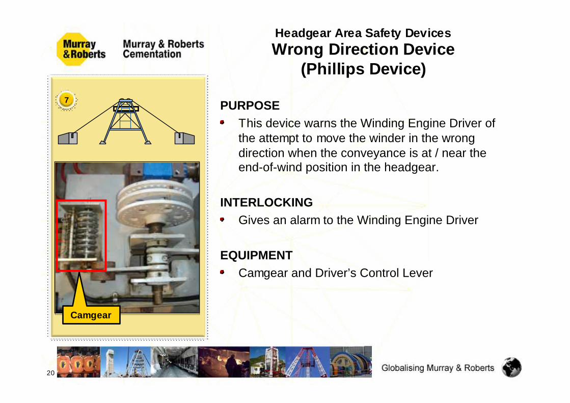
PURPOSE This device warns the Winding Engine Driver of the attempt to move the winder in the wrong direction when the conveyance is at / near the end-of-wind position in the headgear.
INTERLOCKINGGives an alarm to the Winding Engine Driver
EQUIPMENTCamgear and Driver’s Control Lever
7
Camgear

Headgear Area Safety DevicesTip Zone Indication
21
PURPOSE To indicate to the Winding Engine Driver the position of the Kibble in the Headgear by means of Limit or Magnetic switches
INTERLOCKINGThe Tip Zone is set to operate ± 100mm above the Crosshead arresting positionIn this zone the Crosshead Arrestor & Swing Chute can be operated only if the bank doors are closedWhen the Crosshead is lowered onto the Arrestors, the Swing Chute, Arrestors and Bank Doors cannot be operated The power supply to the Arrestor and Swing Chute is activated only when the Kibble and Crosshead enters the tipping zone
8

Headgear Area Safety DevicesTip Zone Indication
22
EQUIPMENTMagnetic Switch, Infrared Beam or Mercury Switch
8

PURPOSE The cameras are positioned in the Headgear to give the Winding Engine Driver a clear view of the Tipping Path of the Kibble entering the Headgear from the Bank Doors through the full tipping cycle
Two monitors, one for each compartment,are installed inthe WED’s cabin
EQUIPMENTCCTV Cameras
Headgear Area Safety DevicesVisual Display
23
9

PURPOSEThe Bi-Stable ensures that the Crosshead accompanies the descending Kibble during the lowering of the Conveyance out of the Headgear
INTERLOCKINGThe winder will trip out if the Crosshead does not activate the Bi-Stable
Headgear Area Safety DevicesCrosshead Monitor (Bi-Stable)
24
10
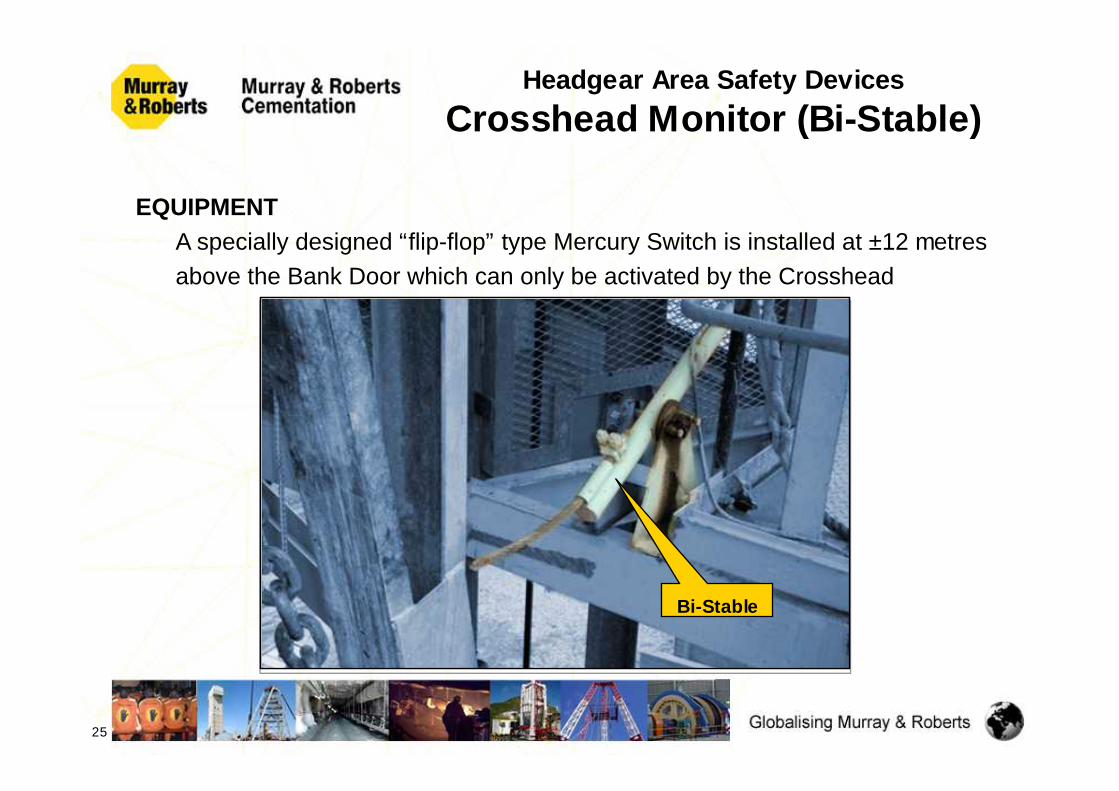
EQUIPMENTA specially designed “flip-flop” type Mercury Switch is installed at ±12 metresabove the Bank Door which can only be activated by the Crosshead
Headgear Area Safety DevicesCrosshead Monitor (Bi-Stable)
25
Bi-Stable
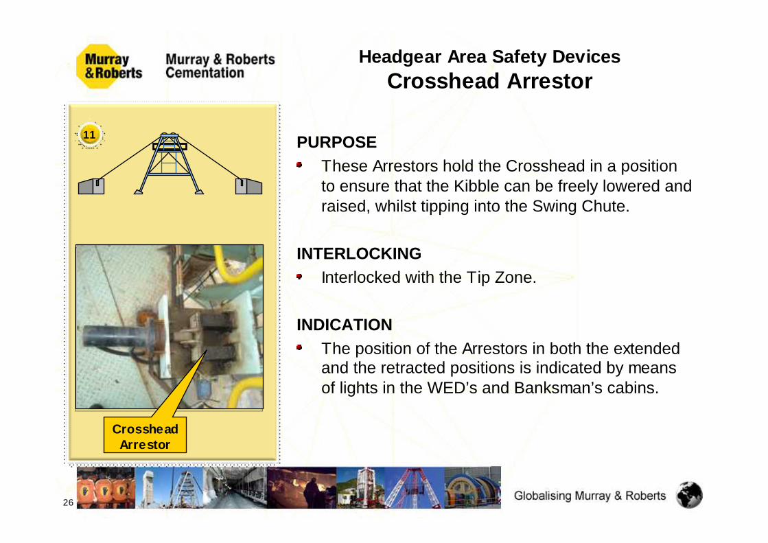
PURPOSE These Arrestors hold the Crosshead in a position to ensure that the Kibble can be freely lowered and raised, whilst tipping into the Swing Chute.
INTERLOCKINGInterlocked with the Tip Zone.
INDICATIONThe position of the Arrestors in both the extended and the retracted positions is indicated by means of lights in the WED’s and Banksman’s cabins.
Headgear Area Safety DevicesCrosshead Arrestor
26
11
Crosshead Arrestor

EQUIPMENTTwo cylinder operated Arrestors are provided in each compartment.
Positional Proximity Type Limit Switches are fitted on each Arrestor, two in series per compartment.
The Crosshead Arrestor device is supported on a hinge point and kept in a lateral position by two 8mm brass bolts, that will shear when the Crosshead and Kibble is raised with the Arrestor in the fully extended position
Headgear Area Safety DevicesCrosshead Arrestor
27
Crosshead resting on
the Arrestor

PURPOSE To ensure that the chain is clear from the Kibble and in the “park” position after the Kibble has been tipped
INTERLOCKINGThe Winder will trip out when the hook is removed from “park” position, and the Swing Chute is in the retracted positionWhen the Crosshead is lowered onto the Arrestors, and the Swing Chute is in the tipping position, this will override the Winder Trip, and allow the Kibble to be tipped and raised back to the tip position.
INDICATIONThe position of the Lazy Chain is indicated by means of lights in the WED’s and Banksman’s cabins
Headgear Area Safety DevicesLazy Chain Park Arrangement
28
12
Lazy Chain in “park”position
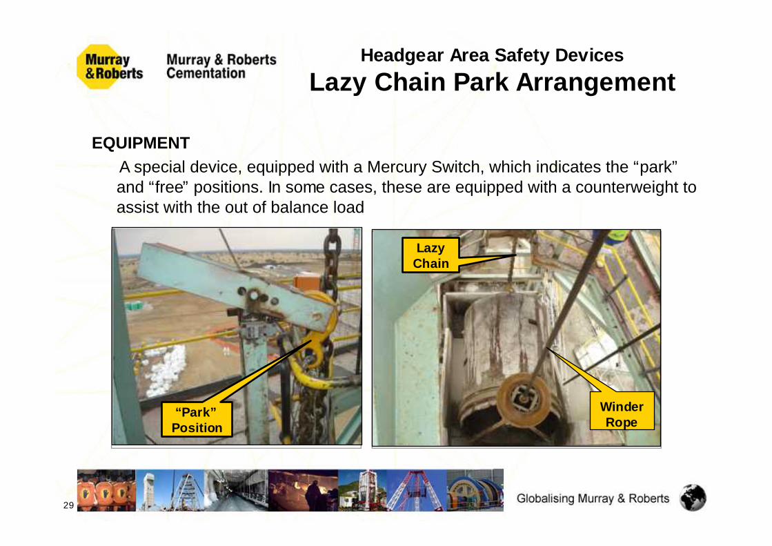
EQUIPMENTA special device, equipped with a Mercury Switch, which indicates the “park”and “free” positions. In some cases, these are equipped with a counterweight to assist with the out of balance load
Headgear Area Safety DevicesLazy Chain Park Arrangement
29
LazyChain
“Park”Position
WinderRope

PURPOSE To indicate to the Winding Engine Driver and Banksman when the chute is in the open (tipping) or retracted and latched position.
INTERLOCKINGCrosshead must be in the tip zone.Bank doors must be closed.When the operator actuates the tipping system the Crosshead Arrestors will first move into position before the Swing Chute moves into its tipping position.
INDICATIONLights indicate the “chute open” and “chute closed” positions in the Banksman’s and WED’s cabins
Headgear Area Safety DevicesChute Position Indication
30
13
SwingChute
Kibble Jack
Catches
Button Jack
Catches
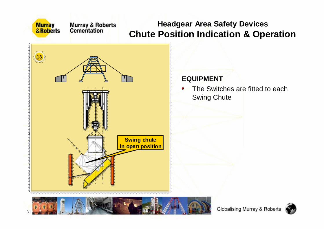
EQUIPMENTThe Switches are fitted to each Swing Chute
Headgear Area Safety DevicesChute Position Indication & Operation
31
13
Swing chutein open position

PURPOSE To indicate to the driver when Crosshead separation has taken place, i.e.:
– In Headgear when tipping – On the Stage when landing the Crosshead– Abnormal separation in the Shaft– Signalling from kibble to WED whilst persons are travelling
INDICATIONLights for each compartment in WED’s cabinAdditional audible alarm in WED’s & Banksman’s cabins for shaft Crosshead separationThe audible alarm is overridden when the Crosshead Arrestors are extended to hold the Crosshead, and when the Crosshead has landed onto the Stage ArrestorsThe audible Alarm is also sounded briefly after the Crosshead has picked up from the Stage Arrestors.The WED can receive signals from persons whilst travelling
Headgear Area Safety DevicesCrosshead Separation
32
Crosshead Separation
Switch
14
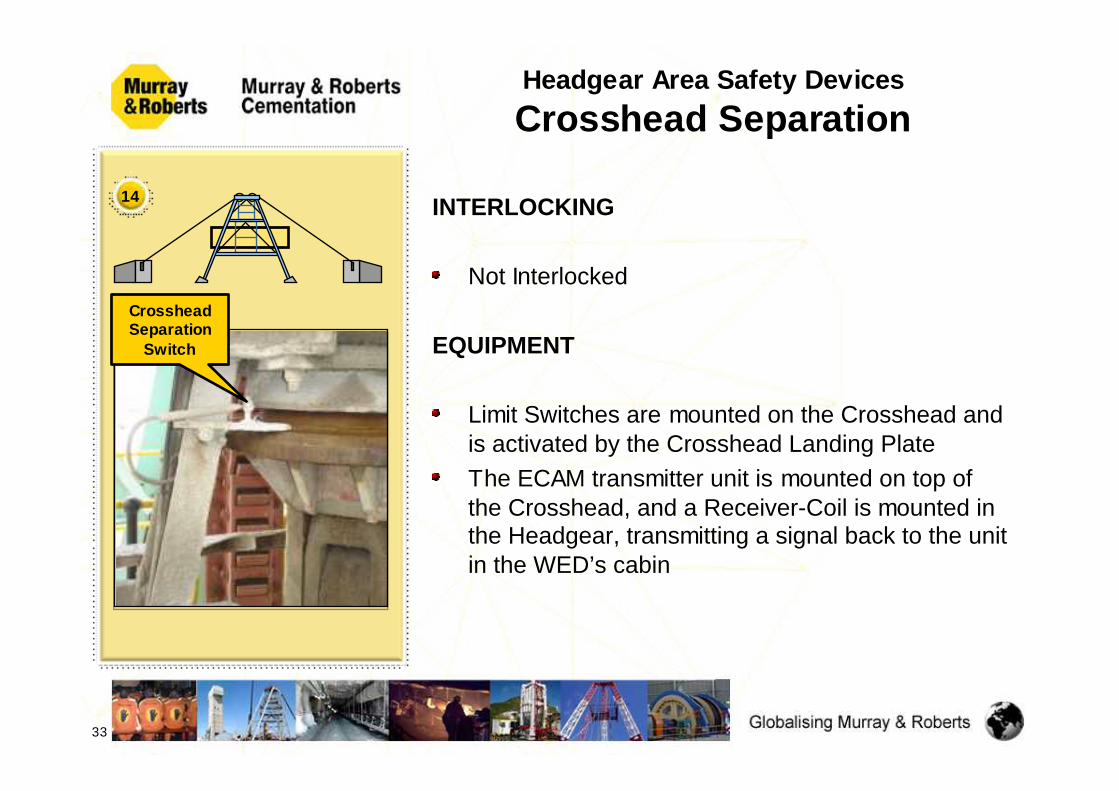
INTERLOCKING
Not Interlocked
EQUIPMENT
Limit Switches are mounted on the Crosshead and is activated by the Crosshead Landing PlateThe ECAM transmitter unit is mounted on top of the Crosshead, and a Receiver-Coil is mounted in the Headgear, transmitting a signal back to the unit in the WED’s cabin
Headgear Area Safety DevicesCrosshead Separation
33
14
Crosshead Separation
Switch
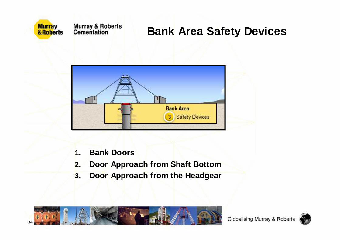
Bank Area Safety Devices
1. Bank Doors2. Door Approach from Shaft Bottom3. Door Approach from the Headgear
34

1
PURPOSE The Bank Doors provides protection for persons working in the Shaft and on the Stage from falling objects. Lights indicate the position of the Bank Doors to the WED and Banksman
INTERLOCKINGThe following interlocking is applicable;Ø The Kibble can only enter the Tip Zone if the
Bank Doors are closed.Ø If the Kibble travels through the Bank Door
Area, then the doors cannot be closed.
Bank Area Safety DevicesBank Doors
35
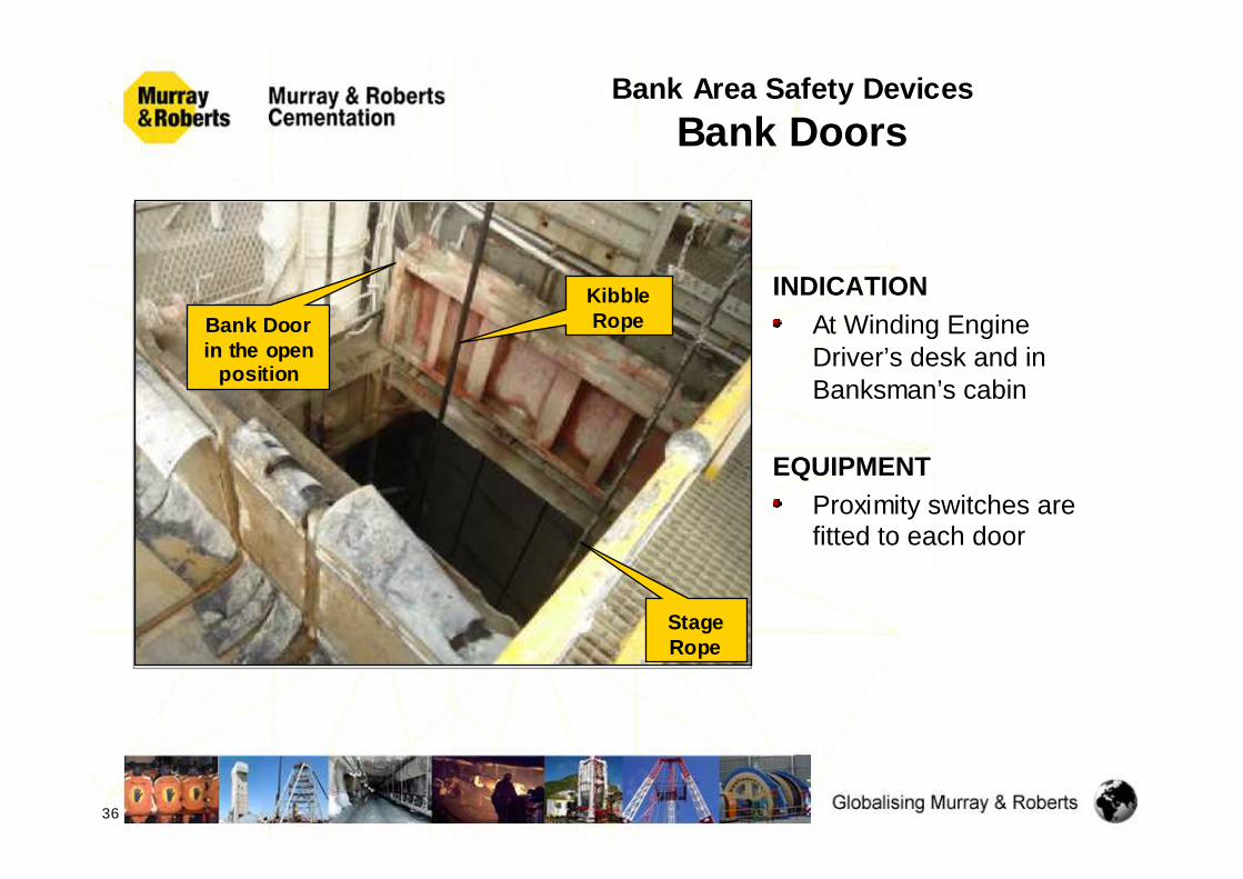
INDICATIONAt Winding Engine Driver’s desk and in Banksman’s cabin
EQUIPMENTProximity switches are fitted to each door
Bank Area Safety DevicesBank Doors
36
Bank Doorin the open
position
KibbleRope
StageRope

PURPOSE To prevent the ascending Crosshead from crashing into the closed Doors The ascending Kibble will trip the winder 3 to 5 turns from the closed Doors. If the Doors are in the “closed” position, the Backing-out Switch may not be used to override this trip
INTERLOCKINGThe Winder is interlocked with the Bank Doors and will trip if the Doors are closed when the Crosshead approaches beyond the set point
INDICATIONMarked on the Depth Indicator by the WED
Bank Area Safety DevicesDoor Approach from Shaft Bottom
37
2

Bank Area Safety DevicesDoor Approach from Shaft Bottom
38
EQUIPMENTCams and Limit Switches fitted to the Depth Indicator, Lilly Controller or Mechanical Camgear.
Set to trip the Winder 3 to 5 turns from the closed doors.
Note: The tripping distance is dependant on the true stopping distanceof the conveyance as determined by actual dynamic testing
2

PURPOSE The Winder shall trip ± 5m above the Bank Doors. If the Doors are in the “close” position, the WED must use the Foot Backing-out Switch to lower the Kibble onto the Bank DoorsThis will allow the WED to lower the Crosshead, Kibble or Attached Loads onto the Bank Doors
INTERLOCKINGInterlocked to trip the Winder before reaching the Doors
INDICATIONAudible and visible Alarm in Driver’s cabin
EQUIPMENTCam on Lilly Controller, Camgear, Backing-out Foot Switch. Audible and Visible Alarms will activate in Driver’s cabin indicating the override condition
Bank Area Safety DevicesDoor Approach from Headgear
39
3
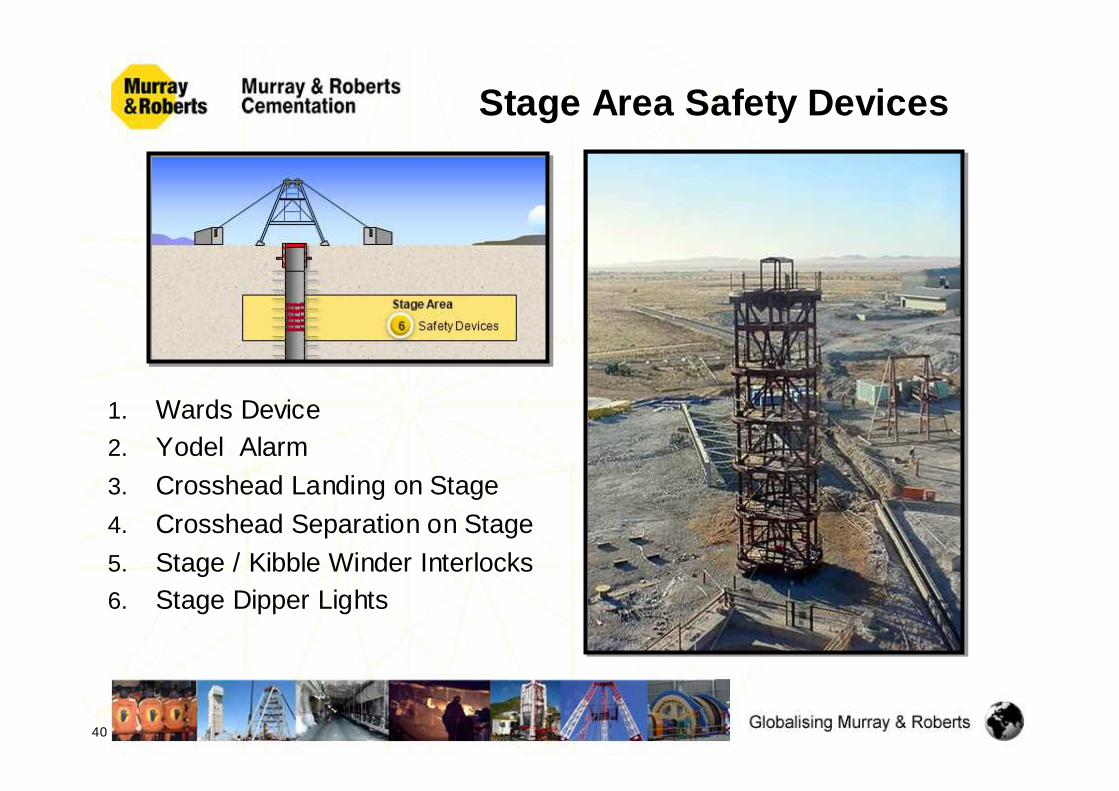
Stage Area Safety Devices
1. Wards Device2. Yodel Alarm3. Crosshead Landing on Stage4. Crosshead Separation on Stage5. Stage / Kibble Winder Interlocks6. Stage Dipper Lights
40

CreepZone
PURPOSE To prevent the descending Kibble / Attached Load from entering the Stage without receiving a signal from the Top Deck Bell Ringer.
EQUIPMENTProximity Switches and Cams mounted on the Lilly Controller or Camgear.
INDICATION Nil
Stage Area Safety DevicesWards Device
41
1

INTERLOCKINGInterlocked with the Kibble Winder. The Winder will trip out if the Top Deck Bell Ringer fails to signal the Winding Engine Driver to proceed through the Stage. The Wards device can be overridden by the WED when no persons are underground or on the Stage (first trip after the blast). This is done by removing the Kibble / Stage Winder Change Over Key, inserting it into the remote key position and turning the key to pulse a clear “stage”signal. The key is removed and re-inserted in the Kibble / Stage winder key switch.
Stage Area Safety DevicesWards Device
42
CreepZone
1
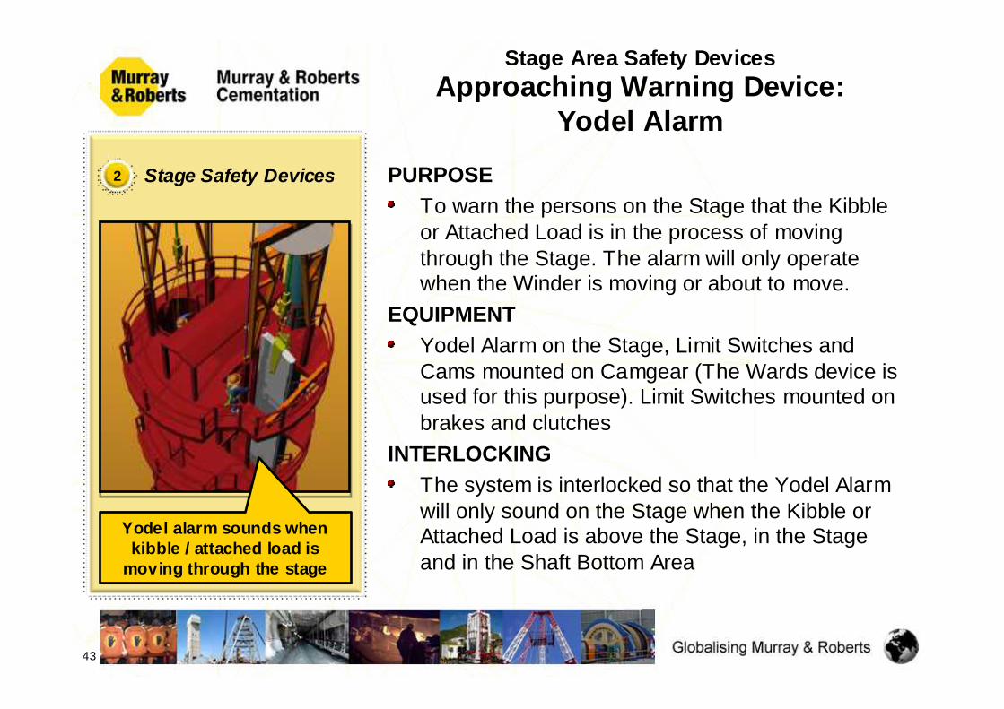
PURPOSE To warn the persons on the Stage that the Kibble or Attached Load is in the process of moving through the Stage. The alarm will only operate when the Winder is moving or about to move.
EQUIPMENTYodel Alarm on the Stage, Limit Switches and Cams mounted on Camgear (The Wards device is used for this purpose). Limit Switches mounted on brakes and clutches
INTERLOCKINGThe system is interlocked so that the Yodel Alarm will only sound on the Stage when the Kibble or Attached Load is above the Stage, in the Stage and in the Shaft Bottom Area
Stage Area Safety DevicesApproaching Warning Device:
Yodel Alarm
43
2
Yodel alarm sounds when kibble / attached load is
moving through the stage
Stage Safety Devices

PURPOSE To indicate to the WED that the Crosshead has landed on the Stage, and to override the Crosshead Separation Alarm
EQUIPMENTA Switch is mounted on the Landing Plate on the Stage.
INTERLOCKING Not interlocked
INDICATION Indication Light on the Driver’s desk
Stage Area Safety DevicesCrosshead Landing on Stage
44
3 Stage Safety Devices
Crosshead Landing on
Stage

PURPOSE
Same as Crosshead separation in Headgear
To indicate to the Driver when Crosshead separation has taken place at the Stage when landing the Crosshead
Stage Area Safety DevicesCrosshead Separation on Stage
45
4 Stage Safety Devices
Crosshead
ECAM Transmitter
Coil
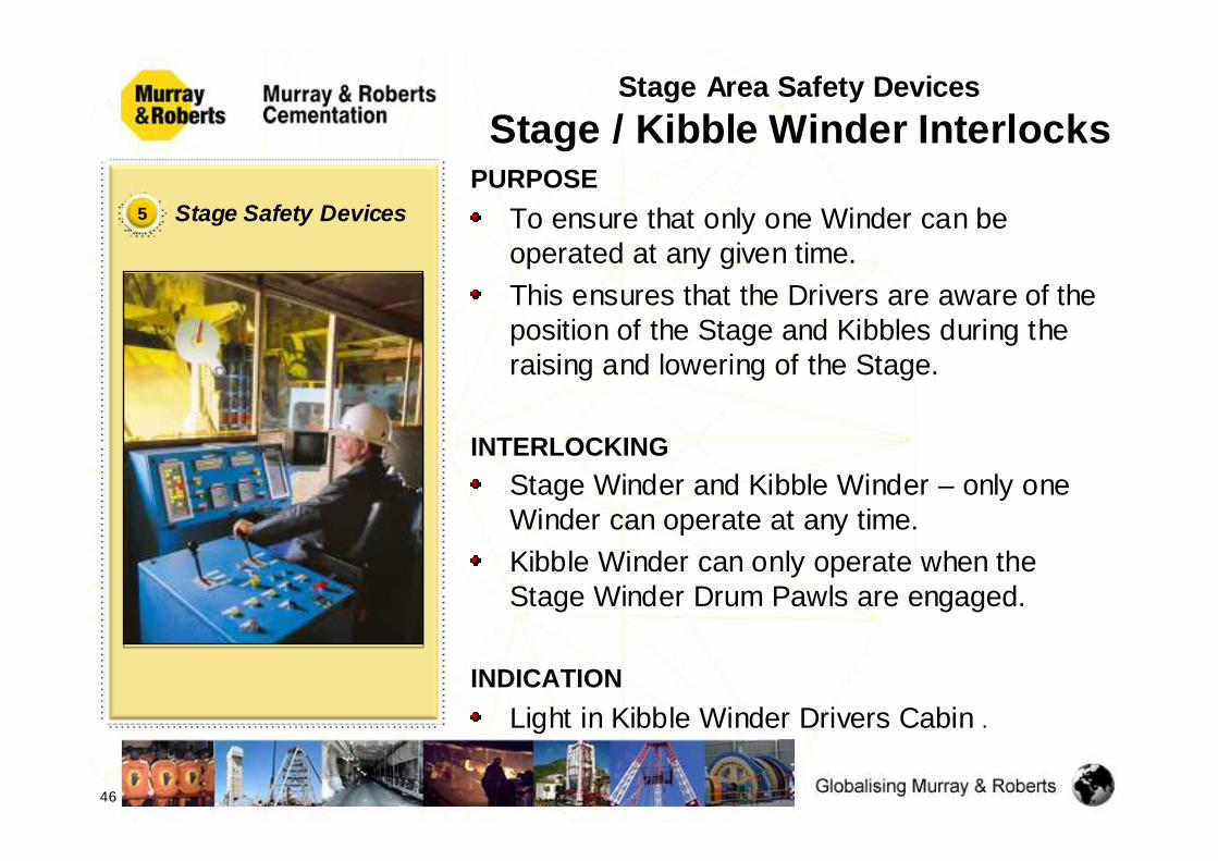
PURPOSE To ensure that only one Winder can be operated at any given time. This ensures that the Drivers are aware of the position of the Stage and Kibbles during the raising and lowering of the Stage.
INTERLOCKING Stage Winder and Kibble Winder – only one Winder can operate at any time.Kibble Winder can only operate when the Stage Winder Drum Pawls are engaged.
INDICATIONLight in Kibble Winder Drivers Cabin .
Stage Area Safety DevicesStage / Kibble Winder Interlocks
46
5 Stage Safety Devices

EQUIPMENT
Key switches are provided on each of the Winders Driver’s desks. Both switches operate with the same key. The key can only be removed when the Switch is in the “off” position. The key in the “off” position isolates the operating and signalling arrangements of either Winder.Limit Switches are fitted to the Pawls of the Stage Winder
Stage Area Safety DevicesStage / Kibble Winder Interlocks
47
5 Stage Safety Devices
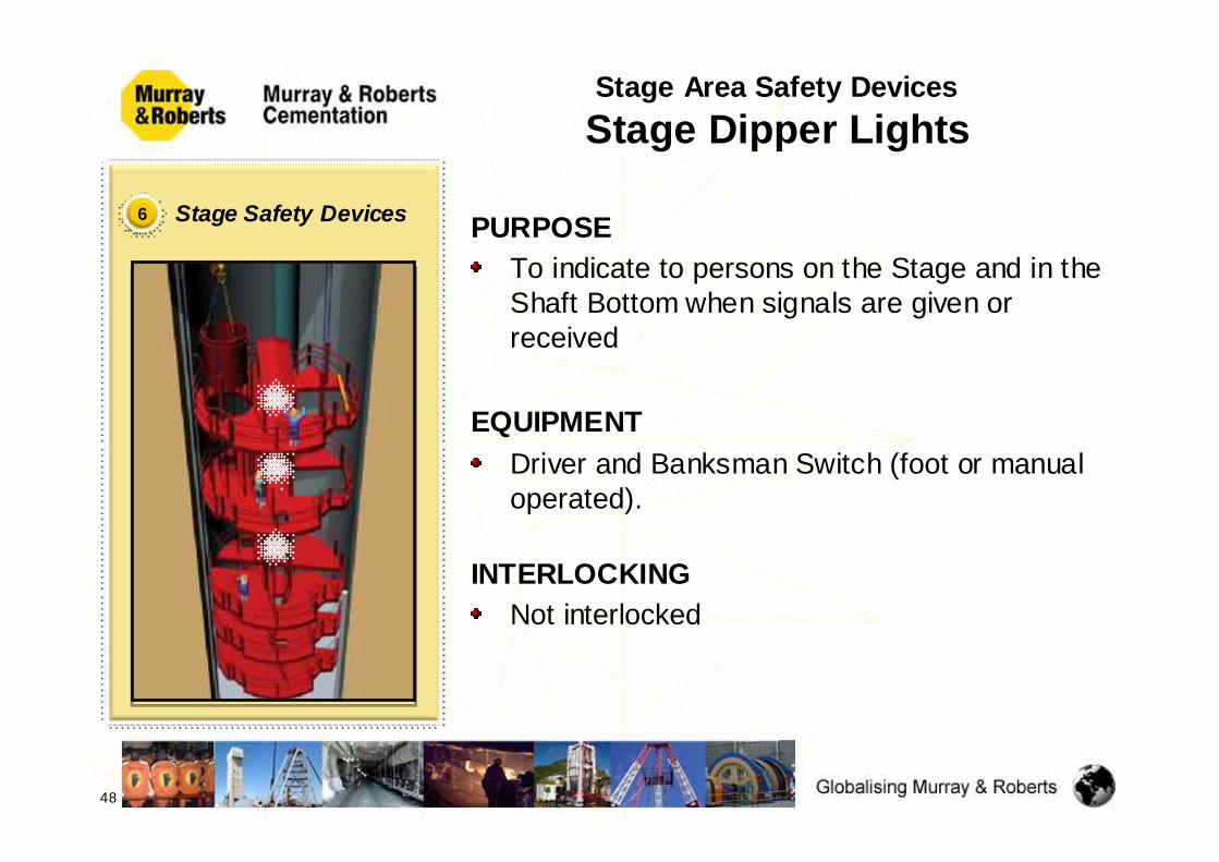
PURPOSE To indicate to persons on the Stage and in the Shaft Bottom when signals are given or received
EQUIPMENTDriver and Banksman Switch (foot or manual operated).
INTERLOCKINGNot interlocked
Stage Area Safety DevicesStage Dipper Lights
48
6 Stage Safety Devices

Station & Shaft BottomSafety Devices
Station Safety Devices:1. Drawbridges, Lock and Call Bell
Systems
49
Shaft Bottom Safety Devices:1. Lower Underwind Protection2. Lashing Unit - Boom Park
position indication

PURPOSEDrawbridges at Stations or Landings are used for people access to the conveyances.
EQUIPMENT Drawbridges are fitted with Limit Switches that are interlocked into the Winder Safety Circuit.Standard Lock & Call Bell System installed
INTERLOCKINGConnected in the Safety Circuit in such a way as to prevent winding, if the Drawbridge is not fully retracted and positively secured
Station Area Safety DevicesDrawbridges, Lock and Call Bell
Systems
50
1 Station Safety Devices
DrawBridges

PURPOSE This Lower Underwind Protection Device is a mechanical system that operates a switch incorporated in the Winder Safety Circuit. It provides an end of travel trip, which is brought into action when the Conveyance is overwind past the lower limits.
EQUIPMENTConsists of a Switch on the Lilly Controller that gets activated by a pre-set Cam on the dial of the Lilly Controller. This Cam shall be set continuously whilst the shaft is sunk deeper
INTERLOCKINGConnected in the Safety Circuit in such a way as to prevent restarting after an overwind. Except in the right direction with the Backing Out Facility
Shaft Bottom Safety DevicesLower Underwind Protection
51
1 Shaft Bottom Safety Devices
ShaftBottom

PURPOSE This device only serves as an indication of the position of the Lashing Unit Boom in terms of the Kibble Compartments to the WED.It will indicate if the Boom is in the way of the descending Kibble in that particular Compartment. As an additional preventative Safety Instruction and Procedure, the WED may only proceed to the bottom, below the overhang position, if the Bottom Deck Bell Ringer gives the WED a signal.
Shaft Bottom Safety DevicesLashing Unit Boom Position
52
2 Shaft Bottom Safety DevicesLashing Unit
Boom

Testing of Safety Devices
All the safety devices are tested by the appointed persons at the specified regular intervals.
53

Conclusion
All the above Safety Devices have been identified and implemented, on all our Vertical Shaft Sinking Projects, as a Comprehensive Winder Safety System
The combination of these Safety Devices and the Standardisation thereof, has contributed to a Safe Working Environment in Murray & Roberts Cementation
Murray & Roberts Cementation is a World Class,Shaft Sinking Contractor
54

Thank You,
Questions?
Danie BezuidenhoutSite Engineer
Impala Nº 20 Shaft Project
55