signalling and interlocking
TRANSCRIPT

SIGNALLING
AND
INTERLOCKING

Introduction
Signalling is the device by which the
movement of trains is controlled
Highly important in terms of safety
Trains can be operated efficiently, utilization of
tracks and tracks can be done at maximum
levels
Signalling includes signals, points, blocks and
other equipment;
Objects of Signalling
Maintain safe distance between trains running in
the same direction on a single line.
Safe distance between trains which are
approaching or crossing a crossing.
To run the trains at restricted speeds during
repair works
At junctions to prevent the trains from colliding
Objects of Signalling
At the diverging tracks to give indication about
the direction to move
In marshalling yards, to provide safety against
shunting
To provide facilities for the maximum use of
track and rolling stock
Increase the safety
Classification of signals
Depending on the operational characteristics
Fog or audible or detonating signals
Visual indication hand signals
Visual indication fixed signals
Depending on the functional characteristics
Stop or semaphore type signals
Warner signals
Shunting signals
Coloured light signals

Depending on the location characteristics Outer receptional signals
Home receptional signals
Starter signals
Advance starter signals
Special signals Routing signals
Calling on signals
Point indicators
Repeater or co-acting signals
Modified lower quadrant semaphore signals
Miscellaneous signals

CLASSIFICATION OF SIGNALS
SIGNALS
FUNCTION PURPOSELOCATION OPERATION
STOP
WARNER
DISC
COLORED
OUTER
HOME
STARTER
ADVANCE
ROUTING
REPEATER
CALL ON
HAND
FIXED
DETONATING


CLASSIFICATION OF SIGNALS
Controlling signals
Which are mandatory to
observe for train movement

CLASSIFICATION OF SIGNALS
Indicating signals
Correspond to the traffic signs of
highways. Also mandatory to
observe.

CLASSIFICATION OF SIGNALS
Warning signals
They provide a pre-handwarning to the driverabout the controllingsignals ahead. These onlyenhance the efficiencyand provide a furthersafety caution.

Detonating Signals
Used when hand and fixed signals or not visible(foggy and cloudy conditions)
Also used during emergencies (derailment, accidents etc.,)
These are in the form of detonators fixed on the top of rails
When engine passes over it explodes with big sound and alerts the driver to stop the train.
3 to 4 detonators are placed at an interval of about 10 to 15m at 400 to 500m ahead.

Hand Signals
Given by the guard using coloured flags or by
bare arms
During night times kerosene lamps fitted with
movable green, red and yellow coloured
glasses are used.
o Green - proceed
o Red - dead stop
o Yellow – proceed with caution
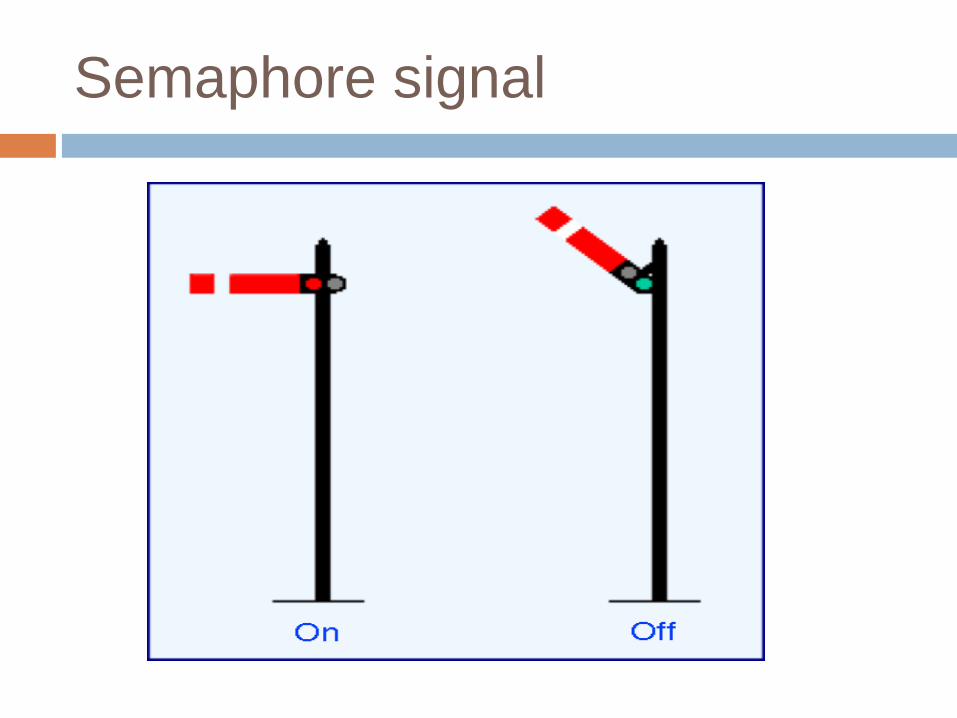
Semaphore Signals
Consist of a vertical post on which a movable arm is pivoted at the top.
Arm can be kept horizontal or it can be inclined at 45 degree to horizontal
Outer end of arm is 2.45cm broader than that at post.
Movable arm is controlled by means of levers and cables from the cabin.
Spectacles of red and green or fixed in the arm
These are fixed on the left hand side of track, with spectacles towards driver.

Horizontal arm indicates “ DANGER –STOP ”
and the inclined arm indicates “ CLEAR –
PROCEED”.
In the day time position of arm indicates the
signal.
During the night time light of lamp passing
through spectacle gives the signal.
Semaphore signal

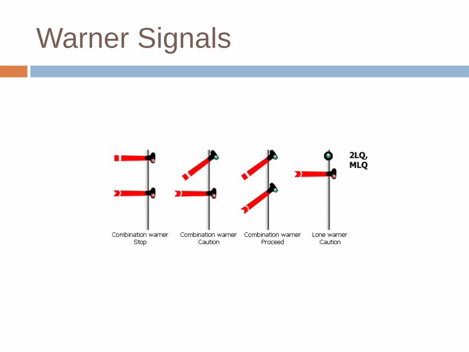
Warner Signal
This is similar to semaphore signal
Difference is it contains a fish tailed arm
These signals are placed ahead the semaphore signals to warn the driver before entering the railway station.
When the arm is horizontal – indicates signal ahead is stop
Warner signals are placed 540m away from the first stop signal.
Some times warner signals are provided with yellow lights instead of red to distinguish them from semaphore signals during nights.

Some times both warner and semaphore
signals are placed on the same pole
Both horizontal – stop line not clear
Semaphore lower, warner horizontal – proceed
with caution
Both lowered – proceed on with confidence
(this section and next section both are clear)
Warner Signals

Shunting Signals
Also called as disc or ground signals or miniature semaphore signals
Used during shunting operations
Consist of a circular disc painted white with a red band along its diameter.
Red band is horizontal – stop
Red band is inclined – proceed
Similar to semaphore these are also provided with lamp and colored glasses

Shunting signals
Coloured light signals
Used for automatic signalling these days
No moving arm is present
Give indication by electric light both during day
and night
o Red – Stop
o Green – Proceed
o Yellow – Proceed with caution


Outer Signal
This is the warner signal first seen by the
driver
Trains moving at high speed require certain
distance for stopping
Hence driver informed about the position in
advance that platform is clear or not.
This signal gives the position of stop signal
ahead.
As it is provided at some distance away from
station it is also called as distant or outer or
warner signal.

In the inclined or proceed position it indicates that track and
platform is clear and proceed normally without any danger.
In horizontal or stop position it indicates that the driver must
bring his train to halt within 90 m before outer signal and than
proceed to the home signal with caution
OUTER SIGNAL
OS

Home signal
It is next signal after outer signal towards
station
It is a simple semaphore signal and indicates
whether platform is clear or not

HOME SIGNAL
After the outer signal towards station is a stop signal and exactly
placed at the station limit is called home or stop signal. Its main
function is to protect the stations. The permission to enter the
platform is given by the operation of this signal. The maximum
unprotected distance between the signal and the point, it is
intended to protect is specified as 180 m due to its location at the
door of station, it is called home signal.
HSOHS
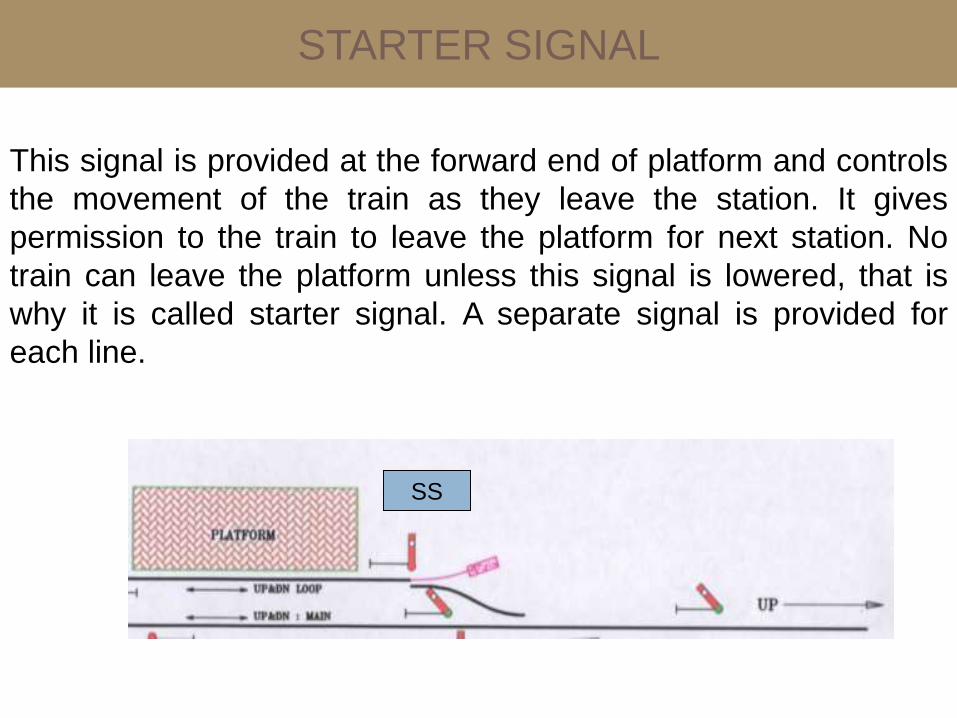
STARTER SIGNAL
This signal is provided at the forward end of platform and controls
the movement of the train as they leave the station. It gives
permission to the train to leave the platform for next station. No
train can leave the platform unless this signal is lowered, that is
why it is called starter signal. A separate signal is provided for
each line.
SS

ADVANCE STARTER SIGNAL
The limit of a station section lies between the home signal
and the advance starter signal. The signal which allows the train
to enter in block section is called advance starter signal. It is
always placed beyond the outer most set of the point connections.
These signals are placed about 180m beyond the last point or
switches.
ASS
SSHSOHS
station section

ROUTING SIGNAL
When many branch lines diverge in different directions from
the main line, it is very difficult to provide individual signal for each
line at the divergent point.
In such situations various signals for main line and branch
lines are fixed on the same vertical post. These signals are called
routing signal. Generally signal for main line is kept higher than
those for branch lines

REPEATING SIGNAL
When the view of the main signal is obstructed due to
some structures or on curves etc. some signals are used to repeat
the information of the main signal. Such signal are know as
repeating signal.

CALLING ON SIGNAL
These signal are similar to semaphore signal, but they
are smaller in size and are fixed on the same post below the
main signals. A calling on signal permits a train to proceed with
caution after the train has been brought to a halt by the main
signal. These are helpful when repair works are going on.
Signalling Systems
Absolute block system
Space interval system
Time interval system
Pilot guard system

Absolute Block System
This system involves dividing the entire length
of the track into sections called block sections.
A block section lies between two stations that
are provided with block instruments
The block instruments of adjoining stations are
connected through railway lines.
A token can be taken from the block
instrument of a particular station with the
consent of both the station masters.

Absolute Block system
In the absolute block system, the departure of a train from one station to another is not permitted until and unless the previous train has completely arrived at the next station.
i.e., trains are not permitted to enter the section between two stations at the same time.
Each station has two block instruments;
one for the station ahead and the other for the previous station
These are electrically interconnected

Time interval method
Trains are Spaced Over an length of a track in
such a way that , if the first train stops, the
following train driver should be able to stop the
train in sufficient distance without colliding with
the first one.
This type is used where traffic is less and
weight of the trains are less, e.g: Trams
This Type of System cannot be used in
Passenger rails since weight and traffic is High

Space interval method
In this method of “Control Over Movement”,
the length of the track is divided in to sections
called Blocks.
The Entry of a train in to the ‘Block’ is
controlled in such a way that only when it is
free, a train can be allowed to enter it.
This means that between two consecutive
trains , there is definite space interval.

Interlocking
Arrangement of of signals, points and other
appliances, so interconnected by mechanical
or electrical locking that their operation takes
place in a predetermined sequence to ensure
that conflicting movement of signals and points
do not take place and train runs safely.

Necessity
increase in the number of points and signals
Increase in speeds
Points and signals arranged in fool proof
manner. Conflicting movements are avoided
Helps in proper and safe working of the
system
Essentials
It should not be possible to turn a signal off unless all points for the line on which the train is to be received are correctly set, all the facing points are locked, and all interlocked level crossings are closed and inaccessible to road traffic.
The line should be fully isolated before the signal is turned off, i.e., no loose wagons should be able to enter this line.
After the signal has been turned off, it should not be possible to make adjustments in the points or locks on the route.

Essentials
It should not be possible to turn any two
signals off at the same time, as this can lead to
conflicting movements of the trains.
Wherever feasible, the points should be so
interlocked as to avoid any conflicting
movement

standards
1st standard : makes use of key interlocking
Running speed for trains restricted to 50kmph
2nd standard:
used on non trunk main routes
Operated mechanically or electrically
Speed less than 75kmph
3rd standard;
Makes used of mechanically or electrically interconnected
Uses latest interlocking techniques also.

Key Interlocking
Simplest method of interlocking
Involves the manipulation of keys in one form
or other
This type of interlocking is normally provided
with standard 1 interlocking
Arrangement of key interlocking is done as
below when a main line and branch line exist
on a single track.

Key interlocking
Point can be set either for main line or branch line
A, B are the keys for main and branch lines. At any
point only one of the keys can be taken out.
Lever frame operating the signals is provided with 2
signals and will be operated by keys A and B only.
If the train is to be received on main line, the key is
locked for point on main line, and A is taken out and
inserted in the lever for signal of main line.
Thus lowering the signal of main line.
This type of signal is called indirect interlocking.
If there are multiple lines succession interlocking will
be used.

Mechanical Interlocking
Improved form of interlocking compared to key
interlocking
Greater safety and less manpower
Done using plungers and tie bars
Plungers are of size 30cm x 1.6cm and have
notches in them
Tie bars are placed at right angles to plungers
and are provided with suitable shaped riveted
cast iron pieces (tappets) that exactly fit in
notches.

Mechanical interlocking
Main components are
Locking frame
Point frame
Signal fittings
And connecting devices
Levers are arranged in a row in the frame
Pulling a point lever operates the point to which it is connected through a steel rod.
Pulling a signal lever changes the signal by pulling the wire connecting the lever and signal.

Mechanical interlocking
This entire arrangement is provided in a
locking trough where tappets are provided,
which move at right angles to the plungers.
When lever is pulled, it causes the plunger
which it is connected to move.
Due to wedge action, the tappet
accommodated in the notch of the plunger is
pushed out at right angles to the movement of
plunger.

Mechanical interlocking
The motion gets transferred to the other
tappets which are connected to the other
tappets by means of tie rod.
Some tappets gets pushed in, some pushed
out as a result.
In case a tappet is free and pushed into the
notch, it locks the lever connected to that
plunger.
Else if it is already locked, it will come out of
notch, and the lever becomes free to be
operated.

Different cases of mechanical
interlocking
Normal interlocking:
Pulling one lever locks other lever in normal position
Back locking or release locking:
Lever in normal position locks the other lever in normal
position.
When pulled other lever released and is free to operate
When other pulled, first one gets locked in pulled position.
Both wall locking:
Once the lever is locked other lever locked in current
position.
Conditional locking:
Pulling one lever locks other lever only when certain
conditions are fulfilled.

Electrical interlocking
Achieved through electrical switches known as relays
Manipulation of relays achieves interlocking
In the place of plungers or in addition to plungers, lever locks are attached with levers.
These work by making use of the principle of electromagnetism.
Soft iron core wrapped inside a iron core turns into magnet when current passes through it.
An arrangement named armature is attached to this magnet.
Depending on whether the armature is attached or not interlocking works here.
This entire system is housed in a glass or metal box known as relay.

Panel interlocking
All points and signals are operated electrically
from a central location
The switches for operating these points and
signals are mounted on a panel, which also
bears the diagram of the yard layout
Electrical interlocking is achieved by means of
relays
Centralized controlling of greater area is great
advantage
With elimination of inter cabin controlling
greater number of trains can be run with less
staff.

Route Relay Interlocking
Improvement over panel interlocking
In panel interlocking each point in the line has to be individually setup with a switch and clearance of signal is obtained by operating the switch.
In R.R.I only a pair of switches are used for doing all these operations automatically.
Signal is also cleared in the similar automated manner
The main requirement for this type of interlocking is entire track needs to be track circuited.

Route Relay Interlocking
The conditions of track circuit and various indications of all signal are mirrored on the panel that carries the diagram of the yard.
By looking at these indications a panel operator can a panel operator can easily know whether a track is free or not.
Once the route is set to allow, the portion gets illuminated with white light.
If the route is occupied, it will show in red colour.
If the train has cleared the track, the lights will off.

The Automatic Warning System
(AWS)
It is a device that triggers the automatic application
of brakes if the signal is indicating danger and the
driver has not taken any action.
The system consists of a track device located at a
desirable braking distance at the rear end of the
first stop signal.
The track device is activated when the signal
indicates danger and is ineffective when the signal
is ‘clear’.
Alarm will sound if driver don’t take action during a
stop signal.
Then emergency brakes are applied automatically.
Different components.
Points:
Points are set mechanically and are kept in locks
and stretcher bars.
The mechanical arrangement for operating them
includes a solid rod and cranks.
Point locks, detectors and lock bars used for
controlling and directing the points.
Point locks
A point lock is provided to ensure that each point
is set correctly.
It is provided between two tongue rails and near
the toe of the switch assembly.
The point lock consists of a plunger, which moves
in a plunger casing.
The plunger is worked by means of a plunger rod,
which is connected to the signal cabin through a
lock bar.

Detectors:
Provided at all points
To detect any defect or failure in the connection
between points and levers
To ensure the correct signal is lowered
It can be mechanical or electrical
Lock bar
A lock bar is provided to make it impossible to
change the point when a train is passing over it.