© siemens ag 2014 3vt3 molded case circuit … molded case circuit breakers up to 630 a catalog...
TRANSCRIPT

3
Siemens LV 36 · 2014
3VT3 Molded Case Circuit Breakers up to 630 A
3VT3 Molded Case Circuit Breakers up to 630 A
3/2 General data3/3 Circuit breakers · Switch disconnectors
Accessories and Components3/4 Circuit breakers · Switch disconnectors3/5 Auxiliary switches · Auxiliary trip units3/6 Manual/motorized operating mechanism3/8 Mounting accessories3/9 Connecting accessories3/10 Further accessories
3VT3 Molded Case Circuit Breakers up to 630 A
3/11 Circuit breakers · Switch disconnectorsAccessories and Components
3/17 Trip units3/26 Auxiliary switches3/28 Auxiliary trip units3/30 Rotary operating mechanisms3/32 Mechanical interlocking and
parallel switching3/34 Motorized operating mechanism3/39 Mounting accessories for plug-in version3/42 Mounting accessories for withdrawable
version3/45 Insulating barriers and terminal covers
Project Planning Assistance3/47 Dimensional drawings
Catalog
Technical Information
LV36_2014.book Seite 1 Freitag, 31. Januar 2014 4:36 16
© Siemens AG 2014

3VT3 Molded Case Circuit Breakers up to 630 ACatalog
General data
3/2 Siemens LV 36 · 2014
3
■ Overview
2
3
45
68
11
12
1
7
13
9 10
27 28 29 3026
14
1517
16
18 22 23
19 20 21
24 25
Molded case circuit breakerPlug-in deviceWithdrawable deviceBox terminalsCircular conductor terminalMultiple feed-in terminalMultiple feed-in terminalRear connectionFront connectionAuxiliary conductor terminal
Rotary operating mechanismLateral rotary operating mechanismMechanical parallel switchingMechanical interlockingMechanical interlocking by Bowden wireMotor operating mechanismShunt trip unitUndervoltage trip unitConnecting cablePosition signallingCoding Set
Auxiliary switch NC/NOAuxiliary switch NC/NOAuxiliary switch, change-over contactAuxiliary switch, earlyLockingtype leverSealing insetAdditional cover forovercurrent releasesTerminal coverInsulating barriers
123456789
10
1112131415161718192021
22232425262728
2930
Connecting sets
Switching unit
Accessories for plug-in and withdrawable devices
Accessories
NS
O0_
0021
1b
LV36_2014.book Seite 2 Freitag, 31. Januar 2014 4:36 16
© Siemens AG 2014
3VT3 Molded Case Circuit Breakers up to 630 ACatalog
Circuit breakers · Switch disconnectors
3/3Siemens LV 36 · 2014* You can order this quantity or a multiple thereof.
3
■ Overview
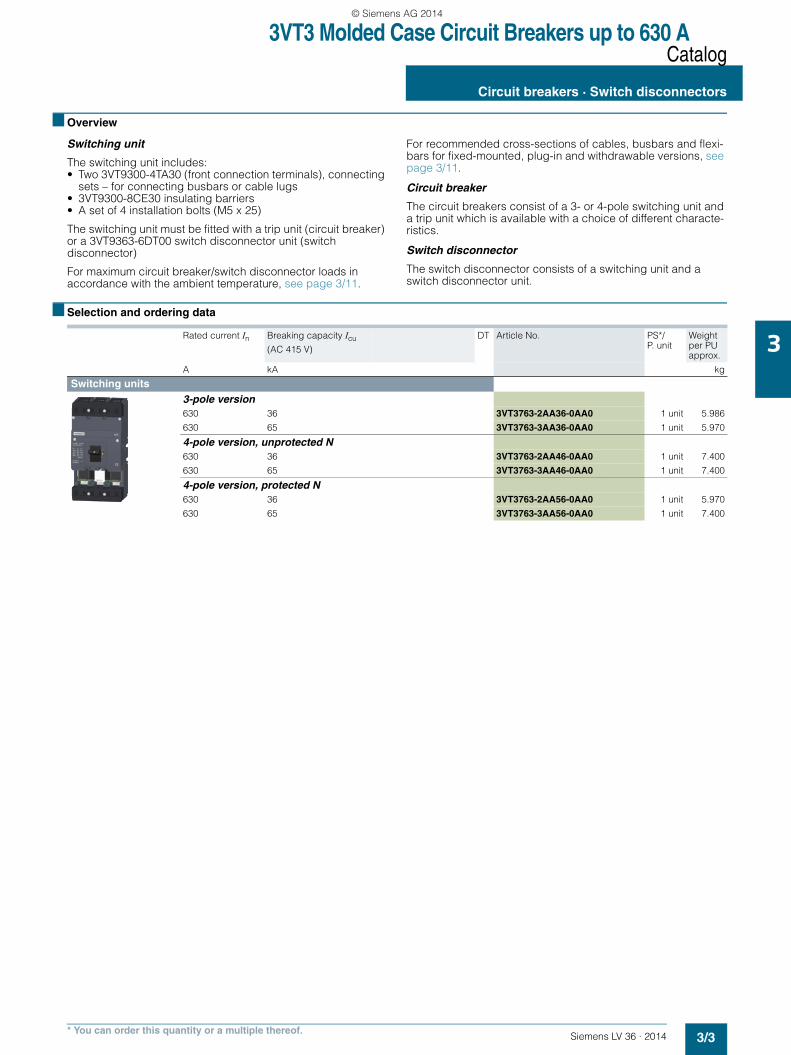
Switching unit
The switching unit includes:• Two 3VT9300-4TA30 (front connection terminals), connecting
sets – for connecting busbars or cable lugs• 3VT9300-8CE30 insulating barriers• A set of 4 installation bolts (M5 x 25)
The switching unit must be fitted with a trip unit (circuit breaker) or a 3VT9363-6DT00 switch disconnector unit (switch disconnector)
For maximum circuit breaker/switch disconnector loads in accordance with the ambient temperature, see page 3/11.
For recommended cross-sections of cables, busbars and flexi-bars for fixed-mounted, plug-in and withdrawable versions, see page 3/11.
Circuit breaker
The circuit breakers consist of a 3- or 4-pole switching unit and a trip unit which is available with a choice of different characte-ristics.
Switch disconnector
The switch disconnector consists of a switching unit and a switch disconnector unit.
■ Selection and ordering data
Rated current In Breaking capacity Icu
(AC 415 V)
DT Article No. PS*/ P. unit
Weight per PU approx.
A kA kg
Switching units
3-pole version630 36 3VT3763-2AA36-0AA0 1 unit 5.986
630 65 3VT3763-3AA36-0AA0 1 unit 5.970
4-pole version, unprotected N630 36 3VT3763-2AA46-0AA0 1 unit 7.400
630 65 3VT3763-3AA46-0AA0 1 unit 7.400
4-pole version, protected N630 36 3VT3763-2AA56-0AA0 1 unit 5.970
630 65 3VT3763-3AA56-0AA0 1 unit 7.400
LV36_2014.book Seite 3 Freitag, 31. Januar 2014 4:36 16
© Siemens AG 2014
3VT3 Molded Case Circuit Breakers up to 630 ACatalog - Accessories and Components
Circuit breakers · Switch disconnectors
3/4 Siemens LV 36 · 2014* You can order this quantity or a multiple thereof.
3
■ Selection and ordering data for accessories
1) Use only with switching unit 3VT3763-.AA36-0AA0 or 3VT3763-.AA46-0AA0.
2) Use only with switching unit 3VT3763-.AA56-0AA0
Rated current In
Current setting of the inverse- time delayed overcurrent releases "L" Ir
S function short-circuit protec-tion (short-time delayed) "S" Isd
Operating current of the instantane-ous short-circuit releases "I" Ii
DT Article No. PS*/ P. unit
Weight per PU approx.
A A kg
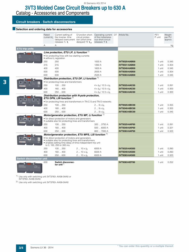
ETU trip units Line protection, ETU LP, LI function 1)
• for protecting lines with low starting currents• without Ir regulation
250 250 1000 A 3VT9325-6AB00 1 unit 0.345
315 315 1260 A 3VT9331-6AB00 1 unit 0.304
400 400 1600 A 3VT9340-6AB00 1 unit 0.345
500 500 2000 A 3VT9350-6AB00 1 unit 0.304
630 630 2520 A 3VT9363-6AB00 1 unit 0.345
Distribution protection, ETU DP, LI function 1)
• for protecting lines and transformers
250 100 ... 250 4 x IR / 12.5 x IR 3VT9325-6AC00 1 unit 0.261
400 160 ... 400 4 x IR / 12.5 x IR 3VT9340-6AC00 1 unit 0.300
630 250 ... 630 4 x IR / 12.5 x IR 3VT9363-6AC00 1 unit 0.300
Distribution protection with N-pole protection, ETU DPN, LIN function 2)
• for protecting lines and transformers in TN-C-S and TN-S networks
250 100 ... 250 2 ... 9 x IR 3VT9325-6BC00 1 unit 0.355
400 160 ... 400 2 ... 9 x IR 3VT9340-6BC00 1 unit 0.355
630 250 ... 630 2 ... 9 x IR 3VT9363-6BC00 1 unit 0.345
Motor/generator protection, ETU MP, LI function 1)
• for direct protection of motors and generators• suitable also for protecting lines and transformers
250 100 ... 250 320 ... 3750 A 3VT9325-6AP00 1 unit 0.261
400 160 ... 400 500 ... 6000 A 3VT9340-6AP00 1 unit 0.321
630 250 ... 630 800 ... 7000 A 3VT9363-6AP00 1 unit 0.323
Motor/generator protection, ETU MPS, LSI function 1)
• for direct protection of motors and generators.• suitable also for protecting lines and transformers• enables setting time delay of time-independent trip unit
to 0, 100, 200 or 300 ms
250 100 ... 250 2 ... 10 x IR 6500 A 3VT9325-6AS00 1 unit 0.260
400 160 ... 400 2 ... 10 x IR 6500 A 3VT9340-6AS00 1 unit 0.260
630 250 ... 630 2 ... 10 x IR 6500 A 3VT9363-6AS00 1 unit 0.323
Switch disconnector unit630 Switch disconnec-
tor unit1)3VT9363-6DT00 1 unit 0.252
LV36_2014.book Seite 4 Freitag, 31. Januar 2014 4:36 16
© Siemens AG 2014
3VT3 Molded Case Circuit Breakers up to 630 ACatalog - Accessories and Components
Auxiliary switches · Auxiliary trip units
3/5Siemens LV 36 · 2014* You can order this quantity or a multiple thereof.
3
■ Overview
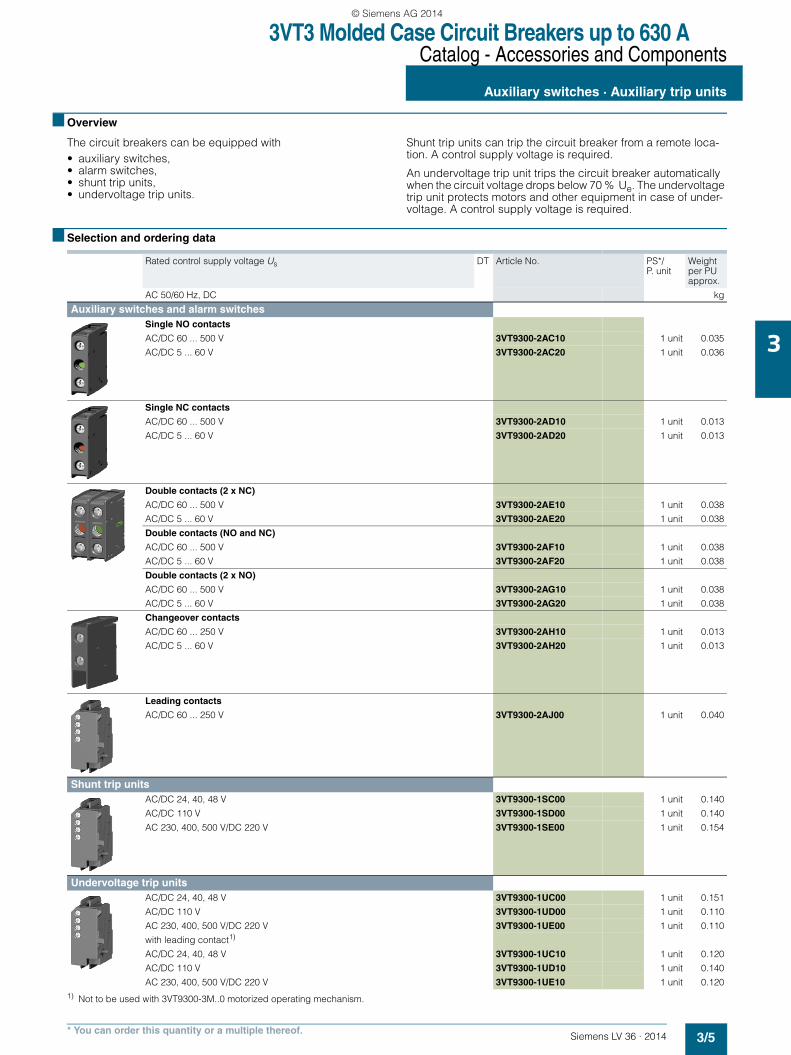
The circuit breakers can be equipped with• auxiliary switches,• alarm switches,• shunt trip units,• undervoltage trip units.
Shunt trip units can trip the circuit breaker from a remote loca-tion. A control supply voltage is required.
An undervoltage trip unit trips the circuit breaker automatically when the circuit voltage drops below 70 % Ue. The undervoltage trip unit protects motors and other equipment in case of under-voltage. A control supply voltage is required.
■ Selection and ordering data
1) Not to be used with 3VT9300-3M..0 motorized operating mechanism.
Rated control supply voltage Us DT Article No. PS*/ P. unit
Weight per PU approx.
AC 50/60 Hz, DC kg
Auxiliary switches and alarm switches Single NO contacts
AC/DC 60 ... 500 V 3VT9300-2AC10 1 unit 0.035
AC/DC 5 ... 60 V 3VT9300-2AC20 1 unit 0.036
Single NC contacts
AC/DC 60 ... 500 V 3VT9300-2AD10 1 unit 0.013
AC/DC 5 ... 60 V 3VT9300-2AD20 1 unit 0.013
Double contacts (2 x NC)
AC/DC 60 ... 500 V 3VT9300-2AE10 1 unit 0.038
AC/DC 5 ... 60 V 3VT9300-2AE20 1 unit 0.038
Double contacts (NO and NC)
AC/DC 60 ... 500 V 3VT9300-2AF10 1 unit 0.038
AC/DC 5 ... 60 V 3VT9300-2AF20 1 unit 0.038
Double contacts (2 x NO)
AC/DC 60 ... 500 V 3VT9300-2AG10 1 unit 0.038
AC/DC 5 ... 60 V 3VT9300-2AG20 1 unit 0.038
Changeover contacts
AC/DC 60 ... 250 V 3VT9300-2AH10 1 unit 0.013
AC/DC 5 ... 60 V 3VT9300-2AH20 1 unit 0.013
Leading contacts
AC/DC 60 ... 250 V 3VT9300-2AJ00 1 unit 0.040
Shunt trip units AC/DC 24, 40, 48 V 3VT9300-1SC00 1 unit 0.140
AC/DC 110 V 3VT9300-1SD00 1 unit 0.140
AC 230, 400, 500 V/DC 220 V 3VT9300-1SE00 1 unit 0.154
Undervoltage trip units AC/DC 24, 40, 48 V 3VT9300-1UC00 1 unit 0.151
AC/DC 110 V 3VT9300-1UD00 1 unit 0.110
AC 230, 400, 500 V/DC 220 V 3VT9300-1UE00 1 unit 0.110
with leading contact1)
AC/DC 24, 40, 48 V 3VT9300-1UC10 1 unit 0.120
AC/DC 110 V 3VT9300-1UD10 1 unit 0.140
AC 230, 400, 500 V/DC 220 V 3VT9300-1UE10 1 unit 0.120
LV36_2014.book Seite 5 Freitag, 31. Januar 2014 4:36 16
© Siemens AG 2014
3VT3 Molded Case Circuit Breakers up to 630 ACatalog - Accessories and Components
Manual/motorized operating mechanisms
3/6 Siemens LV 36 · 2014* You can order this quantity or a multiple thereof.
3
■ Overview
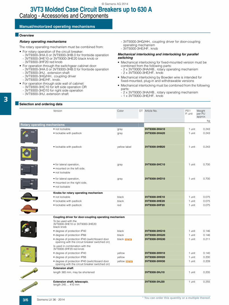
Rotary operating mechanisms
The rotary operating mechanism must be combined from:• For rotary operation of the circuit breaker:
- 3VT9300-3HA.0 or 3VT9300-3HB.0 for frontside operation - 3VT9300-3HE10 or 3VT9300-3HE20 black knob or- 3VT9300-3HF20 red knob
• For operation through the switchgear cabinet door:- 3VT9300-3HA.0 or 3VT9300-3HB.0 for frontside operation - 3VT9300-3HJ.. extension shaft- 3VT9300-3HG/HH.. coupling driver- 3VT9300-3HE/HF.. knob.
• For operation through side wall of cabinet:- 3VT9300-3HC10 for left side operation OR- 3VT9300-3HD10 for right side operation- 3VT9300-3HJ..extension shaft
- 3VT9300-3HG/HH.. coupling driver for door-coupling operating mechanism
- 3VT9300-3HE/HF.. knob
Mechanical interlocking and interlocking for parallel switching • Mechanical interlocking for fixed-mounted version must be
combined from the following parts:- 2 x 3VT9300-3HA/HB.. rotary operating mechanism- 2 x 3VT9300-3HE/HF.. knob
• Mechanical interlocking by Bowden wire is intended for fixed-mounted, plug-in and withdrawable versions
• Mechanical interlocking must be combined from the following parts:- 2 x 3VT9300-3HA/HB.. rotary operating mechanism- 1 x 3VT9300-3HE/HF.. knob
■ Selection and ordering data
Version Color DT Article No. PS*/ P. unit
Weight per PUapprox.
kg
Rotary operating mechanisms• not lockable gray 3VT9300-3HA10 1 unit 0.243
• lockable with padlock gray 3VT9300-3HA20 1 unit 0.243
• lockable with padlock yellow label 3VT9300-3HB20 1 unit 0.243
• for lateral operation,
• mounted on the left side,
• not lockable
gray 3VT9300-3HC10 1 unit 0.700
• for lateral operation,
• mounted on the right side,
• not lockable
gray 3VT9300-3HD10 1 unit 0.700
Knobs for rotary operating mechanism
• not lockable black 3VT9300-3HE10 1 unit 0.075
• lockable with padlock black 3VT9300-3HE20 1 unit 0.075
• lockable with padlock red 3VT9300-3HF20 1 unit 0.075
Coupling driver for door-coupling operating mechanism
To be used with the 3VT9300-3HE10 or 3VT9300-3HE20 black knob
• degree of protection IP40 black 3VT9300-3HG10 1 unit 0.146
• degree of protection IP66 black 3VT9300-3HG20 1 unit 0.146
• degree of protection IP40 (switchboard door opening with the circuit breaker switched on)
black 3VT9300-3HG30 1 unit 0.211
Is used in combination with the 3VT9300-3HF20 red knob
• degree of protection IP40 yellow 3VT9300-3HH10 1 unit 0.140
• degree of protection IP66 yellow 3VT9300-3HH20 1 unit 0.200
• degree of protection IP40 (switchboard door opening with the circuit breaker switched on)
yellow 3VT9300-3HH30 1 unit 0.209
Extension shaft
length 365 mm, may be shortened 3VT9300-3HJ10 1 unit 0.205
Extension shaft, telescopic, length 245 ... 410 mm
3VT9300-3HJ20 1 unit 0.255
LV36_2014.book Seite 6 Freitag, 31. Januar 2014 4:36 16
© Siemens AG 2014
3VT3 Molded Case Circuit Breakers up to 630 ACatalog - Accessories and Components
Manual/motorized operating mechanisms
3/7Siemens LV 36 · 2014* You can order this quantity or a multiple thereof.
3
Version DT Article No. PS*/ P. unit
Weight per PUapprox.
kg
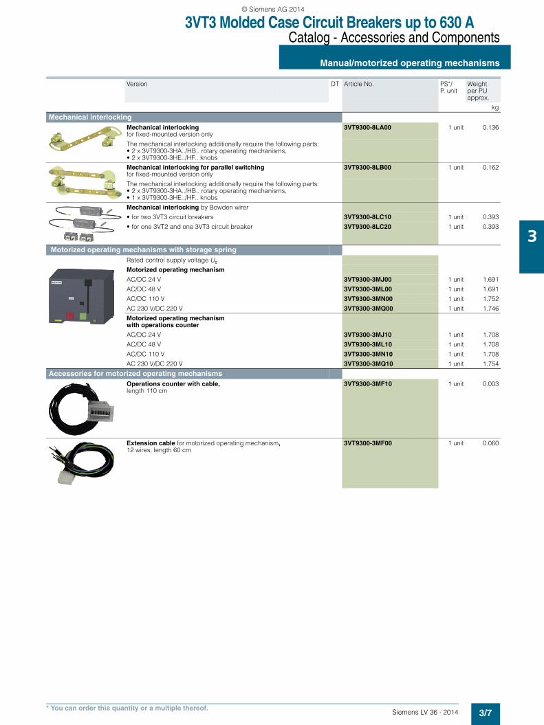
Mechanical interlockingMechanical interlocking for fixed-mounted version only
3VT9300-8LA00 1 unit 0.136
The mechanical interlocking additionally require the following parts:• 2 x 3VT9300-3HA../HB.. rotary operating mechanisms,• 2 x 3VT9300-3HE../HF.. knobs
Mechanical interlocking for parallel switching for fixed-mounted version only
3VT9300-8LB00 1 unit 0.162
The mechanical interlocking additionally require the following parts:• 2 x 3VT9300-3HA../HB.. rotary operating mechanisms,• 1 x 3VT9300-3HE../HF.. knobs
Mechanical interlocking by Bowden wirer
• for two 3VT3 circuit breakers 3VT9300-8LC10 1 unit 0.393
• for one 3VT2 and one 3VT3 circuit breaker 3VT9300-8LC20 1 unit 0.393
Motorized operating mechanisms with storage springRated control supply voltage Us
Motorized operating mechanism
AC/DC 24 V 3VT9300-3MJ00 1 unit 1.691
AC/DC 48 V 3VT9300-3ML00 1 unit 1.691
AC/DC 110 V 3VT9300-3MN00 1 unit 1.752
AC 230 V/DC 220 V 3VT9300-3MQ00 1 unit 1.746
Motorized operating mechanism with operations counter
AC/DC 24 V 3VT9300-3MJ10 1 unit 1.708
AC/DC 48 V 3VT9300-3ML10 1 unit 1.708
AC/DC 110 V 3VT9300-3MN10 1 unit 1.708
AC 230 V/DC 220 V 3VT9300-3MQ10 1 unit 1.754
Accessories for motorized operating mechanismsOperations counter with cable, length 110 cm
3VT9300-3MF10 1 unit 0.003
Extension cable for motorized operating mechanism, 12 wires, length 60 cm
3VT9300-3MF00 1 unit 0.060
LV36_2014.book Seite 7 Freitag, 31. Januar 2014 4:36 16
© Siemens AG 2014
3VT3 Molded Case Circuit Breakers up to 630 ACatalog - Accessories and Components
Mounting accessories
3/8 Siemens LV 36 · 2014* You can order this quantity or a multiple thereof.
3
■ Overview
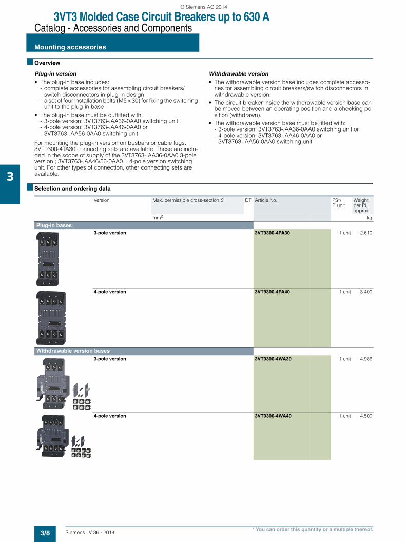
Plug-in version • The plug-in base includes:
- complete accessories for assembling circuit breakers/ switch disconnectors in plug-in design
- a set of four installation bolts (M5 x 30) for fixing the switching unit to the plug-in base
• The plug-in base must be outfitted with:- 3-pole version: 3VT3763-.AA36-0AA0 switching unit- 4-pole version: 3VT3763-.AA46-0AA0 or
3VT3763-.AA56-0AA0 switching unit
For mounting the plug-in version on busbars or cable lugs, 3VT9300-4TA30 connecting sets are available. These are inclu-ded in the scope of supply of the 3VT3763-.AA36-0AA0 3-pole version ; 3VT3763-.AA46/56-0AA0... 4-pole version switching unit. For other types of connection, other connecting sets are available.
Withdrawable version • The withdrawable version base includes complete accesso-
ries for assembling circuit breakers/switch disconnectors in withdrawable version.
• The circuit breaker inside the withdrawable version base can be moved between an operating position and a checking po-sition (withdrawn).
• The withdrawable version base must be fitted with:- 3-pole version: 3VT3763-.AA36-0AA0 switching unit or- 4-pole version: 3VT3763-.AA46-0AA0 or
3VT3763-.AA56-0AA0 switching unit
■ Selection and ordering data
Version Max. permissible cross-section S DT Article No. PS*/ P. unit
Weight per PU approx.
mm2 kg
Plug-in bases3-pole version 3VT9300-4PA30 1 unit 2.610
4-pole version 3VT9300-4PA40 1 unit 3.400
Withdrawable version bases3-pole version 3VT9300-4WA30 1 unit 4.986
4-pole version 3VT9300-4WA40 1 unit 4.500
LV36_2014.book Seite 8 Freitag, 31. Januar 2014 4:36 16
© Siemens AG 2014

3VT3 Molded Case Circuit Breakers up to 630 ACatalog - Accessories and Components
Connecting accessories
3/9Siemens LV 36 · 2014* You can order this quantity or a multiple thereof.
3
■ Selection and ordering data
Version Max. permissible cross-section S
Type of connection DT Article No. PS*/ P. unit
Weight per PU approx.
mm2 kg
Connecting SetsConnecting sets for 3-pole versionBox terminals 35 ... 240 Cu Cables,
flexibars3VT9300-4TC30 1 unit 0.440
Terminals for circular conductors
25 ... 150 Cu/Al cables 3VT9315-4TD30 1 unit 0.302
150 ... 240 Cu/Al cables 3VT9324-4TD30 1 unit 0.300
For enhancing termination point protection to degree of protection IP20, use the 3VT9300-8CB30 terminal cover
2 x 25 ... 150 Cu/Al cables 3VT9315-4TF30 1 unit 0.900
2 x 150 ... 240 Cu/Al cables 3VT9324-4TF30 1 unit 0.721
6 x 6 ... 35 Cu/Al cables 3VT9303-4TF30 1 unit 0.300
Terminals for rear connec-tion
1 set = 3 units
Cu/Al busbars cable lugs
3VT9300-4RC30 1 unit 0.558
Terminals for front connec-tion
1 set = 3 units
Cu/Al busbars, cable lugs, flexibars
3VT9300-4TA30 1 unit 0.186
Auxiliary conductor termi-nals
1.5 ... 2.5; 4 ... 6 Cu flexible conductors
3VT9300-4TN30 1 unit 0.021
Front connection bars
1 set = 3 units increases pole spacing
Cu/Al busbars cable lugs, flexibars
3VT9300-4ED30 1 unit 0.489
1 set = 3 units increases pole spacing
Cu/Al busbars cable lugs, flexibars
3VT9300-4EE30 1 unit 0.656
Single terminals for 3- or 4-pole versionBox terminal
1 set = 1 unit
35 ... 240 Cu Cables, flexibars
3VT9300-4TC00 1 unit 0.580
Terminals for circular con-ductors
1 set = 1 unit
25 ... 150 Cu/Al cables 3VT9315-4TD00 1 unit 0.126
150 ... 240 Cu/Al cables 3VT9324-4TD00 1 unit 0.110
2 x 25 ... 150 Cu/Al cables 3VT9315-4TF00 1 unit 0.285
2 x 150 ... 240 Cu/Al cables 3VT9324-4TF00 1 unit 0.285
6 x 6 ... 35 Cu/Al cables 3VT9303-4TF00 1 unit 0.100
Terminal for rear connection
1 set = 1 unit
Cu/Al busbars cable lugs
3VT9300-4RC00 1 unit 0.200
LV36_2014.book Seite 9 Freitag, 31. Januar 2014 4:36 16
© Siemens AG 2014
3VT3 Molded Case Circuit Breakers up to 630 ACatalog - Accessories and Components
Further accessories
3/10 Siemens LV 36 · 2014* You can order this quantity or a multiple thereof.
3
■ Selection and ordering data
Version DT Article No. PS*/ P. unit
Weight per PU approx.
kg
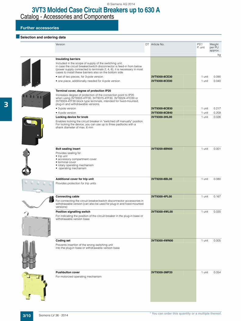
Insulating barriers
Included in the scope of supply of the switching unit; in case the circuit breaker/switch disconnector is feed-in from below (power supply connected to terminals 2, 4, 6), it is necessary in most cases to install these barriers also on the bottom side
• set of two pieces, for 3-pole version 3VT9300-8CE30 1 unit 0.090
• one piece, additionally needed for 4-pole version 3VT9300-8CE00 1 unit 0.040
Terminal cover, degree of protection IP20
Increases degree of protection of the connection point to IP20 when using 3VT9303-4TF30, 3VT9315-4TF30, 3VT9324-4TD30 or 3VT9324-4TF30 block type terminals, intended for fixed-mounted, plug-in and withdrawable versions.
• 3-pole version 3VT9300-8CB30 1 unit 0.217
• 4-pole version 3VT9300-8CB40 1 unit 0.209
Locking device for knob 3VT9300-3HL00 1 unit 0.026
Enables locking the circuit breaker in "switched off manually" position. For locking the device, you can use up to three padlocks with a shank diameter of max. 6 mm
Bolt sealing insert 3VT9200-8BN00 1 unit 0.001
Provides sealing for:• trip unit• accessory compartment cover• terminal cover• rotary operating mechanism• operating mechanism
Additional cover for trip unit 3VT9200-8BL00 1 unit 0.080
Provides protection for trip units
Connecting cable 3VT9300-4PL00 1 unit 0.167
For connecting the circuit breaker/switch disconnector accessories in withdrawable version (can also be used for plug-in and fixed-mounted versions)
Position signalling switch 3VT9300-4WL00 1 unit 0.020
For indicating the position of the circuit breaker in the plug-in base or withdrawable version base
Coding set 3VT9300-4WN00 1 unit 0.005
Prevents insertion of the wrong switching unit into the plug-in base or withdrawable version base
Pushbutton cover 3VT9300-3MF20 1 unit 0.054
For motorized operating mechanism
LV36_2014.book Seite 10 Freitag, 31. Januar 2014 4:36 16
© Siemens AG 2014
3VT3 Molded Case Circuit Breakers up to 630 ATechnical Information
Circuit breakers · Switch disconnectors
3/11Siemens LV 36 · 2014
3
■ Design
Installation and connection
Main circuit• Is connected using Cu or Al busbars or cables, and possibly
cables with cable lugs• For further connecting options, connecting sets are available
(see page 3/9)• Generally, conductors from the power supply are connected
to input terminals 1, 3, 5, (N) and conductors from the load to terminals 2, 4, 6, (N). However, it is possible to reverse this connection (exchanging input and output terminals without limiting the rated short-circuit ultimate breaking capacity Icu)
• In case of feed-in from below, the circuit breakers/switch dis-connectors must be fitted with 3VT9300-8CE30 insulating bar-riers on the bottom side of the circuit breaker/switch discon-nector
• We recommend painting the connecting busbars in different colors
• Input and output conductors/busbars must be mechanically reinforced to avoid transmitting electrodynamic force to the circuit breaker/switch disconnector during short-circuiting
• The power circuit must be connected in such a way that the deionizing space of the circuit breaker/switch disconnector is not obstructed (see page 3/45).
Auxiliary circuits• Auxiliary switches, shunt trip units or undervoltage trip units
are connected to terminals using flexible 0.5 ... 1 mm2 Cu conductors.
• The motorized operating mechanism and auxiliary circuits of the plug-in base or withdrawable version base are connected with a connector.
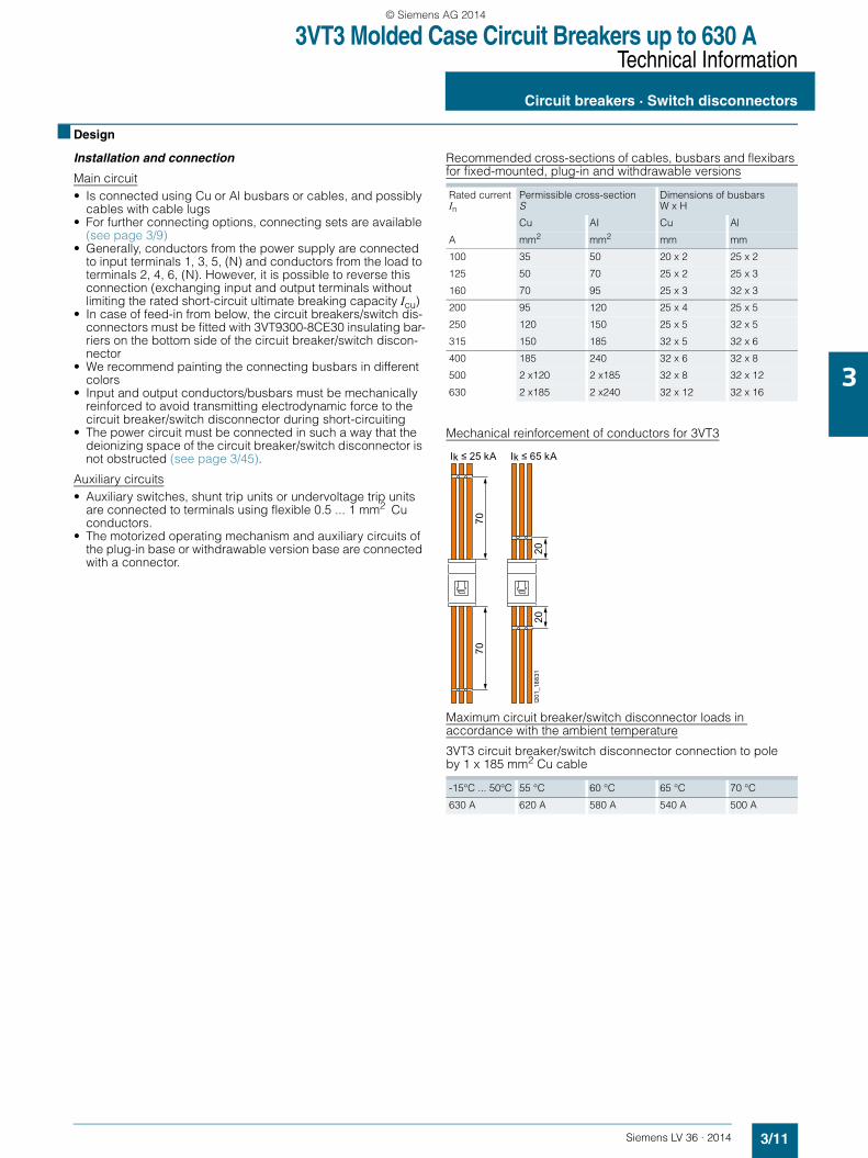
Recommended cross-sections of cables, busbars and flexibars for fixed-mounted, plug-in and withdrawable versions
Mechanical reinforcement of conductors for 3VT3
Maximum circuit breaker/switch disconnector loads in accordance with the ambient temperature
3VT3 circuit breaker/switch disconnector connection to pole by 1 x 185 mm2 Cu cable
Rated current In
Permissible cross-section S
Dimensions of busbars W x H
Cu AI Cu Al
A mm2 mm2 mm mm
100 35 50 20 x 2 25 x 2
125 50 70 25 x 2 25 x 3
160 70 95 25 x 3 32 x 3
200 95 120 25 x 4 25 x 5
250 120 150 25 x 5 32 x 5
315 150 185 32 x 5 32 x 6
400 185 240 32 x 6 32 x 8
500 2 x120 2 x185 32 x 8 32 x 12
630 2 x185 2 x240 32 x 12 32 x 16
-15°C ... 50°C 55 °C 60 °C 65 °C 70 °C
630 A 620 A 580 A 540 A 500 A
7070
2020
Ik ≤ 25 kA Ik ≤ 65 kA
I201
_188
31
LV36_2014.book Seite 11 Freitag, 31. Januar 2014 4:36 16
© Siemens AG 2014
3VT3 Molded Case Circuit Breakers up to 630 ATechnical Information
Circuit breakers · Switch disconnectors
3/12 Siemens LV 36 · 2014
3
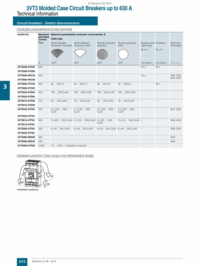
Conductor cross-sections of main terminals
Installation positions: fixed, plug-in and withdrawable design
Article No. Maximum permitted current Imax
Maximum permissible conductor cross-section S
Cable type
Sector-shaped conductor, stranded
Sector-shaped conductor, solid
Round conductor, stranded
Round conductor, solid
Busbars and cable lugs
Flexibars Technical information
W x H W x H
A mm2 mm2 mm2 mm2 mm (max.) mm (max.) See page
3VT9300-4TA30 630 32 x... 32 x...
3VT9300-4TD00
3VT9300-4RC30 630 32 x... -- 3/48, 3/59, 3/59, 3/59
3VT9300-4RC00
3VT9300-4TC30 400 35 ... 240 Cu 35 ... 240 Cu 35 ... 240 Cu 35 ... 240 Cu -- 32 x...
3VT9300-4TC00
3VT9324-4TD30 400 150 ... 240 Cu/Al 120 ... 240 Cu/Al 150 ... 240 Cu/Al 120 ... 240 Cu/Al -- --
3VT9324-4TD00
3VT9315-4TD30 315 25 ... 150 Cu/AI 16 ... 150 Cu/AI 25 ... 150 Cu/AI 16 ... 150 Cu/AI -- --
3VT9315-4TD00
3VT9324-4TF30 630 2 x (150 ... 240) Cu/Al
2 x (120 ... 240) Cu/Al
2 x (150 ... 240) Cu/Al
2 x (120 ... 240) Cu/Al
-- -- 3/47, 3/58
3VT9324-4TF00
3VT9315-4TF30 500 2 x (25 ... 150) Cu/Al 2 x (16 ... 150) Cu/Al 2 x (25 ... 150) Cu/Al
2 x (16 ... 150) Cu/Al -- -- 3/48, 3/59
3VT9315-4TF00
3VT9303-4TF30 250 6 x (6 ... 35) Cu/Al 6 x (6 ... 35) Cu/Al 6 x (6 ... 35) Cu/Al 6 x (6 ... 35) Cu/Al -- -- 3/48, 3/59
3VT9303-4TF00
3VT9300-4ED30 400 3/49
3VT9300-4EE30 630 3/49
3VT9300-4TN30 10/16 1,5 ... 2,5/4 ... 6 flexible conductor --
Installation positions
I201
_189
60
90°
90°90°
25°
LV36_2014.book Seite 12 Freitag, 31. Januar 2014 4:36 16
© Siemens AG 2014
3VT3 Molded Case Circuit Breakers up to 630 ATechnical Information
Circuit breakers · Switch disconnectors
3/13Siemens LV 36 · 2014
3
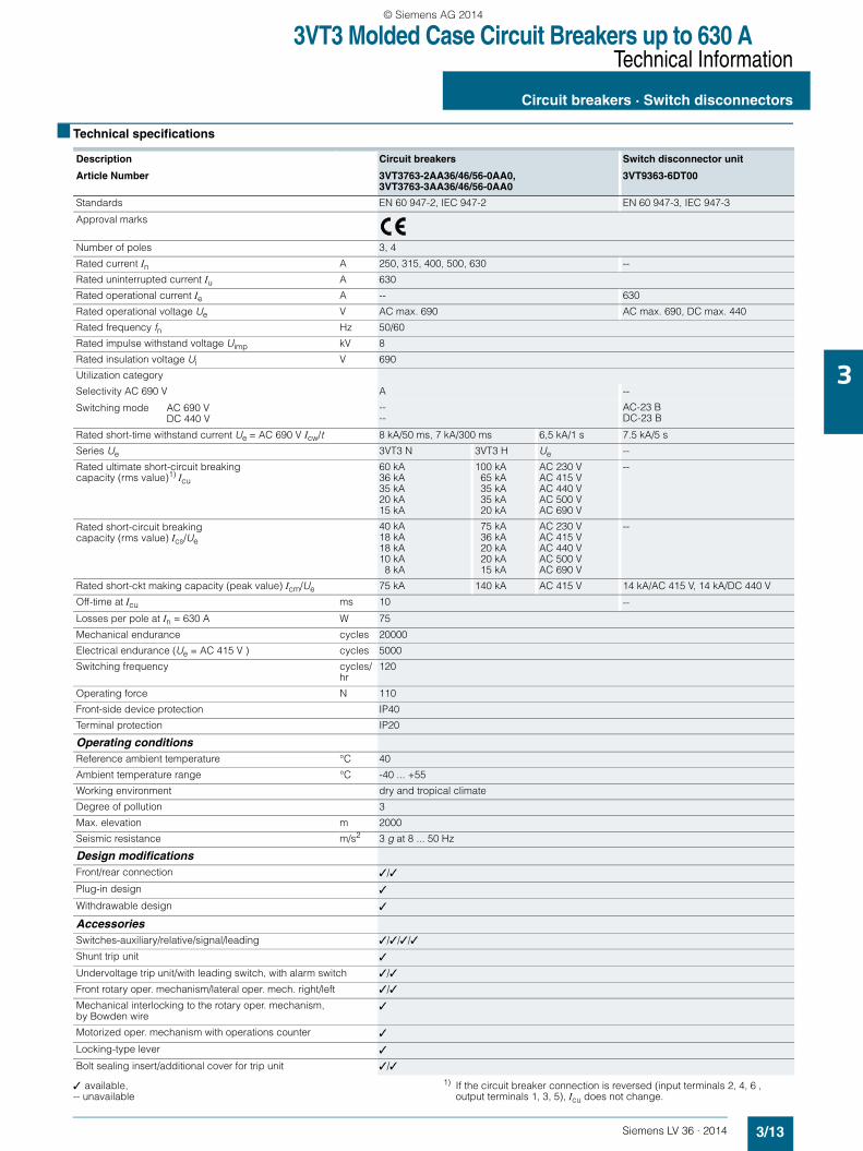
■ Technical specifications
✓ available,-- unavailable
1) If the circuit breaker connection is reversed (input terminals 2, 4, 6 ,output terminals 1, 3, 5), Icu does not change.
Description Circuit breakers Switch disconnector unit
Article Number 3VT3763-2AA36/46/56-0AA0, 3VT3763-3AA36/46/56-0AA0
3VT9363-6DT00
Standards EN 60 947-2, IEC 947-2 EN 60 947-3, IEC 947-3
Approval marks
Number of poles 3, 4
Rated current In A 250, 315, 400, 500, 630 --
Rated uninterrupted current Iu A 630
Rated operational current Ie A -- 630
Rated operational voltage Ue V AC max. 690 AC max. 690, DC max. 440
Rated frequency fn Hz 50/60
Rated impulse withstand voltage Uimp kV 8
Rated insulation voltage Ui V 690
Utilization category
Selectivity AC 690 V A --
Switching mode AC 690 VDC 440 V
----
AC-23 BDC-23 B
Rated short-time withstand current Ue = AC 690 V Icw/t 8 kA/50 ms, 7 kA/300 ms 6,5 kA/1 s 7.5 kA/5 s
Series Ue 3VT3 N 3VT3 H Ue --
Rated ultimate short-circuit breaking capacity (rms value)1) Icu
60 kA36 kA 35 kA20 kA 15 kA
100 kA65 kA35 kA35 kA20 kA
AC 230 VAC 415 VAC 440 VAC 500 V AC 690 V
--
Rated short-circuit breaking capacity (rms value) Ics/Ue
40 kA 18 kA 18 kA10 kA
8 kA
75 kA36 kA20 kA20 kA15 kA
AC 230 VAC 415 VAC 440 VAC 500 VAC 690 V
--
Rated short-ckt making capacity (peak value) Icm/Ue 75 kA 140 kA AC 415 V 14 kA/AC 415 V, 14 kA/DC 440 V
Off-time at Icu ms 10 --
Losses per pole at In = 630 A W 75
Mechanical endurance cycles 20000
Electrical endurance (Ue = AC 415 V ) cycles 5000
Switching frequency cycles/hr
120
Operating force N 110
Front-side device protection IP40
Terminal protection IP20
Operating conditionsReference ambient temperature °C 40
Ambient temperature range °C -40 ... +55
Working environment dry and tropical climate
Degree of pollution 3
Max. elevation m 2000
Seismic resistance m/s2 3 g at 8 ... 50 Hz
Design modificationsFront/rear connection ✓/✓
Plug-in design ✓
Withdrawable design ✓
AccessoriesSwitches-auxiliary/relative/signal/leading ✓/✓/✓/✓
Shunt trip unit ✓
Undervoltage trip unit/with leading switch, with alarm switch ✓/✓
Front rotary oper. mechanism/lateral oper. mech. right/left ✓/✓
Mechanical interlocking to the rotary oper. mechanism, by Bowden wire
✓
Motorized oper. mechanism with operations counter ✓
Locking-type lever ✓
Bolt sealing insert/additional cover for trip unit ✓/✓
LV36_2014.book Seite 13 Freitag, 31. Januar 2014 4:36 16
© Siemens AG 2014

3VT3 Molded Case Circuit Breakers up to 630 ATechnical Information
Circuit breakers · Switch disconnectors
3/14 Siemens LV 36 · 2014
3
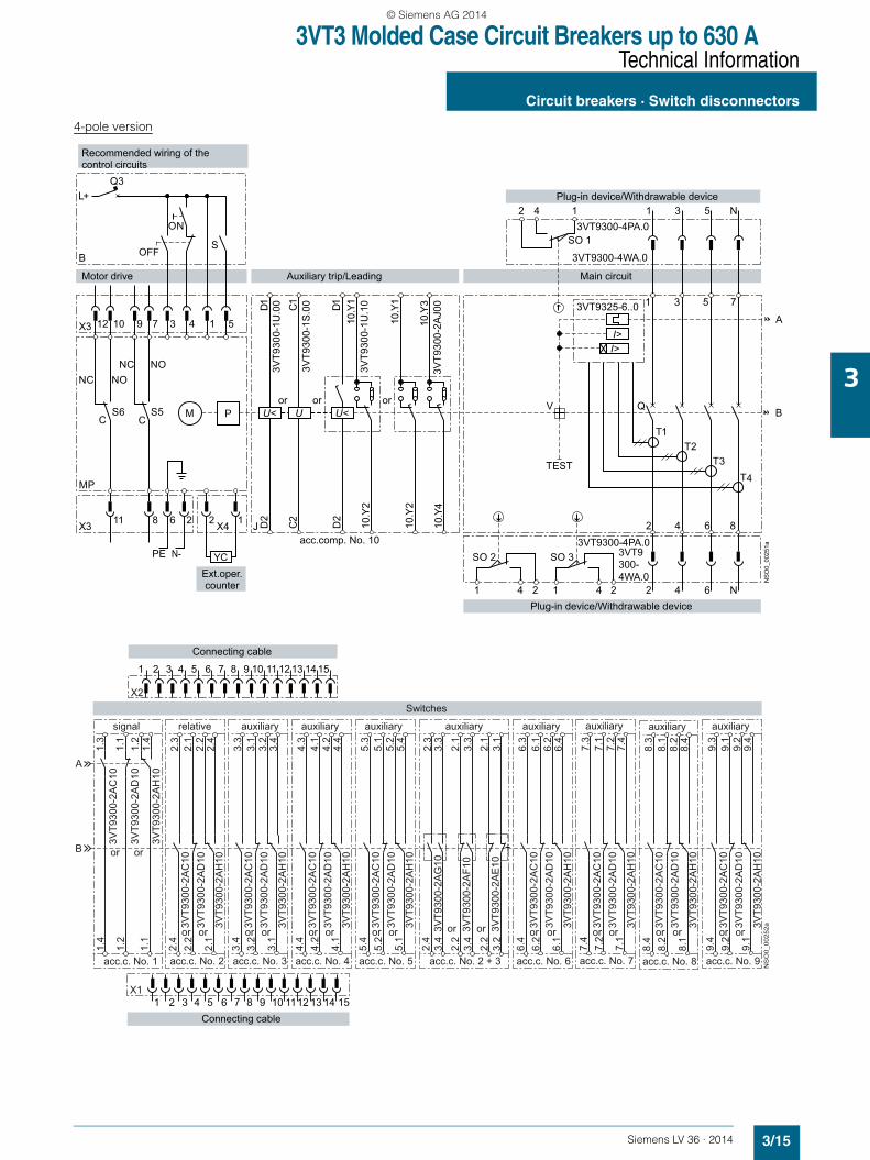
■ Schematics
Circuit breakers with accessories
3-pole version
L+Q3
JX4 D2
D2
10.Y
210
.Y1
10.Y
1
10.Y
310
.Y2
10.Y
4
C2
D1 D1C1
YC
3
6
4
2
1
2
5
1
13VT9325-6..00
SO 3
SO 1
T3T2
T1
V QB
A
SO 2
1 4 2 1 4 2
2 4
3 5
X3
MP
S6C
X3
12 10
11
M P U< U<
I>I>
U
6
2 4
2 4
6
2 4 1 1 3 5
TEST
NS
O0_
0024
9a
3VT9300-4PA.0
3VT9300-4WA.0
3VT9
300-
1U.0
0
3VT9
300-
1S.0
0
3VT9
300-
1U.1
0
3VT9
300-
2AJ0
0
SB
PE N-
S5C
9 7
8
3VT9
300-
1U.1
0
3VT9300-4PA.03VT9 300-4WA.0
Recommended wiring of thecontrol circuits
Ext.oper.counter
acc.comp. No. 10
Plug-in device/Withdrawable device
Plug-in device/Withdrawable device
Main circuit
ON
OFF
Motor drive Auxiliary trip/Leading
or or or
NC NO
NC NO
X2
1 2 3 4 5 6 7 8 9 10 11 12 13 14 15
2.3
2.1
2.2
2.4
3.3
3.1
3.2
3.4
2.3
3.3
2.1
3.3
2.1
3.1
4.3
4.1
4.2
4.4
5.3
5.1
5.2
5.4
A
B
1.3
1.1
1.2
1.4
3VT9
300-
2AC
10
3VT9
300-
2AD
10
3VT9
300-
2AH
10
1.4
1.2
1.1
2.4
2.2
2.1
3.4
3.2
3.1
2.4
3.4
2.2
3.4
2.2
3.2
4.4
4.2
4.1
5.4
5.2
5.1
X11 2 3 4 5 6 7 8 9 10 1112 13 14 15
3VT9
300-
2AG
10
3VT9
300-
2AF1
0
3VT9
300-
2AE
10
NS
O0_
0025
0a
Connecting cable
relative auxiliarysignal auxiliaryauxiliary auxiliary
acc.c. No. 2 acc.c. No. 3 acc.c. No. 2 + 3acc.c. No. 4 acc.c. No. 5acc.c. No. 1
or or
or or or or or or ororor oror
3VT9
300-
2AC
10
3VT9
300-
2AD
10
3VT9
300-
2AH
10
3VT9
300-
2AC
10
3VT9
300-
2AD
10
3VT9
300-
2AH
10
3VT9
300-
2AC
10
3VT9
300-
2AD
10
3VT9
300-
2AH
10
3VT9
300-
2AC
10
3VT9
300-
2AD
10
3VT9
300-
2AH
10
Switches
Connecting cable
LV36_2014.book Seite 14 Freitag, 31. Januar 2014 4:36 16
© Siemens AG 2014
3VT3 Molded Case Circuit Breakers up to 630 ATechnical Information
Circuit breakers · Switch disconnectors
3/15Siemens LV 36 · 2014
3
4-pole version
L+Q3
JX4 D2
D2
10.Y
210
.Y1
10.Y
1
10.Y
310
.Y2
10.Y
4
C2
D1 D1C1
YC
3
6
4
2
1
2
5
1
13VT9325-6..0
SO 3
SO 1
T3T2
T1
V QB
A
SO 2
1 4 2 1 4 2 2 4
3 5
X3
MP
S6C
X3
12 10
11
M P U< U<
I>I>
U
6
2 4 1 1 3 5
TESTT4
N
7
N
2 4 6 8
NS
O0_
0025
1a
3VT9
300-
1U.0
0
3VT9
300-
1S.0
0
3VT9
300-
1U.1
0
3VT9
300-
2AJ0
0
SB
N-
S5C
9 7
8
PE3VT9300-4PA.0
3VT9300-4PA.0
3VT9300-4WA.0
3VT9 300-4WA.0
Recommended wiring of thecontrol circuits
Ext.oper.counter
acc.comp. No. 10
Plug-in device/Withdrawable device
Plug-in device/Withdrawable device
Main circuit
ON
OFF
Motor drive Auxiliary trip/Leading
or or or
NC NONC NO
2.3
3.3
2.1
3.3
2.1
3.1
1.3
1.1
1.2
1.4
3VT9
300-
2AC
10
3VT9
300-
2AD
10
3VT9
300-
2AH
10
1.4
1.2
1.1
2.4
3.4
2.2
3.4
2.2
3.2
NS
O0_
0025
2a
5.3
5.1
5.2
5.4
5.4
5.2
5.1
4.3
4.1
4.2
4.4
4.4
4.2
4.1
2.3
2.1
2.2
2.4
2.4
2.2
2.1
3.3
3.1
3.2
3.4
3.4
3.2
3.1
7.3
7.1
7.2
7.4
7.4
7.2
7.1
8.3
8.1
8.2
8.4
8.4
8.2
8.1
9.3
9.1
9.2
9.4
9.4
9.2
9.1
6.3
6.1
6.2
6.4
6.4
6.2
6.1
A
B
3VT9
300-
2AC
103V
T930
0-2A
D10
3VT9
300-
2AH
10
3VT9
300-
2AG
10
3VT9
300-
2AF1
0
3VT9
300-
2AE
10
3VT9
300-
2AC
103V
T930
0-2A
D10
3VT9
300-
2AH
10
3VT9
300-
2AC
103V
T930
0-2A
D10
3VT9
300-
2AH
10
3VT9
300-
2AC
103V
T930
0-2A
D10
3VT9
300-
2AH
10
3VT9
300-
2AC
103V
T930
0-2A
D10
3VT9
300-
2AH
10
3VT9
300-
2AC
103V
T930
0-2A
D10
3VT9
300-
2AH
10
3VT9
300-
2AC
103V
T930
0-2A
D10
3VT9
300-
2AH
10
3VT9
300-
2AC
103V
T930
0-2A
D10
3VT9
300-
2AH
10
signal auxiliary
acc.c. No. 2 + 3acc.c. No. 1
or or
relative auxiliary
acc.c. No. 2 acc.c. No. 3 acc.c. No. 5acc.c. No. 4
auxiliaryauxiliary
or oror or oror orororor
Switches
acc.c. No. 7 acc.c. No. 8 acc.c. No. 9acc.c. No. 6
auxiliary auxiliary auxiliaryauxiliary
X2
1 2 3 4 5 6 7 8 9 10 11 12 13 14 15
Connecting cable
X11 2 3 4 5 6 7 8 9 10 1112 13 14 15
Connecting cable
oror oror orororor
LV36_2014.book Seite 15 Freitag, 31. Januar 2014 4:36 16
© Siemens AG 2014

3VT3 Molded Case Circuit Breakers up to 630 ATechnical Information
Circuit breakers · Switch disconnectors
3/16 Siemens LV 36 · 2014
3
1) Only for 4-pole version of the 3VT3763-.AA36-0AA0 switching unit.
■ Functions
States of auxiliary switches located in the switching unit accessory compartment
0 = contact open, 1 = contact closed 1) Accessory compartment 6, 7, 8, 9 are only for 4.pole design.
MP 3VT9300-3M..0 motorized operating mechanism
M Motor
P Energy storage device
X3 Connector to connect control circuits
X4 Connector for external operations counter
S5 Switch to signal AUTO (NO-C) / MANUAL (NC-C) modes
S6 Switch to signal full storage (ready to switch on: NO-C)
YC External operations counter, 3VT9300-3MF10
B Recommended wiring of the control circuits - not inclu-ded with drive
ON, OFF Pushbutton
S Switch for energy storage (switched on = automatic sto-rage, switch may be continuously switched on)
Q3 Circuit breaker for motorized operating mechanism
J 3VT3 switching unit
Q Main contacts
T1, T2, T3, T41) Current transformers
V Trip-free mechanism
3VT9325-6..00 3VT9363-6DT00 circuit breaker - trip unit - ETU LP, DP, MDP switch-disconnector - switch-disconnector unit
TEST Pushbutton to test trip unit
3VT9300-4PA.0 3-pole/-4-pole plug-in base
3VT9300-4WA.0 3-pole/-4-pole withdrawable version base
X1, X2 3VT9300-4PL00 connecting cable
SO1, SO2, SO3 Contacts signalling position of circuit breaker/switch dis-connector in plug-in base or withdrawable version base(Position signalling switch 3VT9300-4WL00)
3VT9300-1U.00 Undervoltage trip unit
3VT9300-1S.00 Shunt trip unit
3VT9300-1U.10 Undervoltage trip unit with leading contact
3VT9300-2AJ00 Leading contact
acc. c. No. Accessory compartment number
Circuit breaker state
Leve
r p
ositi
on o
f circ
uit b
reak
er
Sta
te o
f the
mai
n co
ntac
ts
Accessory compartment
1 2 3, 4, 5 (6 ... 9)1)
10 2 and 3 2 and 3 2 and 3 1 2 3, 4, 5 (6 ... 9)1)
3VT
9300
-2A
C10
3VT
9300
-2A
D10
3VT
9300
-2A
C10
3VT
9300
-2A
D10
3VT
9300
-2A
C10
3VT
9300
-2A
D10
3VT
9300
-2A
J00
or
3VT
9300
-1U
.10
3VT
9300
-2A
G10
3VT
9300
-2A
F10
3VT
9300
-2A
E10
3VT
9300
-2A
H10
3VT
9300
-2A
H10
3VT
9300
-2A
H10
Switched no 1 1 0 0 1 1 0 1 0 1 1 0 1 0 0 1 0 0 1 1 0
Switched off manually or electrically by operating mechanism
0 1 0 0 1 0 1 0 1 0 0 1 0 1 1 1 0 0 1 0 1
Switched off by trip unit 0 0 1 1 0 0 1 0 1 0 0 1 0 1 1 0 1 1 0 0 1
Switched off by auxiliary trip unit or by TEST button or the trip pushbutton on the motorized operating mechanism
0 1 0 1 0 0 1 0 1 0 0 1 0 1 1 1 0 1 0 0 1
LV36_2014.book Seite 16 Freitag, 31. Januar 2014 4:36 16
© Siemens AG 2014
3VT3 Molded Case Circuit Breakers up to 630 ATechnical Information - Accessories and Components
Trip units
3/17Siemens LV 36 · 2014
3
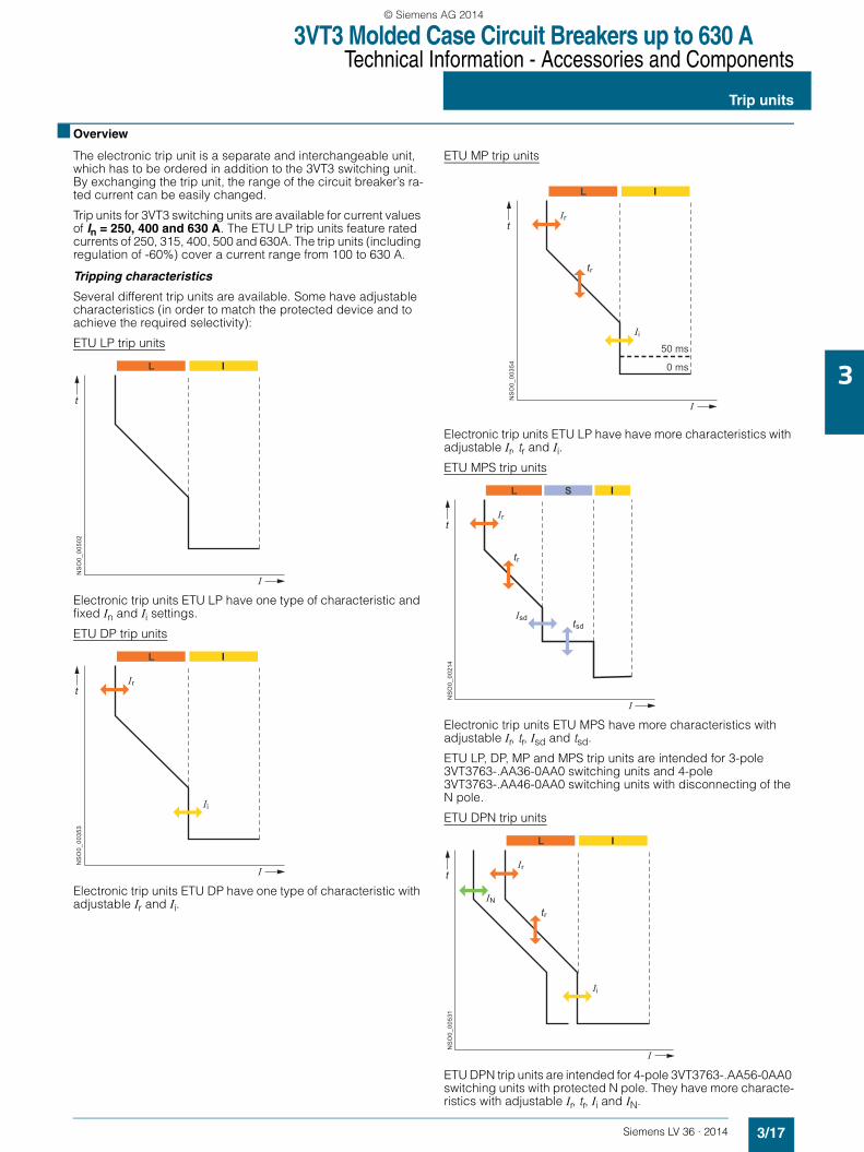
■ Overview
The electronic trip unit is a separate and interchangeable unit, which has to be ordered in addition to the 3VT3 switching unit. By exchanging the trip unit, the range of the circuit breaker’s ra-ted current can be easily changed.
Trip units for 3VT3 switching units are available for current values of In = 250, 400 and 630 A. The ETU LP trip units feature rated currents of 250, 315, 400, 500 and 630A. The trip units (including regulation of -60%) cover a current range from 100 to 630 A.
Tripping characteristics
Several different trip units are available. Some have adjustable characteristics (in order to match the protected device and to achieve the required selectivity):
ETU LP trip units
Electronic trip units ETU LP have one type of characteristic and fixed In and Ii settings.
ETU DP trip units
Electronic trip units ETU DP have one type of characteristic with adjustable Ir and Ii.
ETU MP trip units
Electronic trip units ETU LP have have more characteristics with adjustable Ir, tr and Ii.ETU MPS trip units
Electronic trip units ETU MPS have more characteristics withadjustable Ir, tr, Isd and tsd.
ETU LP, DP, MP and MPS trip units are intended for 3-pole 3VT3763-.AA36-0AA0 switching units and 4-pole 3VT3763-.AA46-0AA0 switching units with disconnecting of the N pole.
ETU DPN trip units
ETU DPN trip units are intended for 4-pole 3VT3763-.AA56-0AA0 switching units with protected N pole. They have more characte-ristics with adjustable Ir, tr, Ii and IN.
NS
O0_
0050
2
t
I
L I
NS
O0_
0035
3
t
I
L I
Ir
Ii
tr
NS
O0_
0035
4
t
I
L I
Ir
50 ms
0 ms
Ii
NS
O0_
0021
4
t
I
L S I
Ir
Isd tsd
tr
NS
O0_
0053
1
t
I
L I
Ir
tr
Ii
IN
LV36_2014.book Seite 17 Freitag, 31. Januar 2014 4:36 16
© Siemens AG 2014
3VT3 Molded Case Circuit Breakers up to 630 ATechnical Information - Accessories and Components
Trip units
3/18 Siemens LV 36 · 2014
3
Trip units ETU LP, DP, MP and MPS - description of function
Proper functioning of trip units does not depend on the current waveform in the main circuit. The function of the trip unit is supported by a microprocessor, which processes a sampled signal of the main circuit and recalculates it to obtain an rms value. Therefore, the trip units are suitable for protecting circuits where the sinusoidal current is distorted by high harmonics (e.g. circuits with controlled rectifiers, power factor compensa-tors, pulse loading, and the like).
All the trip units protect a circuit against short-circuiting and overloading. Tripping characteristic of the trip units is indepen-dent of the ambient temperature. The trip unit is attached to the switching unit by two bolts. The translucent cover over the adjustment controls can be sealed (with sealing wire).
Setting the tripping characteristics
The tripping characteristic of the trip units is defined by standard EN 60947-2. For trip units ETU DP, MP, MPS and DPN, the cha-racteristic is adjusted with latched switches located on the trip unit.
A visual demonstration on setting the tripping characteristic is available in the SIMARIS design software (Tool for Dimensioning Electrical Power Distribution).
L is a zone of low overcurrents and includes the area of thermal protection.
S is a zone of medium overcurrents and includes long-distance short-circuit protection for lines. Intentional delay in tripping of these low short-circuit currents can be used to achieve selecti-vity of protective devices. For ETU MPS trip units, the delay can be set at 0, 100, 200 or 300 ms.
I is a zone of high overcurrents and includes protection against ultimate short-circuit currents. For ETU MP trip units, the time de-lay can be set at 0 or 50 ms.
ETU MP and MPS
1. Time-dependent trip unit (thermal) L• The time-dependent trip unit ETU DP is adjusted using one Ir
switch. The Ir switch adjusts the circuit breaker’s rated current, with the characteristic shifting on the current axis. The trip unit is set to one type of characteristic.
• The time-dependent trip units ETU MP, MPS and DPN are ad-justed with two switches, Ir and tr. The first ( Ir) switch adjusts the circuit breaker’s rated current. The characteristic moves along the current axis.By turning the other switch (tr), the time is adjusted after which the circuit breaker will trip while passing through 7.2 Ir. The tripping characteristic thus moves along the time axis. Using the tr switch, it is possible to set a total of 8 characteristics. ETU MP and MPS trip units have 4 characteristics for motor protection and 4 characteristics for protecting lines. Breaking times correspond to trip unit classes 10 A, 10, 20, 30. By changing tr, it is possible to select the trip unit characteris-tic according to the required motor starting characteristic (light, medium, heavy or very heavy starting). ETU DPN trip units have 8 characteristics for protecting lines or transformers. It is not possible to turn the circuit breaker back on immediately after the time-dependent trip unit has been actuated and the circuit breaker has tripped. The trip unit must be allowed to cool off (it has a thermal memory). The thermal memory can be disabled by turning the switch from the normal "Tt" position to the "T0" position. In the "T0" position the time-dependent trip unit remains active, and only its ther-mal memory is deactivated. Switching off the thermal memory should be used only in well-justified cases, and with the knowl-edge that there could be rising temperature in the protected device, causing repeated tripping.
2. Delayed time-independent trip unit S
This trip unit characteristic is available only in ETU MPS trip units. It is used to set up a selective cascade of circuit breakers. It is set up using parameters Isd and tsd. Isd is an n-multiple of current Ir (Isd= n × Ir). Isd is a short-circuit current that, within the span of Ii to Ii, will trip the circuit breaker with delay tsd, where tsd is a delay set up for switching off the trip unit. The delayed time-independent trip unit actuates the circuit breaker if the current in the circuit reaches at least the preset n-multiple and lasts at least the preset delay time tsd.
3. Time-independent instantaneous trip unit (short-circuit trip unit) I• For trip units ETU DP, MP and MPS, the time-independent in-
stantaneous trip unit is adjusted with the Ii switch. The Ii switch is used for setting up the short-circuit current that, when reached or exceeded, causes instantaneous tripping of the circuit breaker.
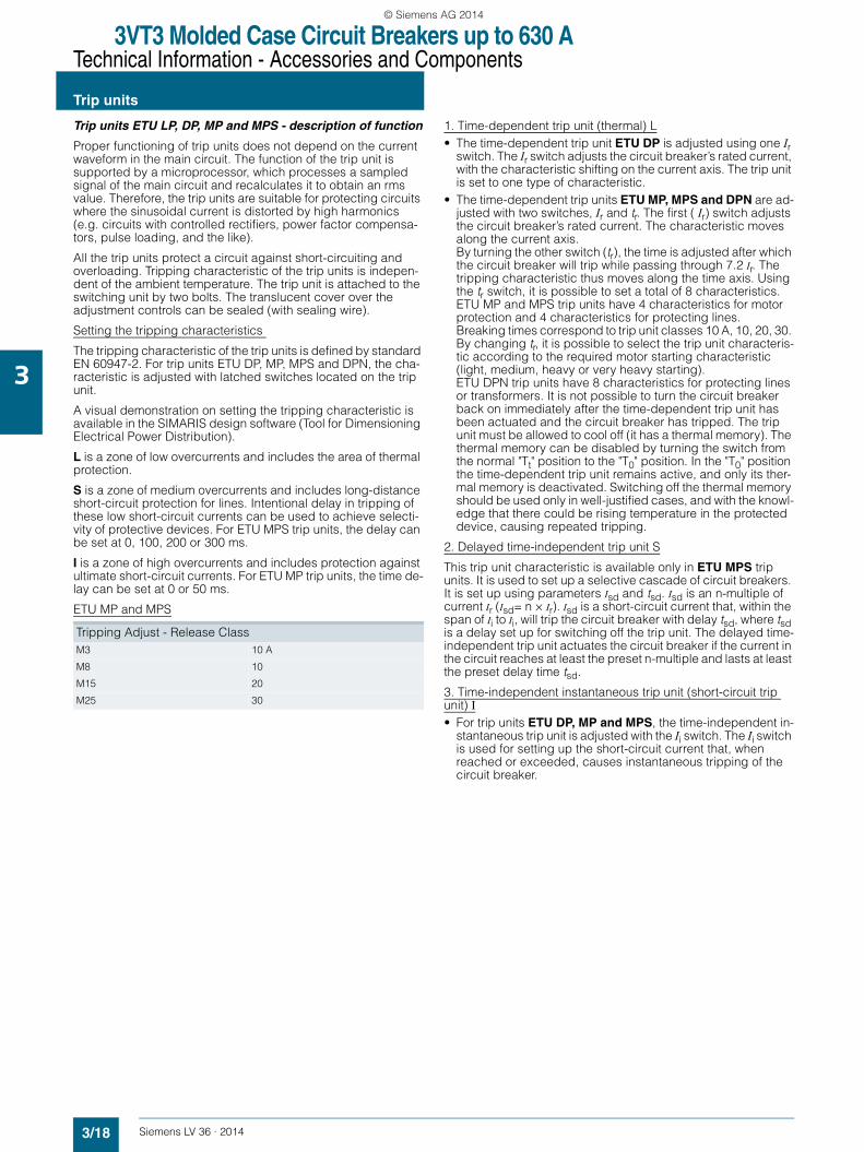
Tripping Adjust - Release ClassM3 10 A
M8 10
M15 20
M25 30
LV36_2014.book Seite 18 Freitag, 31. Januar 2014 4:36 16
© Siemens AG 2014
3VT3 Molded Case Circuit Breakers up to 630 ATechnical Information - Accessories and Components
Trip units
3/19Siemens LV 36 · 2014
3
Tripping characteristics of ETU LP, DP, MP, MPS and DPNtrip units with load
The tripping characteristic from the cold state indicates the tripping times during which it is assumed that, up to the moment when an overcurrent develops, no current is flowing through the circuit breaker. The tripping characteristic tripped from warm state indicates the tripping times during which it is assumed that, before the moment when an overcurrent develops, current is flowing through the circuit breaker. Characteristics of electronic trip units are independent of the ambient temperature and are plotted in a cold state. Digital trip units enable simulation of trip-ping in warm state. The tripping times become shorter in a steady state, as shown in the following diagram. The steady state is a period during which the characteristic does not change. If the circuit breaker is loaded with a reduced current for at least 30 minutes, the tripping times will be cut by a half. If the load is less than 70% of Ir , the tripping time does not become shorter.
Decrease of tripping time with load
T - When tripping from the trip unit’s "warm" state, the tripping time of the characteristic is cut short during the standstill time tu by coefficient k.
Thermal standstill time of the characteristics
For all trip units, the thermal standstill time is tu ≥ 30 min. During this time, the tripping time tsd is cut short from the cold-state cha-racteristic by the coefficient k.
The real tripping time is ts = k . tsd
Example
The shortening constant can be read from the diagram. With steady current 85% of Ir the real tripping time will be decreased to:
ts = 0.74 . tsd
k [–] time shortening coefficient
Ir [A] adjusted rated current of the trip units
tsd [s] tripping time of the trip unit, derived from the characteristic
ts [s] real tripping time of the trip unit, tripped from warm state
tu [s] standstill period for particular characteristics
Trip units are preset by the manufacturer
Ir = min
Restart = T(t)
Ii = min, 0 ms
tr = TV, t(t), min
Isd = 0 ms, min
IN = 0.5 Ir
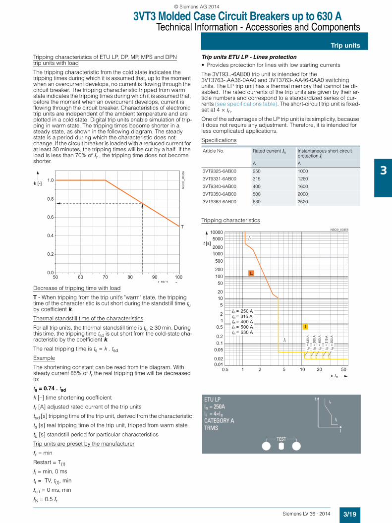
Trip units ETU LP - Lines protection• Provides protection for lines with low starting currents
The 3VT93..-6AB00 trip unit is intended for the 3VT3763-.AA36-0AA0 and 3VT3763-.AA46-0AA0 switching units. The LP trip unit has a thermal memory that cannot be di-sabled. The rated currents of the trip units are given by their ar-ticle numbers and correspond to a standardized series of cur-rents (see specifications table). The short-circuit trip unit is fixed-set at 4 × In.
One of the advantages of the LP trip unit is its simplicity, because it does not require any adjustment. Therefore, it is intended for less complicated applications.
Specifications
Tripping characteristics
NS
O0_
0035
5
I [%]
1.0
T
0.8
0.6
0.4
0.2
0.050 60 70 80 90 100
k [-]
Article No. Rated current In Instantaneous short circuit protection Ii
A A
3VT9325-6AB00 250 1000
3VT9331-6AB00 315 1260
3VT9340-6AB00 400 1600
3VT9350-6AB00 500 2000
3VT9363-6AB00 630 2520
20
200
2000
50
500
5000
10
100
1000
10000
t [s]
NSO0_00356
1 2 5 20 50100.5x In
0.010.02
0.050.10.2
0.512
5
I
L
Ir
Ii
I n =
630
A
I n =
500
AI n
= 4
00 A
I n =
315
AI n
= 2
50 A
In = 250 AIn = 315 AIn = 400 AIn = 500 AIn = 630 A
LV36_2014.book Seite 19 Freitag, 31. Januar 2014 4:36 16
© Siemens AG 2014
3VT3 Molded Case Circuit Breakers up to 630 ATechnical Information - Accessories and Components
Trip units
3/20 Siemens LV 36 · 2014
3
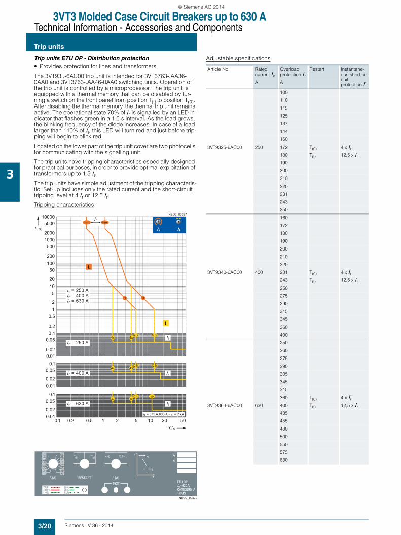
Trip units ETU DP - Distribution protection• Provides protection for lines and transformers
The 3VT93..-6AC00 trip unit is intended for 3VT3763-.AA36-0AA0 and 3VT3763-.AA46-0AA0 switching units. Operation of the trip unit is controlled by a microprocessor. The trip unit is equipped with a thermal memory that can be disabled by tur-ning a switch on the front panel from position T(t) to position T(0). After disabling the thermal memory, the thermal trip unit remains active. The operational state 70% of Ir is signalled by an LED in-dicator that flashes green in a 1.5 s interval. As the load grows, the blinking frequency of the diode increases. In case of a load larger than 110% of Ir, this LED will turn red and just before trip-ping will begin to blink red.
Located on the lower part of the trip unit cover are two photocells for communicating with the signalling unit.
The trip units have tripping characteristics especially designed for practical purposes, in order to provide optimal exploitation of transformers up to 1.5 Ir. The trip units have simple adjustment of the tripping characteris-tic. Set-up includes only the rated current and the short-circuit tripping level at 4 Ir or 12.5 Ir.Tripping characteristics
Adjustable specifications
NSO0_00357
xIn1 2 5 20 50100.1 0.2 0.5
Ir = 575 A.630 A ~ I i = 7 kA
4x12.5x
4x12.5x
4x12.5x
4x12.5x
4x12.5x
4x12.5x
I
In = 250 A
In = 400 A
In = 630 A Ii
Ii
Ii
In = 250 AIn = 400 AIn = 630 A
L
Ir Ii
0.02
0.02
0.05
0.05
0.01
0.01
20
200
2000
50
500
5000
10
100
1000
10000
t [s]
0.010.02
0.050.1
0.1
0.1
0.2
0.512
5
Irmin. max.
33
NSO0_00570
Article No. Rated current In
Overload protection Ir
Restart Instantane-ous short cir-cuit protection Ii
A A
100
110
115
125
137
144
160
3VT9325-6AC00 250 172 T(0) 4 x Ir
180 T(t) 12,5 x Ir
190
200
210
220
231
243
250
160
172
180
190
200
210
220
3VT9340-6AC00 400 231 T(0) 4 x Ir
243 T(t) 12,5 x Ir
250
275
290
315
345
360
400
250
260
275
290
305
345
315
360 T(0) 4 x Ir
3VT9363-6AC00 630 400 T(t) 12,5 x Ir
435
455
480
500
550
575
630
LV36_2014.book Seite 20 Freitag, 31. Januar 2014 4:36 16
© Siemens AG 2014

3VT3 Molded Case Circuit Breakers up to 630 ATechnical Information - Accessories and Components
Trip units
3/21Siemens LV 36 · 2014
3
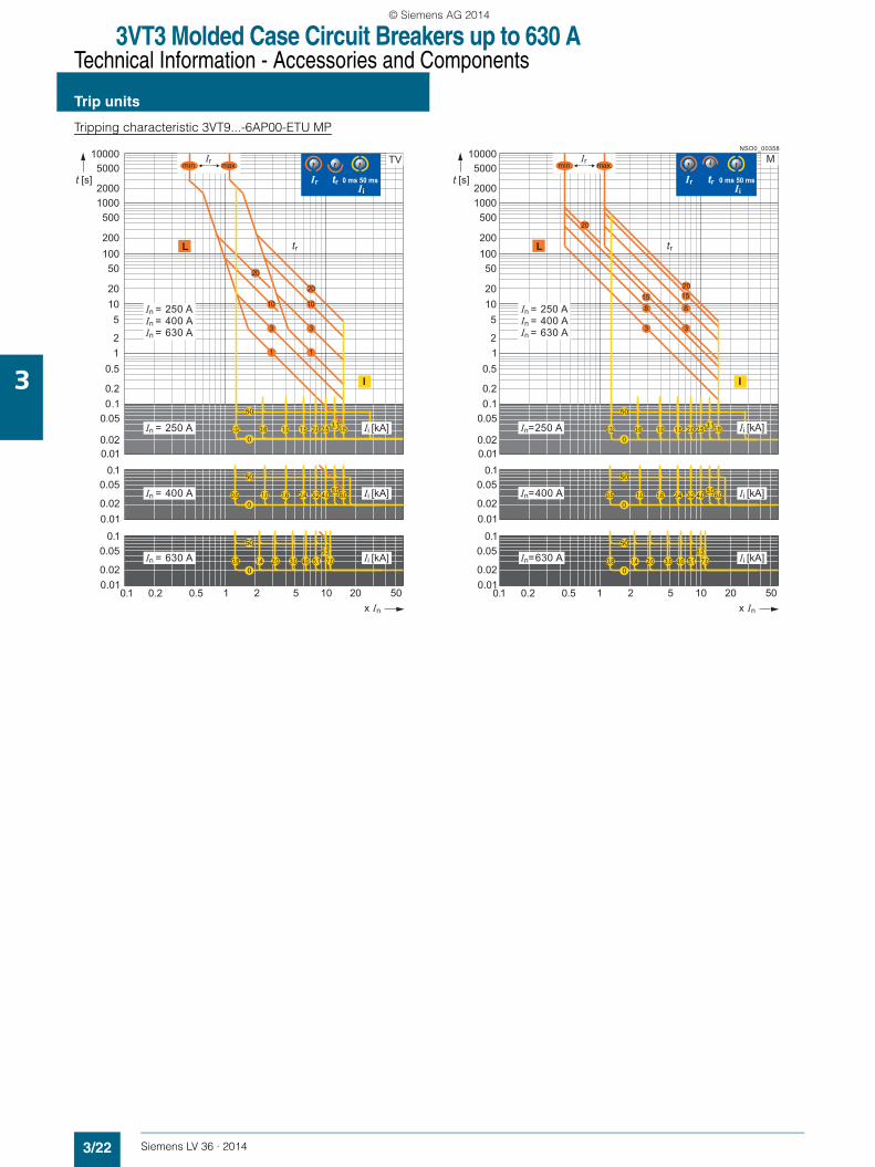
Trip units ETU MP - Motor protection• Provides protection for motors and generators• Can protect lines and transformers
The 3VT93..-6AP00 trip unit is intended for 3VT3763-.AA36-0AA0 and 3VT3763-.AA46-0AA0 switching units. The operation of the MP trip unit is controlled by a microprocessor. The MP trip unit is equipped with a thermal memory that can be disabled by turning a switch located on the front panel from position T(t) to position T(0). After disabling of the thermal memory, the thermal trip unit remains active.
When one or two phases fail (due to current greater than Ir in the remaining phases), in the M-characteristic mode, the switch will open with a 4 s delay (so-called undercurrent trip unit).
Another parameter for adjusting the trip unit consists of the rated current and short-circuit tripping level. The time delay of the short-circuit trip unit can be set to 0 ms or 50 ms. The operational state 70% of Ir is signalled by an LED indicator that flashes green in a 1.5 s interval. As the load grows, the blinking frequency of the diode increases. In case of a load larger than 110% of Ir, this LED will turn red and just before tripping will begin to blink red. Located on the lower part of the trip unit cover are two photocells for communicating with the signalling unit.
The trip units have tripping characteristics especially designed for practical purposes that provide for optimal exploitation of transformers up to 1.5 Ir. A total of 8 characteristics can be set on the trip unit. Mode "M" provides 4 characteristics suitable for protecting motors and in mode "TV" are 4 characteristics for pro-tecting transformers and lines. The shape of each characteristic can be changed using a selector switch.
Adjustable specifications
NSO0_00571
Article No. Rated current In
Overload protection Ir
tr (7.2 x Ir) Restart Instantaneous short circuit protection Ii
A A s kA ms
100 1 (TV 1) T(0) 0,32
110 3 (TV 3) T(0) 0,6
115 10 (TV 10) T(0) 1,0
125 20 (TV 20) T(0) 1,5 0
137 20 (M 20) T(0) 2,0
144 15 (M 15) T(0) 2,5
160 8 (M 8) T(0) 3,1
3VT9325-6AP00 250 172 3 (M 3) T(0) 3,75
180 3 (M 3) T(t) 3,75
190 8 (M 8) T(t) 3,1
200 15 (M 15) T(t) 2.5
210 20 (M 20) T(t) 2,0 50
220 20 (TV 20) T(t) 1,5
231 10 (TV 10) T(t) 1,0
243 3 (TV 3) T(t) 0,6
250 1 (TV 1) T(t) 0,32
160 1 (TV 1) T(0) 0,5
172 3 (TV 3) T(0) 1,0
180 10 (TV 10) T(0) 1,6
190 20 (TV 20) T(0) 2,4
200 20 (M 20) T(0) 3,2 0
210 15 (M 15) T(0) 4,0
220 8 (M 8) T(0) 5,0
3VT9340-6AP00 400 231 3 (M 3) T(0) 6,0
243 3 (M 3) T(t) 6,0
250 8 (M 8) T(t) 5,0
275 15 (M 15) T(t) 4,0
290 20 (M 20) T(t) 3,2
315 20 (TV 20) T(t) 2,4 50
345 10 (TV 10) T(t) 1,6
360 3 (TV 3) T(t) 1
400 1 (TV 1) T(t) 0,5
250 1 (TV 1) T(0) 0,8
260 3 (TV 3) T(0) 1,4
275 10 (TV 10) T(0 2
290 20 (TV 20) T(0)) 3 0
305 20 (M 20) T(0) 4
315 15 (M 15) T(0) 5,1
345 8 (M 8) T(0) 6,3
3VT9363-6AP00 630 360 3 (M 3) T(0) 7
400 3 (M 3) T(t) 6,3
435 8 (M 8) T(t) 6,3
455 15 (M 15) T(t) 5,1
480 20 (M 20) T(t) 4
500 20 (TV 20) T(t) 3 50
550 10 (TV 10) T(t) 2
575 3 (TV 3) T(t) 1,4
630 1 (TV 1) T(t) 0,8
LV36_2014.book Seite 21 Freitag, 31. Januar 2014 4:36 16
© Siemens AG 2014
3VT3 Molded Case Circuit Breakers up to 630 ATechnical Information - Accessories and Components
Trip units
3/22 Siemens LV 36 · 2014
3
Tripping characteristic 3VT9...-6AP00-ETU MP
NSO0_00358
x In1 2 5 20 50100.1 0.2 0.5
x In1 2 5 20 50100.1 0.2 0.5
0.02
0.02
0.05
0.05
0.01
0.01
20
200
2000
50
500
5000
10
100
1000
10000
t [s]
0.010.02
0.050.1
0.1
0.1
0.2
0.512
5
0.02
0.02
0.05
0.05
0.01
0.01
20
200
2000
50
500
5000
10
100
1000
10000
t [s]
0.010.02
0.050.1
0.1
0.1
0.2
0.512
5
20
1010
33
11
20
201515
33
88
20
TV
Ir tr 0 ms 50 ms Ii
L L
I I
tr tr
In = 250 A
In = 250 AIn = 400 AIn = 630 A
In = 400 A
In = 630 A
In=250 A
In = 250 AIn = 400 AIn = 630 A
In=400 A
In=630 A
M
Ir tr 0 ms 50 ms Ii
3.753.12.52.01.51.00.60.320
50
6.05.04.03.22.41.61.00.50
50
7.06.3
5.14.03.01.4 2.00.80
50
3.753.12.52.01.51.00.60.320
50
6.05.04.03.22.41.61.00.50
50
7.06.3
5.14.03.01.4 2.00.80
50
Ii [kA]
Ii [kA]
Ii [kA]
Ii [kA]
Ii [kA]
Ii [kA]
Irmin. max.Irmin. max.
LV36_2014.book Seite 22 Freitag, 31. Januar 2014 4:36 16
© Siemens AG 2014
3VT3 Molded Case Circuit Breakers up to 630 ATechnical Information - Accessories and Components
Trip units
3/23Siemens LV 36 · 2014
3
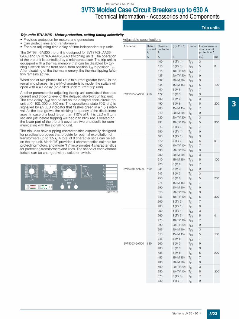
Trip units ETU MPS - Motor protection, setting timing selectivity• Provides protection for motors and generators• Can protect lines and transformers• Enables adjusting time delay of time-independent trip units
The 3VT93..-6AS00 trip unit is designed for 3VT3763-.AA36-0AA0 and 3VT3763-.AA46-0AA0 switching units. The operation of the trip unit is controlled by a microprocessor. The trip unit is equipped with a thermal memory that can be disabled by tur-ning a switch on the front panel from position T(t) to position T(0). After disabling of the thermal memory, the thermal tipping func-tion remains active.
When one or two phases fail (due to current greater than Ir in the remaining phases), in the M-characteristic mode, the switch will open with a 4 s delay (so-called undercurrent trip unit).
Another parameter for adjusting the trip unit consists of the rated current and tripping level of the delayed short-circuit trip unit. The time delay (tsd) can be set on the delayed short-circuit trip unit at 0, 100, 200 or 300 ms. The operational state 70% of Ir is signalled by an LED indicator that flashes green in a 1.5 s inter-val. As the load grows, the blinking frequency of the diode incre-ases. In case of a load larger than 110% of Ir, this LED will turn red and just before tripping will begin to blink red. Located on the lower part of the trip unit cover are two photocells for com-municating with the signalling unit.
The trip units have tripping characteristics especially designed for practical purposes that provide for optimal exploitation of transformers up to 1.5 Ir. A total of 8 characteristics can be set on the trip unit. Mode "M" provides 4 characteristics suitable for protecting motors, and mode "TV" incorporates 4 characteristics for protecting transformers and lines. The shape of each charac-teristic can be changed with a selector switch.
Adjustable specifications
NSO0_00572
Article No. Rated current In
Overload protection Ir
tr (7.2 x Ir) Restart Instantaneous short circuit protection Ii
A A S x Ir ms
100 1 (TV 1) T(0) 3
110 3 (TV 3) T(0) 5 0
115 10 (TV 10) T(0) 7
125 20 (TV 20) T(0) 9
137 20 (M 20) T(0) 3
144 15 (M 15) T(0) 5 100
160 8 (M 8) T(0) 7
3VT9325-6AS00 250 172 3 (M 3) T(0) 9
180 3 (M 3) T(t) 3
190 8 (M 8) T(t) 5 200
200 15 (M 15) T(t) 7
210 20 (M 20) T(t) 9
220 20 (TV 20) T(t) 3
231 10 (TV 10) T(t) 5 300
243 3 (TV 3) T(t) 7
250 1 (TV 1) T(t) 9
160 1 (TV 1) T(0) 3
172 3 (TV 3) T(0) 5 0
180 10 (TV 10) T(0) 7
190 20 (TV 20) T(0) 9
200 20 (M 20) T(0) 3
210 15 (M 15) T(0) 5 100
220 8 (M 8) T(0) 7
3VT9340-6AS00 400 231 3 (M 3) T(0) 9
243 3 (M 3) T(t) 3
250 8 (M 8) T(t) 5 200
275 15 (M 15) T(t) 7
290 20 (M 20) T(t) 9
315 20 (TV 20) T(t) 3
345 10 (TV 10) T(t) 5 300
360 3 (TV 3) T(t) 7
400 1 (TV 1) T(t) 9
250 1 (TV 1) T(0) 3
260 3 (TV 3) T(0) 5 0
275 10 (TV 10) T(0) 7
290 20 (TV 20) T(0) 9
305 20 (M 20) T(0) 3
315 15 (M 15) T(0) 5 100
345 8 (M 8) T(0) 7
3VT9363-6AS00 630 360 3 (M 3) T(0) 9
400 3 (M 3) T(t) 3
435 8 (M 8) T(t) 5 200
455 15 (M 15) T(t) 7
480 20 (M 20) T(t) 9
500 20 (TV 20) T(t) 3
550 10 (TV 10) T(t) 5 300
575 3 (TV 3) T(t) 7
630 1 (TV 1) T(t) 9
LV36_2014.book Seite 23 Freitag, 31. Januar 2014 4:36 16
© Siemens AG 2014
3VT3 Molded Case Circuit Breakers up to 630 ATechnical Information - Accessories and Components
Trip units
3/24 Siemens LV 36 · 2014
3
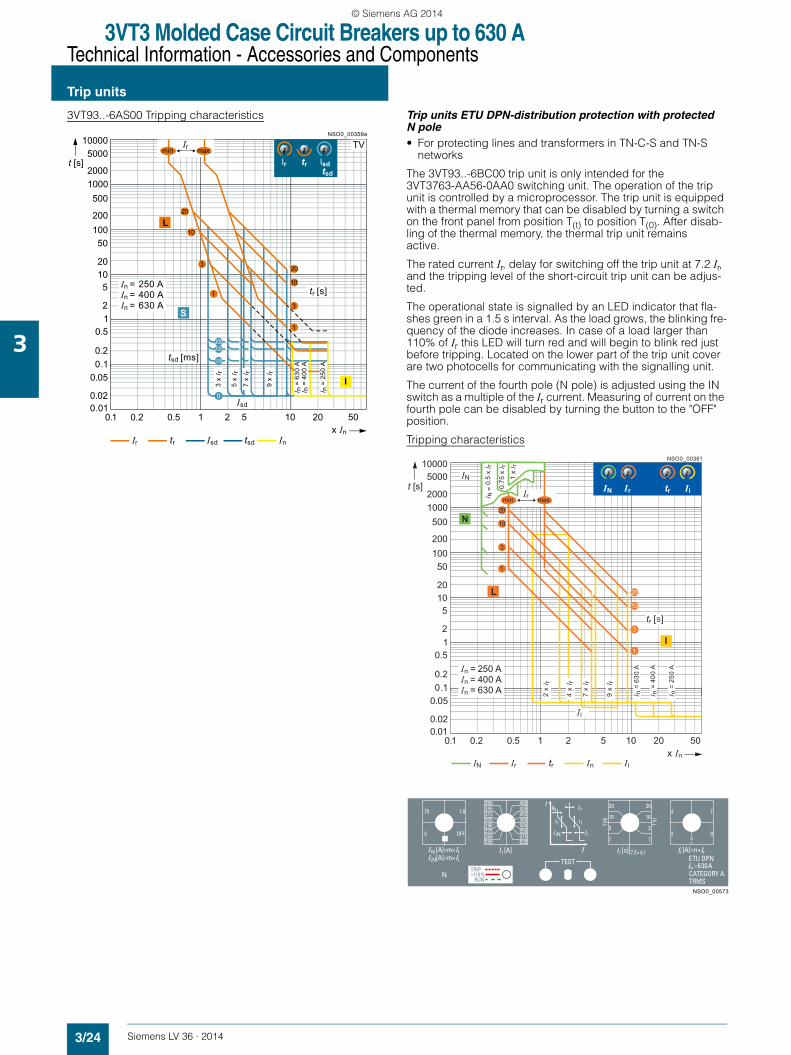
3VT93..-6AS00 Tripping characteristics Trip units ETU DPN-distribution protection with protected N pole• For protecting lines and transformers in TN-C-S and TN-S
networks
The 3VT93..-6BC00 trip unit is only intended for the 3VT3763-AA56-0AA0 switching unit. The operation of the trip unit is controlled by a microprocessor. The trip unit is equipped with a thermal memory that can be disabled by turning a switch on the front panel from position T(t) to position T(0). After disab-ling of the thermal memory, the thermal trip unit remainsactive.
The rated current Ir, delay for switching off the trip unit at 7.2 Ir, and the tripping level of the short-circuit trip unit can be adjus-ted.
The operational state is signalled by an LED indicator that fla-shes green in a 1.5 s interval. As the load grows, the blinking fre-quency of the diode increases. In case of a load larger than 110% of Ir this LED will turn red and will begin to blink red just before tripping. Located on the lower part of the trip unit cover are two photocells for communicating with the signalling unit.
The current of the fourth pole (N pole) is adjusted using the IN switch as a multiple of the Ir current. Measuring of current on the fourth pole can be disabled by turning the button to the "OFF" position.
Tripping characteristics
20
200
2000
50
500
5000
10
100
1000
10000
t [s]
NSO0_00359a
1 2 5 20 50100.1 0.2 0.5x In
0.010.02
0.050.10.2
0.512
5
300200
100
0
20
10
3
1
20
10
3
1
TV
In = 250 AIn = 400 AIn = 630 A
tsd [ms]
Isd
I n =
250
A
I n =
400
AI n
= 6
30 A
Ir tr Isdtsd
L
S
I
tr [s]
9 x I r
7 x I r
5 x I r
3 x I r
Irmin max.
Ir tr tsdIsd In
20
200
2000
50
500
5000
10
100
1000
10000
t [s]
NSO0_00361
1 2 5 20 50100.1 0.2 0.5x In
0.010.02
0.050.10.2
0.512
5
N
20
10
3
1
20
10
3
1
IiIrIN tr
IN
L
I
tr [S]
Ii
I n =
400
A
I n =
250
A
I n =
630
AIn = 250 AIn = 400 AIn = 630 A
Irmin. max.I N =
0.5
x I r
1 x I r
0.75
x I r
9 x I r
7 x I r
4 x I r
2 x I r
IN Ir tr In Ii
NSO0_00573
LV36_2014.book Seite 24 Freitag, 31. Januar 2014 4:36 16
© Siemens AG 2014

3VT3 Molded Case Circuit Breakers up to 630 ATechnical Information - Accessories and Components
Trip units
3/25Siemens LV 36 · 2014
3
Adjustable specifications
Article No. Rated current In Overload protection Ir tr (7.2 x Ir) Restart Instantaneous short circuit protection Ii
A A S x Ir ms
100 1
110 2 0,5
115 3 T(0)
125
137 10
144 4 0,75
160 20
3VT9325-6BC00 250 172
180 20
190 7 1
200 10 T(t)
210
220 3
231 9 OFF
243 1
250
160 1
172 2 0,5
180 3 T(0)
190
200 10
210 4 0,75
220 20
3VT9340-6BC00 400 231
243 20
250 7 1
275 10 T(t)
290
315 3
345 9 OFF
360 1
400
250 1
260 2 0,5
275 3 T(0)
290
305 10
315 4 0,75
345 20
3VT9363-6BC00 630 360
400 20
435 7 1
455 10 T(t)
480
500 3
550 9 OFF
575 1
630
LV36_2014.book Seite 25 Freitag, 31. Januar 2014 4:36 16
© Siemens AG 2014
3VT3 Molded Case Circuit Breakers up to 630 ATechnical Information - Accessories and Components
Auxiliary switches
3/26 Siemens LV 36 · 2014
3
■ Overview
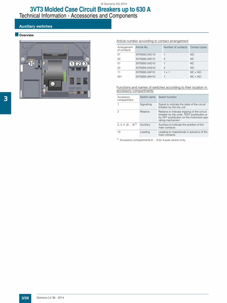
Article number according to contact arrangement
Functions and names of switches according to their location in accessory compartments
1) Accessory compartments 6 ... 9 for 4-pole version only.
Arrangement of contacts
Article No. Number of contacts Contact types
01 3VT9300-2AC10 1 NO
20 3VT9300-2AE10 2 NC
01 3VT9300-2AD10 1 NC
02 3VT9300-2AG10 2 NO
11 3VT9300-2AF10 1 + 1 NC + NO
001 3VT9300-2AH10 1 NC + NO
Accessory compartment
Switch name Switch function
1 Signalling Signal to indicate the state of the circuit breaker by the trip unit
2 Relative Relative to indicate tripping of the circuit breaker by trip units, TEST pushbutton or by OFF pushbutton on the motorized ope-rating mechanism
3, 4, 5, (6 ... 9)1) Auxiliary Auxiliary to indicate the position of the main contacts
10 Leading Leading to make/break in advance of the main contacts
LV36_2014.book Seite 26 Freitag, 31. Januar 2014 4:36 16
© Siemens AG 2014
3VT3 Molded Case Circuit Breakers up to 630 ATechnical Information - Accessories and Components
Auxiliary switches
3/27Siemens LV 36 · 2014
3
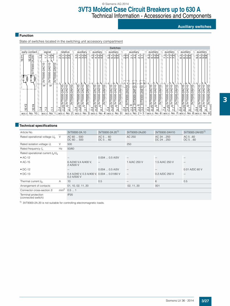
■ Function
State of switches located in the switching unit accessory compartment
■ Technical specifications
1) 3VT9300-2A.20 is not suitable for controlling electromagnetic loads.
3VT9
300-
2AC
103V
T930
0-2A
D10
3VT9
300-
2AH
10
3VT9
300-
2AG
10
3VT9
300-
2AF1
0
3VT9
300-
2AE
10
2.4
3.4
2.2
3.4
2.2
3.2
5.4
5.2
5.1
4.4
4.2
4.1
7.4
7.2
7.1
8.4
8.2
8.1
9.4
9.2
9.1
6.4
6.2
6.1
1.4
1.2
1.1
2.4
2.2
2.1
3.4
3.2
3.1
10.Y
2
10.Y
4
3VT9
300-
2AC
10
3VT9
300-
2AD
10
3VT9
300-
2AH
10
10.Y
1
10.Y
33V
T930
0-2A
J00
2.3
3.3
2.1
3.3
2.1
3.1
5.3
5.1
5.2
5.4
4.3
4.1
4.2
4.4
7.3
7.1
7.2
7.4
8.3
8.1
8.2
8.4
9.3
9.1
9.2
9.4
6.3
6.1
6.2
6.4
1.3
1.1
1.2
1.4
2.3
2.1
2.2
2.4
3.3
3.1
3.2
3.4
3VT9
300-
2AC
103V
T930
0-2A
D10
3VT9
300-
2AH
10
3VT9
300-
2AC
103V
T930
0-2A
D10
3VT9
300-
2AH
10
3VT9
300-
2AC
103V
T930
0-2A
D10
3VT9
300-
2AH
10
3VT9
300-
2AC
103V
T930
0-2A
D10
3VT9
300-
2AH
10
3VT9
300-
2AC
103V
T930
0-2A
D10
3VT9
300-
2AH
10
3VT9
300-
2AC
103V
T930
0-2A
D10
3VT9
300-
2AH
10
3VT9
300-
2AC
103V
T930
0-2A
D10
3VT9
300-
2AH
10N
SO
0_00
362a
auxiliary
acc.c. No. 2 + 3
or or
acc.c. No. 5acc.c. No. 4
auxiliaryauxiliary
orororor
Switches
acc.c. No. 6
auxiliary auxiliary auxiliary auxiliary
acc.c. No. 7 acc.c. No. 8 acc.c. No. 9
oror oror orororor
signal
acc.c. No. 1
relative auxiliary
acc.c. No. 2 acc.c. No. 3
oror oror
early contact
acc.c. No. 10
or or
Article No. 3VT9300-2A.10 3VT9300-2A.201) 3VT9300-2AJ00 3VT9300-2AH10 3VT9300-2AH201)
Rated operational voltage Ue V AC 60 ... 500DC 60 ... 500
AC 5 ... 60DC 5 ... 60
AC 250 AC 24 ...250DC 24 ...250
AC 5 ..60DC 5 ...60
Rated isolation voltage Ui V 500 250
Rated frequency fn Hz 50/60
Rated operational current Ie/Ue
• AC-12 -- 0.004 ... 0.5 A/5V -- -- --
• AC-15 6 A/240 V,4 A/400 V, 2 A/500 V
-- 1 A/AC 250 V 1.5 A/AC 250 V --
• DC-12 -- 0.004 ... 0.5 A/5V -- -- 0.01 A/DC 60 V
• DC-13 0.4 A/240 V, 0.3 A/400 V, 0.2 A/500 V
0.004 ... 0.01/60 V -- 0.2 A/DC 250 V --
Thermal current Ith A 10 0.5 -- 6 0.5
Arrangement of contacts 01, 10, 02, 11, 20 02, 11, 20 001
Connector cross-section S mm2 0.5 ... 1
Terminal protection (connected switch)
IP20
LV36_2014.book Seite 27 Freitag, 31. Januar 2014 4:36 16
© Siemens AG 2014
3VT3 Molded Case Circuit Breakers up to 630 ATechnical Information - Accessories and Components
Auxiliary trip units
3/28 Siemens LV 36 · 2014
3
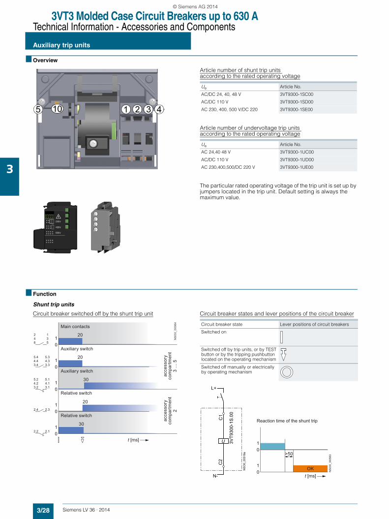
■ Overview
Article number of shunt trip units according to the rated operating voltage
Article number of undervoltage trip units according to the rated operating voltage
The particular rated operating voltage of the trip unit is set up by jumpers located in the trip unit. Default setting is always the maximum value.
■ Function
Shunt trip units
Circuit breaker switched off by the shunt trip unit Circuit breaker states and lever positions of the circuit breaker
Ue Article No.
AC/DC 24, 40, 48 V 3VT9300-1SC00
AC/DC 110 V 3VT9300-1SD00
AC 230, 400, 500 V/DC 220 3VT9300-1SE00
Ue Article No.
AC 24,40 48 V 3VT9300-1UC00
AC/DC 110 V 3VT9300-1UD00
AC 230,400,500/DC 220 V 3VT9300-1UE00
20
20
20
30
20
30
01
01
01
01
01
t [ms]
NS
O0_
0036
4
246
135
5.44.43.4
5.34.33.3
5.24.23.2
5.14.13.1
2.4 2.3
2.2 2.1
Main contacts
Auxiliary switch
Auxiliary switch
Relative switch
Relative switch
acce
ssor
yco
mpa
rtm
ent
2
acce
ssor
yco
mpa
rtm
ent
3 …
5
Circuit breaker state Lever positions of circuit breakers
Switched on
Switched off by trip units, or by TEST button or by the tripping pushbutton located on the operating mechanism
Switched off manually or electrically by operating mechanism
C1
U
C2
N-
3VT9
300-
1S.0
0
L+
NS
O0_
0051
8a
OK
>50
01
01
t [ms]
NS
O0_
0058
3
Reaction time of the shunt trip
LV36_2014.book Seite 28 Freitag, 31. Januar 2014 4:36 16
© Siemens AG 2014
3VT3 Molded Case Circuit Breakers up to 630 ATechnical Information - Accessories and Components
Auxiliary trip units
3/29Siemens LV 36 · 2014
3
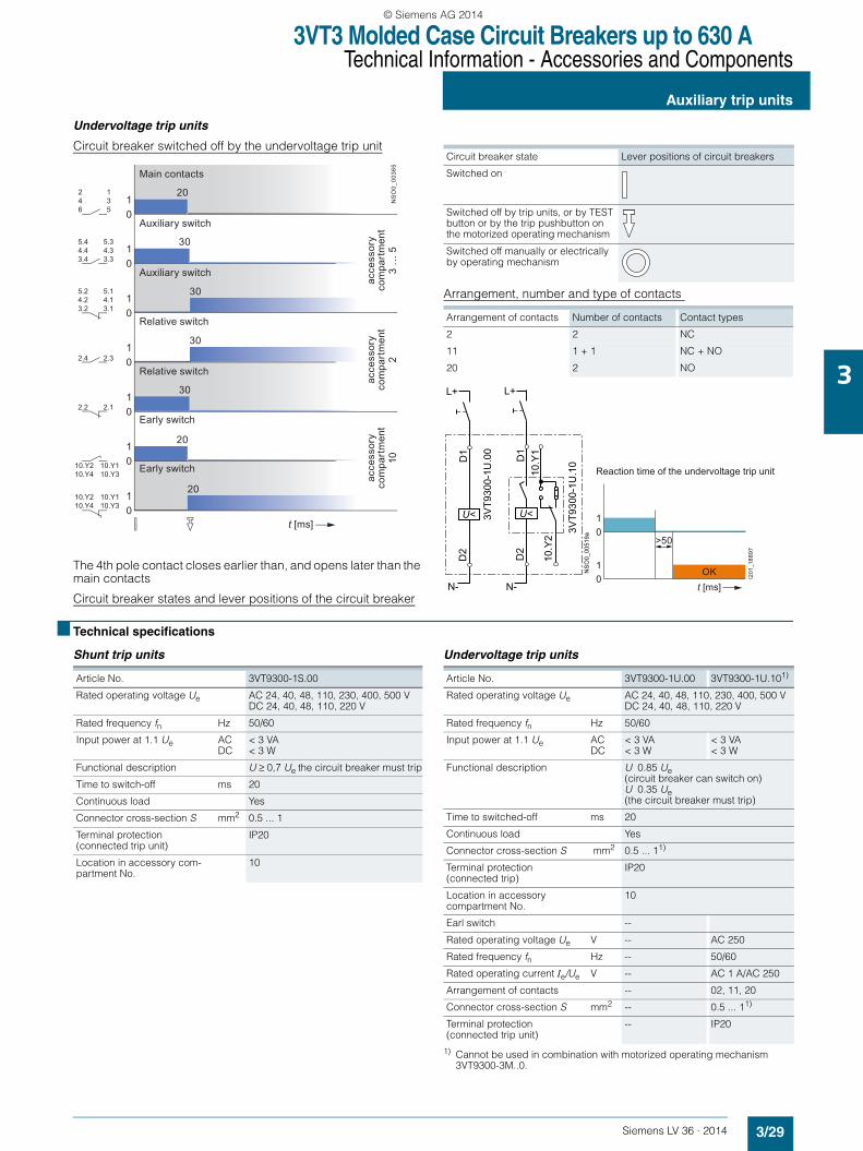
Undervoltage trip units
Circuit breaker switched off by the undervoltage trip unit
The 4th pole contact closes earlier than, and opens later than the main contacts
Circuit breaker states and lever positions of the circuit breaker
Arrangement, number and type of contacts
■ Technical specifications
Shunt trip units Undervoltage trip units
1) Cannot be used in combination with motorized operating mechanism 3VT9300-3M..0.
20
30
30
30
20
30
01
01
01
01
01
01
01
t [ms]
20
NS
O0_
0036
5
246
135
5.44.43.4
5.34.33.3
5.24.23.2
5.14.13.1
2.4 2.3
2.2 2.1
10.Y210.Y4
10.Y110.Y3
10.Y210.Y4
10.Y110.Y3
Main contacts
Auxiliary switch
Auxiliary switch
Relative switch
Relative switch
Early switch
Early switch
acce
ssor
yco
mpa
rtm
ent
2
acce
ssor
yco
mpa
rtm
ent
3 …
5
acce
ssor
yco
mpa
rtm
ent
10
Circuit breaker state Lever positions of circuit breakers
Switched on
Switched off by trip units, or by TEST button or by the trip pushbutton on the motorized operating mechanism
Switched off manually or electrically by operating mechanism
Arrangement of contacts Number of contacts Contact types
2 2 NC
11 1 + 1 NC + NO
20 2 NO
D1
U<D
2
10.Y
2
N-
L+
NS
O0_
0051
9a
10.Y
1
D1
U<
D2
N-
L+
3VT9
300-
1U.0
0
3VT9
300-
1U.1
0OK
>50
01
01
t [ms]
I201
_188
97
Reaction time of the undervoltage trip unit
Article No. 3VT9300-1S.00
Rated operating voltage Ue AC 24, 40, 48, 110, 230, 400, 500 VDC 24, 40, 48, 110, 220 V
Rated frequency fn Hz 50/60
Input power at 1.1 Ue ACDC
< 3 VA< 3 W
Functional description U ≥ 0,7 Ue the circuit breaker must trip
Time to switch-off ms 20
Continuous load Yes
Connector cross-section S mm2 0.5 ... 1
Terminal protection(connected trip unit)
IP20
Location in accessory com-partment No.
10
Article No. 3VT9300-1U.00 3VT9300-1U.101)
Rated operating voltage Ue AC 24, 40, 48, 110, 230, 400, 500 VDC 24, 40, 48, 110, 220 V
Rated frequency fn Hz 50/60
Input power at 1.1 Ue ACDC
< 3 VA< 3 W
< 3 VA< 3 W
Functional description U 0.85 Ue (circuit breaker can switch on) U 0.35 Ue (the circuit breaker must trip)
Time to switched-off ms 20
Continuous load Yes
Connector cross-section S mm2 0.5 ... 11)
Terminal protection(connected trip)
IP20
Location in accessory compartment No.
10
Earl switch --
Rated operating voltage Ue V -- AC 250
Rated frequency fn Hz -- 50/60
Rated operating current Ie/Ue V -- AC 1 A/AC 250
Arrangement of contacts -- 02, 11, 20
Connector cross-section S mm2 -- 0.5 ... 11)
Terminal protection(connected trip unit)
-- IP20
LV36_2014.book Seite 29 Freitag, 31. Januar 2014 4:36 16
© Siemens AG 2014
3VT3 Molded Case Circuit Breakers up to 630 ATechnical Information - Accessories and Components
Rotary operating mechanisms
3/30 Siemens LV 36 · 2014
3
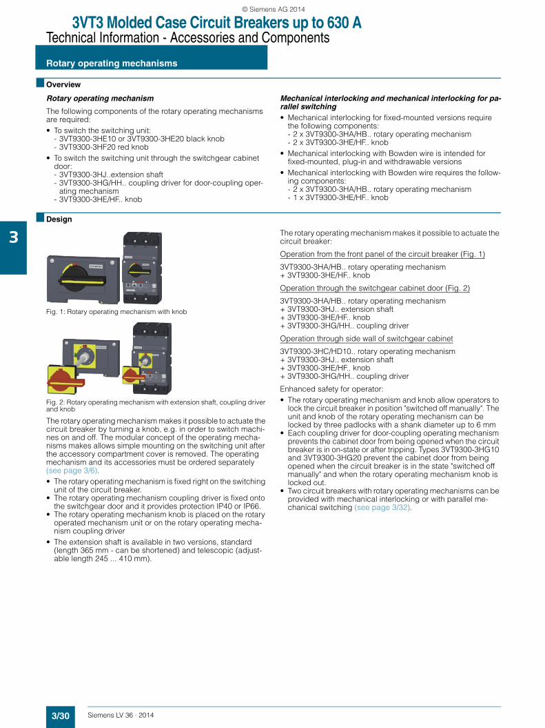
■ Overview
Rotary operating mechanism
The following components of the rotary operating mechanisms are required:• To switch the switching unit:
- 3VT9300-3HE10 or 3VT9300-3HE20 black knob- 3VT9300-3HF20 red knob
• To switch the switching unit through the switchgear cabinet door:- 3VT9300-3HJ..extension shaft- 3VT9300-3HG/HH.. coupling driver for door-coupling oper-
ating mechanism- 3VT9300-3HE/HF.. knob
Mechanical interlocking and mechanical interlocking for pa-rallel switching • Mechanical interlocking for fixed-mounted versions require
the following components:- 2 x 3VT9300-3HA/HB.. rotary operating mechanism- 2 x 3VT9300-3HE/HF.. knob
• Mechanical interlocking with Bowden wire is intended for fixed-mounted, plug-in and withdrawable versions
• Mechanical interlocking with Bowden wire requires the follow-ing components:- 2 x 3VT9300-3HA/HB.. rotary operating mechanism- 1 x 3VT9300-3HE/HF.. knob
■ Design
Fig. 1: Rotary operating mechanism with knob
Fig. 2: Rotary operating mechanism with extension shaft, coupling driver and knob
The rotary operating mechanism makes it possible to actuate the circuit breaker by turning a knob, e.g. in order to switch machi-nes on and off. The modular concept of the operating mecha-nisms makes allows simple mounting on the switching unit after the accessory compartment cover is removed. The operating mechanism and its accessories must be ordered separately (see page 3/6).• The rotary operating mechanism is fixed right on the switching
unit of the circuit breaker.• The rotary operating mechanism coupling driver is fixed onto
the switchgear door and it provides protection IP40 or IP66.• The rotary operating mechanism knob is placed on the rotary
operated mechanism unit or on the rotary operating mecha-nism coupling driver
• The extension shaft is available in two versions, standard (length 365 mm - can be shortened) and telescopic (adjust-able length 245 ... 410 mm).
The rotary operating mechanism makes it possible to actuate the circuit breaker:
Operation from the front panel of the circuit breaker (Fig. 1)
3VT9300-3HA/HB.. rotary operating mechanism + 3VT9300-3HE/HF.. knob
Operation through the switchgear cabinet door (Fig. 2)
3VT9300-3HA/HB.. rotary operating mechanism + 3VT9300-3HJ.. extension shaft + 3VT9300-3HE/HF.. knob + 3VT9300-3HG/HH.. coupling driver
Operation through side wall of switchgear cabinet
3VT9300-3HC/HD10.. rotary operating mechanism + 3VT9300-3HJ.. extension shaft + 3VT9300-3HE/HF.. knob + 3VT9300-3HG/HH.. coupling driver
Enhanced safety for operator:• The rotary operating mechanism and knob allow operators to
lock the circuit breaker in position "switched off manually". The unit and knob of the rotary operating mechanism can be locked by three padlocks with a shank diameter up to 6 mm
• Each coupling driver for door-coupling operating mechanism prevents the cabinet door from being opened when the circuit breaker is in on-state or after tripping. Types 3VT9300-3HG10 and 3VT9300-3HG20 prevent the cabinet door from being opened when the circuit breaker is in the state "switched off manually" and when the rotary operating mechanism knob is locked out.
• Two circuit breakers with rotary operating mechanisms can be provided with mechanical interlocking or with parallel me-chanical switching (see page 3/32).
LV36_2014.book Seite 30 Freitag, 31. Januar 2014 4:36 16
© Siemens AG 2014
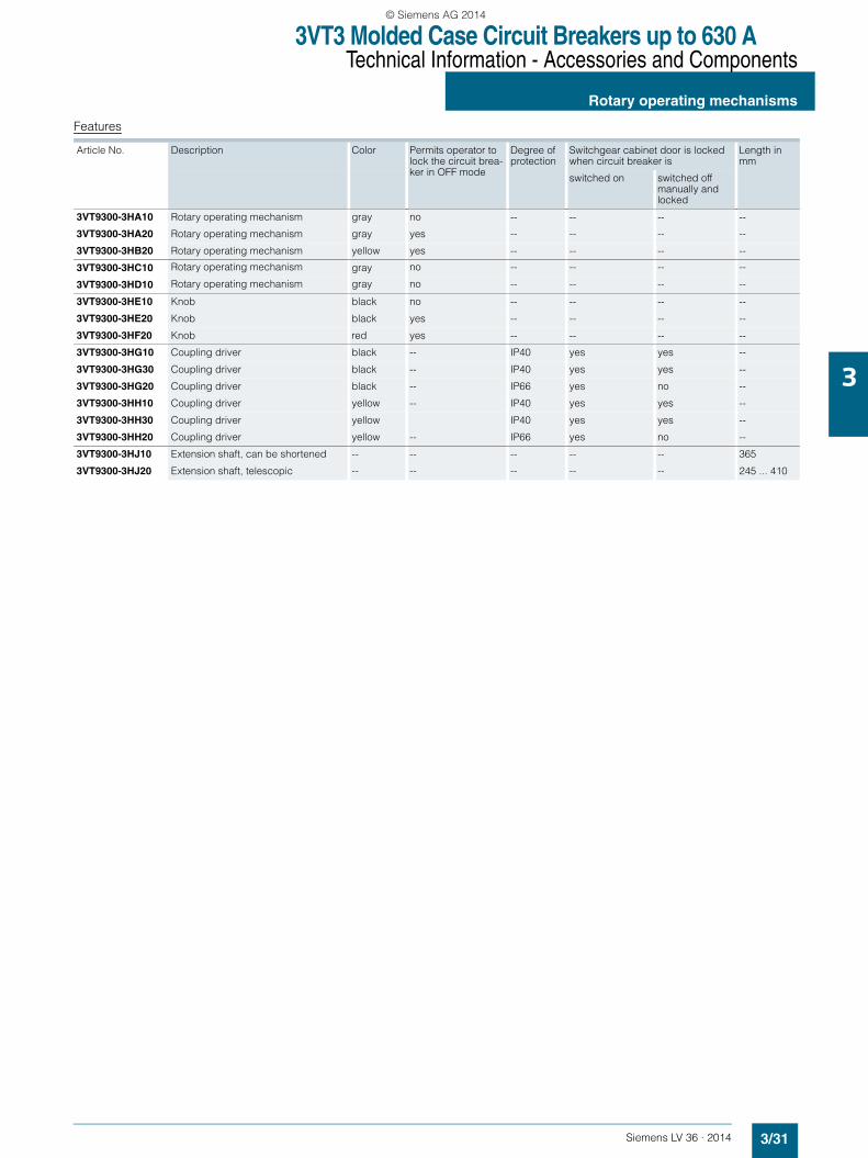
3VT3 Molded Case Circuit Breakers up to 630 ATechnical Information - Accessories and Components
Rotary operating mechanisms
3/31Siemens LV 36 · 2014
3
Features
Article No. Description Color Permits operator to lock the circuit brea-ker in OFF mode
Degree of protection
Switchgear cabinet door is locked when circuit breaker is
Length inmm
switched on switched off manually and locked
3VT9300-3HA10 Rotary operating mechanism gray no -- -- -- --
3VT9300-3HA20 Rotary operating mechanism gray yes -- -- -- --
3VT9300-3HB20 Rotary operating mechanism yellow yes -- -- -- --
3VT9300-3HC10 Rotary operating mechanism gray no -- -- -- --
3VT9300-3HD10 Rotary operating mechanism gray no -- -- -- --
3VT9300-3HE10 Knob black no -- -- -- --
3VT9300-3HE20 Knob black yes -- -- -- --
3VT9300-3HF20 Knob red yes -- -- -- --
3VT9300-3HG10 Coupling driver black -- IP40 yes yes --
3VT9300-3HG30 Coupling driver black -- IP40 yes yes --
3VT9300-3HG20 Coupling driver black -- IP66 yes no --
3VT9300-3HH10 Coupling driver yellow -- IP40 yes yes --
3VT9300-3HH30 Coupling driver yellow IP40 yes yes --
3VT9300-3HH20 Coupling driver yellow -- IP66 yes no --
3VT9300-3HJ10 Extension shaft, can be shortened -- -- -- -- -- 365
3VT9300-3HJ20 Extension shaft, telescopic -- -- -- -- -- 245 ... 410
LV36_2014.book Seite 31 Freitag, 31. Januar 2014 4:36 16
© Siemens AG 2014
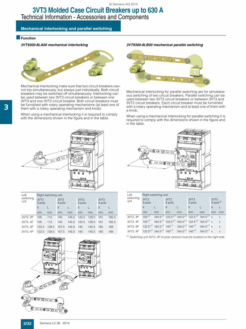
3VT3 Molded Case Circuit Breakers up to 630 ATechnical Information - Accessories and Components
Mechanical interlocking and parallel switching
3/32 Siemens LV 36 · 2014
3
■ Function
3VT9300-8LA00 mechanical interlocking
Mechanical interlocking make sure that two circuit breakers can-not trip simultaneously, but always just individually. Both circuit breakers may be switched off simultaneously. Interlocking can be used between two 3VT3 circuit breakers or between one 3VT3 and one 3VT2 circuit breaker. Both circuit breakers must be furnished with rotary operating mechanisms (at least one of them with a rotary operating mechanism and knob).
When using a mechanical interlocking it is required to comply with the dimensions shown in the figure and in the table.
3VT9300-8LB00 mechanical parallel switching
Mechanical interlocking for parallel switching are for simultane-ous switching of two circuit breakers. Parallel switching can be used between two 3VT3 circuit breakers or between 3VT3 and 3VT2 circuit breakers. Each circuit breaker must be furnished with a rotary operating mechanism and at least one of them with a knob.
When using a mechanical interlocking for parallel switching it is required to comply with the dimensions shown in the figure and in the table.
1) Switching unit 3VT3, 4P (4-pole version) must be located on the right side.
Left switching unit
Right switching unit
3VT2 3-pole
3VT2 4-pole
3VT3 3-pole
3VT3 4-pole
X L X L X L X L
mm mm mm mm mm mm mm mm
3VT2, 3P 105 112 140 145.5 122.5 128.5 181 185.5
3VT2, 4P 105 112 140 145.5 122.5 128.5 181 185.5
3VT3, 3P 122.5 128.5 157.5 145.5 140 145.5 185 189
3VT3, 4P 122.5 128.5 157.5 145.5 140 145.5 185 189
X
L
531
TEST
NS
O0_
0023
3
TEST
RP-BD-CK10
PSPSPSSPSV
TEST
RP-BD-CK10
PSPSPSSPSV
NS
O0_
0023
5
Left switching unit
Right switching unit
3VT2 3-pole
3VT2 4-pole
3VT3 3-pole
3VT3 4-pole1)
X L X L X L X L
mm mm mm mm mm mm mm mm
3VT2, 3P 105+7 164.5+7 122.5+7 164.5+7 122.5+7 164.5+7 x x
3VT2, 4P 105+7 164.5+7 122.5+7 164.5+7 122.5+7 164.5+7 x x
3VT3, 3P 122.5+7 164.5+7 140+7 164.5+7 140+7 164.5+7 x x
3VT3, 4P 122.5+7 164.5+7 140+7 164.5+7 140+7 164.5+7 x x
TEST
NS
O0_
0023
4
RP-BD-CK10
PSPSPS
X
LV36_2014.book Seite 32 Freitag, 31. Januar 2014 4:36 16
© Siemens AG 2014

3VT3 Molded Case Circuit Breakers up to 630 ATechnical Information - Accessories and Components
Mechanical interlocking and parallel switching
3/33Siemens LV 36 · 2014
3
3VT9.00-8LC.0 Mechanical interlocking with bowden wire • Provides mechanical interlocking of two circuit break-ers/switch-disconnectors so that they cannot both trip simulta-neously, but only one of them at a time. Both circuit breakers may be turned off simultaneously.
• 3VT9300-8LC10 mechanical interlocking is intended for two 3VT3 circuit breakers. 3VT9300-8LC20 interlocking is in-tended for one 3VT3 circuit breaker and one 3VT2.
• Circuit breakers may be in fixed, plug-in and withdrawable designs.
Circuit breaker installation in switchgear and controlgear assemblies
Detailed information is included in the "Instructions for use", which is available on our website: www.siemens.com/lowvoltage/product-support.
Article No. of mechanical interlocking
3VT9300-8LC10 3VT9300-8LC20
Circuit breaker types 3VT3 3VT2
3VT3 3VT3
NS
O0_
0036
6
0 ... 700
TEST
ON
OFF
TEST
ON
OFF
30
4514
8
R
= 4
0m
in
min. 80
LV36_2014.book Seite 33 Freitag, 31. Januar 2014 4:36 16
© Siemens AG 2014
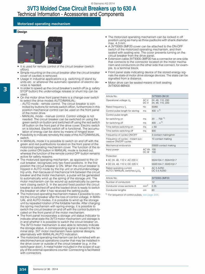
3VT3 Molded Case Circuit Breakers up to 630 ATechnical Information - Accessories and Components
Motorized operating mechanism
3/34 Siemens LV 36 · 2014
3
■ Design
• It is used for remote control of the circuit breaker (switch off/on).
• Simple mounting on the circuit breaker after the circuit breaker cover of cavities is removed.
• Usage in industrial applications e.g. switching of stand by units etc. or wherever the automatic operation of electric de-vices is needed.
• In order to speed up the circuit breaker‘s switch off (e.g. safety STOP button) the undervoltage release or shunt trip can be used.
• On the motor drive front panel there is a change-over switch to select the drive modes AUTO/MANUAL:- AUTO mode - remote control. The circuit breaker is con-
trolled by buttons for remote switch off/on, furthermore in this position mechanical control can be used on the front panel of the motor drive.
- MANUAL mode - manual control. Control voltage is not needed. The circuit breaker can be switched on using the green switch on button and switched off using the red switch off button on the front part of the drive cover. Electric switch on is blocked. Electric switch off is functional. The accumu-lation of energy can be done by means of hinged lever.
• Possibility to indicate remotely the state of the AUTO/MANUAL switch.
• In MANUAL mode it is possible to switch on and off with the green and red pushbuttons located on the front panel of the motorized operating mechanism cover. The function of the re-mote control ON button in MANUAL mode is locked out, whereas the function of the remote control OFF button remains active for safety reasons.
• The motorized operating mechanism, as opposed to the cir-cuit breaker, recognizes only two fixed positions. In the first position the circuit breaker is ON. When the circuit breaker is tripped in AUTO mode by the trip unit or shunt/undervoltage trip units, then because of mechanical link between the circuit breaker and the motor mechanism, a pulse will be generated to automatically wind up the spring of the storage unit. The motor mechanism can be wound up automatically by perma-nent closing switch S. In the second fixed position the circuit breaker is switched off and the loaded drive is ready to switch the breaker on after it has received the setting pulse.
• The motorized operating mechanism makes it possible to con-trol the circuit breaker after the loss of control voltage. In MAN-UAL and AUTO modes, it is possible to wind up the storage unit by repeated rotation of the foldable handle. After charging the spring mechanism with spring energy, it is possible to switch the circuit breaker on and off with the control buttons lo-cated on the front panel of the motor mechanism.
• The front panel incorporates a storage unit status indicator to indicate what state the 3VT3 motor mechanism unit storage is in and whether it is possible to switch the circuit breaker on. The 3VT3 motor mechanism is also able to remotely indicate the storage status. A corresponding signal is issued to the ter-minal strip. 3VT motor mechanism have optional designs, alternatively with MANUAL/AUTO indication.
• The motorized operating mechanism can be furnished with an electromechanical operations counter that may be installed in the drive cover or outside of the circuit breaker (e.g. in the switchgear door). A metal holder included in the scope of sup-ply of the external operations counter. Connecting is facilitated with connectors.
• The motorized operating mechanism can be locked in off position using as many as three padlocks with shank diameter max. 4.3 mm.
• A 3VT9300-3MF20 cover can be attached to the ON-OFF switch of the motorized operating mechanism, and then sealed with sealing wire. The cover prevents turning on the circuit breaker from the drive panel.
• Extension cable 3VT9300-3MF00 has a connector on one side that connects to the connector located on the motor mecha-nism and conductors on the other side that connect, for exam-ple, to a terminal block.
• Front panel state indicating device of the stored energy sig-nals the state of motor drive storage devices. The state can be signalled from a distance.
• Motor drive can be sealed means of bolt sealing 3VT9200-8BN00
1) For sequence of control pulses, see page 3/35.
Article No. 3VT9300-3M.00
Operational voltage Ue AC VDC V
24 ,48, 110, 23024, 48, 110, 220
Rated frequency fn Hz 50/60
Control pulse length for storing ms 400 ∞1)
Control pulse length
for switching on ms 20 ... 700 1)
for switching off ms 400 ...∞1)
Time before switching on ms < 60
Time before switching off ms 900
Frequency of cycles ON/OFF 3 contact making/min
Frequency of cycles - instant suc-cessive ON/OFF cycles
10 contact making
Mechanical endurance 20000 contact making
Input power AC VADC W
100 100
Protection
• AC 24, 48, 110 V; AC 230 V 5SX4104-7; 5SX4102-7
• DC 24, 48, 110 V; DC 220 V 5SX5104-7; 5SX5102-7
Rated operating currentAUTO / MANUAL switches Ie/Ue
V AC 5 A/250DC 0.5 A/250
Article No. 3VT9300-3MF00
Number of conductors 12
Conductor cross sections S mm2 0.35
Conductor lengths cm 60
LV36_2014.book Seite 34 Freitag, 31. Januar 2014 4:36 16
© Siemens AG 2014
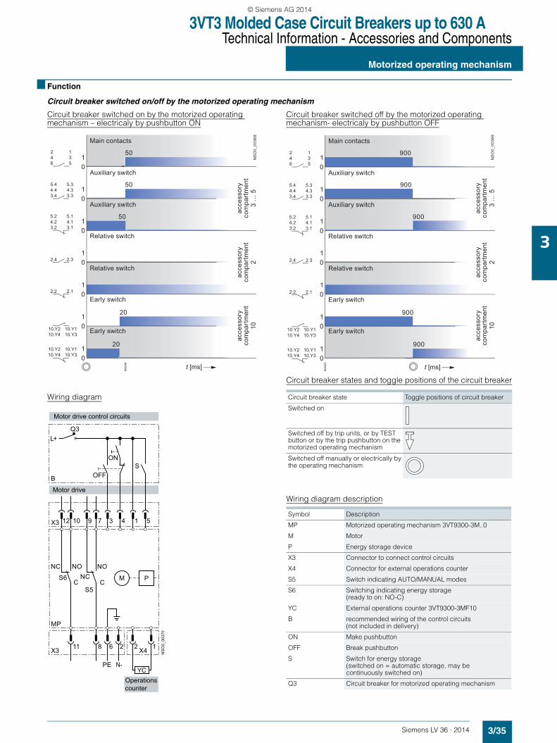
3VT3 Molded Case Circuit Breakers up to 630 ATechnical Information - Accessories and Components
Motorized operating mechanism
3/35Siemens LV 36 · 2014
3
■ Function
Circuit breaker switched on/off by the motorized operating mechanism
Circuit breaker switched on by the motorized operating mechanism – electricaly by pushbutton ON
Circuit breaker switched off by the motorized operating mechanism- electricaly by pushbutton OFF
Circuit breaker states and toggle positions of the circuit breaker
Wiring diagram
Wiring diagram description
50
50
50
20
01
01
01
01
01
01
01
t [ms]
20
NS
O0_
0036
8
246
135
5.44.43.4
5.34.33.3
5.24.23.2
5.14.13.1
2.4 2.3
2.2 2.1
10.Y210.Y4
10.Y110.Y3
10.Y210.Y4
10.Y110.Y3
Main contacts
Auxiliary switch
Auxiliary switch
Relative switch
Relative switch
Early switch
Early switch
acce
ssor
yco
mpa
rtm
ent
2
acce
ssor
yco
mpa
rtm
ent
3 …
5
acce
ssor
yco
mpa
rtm
ent
10
900
900
900
900
01
01
01
01
01
01
01
t [ms]
900
NS
O0_
0036
9
246
135
5.44.43.4
5.34.33.3
5.24.23.2
5.14.13.1
2.4 2.3
2.2 2.1
10.Y210.Y4
10.Y110.Y3
10.Y210.Y4
10.Y110.Y3
Main contacts
Auxiliary switch
Auxiliary switch
Relative switch
Relative switch
Early switch
Early switch
acce
ssor
yco
mpa
rtm
ent
2
acce
ssor
yco
mpa
rtm
ent
3 …
5
acce
ssor
yco
mpa
rtm
ent
10
X4
YC
3
6
4
2
1
2
5
1
X3
MP
S6C
X3
12 10
11
M P
NS
O0_
0037
0
B
PE N-
S5C
9 7
8
L+Q3
S
Operationscounter
Motor drive control circuits
Motor drive
ON
OFF
NCNC
NONO
Circuit breaker state Toggle positions of circuit breaker
Switched on
Switched off by trip units, or by TEST button or by the trip pushbutton on the motorized operating mechanism
Switched off manually or electrically by the operating mechanism
Symbol Description
MP Motorized operating mechanism 3VT9300-3M..0
M Motor
P Energy storage device
X3 Connector to connect control circuits
X4 Connector for external operations counter
S5 Switch indicating AUTO/MANUAL modes
S6 Switching indicating energy storage (ready to on: NO-C)
YC External operations counter 3VT9300-3MF10
B recommended wiring of the control circuits (not included in delivery)
ON Make pushbutton
OFF Break pushbutton
S Switch for energy storage(switched on = automatic storage, may be continuously switched on)
Q3 Circuit breaker for motorized operating mechanism
LV36_2014.book Seite 35 Freitag, 31. Januar 2014 4:36 16
© Siemens AG 2014

3VT3 Molded Case Circuit Breakers up to 630 ATechnical Information - Accessories and Components
Motorized operating mechanism
3/36 Siemens LV 36 · 2014
3
Tripping of the circuit breaker with a motorized operating mecha-nism by the trip unit (switch S – automatic spring charging)
Tripping of the circuit breaker with motorized operating mecha-nism by a shunt trip unit or undercurrent trip unit (switch S – automatic spring charging)
Wiring diagram
Circuit breaker switched on by motorized operating mechanism (electrical ON signal) and switched off by the shunt trip unit
Circuit breaker switched on by motorized operating mechanism (electrical ON signal) and switched off by undervoltage trip unit
20
20
20
30
20
30
20
650
650
30
01
01
01
01
01
01
01
t [ms]
650
650
NS
O0_
0052
7
246
135
3.4 3.3
3.2 3.1
2.4 2.3
2.2 2.1
1.4 1.3
1.2 1.1
Main contacts
Auxiliary switch
Auxiliary switch
Relative switch
Relative switch
Early switch
Early switch
acce
ssor
yco
mpa
rtm
ent
2
acce
ssor
yco
mpa
rtm
ent
3
acce
ssor
yco
mpa
rtm
ent
1
20
20
20
20
30 520
30 520
01
01
01
01
01 N
SO
0_00
242
t [ms]
246
135
3.4 3.3
3.2 3.1
2.4 2.3
2.2 2.1
acce
ssor
yco
mpa
rtm
ent
3
acce
ssor
yco
mpa
rtm
ent
2
Main contacts
Auxiliary switch
Auxiliary switch
Relative switch
Relative switch
JX4 D2
C2
D1
C1
YC
3
6
4
2
1
2
5
1
X3
MP
S6C
X3
12 10
11
M P U< U
NS
O0_
0037
1a
3VT9
300-
1U.0
0
3VT9
300-
1S.0
0
B
PE N-
S5C
9 7
8
L+Q3
S
N-
acc.c. No.10
Control circuit
Motor drive
ON
OFF
Operationscounter
NC NONC NO
or
JX4 D2
C 2
D1
C1
YC
3
6
4
2
1
2
5
1
X3
MP
S6C
X3
12 10
11
M P U< U
NS
O0_
0037
2a
3VT9
300-
1U.0
0
3VT9
300-
1S.0
0
B
PE
S5C
9 7
8
L+Q3
S
N-N-
Operationscounter
acc.c. No. 10
Motor drive control circuits
Motor drive
ON
OFF
or
NC NO
NC NO
LV36_2014.book Seite 36 Freitag, 31. Januar 2014 4:36 16
© Siemens AG 2014
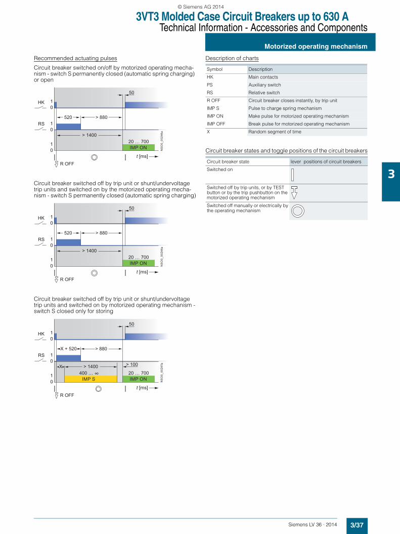
3VT3 Molded Case Circuit Breakers up to 630 ATechnical Information - Accessories and Components
Motorized operating mechanism
3/37Siemens LV 36 · 2014
3
Recommended actuating pulses
Circuit breaker switched on/off by motorized operating mecha-nism - switch S permanently closed (automatic spring charging) or open
Circuit breaker switched off by trip unit or shunt/undervoltage trip units and switched on by the motorized operating mecha-nism - switch S permanently closed (automatic spring charging)
Circuit breaker switched off by trip unit or shunt/undervoltage trip units and switched on by motorized operating mechanism -switch S closed only for storing
Description of charts
Circuit breaker states and toggle positions of the circuit breakersNS
O0_
0024
6at [ms]
10
10
10
HK
RS
R
520
20 … 700> 1400
50
> 880
OFF
IMP ON
NS
O0_
0024
6a
t [ms]
10
10
10
HK
RS
R
520
20 … 700> 1400
50
> 880
OFF
IMP ON
NS
O0_
0024
7a
t [ms]
10
10
10
HK
RS
R
X + 520
20 … 700> 1400X
50
400 … ∞
> 880
> 100
OFF
IMP ONIMP S
Symbol Description
HK Main contacts
PS Auxiliary switch
RS Relative switch
R OFF Circuit breaker closes instantly, by trip unit
IMP S Pulse to charge spring mechanism
IMP ON Make pulse for motorized operating mechanism
IMP OFF Break pulse for motorized operating mechanism
X Random segment of time
Circuit breaker state lever positions of circuit breakers
Switched on
Switched off by trip units, or by TEST button or by the trip pushbutton on the motorized operating mechanism
Switched off manually or electrically by the operating mechanism
LV36_2014.book Seite 37 Freitag, 31. Januar 2014 4:36 16
© Siemens AG 2014
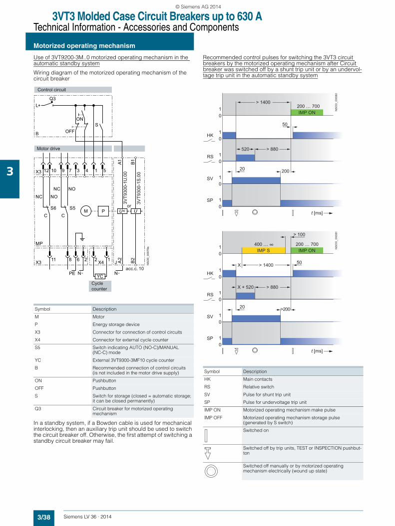
3VT3 Molded Case Circuit Breakers up to 630 ATechnical Information - Accessories and Components
Motorized operating mechanism
3/38 Siemens LV 36 · 2014
3
Use of 3VT9200-3M..0 motorized operating mechanism in the automatic standby system
Wiring diagram of the motorized operating mechanism of the circuit breaker
In a standby system, if a Bowden cable is used for mechanical interlocking, then an auxiliary trip unit should be used to switch the circuit breaker off. Otherwise, the first attempt of switching a standby circuit breaker may fail.
Recommended control pulses for switching the 3VT3 circuit breakers by the motorized operating mechanism after Circuit breaker was switched off by a shunt trip unit or by an undervol-tage trip unit in the automatic standby system
Symbol Description
M Motor
P Energy storage device
X3 Connector for connection of control circuits
X4 Connector for external cycle counter
S5 Switch indicating AUTO (NO-C)/MANUAL (NC-C) mode
YC External 3VT9300-3MF10 cycle counter
B Recommended connection of control circuits (is not included in the motor drive supply)
ON Pushbutton
OFF Pushbutton
S Switch for storage (closed = automatic storage; it can be closed permanently)
Q3 Circuit breaker for motorized operating mechanism
JX4 A2
B2
A1 B1
YC
3
6
4
2
1
2
5
1
X3
MP
S6C
X3
12 10
11
M P U< U
NS
O0_
0007
9a
3VT9
300-
1U.0
0
3VT9
300-
1S.0
0B
PE
S5C
9 7
8
L+Q3
S
N-N-
Cyclecounter
acc.c. 10
Control circuit
Motor drive
ON
OFF
or
NC NO
NC NO
Symbol Description
HK Main contacts
RS Relative switch
SV Pulse for shunt trip unit
SP Pulse for undervoltage trip unit
IMP ON Motorized operating mechanism make pulse
IMP OFF Motorized operating mechanism storage pulse (generated by S switch)
Switched on
Switched off by trip units, TEST or INSPECTION pushbut-ton
Switched off manually or by motorized operating mechanism electrically (wound up state)
20
01
01
01
01
01 N
SO
0_00
080
t [ms]
HK
SP
SV
RS
200
200 … 700
> 880520
50
> 1400
IMP ON
20
01
01
01
01
01 N
SO
0_00
081
t [ms]
HK
SP
SV
RS
>200
> 100
200 … 700400 … ∞
> 880X + 520
50X > 1400
IMP ONIMP S
LV36_2014.book Seite 38 Freitag, 31. Januar 2014 4:36 16
© Siemens AG 2014
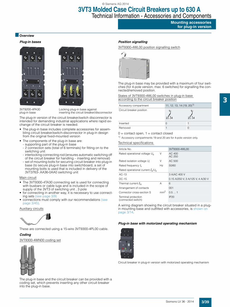
3VT3 Molded Case Circuit Breakers up to 630 ATechnical Information - Accessories and Components
Mounting accessoriesfor plug-in version
3/39Siemens LV 36 · 2014
3
■ Overview
Plug-in bases
3VT9200-4PA30 Locking plug-in base against plug-in base inserting the circuit breaker/disconnector
The plug-in version of the circuit breaker/switch disconnector is intended for demanding industrial applications where rapid ex-change of the circuit breaker is needed.• The plug-in base includes complete accessories for assem-
bling circuit breaker/switch-disconnector in plug-in design from the original fixed-mounted version
• The components of the plug-in base are:- supporting part of the plug-in base - 2 connection sets (total of 6 terminals) for fitting on to the
switching unit- interlocking connecting rod (ensures automatic switching off
of the circuit breaker for handling – inserting and removal)- set of mounting bolts for securing circuit breaker into plug-in
base (to secure plug-in base into switchboard, a set of mounting bolts is used that is included in delivery of the3VT3763-.AA36-0AA0 switching unit
Main circuit• The 3VT9300-4TA30 connecting set is used for connecting
with busbars or cable lugs and is included in the scope of supply of the 3VT3 of switching unit , 3 pole
• for connecting in another way, it is necessary to use connect-ing sets (see page 3/9)
• connections must comply with our recommendations (see page 3/45).
Auxiliary circuits
These are connected using a 15-wire 3VT9300-4PL00 cable.
Coding
3VT9300-4WN00 coding set
The plug-in base and the circuit breaker can be provided with a coding set, which prevents inserting any other circuit breaker into the plug-in base.
Position signalling
3VT9300-4WL00 position signalling switch
The plug-in base may be provided with a maximum of four swit-ches (for 4-pole version, max. 6 switches) for signalling the con-nected/removed position.
States of 3VT9300-4WL00 switches in plug-in base according to the circuit breaker position
0 = contact open, 1 = contact closed1) Accessory compartments 19 and 20 are for 4-pole version only.
Technical specifications
A wiring diagram showing the circuit breaker situated in a plug-in mounting base and outfitted with accessories, is shown on page 3/14.
Plug-in base with motorized operating mechanism
Circuit breaker in plug-in version with motorized operating mechanism
Accessory compartment 11, 12, 13, 14 (19, 20)1)
Circuit breaker position
Inserted 0 1
Removed 1 0
Article No. 3VT9300-4WL00
Rated operational voltage Ue V AC 400AC 250
Rated isolation voltage Ui V AC 500
Rated frequency fn Hz 50/60
Rated operational current Ie/Ue
AC-13 3 A/AC 400 V
DC-15 0.15 A/250 V, 3 A/125 V, 4 A/30 V
Thermal current Ith A 6
Arrangement of contacts 001
Connector cross-section S mm2 0.5 ... 1
Terminal protection(connected switch)
IP20
2
1
4 2
1
4
LV36_2014.book Seite 39 Freitag, 31. Januar 2014 4:36 16
© Siemens AG 2014

3VT3 Molded Case Circuit Breakers up to 630 ATechnical Information - Accessories and ComponentsMounting accessoriesfor plug-in version
3/40 Siemens LV 36 · 2014
3
Recommended wiring of the circuit breaker in plug-in design with motorized operating mechanism
Recommended process of manipulationAfter every manipulation with circuit breaker in plug-in designit is necessary to accomplish the operations in following se-quence, after repeated insertation into the plug-in device:
Unplugging the circuit breaker with motorized operating mechanism• Each time before removing the circuit breaker, we recommend
turning first of all the AUTO/MANUAL switch on the motorized operating mechanism to the MANUAL position
• More operating information is available in the operating instructions
• Not adhering to this procedure or failing to follow the recom-mended wiring, could mean that the circuit breaker will not successfully switch on at the first attempt.
1) press the switch off button (red) on the motor operating mechanism
2) press the switch on button (green) on the motor operating mechanism
L+Q3
X4
YC
3
6
4
2
1
2
5
1
X3
MP
C
X3
12 10
11
M P
SB
PE N-
S5C
9 7
8
NS
O0_
0035
0
Motor drive control circuits
Operatingcounter
Motor drive
C NO
S6 NCNO
ON
OFF
N
1 2
Symbol Description
MP 3VT9300-3M..0 motorized operating mechanism
M Motor
P Energy storage device
X3 Terminal strip to connect control circuits
X4 Terminal strip for external operations counter
S5 Switch indicating AUTO (NO-C)/MANUAL (NC-C) modes
S6 Switch to indicate full storage (ready to switch on: NO-C)
YC External operations counter 3VT9300-3MF10
B Recommended wiring of the control circuits (control circuits not included in motorized operating mechanism delivery)
ON Make pushbutton
OFF Break pushbutton
S Switch to store energy
Q3 Circuit breaker for motorized operating mechanismAC 24V 5SX4104-7AC 48V 5SX4104-7AC 110V 5SX4104-7AC 230V 5SX4102-7DC 24V 5SX5104-7DC 48V 5SX5104-7DC 110V 5SX5104-7DC 220V 5SX5102-7
LV36_2014.book Seite 40 Freitag, 31. Januar 2014 4:36 16
© Siemens AG 2014

3VT3 Molded Case Circuit Breakers up to 630 ATechnical Information - Accessories and Components
Mounting accessoriesfor plug-in version
3/41Siemens LV 36 · 2014
3
Changes in states of switches when inserting and withdrawing the circuit breaker
0 = contact open, 1 = contact closed1) Accessory compartments 4, 5, 6 are for 4-pole version only.
State of circuit breaker before removing State of switches before removing inserted position →
State of switches after removingwithdrawn position
Accessory compartment 1 2 3, 4, 5 (6 ... 9)1)
1 2 3, 4, 5 (6 ... 9)1)
Leve
r p
ositi
on o
f th
e ci
rcui
t bre
aker
Sta
te o
f the
m
ain
cont
acts 3V
T930
0-2A
C10
3VT9
300-
2AH
10
3VT9
300-
2AC
10
3VT9
300-
2AH
10
3VT9
300-
2AC
10
3VT9
300-
2AH
10
3VT9
300-
2AC
10
3VT9
300-
2AH
10
3VT9
300-
2AC
10
3VT9
300-
2AH
10
3VT9
300-
2AC
10
3VT9
300-
2AH
10
Switched on 1 1 0 0 1 1 0 1 0 1 0 0 1
Manually switched off or switched off by motorized operating mechanism
0 1 0 0 1 0 1 1 0 1 0 0 1
Switched off by trip units 0 0 1 1 0 0 1 0 1 1 0 0 1
Switched off from switched-on state: by means of auxiliary trip unit, TEST pushbutton or by OFF pushbutton located on the motorized operating mechanism
0 1 0 1 0 0 1 1 0 1 0 0 1
4
3
2
1
4
3
2
1
4
3
2
1
4
3
2
1
4
3
2
1
4
3
2
1
LV36_2014.book Seite 41 Freitag, 31. Januar 2014 4:36 16
© Siemens AG 2014

3VT3 Molded Case Circuit Breakers up to 630 ATechnical Information - Accessories and ComponentsMounting accessoriesfor withdrawable version
3/42 Siemens LV 36 · 2014
3
■ Design
Withdrawable version mounting base
Circuit breaker installed 3VT9300-4WA30 in withdrawable version base withdrawable version base
The withdrawable version of the circuit breaker/switch-discon-nector is intended for demanding industrial applications where rapid exchange of the circuit breaker and frequent checking of the circuit are needed.• The withdrawable version base includes all parts needed to
convert a circuit breaker or switch disconnector from fixed-mounted version to withdrawable version.
• The components of the withdrawable version are:- withdrawable version base- 2 movable side plates- 2 connection sets (total of 6 terminals) for fitting onto the
switching unit- interlocking connecting rod (ensures automatic switching off
of the circuit breaker when handling, inserting and withdraw-ing)
- a set of mounting bolts needed to fasten the withdrawable version mounting base into the switchboard
Main circuit• The 3VT9300-4TA30 connecting set is used for connecting
with busbars or cable lugs and is included in delivery of the 3VT3763-.AA36-0AA0 switching unit
• For connecting in another way, it is necessary to use connect-ing sets (see page 3/9)
• The type of connections must comply with our recommenda-tions (see page 3/45).
Auxiliary circuits
These are connected using the 3VT9300-4PL00 15-wire cable.
Coding
3VT9300-4WN00 coding set
The withdrawable version mounting base and the circuit breaker can be provided with coding set, which prevents inserting ano-ther circuit breaker into the withdrawable version mounting base.
Position signalling
3VT9300-4WL00 position signalling switch
The withdrawable version can be provided with switches for si-gnalling the position of the circuit breaker, see table.
Technical specifications
For wiring diagram of the circuit breaker in withdrawable device with accessories, see page 3/14.
States of 3VT9300-4WL00 switches in withdrawable version according to circuit breaker and lockout positions
0 = contact open, 1 = contact closed1) Accessory compartments 19 and 20 are for 4-pole version only.
• Operating state is always in locked-out position• In locked-out position, it is possible to lock the withdrawable
device, so that the circuit breaker cannot be switched on (for more detailed information, see "Advantages and enhanced safety for operator").
Article No. 3VT9300-4WL00
Rated operational voltage Ue V AC 400AC 250
Rated isolation voltage Ui V AC 500
Rated frequency fn Hz 50/60
Rated operational current Ie/Ue
AC-13 3 A/AC 400 V
DC-15 0.15 A/DC 250 V, 3 A/DC 125 V, 4 A/DC 30 V
Thermal current Ith A 6
Arrangement of contacts 001
Connector cross-section S mm2 0.5 ... 1
Terminal protection(connected switch)
IP20
State of switch Accessory compartment
11 ... 14 (19, 20)1)
15,17(19, 20)1)
16, 18
Circuit breaker and lockout position
Inserted and unlocked 0 1 1 0 0 1
0 1 1 0 1 0
Withdrawn and unlocked 1 0 0 1 0 1
1 0 0 1 1 0
Removed and unlocked 1 0 1 0 0 1
1 0 1 0 1 0
2
1
4 2
1
4 2
1
4
LV36_2014.book Seite 42 Freitag, 31. Januar 2014 4:36 16
© Siemens AG 2014

3VT3 Molded Case Circuit Breakers up to 630 ATechnical Information - Accessories and Components
Mounting accessoriesfor withdrawable version
3/43Siemens LV 36 · 2014
3
Locking
Locking the circuit breaker Locking the withdrawable version in withdrawable version base against inserting the circuit base against tampering breaker
Withdrawable version with motorized operating mechanism
Recommended wiring of the circuit breaker in withdrawableversion with motorized operating mechanism
Wiring diagram description
Inserting and withdrawing the circuit breaker with motorized operating mechanism• Each time before inserting or withdrawing the circuit breaker,
we recommend placing the AUTO/MANUAL switch on the mo-torized operating mechanism to MANUAL position
• More operating information is available in the operating instructions
• Not adhering to this procedure or failing to follow the recom-mended wiring could mean that the circuit breaker will not successfully turn on at the first attempt.
L+Q3
X4
YC
3
6
4
2
1
2
5
1
X3
MP
C
X3
12 10
11
M P
SB
PE N-
S5C
9 7
8
NS
O0_
0035
0
Motor drive control circuits
Operatingcounter
Motor drive
C NO
S6 NCNO
ON
OFF
N
Symbol Description
MP 3VT9300-3M..0 motorized operating mechanism
M Motor
P Energy storage device
X3 Terminal strip to connect control circuits
X4 Terminal strip for external operations counter
S5 Switch indicating AUTO (NO-C)/MANUAL (NC-C) modes
S6 Switch to indicate full storage (ready to switch on: NO-C)
YC External operations counter 3VT9300-3MF10
B Recommended wiring of the control circuits (control circuits not included in motorized operating mechanism delivery)
ON Make pushbutton
OFF Break pushbutton
S Switch to charge spring mechanism
Q3 Circuit breaker for motorized operating mechanismAC 24V 5SX4104-7AC 48V 5SX4104-7AC 110V 5SX4104-7AC 230V 5SX4102-7DC 24V 5SX5104-7DC 48V 5SX5104-7DC 110V 5SX5104-7DC 220V 5SX5102-7
LV36_2014.book Seite 43 Freitag, 31. Januar 2014 4:36 16
© Siemens AG 2014
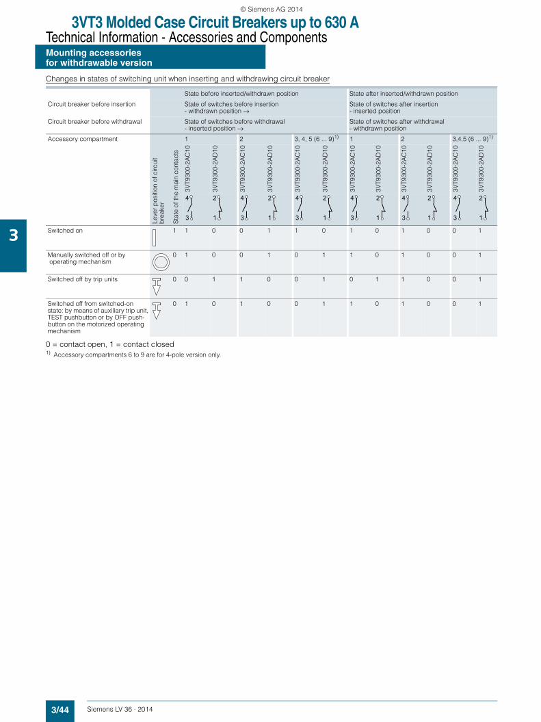
3VT3 Molded Case Circuit Breakers up to 630 ATechnical Information - Accessories and ComponentsMounting accessoriesfor withdrawable version
3/44 Siemens LV 36 · 2014
3
Changes in states of switching unit when inserting and withdrawing circuit breaker
0 = contact open, 1 = contact closed1) Accessory compartments 6 to 9 are for 4-pole version only.
State before inserted/withdrawn position State after inserted/withdrawn position
Circuit breaker before insertion State of switches before insertion- withdrawn position →
State of switches after insertion- inserted position
Circuit breaker before withdrawal State of switches before withdrawal- inserted position →
State of switches after withdrawal- withdrawn position
Accessory compartment
Leve
r p
ositi
on o
f circ
uit
bre
aker
Sta
te o
f the
mai
n co
ntac
ts
1 2 3, 4, 5 (6 ... 9)1) 1 2 3,4,5 (6 ... 9)1)
3VT9
300-
2AC
10
3VT9
300-
2AD
10
3VT9
300-
2AC
10
3VT9
300-
2AD
10
3VT9
300-
2AC
10
3VT9
300-
2AD
10
3VT9
300-
2AC
10
3VT9
300-
2AD
10
3VT9
300-
2AC
10
3VT9
300-
2AD
10
3VT9
300-
2AC
10
3VT9
300-
2AD
10
Switched on 1 1 0 0 1 1 0 1 0 1 0 0 1
Manually switched off or by operating mechanism
0 1 0 0 1 0 1 1 0 1 0 0 1
Switched off by trip units 0 0 1 1 0 0 1 0 1 1 0 0 1
Switched off from switched-on state: by means of auxiliary trip unit, TEST pushbutton or by OFF push-button on the motorized operating mechanism
0 1 0 1 0 0 1 1 0 1 0 0 1
4
3
2
1
4
3
2
1
4
3
2
1
4
3
2
1
4
3
2
1
4
3
2
1
LV36_2014.book Seite 44 Freitag, 31. Januar 2014 4:36 16
© Siemens AG 2014

3VT3 Molded Case Circuit Breakers up to 630 ATechnical Information - Accessories and Components
Insulating barriers and terminal covers
3/45Siemens LV 36 · 2014
3
■ Overview
Use of insulating barriers and terminal covers for circuitbreakers and switch disconnectors
Fixed-mounted version
Front connection• Terminals 1, 3, 5
- If Ue = AC 415 V, it is necessary to use 3VT9300-8CE30 insulating barriers or 3VT9300-8CB30 terminal covers.
- For the connection of the main circuit to terminals 1, 3, 5, in-sulated conductors, flexibars or rear connection terminals are not used. It is necessary to use 3VT9300-8CE30 insulat-ing barriers or 3VT9300-8CB30 terminal cover.
Deionization Spaces
• Terminals 2, 4, 6- If the circuit breaker/switch disconnector is connected to the
the power supply with terminals 2, 4, 6 and if Ue = AC 415 V, it is necessary to use 3VT9300-8CE30 insulating barriers or a 3VT9300-8CB30 terminal cover.
- If insulated conductors are not used for connecting the main circuit to terminals 2, 4, 6, and flexibars or rear connections are not used, then it is necessary to use 3VT9300-8CE30 in-sulating barriers or 3VT9300-8CB30 terminal covers.
Rear connection• Neither insulating barriers nor terminal covers have to be
used.
Plug-in and withdrawable versions
Neither insulating barriers nor terminal covers have to be used.
2 4 6
TEST
ON
OFF
2 4 6
TEST
ON
OFF
2 4 6
1 3 5
275
20
TEST
ON
OFF
B = 0
NS
O0_
0025
9a
AA
1
D
A2
C = 01 3 51 3 5
B = 105 C = 80
B = 20 140 140 140
100
… 1
50
B = 20
3VT9300-8CE30
1 1
1
A Minimum distance between the circuit breaker/switch-disconnector and uninsulated earthed wall (applicable for con-necting using insulated conductors, cables, flexibars or with rear connection)
A1 Minimum insulation length of bare conductors (using 3VT9300-8CE30 insulating barriers from 100 mm to max. 150 mm, or by adding additional insulation for the conductors with barriers to obtain at least A1 value)
A2 Minimum distance:• between the circuit breaker/switch-disconnector and uninsula-
ted earthed wall (applicable for uninsulated conductors and busbars)
• between the circuit breaker/switch-disconnector and busbar• between two circuit breaker/switch-disconnectors situated ver-
tically above one another• between uninsulated connections of two circuit breakers/
switch-disconnectors above one another
B, C Minimum distance between the circuit breaker/switch-discon-nector and uninsulated earthed wall
D Minimum distance between uninsulated conductors
LV36_2014.book Seite 45 Freitag, 31. Januar 2014 4:36 16
© Siemens AG 2014
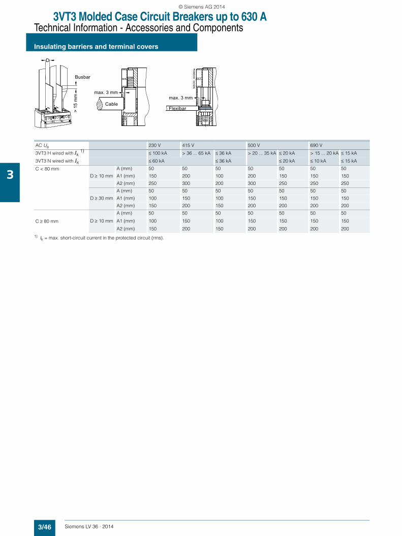
3VT3 Molded Case Circuit Breakers up to 630 ATechnical Information - Accessories and Components
Insulating barriers and terminal covers
3/46 Siemens LV 36 · 2014
3
1) Ik = max. short-circuit current in the protected circuit (rms).
D
> 15
mm
NS
O0_
0026
0a
Cable
Busbar
max. 3 mmmax. 3 mm
Flexibar
AC Ue 230 V 415 V 500 V 690 V
3VT3 H wired with Ik 1) ≤ 100 kA > 36 ... 65 kA ≤ 36 kA > 20 ... 35 kA ≤ 20 kA > 15 ... 20 kA ≤ 15 kA
3VT3 N wired with Ik ≤ 60 kA ≤ 36 kA ≤ 20 kA ≤ 10 kA ≤ 15 kA
C < 80 mm A (mm) 50 50 50 50 50 50 50
D ≥ 10 mm A1 (mm) 150 200 100 200 150 150 150
A2 (mm) 250 300 200 300 250 250 250
A (mm) 50 50 50 50 50 50 50
D ≥ 30 mm A1 (mm) 100 150 100 150 150 150 150
A2 (mm) 150 200 150 200 200 200 200
A (mm) 50 50 50 50 50 50 50
C ≥ 80 mm D ≥ 10 mm A1 (mm) 100 150 100 150 150 150 150
A2 (mm) 150 200 150 200 200 200 200
LV36_2014.book Seite 46 Freitag, 31. Januar 2014 4:36 16
© Siemens AG 2014
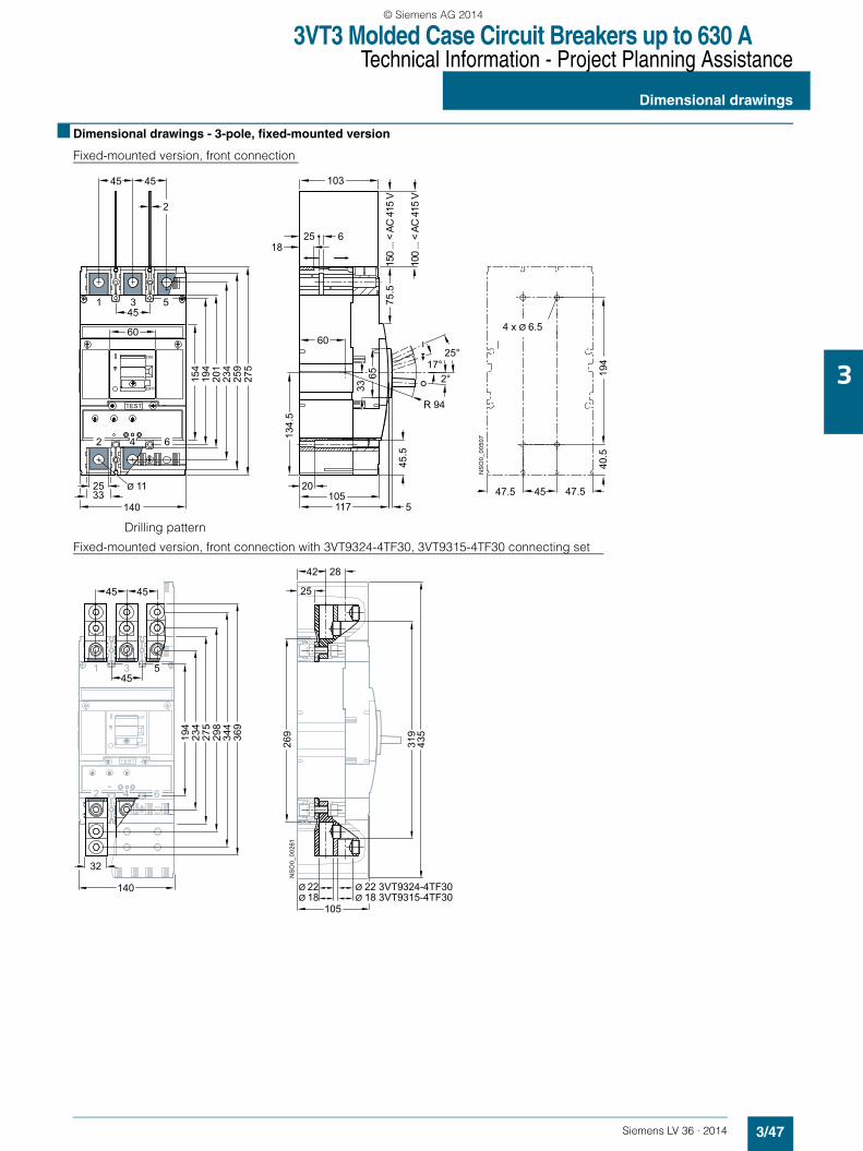
3VT3 Molded Case Circuit Breakers up to 630 ATechnical Information - Project Planning Assistance
Dimensional drawings
3/47Siemens LV 36 · 2014
3
■ Dimensional drawings - 3-pole, fixed-mounted version
Fixed-mounted version, front connection
Drilling pattern
Fixed-mounted version, front connection with 3VT9324-4TF30, 3VT9315-4TF30 connecting set
1 3 5
25 Ø 11
TEST
194
154
60
45
33140
ON
OFF
62 4
234
201
259
275
45 45
2
1825 6
60
20105
117 5
6533
NS
O0_
0050
7
45
194
103
47.5
75.5
134.
5
45.5
47.5
40.5
4 x Ø 6.5
17°2°
25°
R 9410
0 ...
< A
C 4
15 V
150
... <
AC
415
V
NS
O0_
0026
1
1 3 5
TEST
234
194
298
344
369
ON
OFF
62 4
32
45
45
45
42 28
25
319
435
269
105
140
275
Ø 22 Ø 22 3VT9324-4TF30Ø 18 Ø 18 3VT9315-4TF30
LV36_2014.book Seite 47 Freitag, 31. Januar 2014 4:36 16
© Siemens AG 2014
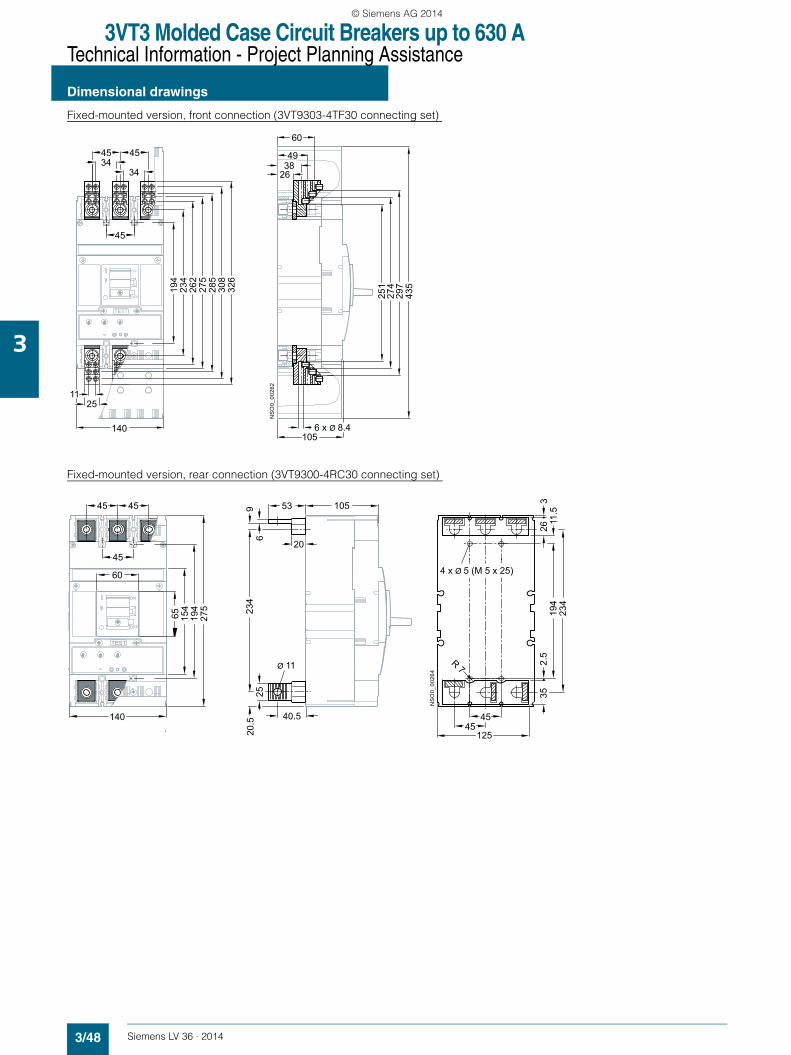
3VT3 Molded Case Circuit Breakers up to 630 ATechnical Information - Project Planning Assistance
Dimensional drawings
3/48 Siemens LV 36 · 2014
3
Fixed-mounted version, front connection (3VT9303-4TF30 connecting set)
Fixed-mounted version, rear connection (3VT9300-4RC30 connecting set)
140
TEST
194
234
262
275
285
308
326
ON
OFF
2511
4534
45
45
34
NS
O0_
0026
2
263849
251
274
297
60
105
435
6 x Ø 8.4
140
275
TEST
194
154
65
60
45
ON
OFF
105
NS
O0_
0026
4
234
25
Ø 11
20
5396
R 7
45
194
326
234
45125
4 x Ø 5 (M 5 x 25)
35
20.5 40.5
2.5
11.54545
LV36_2014.book Seite 48 Freitag, 31. Januar 2014 4:36 16
© Siemens AG 2014
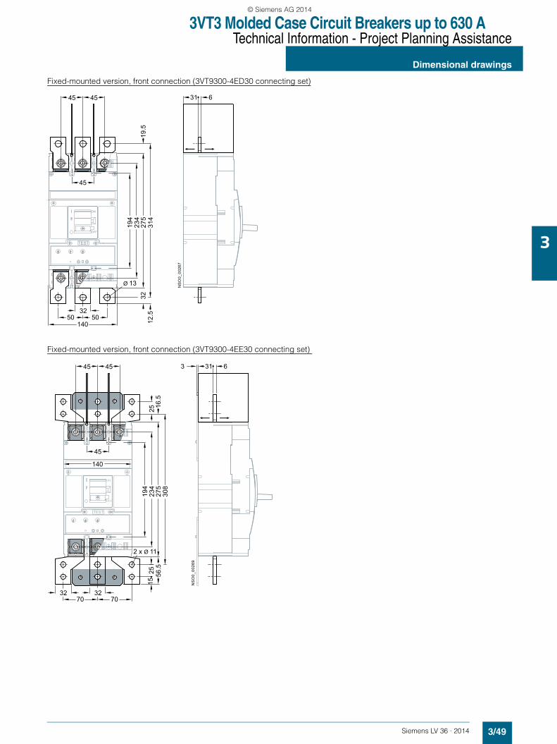
3VT3 Molded Case Circuit Breakers up to 630 ATechnical Information - Project Planning Assistance
Dimensional drawings
3/49Siemens LV 36 · 2014
3
Fixed-mounted version, front connection (3VT9300-4ED30 connecting set)
Fixed-mounted version, front connection (3VT9300-4EE30 connecting set)
275
TEST
45
ON
OFF
45 45
32
140 12.5
194
314
234
5050
631
NS
O0_
0026
7
3219
.5
Ø 13
275
TEST
140
45
ON
OFF
45 45
32 3270 70
2 x Ø 11
1525
194
308
234
3 631
NS
O0_
0026
9
2556
.516
.5
LV36_2014.book Seite 49 Freitag, 31. Januar 2014 4:36 16
© Siemens AG 2014
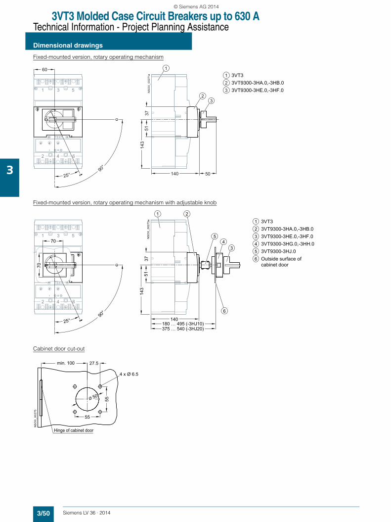
3VT3 Molded Case Circuit Breakers up to 630 ATechnical Information - Project Planning Assistance
Dimensional drawings
3/50 Siemens LV 36 · 2014
3
Fixed-mounted version, rotary operating mechanism
Fixed-mounted version, rotary operating mechanism with adjustable knob
Cabinet door cut-out
NS
O0_
0027
1a
1 3 5
2 4 6
TEST
60
90°
25° 140 50
5114
337
3VT3 3VT9300-3HA.0,-3HB.03VT9300-3HE.0,-3HF.0
123
1
23
NS
O0_
0027
3a
1 3 5
2 4 6
TEST
90°
25° 140
5114
337
70
180 … 495 (-3HJ10)375 … 540 (-3HJ20)
70
21
34
5
6
3VT3 3VT9300-3HA.0,-3HB.03VT9300-3HE.0,-3HF.0 3VT9300-3HG.0,-3HH.03VT9300-3HJ.0
123456 Outside surface of
cabinet door
NS
O0_
0027
5
Ø 50
55
55
27.5
4 x Ø 6.5
min. 100
Hinge of cabinet door
LV36_2014.book Seite 50 Freitag, 31. Januar 2014 4:36 16
© Siemens AG 2014
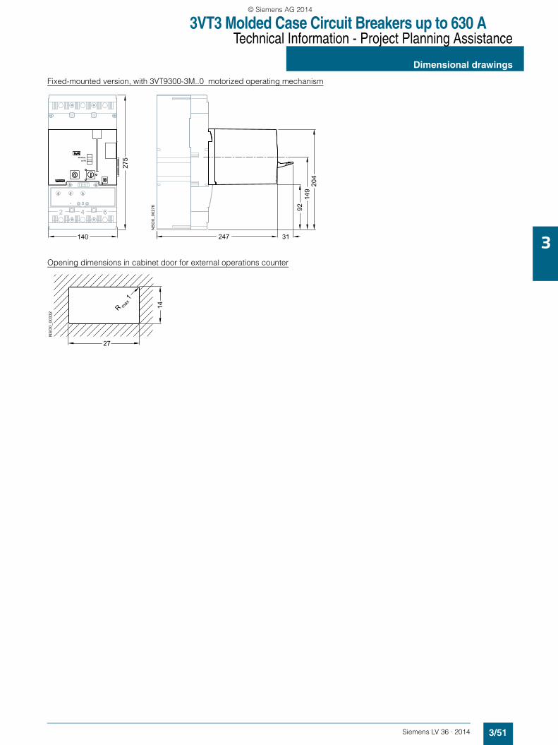
3VT3 Molded Case Circuit Breakers up to 630 ATechnical Information - Project Planning Assistance
Dimensional drawings
3/51Siemens LV 36 · 2014
3
Fixed-mounted version, with 3VT9300-3M..0 motorized operating mechanism
Opening dimensions in cabinet door for external operations counter
247 31
9214
920
4
NS
O0_
0027
6
2 4 6
TEST
AUTO
MANUAL
140
275
NS
O0_
0033
2 14
27
R 1
max
LV36_2014.book Seite 51 Freitag, 31. Januar 2014 4:36 16
© Siemens AG 2014

3VT3 Molded Case Circuit Breakers up to 630 ATechnical Information - Project Planning Assistance
Dimensional drawings
3/52 Siemens LV 36 · 2014
3
■ Dimensional drawings - 3-pole, plug-in version
3VT9300-4PA30 plug-in base Drilling patterns
Plug-in version, 3VT9300-8CB30 motorized operating mechanism
NS
O0_
0027
9
166
194
234
277
342
317
284
Ø 4+8 mm
L R
2
25
45
45 45
33Ø 11
140
4 6
1 3 5
358
179
96
3520
2026
105
1825 6
9616
6
277
45 45
40.5
40.5
47.5 47.5
4 x Ø 6.5
4 x Ø 6.5
518
1 3 5
2 4 6
L R
Ø 4+8 mm
140
NS
O0_
0028
3
3570
103
105
LV36_2014.book Seite 52 Freitag, 31. Januar 2014 4:36 16
© Siemens AG 2014

3VT3 Molded Case Circuit Breakers up to 630 ATechnical Information - Project Planning Assistance
Dimensional drawings
3/53Siemens LV 36 · 2014
3
Plug-in version
Plug-in version, rear connection with 3VT9300-4RC30 connecting set
Drilling pattern
140
358
TEST
ON
OFF
105140
157187
NS
O0_
0028
5
TEST
ON
OFF
317
25
Ø 11
20
5396
105
963
5835
45
317
166
6726
3
45125N
SO
0_00
287
20.5 40.5
4 x Ø 6.5
47.5
LV36_2014.book Seite 53 Freitag, 31. Januar 2014 4:36 16
© Siemens AG 2014

3VT3 Molded Case Circuit Breakers up to 630 ATechnical Information - Project Planning Assistance
Dimensional drawings
3/54 Siemens LV 36 · 2014
3
Plug-in version, with rotary operating mechanism
Plug-in version, with 3VT9300-3M..0 motorized operating mechanism
TEST
175225
NS
O0_
0029
0
1 3 5
2 4 6
TEST
Ø 4,3 max.
AUTO
MANUAL
NS
O0_
0029
2
282 31
LV36_2014.book Seite 54 Freitag, 31. Januar 2014 4:36 16
© Siemens AG 2014
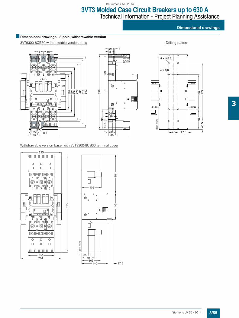
3VT3 Molded Case Circuit Breakers up to 630 ATechnical Information - Project Planning Assistance
Dimensional drawings
3/55Siemens LV 36 · 2014
3
■ Dimensional drawings - 3-pole, withdrawable version
3VT9300-8CB30 withdrawable version base Drilling pattern
Withdrawable version base, with 3VT9300-8CB30 terminal cover
NS
O0_
0029
8
166
194
234
277
342
317
284
Ø 4+8 mm
L R
2
25
45
45 45
33Ø 11
4 6
1 3 5
358
179
96
3520
2026
1825 6
9616
6
45
40.5
4 x Ø 6.5
4 x Ø 6.5
47.5
277
40.5
518
1 3 5
2 4 6
L R
Ø 4+8 mm
215
140214
NS
O0_
0030
2
140
204
3570
103140
105
27.5
LV36_2014.book Seite 55 Freitag, 31. Januar 2014 4:36 16
© Siemens AG 2014
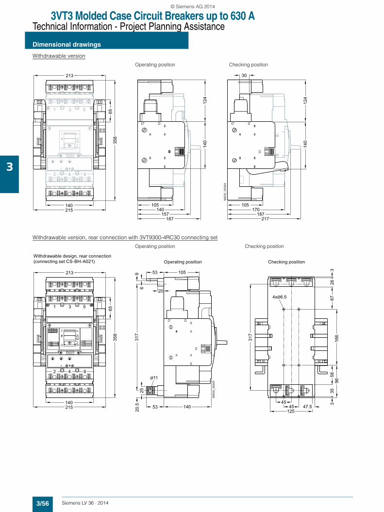
3VT3 Molded Case Circuit Breakers up to 630 ATechnical Information - Project Planning Assistance
Dimensional drawings
3/56 Siemens LV 36 · 2014
3
Withdrawable version
Operating position Checking position
Withdrawable version, rear connection with 3VT9300-4RC30 connecting set
Operating position Checking position
1 3 5
140
213
65
2 4 6
358
TEST
215
ON
OFF
105140
157
140
124
140
124
30
NS
O0_
0030
4187
105170
187217
1 3 5
140
213
65
2 4 6
358
TEST
215
ON
OFFSPSVPS PS
PSPSPS
963
5835
317
140
105
25
53
Ø11
20
5396
45
317
166
6726
3
45125
NS
O0_
0030
7
Checking positionOperating positionWithdrawable design, rear connection (connecting set CS-BH-A021)
4xØ6.5
20.5 47.5
LV36_2014.book Seite 56 Freitag, 31. Januar 2014 4:36 16
© Siemens AG 2014
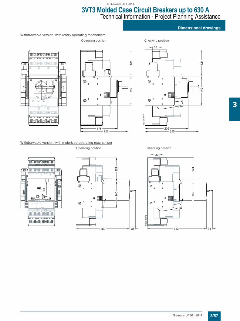
3VT3 Molded Case Circuit Breakers up to 630 ATechnical Information - Project Planning Assistance
Dimensional drawings
3/57Siemens LV 36 · 2014
3
Withdrawable version, with rotary operating mechanism
Operating position Checking position
Withdrawable version, with motorized operating mechanism
Operating position Checking position
175225
140
205
TEST
25512
4
140
124
30
NS
O0_
0030
9
282 31
140
312
124
30
31
140
124
NS
O0_
0031
2
1 3 5
2 4 6
TEST
Ø 4,3 max.
AUTO
MANUAL
LV36_2014.book Seite 57 Freitag, 31. Januar 2014 4:36 16
© Siemens AG 2014
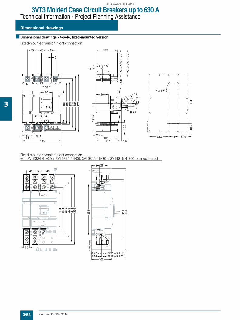
3VT3 Molded Case Circuit Breakers up to 630 ATechnical Information - Project Planning Assistance
Dimensional drawings
3/58 Siemens LV 36 · 2014
3
■ Dimensional drawings - 4-pole, fixed-mounted version
Fixed-mounted version, front connection
Fixed-mounted version, front connection with 3VT9324-4TF30 + 3VT9324-4TF00, 3VT9315-4TF30 + 3VT9315-4TF00 connecting set
N 1 3 5
25 Ø 11
TEST
194
154
60
45
33185
ON
OFF
62N 4
234
201
259
275
45 45 45
2
1825 6
150
... >
AC
415
V
60
17°2°
20105
117 5
65
100
... <
AC
415
V
33
NS
O0_
0031
9
45
194
103
75.5
134.
5
45.5
47.592.5
40.5
4 x Ø 6.5
25°
R 94
NS
O0_
0032
2
TEST
194
234
298
344
369
ON
OFF
32
45
45
45
42 28
319
435
269
105
275
45
Ø 18 Ø 18 (-3HJ20)
25
Ø 22 Ø 22 (-3HJ10)
LV36_2014.book Seite 58 Freitag, 31. Januar 2014 4:36 16
© Siemens AG 2014

3VT3 Molded Case Circuit Breakers up to 630 ATechnical Information - Project Planning Assistance
Dimensional drawings
3/59Siemens LV 36 · 2014
3
Fixed-mounted version, front connection with 3VT9303-4TF30 + 3VT9303-4TF00 connecting set
Fixed-mounted version, rear connection with 3VT9300-4RC30 + 3VT9300-4RC00 connecting set
NS
O0_
0032
4
185
TEST
194
234
262
275
285
308
326
ON
OFF
25
26
11
45 45
45
45
38 11
11
251
274
297
10543
56 x Ø 8.5
185
275
TEST
194
154
65
60
45
ON
OFF
105
NS
O0_
0032
6
234
25
Ø 11
20
5396
35
R 7
45 40
194
326
234
4517020
.5 40.5
2.5
7.5
4 x Ø 6.5
11.5
LV36_2014.book Seite 59 Freitag, 31. Januar 2014 4:36 16
© Siemens AG 2014

3VT3 Molded Case Circuit Breakers up to 630 ATechnical Information - Project Planning Assistance
Dimensional drawings
3/60 Siemens LV 36 · 2014
3
Fixed-mounted version, with rotary operating mechanism
Fixed-mounted version, with door-coupling operating mechanism
Cabinet door cut-out
NS
O0_
0027
2
140 50
5114
337
3VT3 3VT9300-3HA.0,-3HB.03VT9300-3HE.0,-3HF.0
123
1
23
1 3 5
2 4 6
TEST
90°
25°
105
N
N
NS
O0_
0027
4
1 3 5
2 4 6
TEST
90°
25° 140
5114
337
70
180 … 495 (-3HJ10)375 … 540 (-3HJ20)
70N
N
3VT3 3VT9300-3HA.0,-3HB.03VT9300-3HE.0,-3HF.0 3VT9300-3HG.0,-3HH.03VT9300-3HJ.0
123456
2
34
5
6
1
Outside surface ofcabinet door
NS
O0_
0032
9
Ø 50
55
55
27.5
4 x Ø 6.5
min. 145
Hinge of cabinet door
LV36_2014.book Seite 60 Freitag, 31. Januar 2014 4:36 16
© Siemens AG 2014

3VT3 Molded Case Circuit Breakers up to 630 ATechnical Information - Project Planning Assistance
Dimensional drawings
3/61Siemens LV 36 · 2014
3
Fixed-mounted version, 3VT9300-3M..0 motorized operating mechanism
Opening dimensions in cabinet door for external operations counter
TEST
Ø 4,3 max.
AUTO
MANUAL
247 31
9214
920
4
NS
O0_
0033
0
NS
O0_
0033
2 14
27
R 1
max
LV36_2014.book Seite 61 Freitag, 31. Januar 2014 4:36 16
© Siemens AG 2014
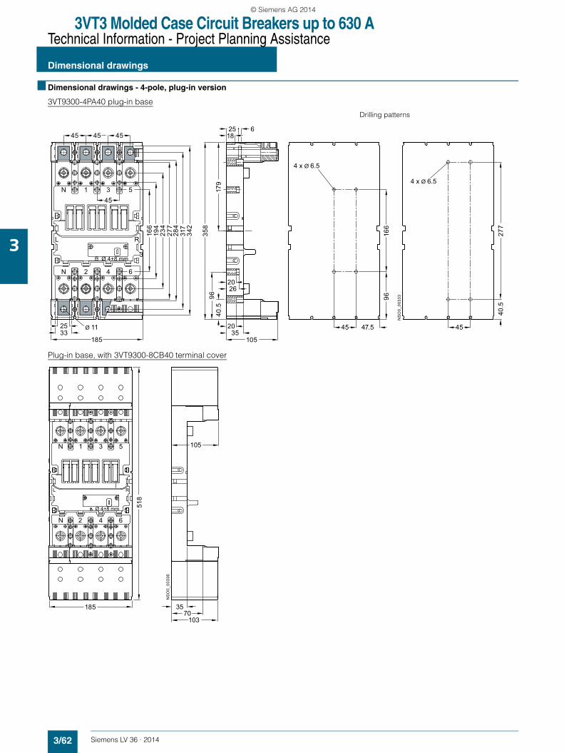
3VT3 Molded Case Circuit Breakers up to 630 ATechnical Information - Project Planning Assistance
Dimensional drawings
3/62 Siemens LV 36 · 2014
3
■ Dimensional drawings - 4-pole, plug-in version
3VT9300-4PA40 plug-in base
Drilling patterns
Plug-in base, with 3VT9300-8CB40 terminal cover
NS
O0_
0033
3
Ø 4+8 mm
L R
N
N
2
25
45
166
194
234
277
342
317
284
358
179
96 9616
6
277
45 45 45
33Ø 11
3520
2026
105185
4 6
1 3 5
45 45
1825 6
3
40.5
40.5
47.5
4 x Ø 6.5
4 x Ø 6.5
518
N 1 3 5
N 2 4 6
L R
Ø 4+8 mm
NS
O0_
0033
6
3570
103
105
185
LV36_2014.book Seite 62 Freitag, 31. Januar 2014 4:36 16
© Siemens AG 2014

3VT3 Molded Case Circuit Breakers up to 630 ATechnical Information - Project Planning Assistance
Dimensional drawings
3/63Siemens LV 36 · 2014
3
Plug-in version
Plug-in version, rear connection with 3VT9300-4RC30 + 3VT9300-4RC00 connecting set
Drilling pattern
185
358
TEST
ON
OFF
105140
157187
NS
O0_
0033
7
185
358
TEST
ON
OFF
317
25
Ø 11
20
5396
105
4 x Ø 6.5
45
9616
667
263
170
45 358
35
NS
O0_
0033
8
20.5 40.5
47.5
LV36_2014.book Seite 63 Freitag, 31. Januar 2014 4:36 16
© Siemens AG 2014
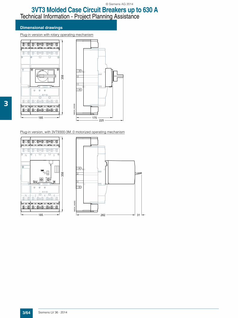
3VT3 Molded Case Circuit Breakers up to 630 ATechnical Information - Project Planning Assistance
Dimensional drawings
3/64 Siemens LV 36 · 2014
3
Plug-in version with rotary operating mechanism
Plug-in version, with 3VT9300-3M..0 motorized operating mechanism
175225
185
358
TEST
NS
O0_
0033
9
N 1 3 5
185
N 2 4 6
358
TEST
NS
O0_
0029
3
282 31
Ø 4,3 max.
AUTO
MANUAL
LV36_2014.book Seite 64 Freitag, 31. Januar 2014 4:36 16
© Siemens AG 2014
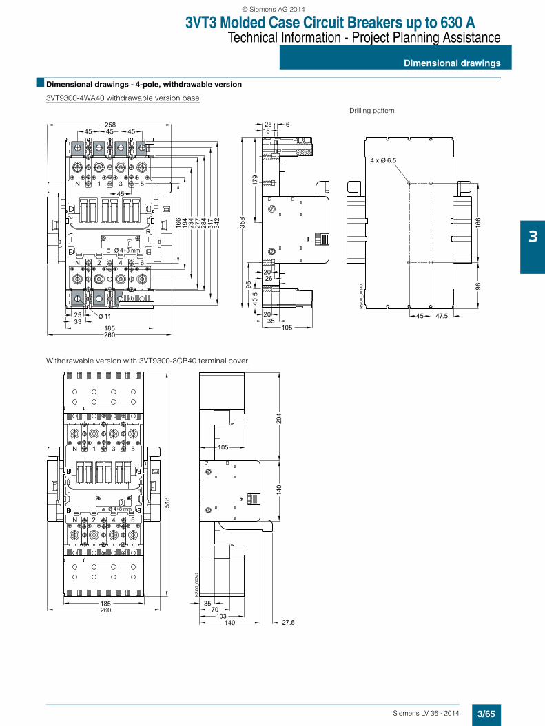
3VT3 Molded Case Circuit Breakers up to 630 ATechnical Information - Project Planning Assistance
Dimensional drawings
3/65Siemens LV 36 · 2014
3
■ Dimensional drawings - 4-pole, withdrawable version
3VT9300-4WA40 withdrawable version base
Drilling pattern
Withdrawable version with 3VT9300-8CB40 terminal coverN
SO
0_00
340
166
194
234
277
342
317
284
Ø 4+8 mm
L R
N
N
2
25
45
45 45 45
33Ø 11
185
4 6
1 3 5
258
260
358
179
96
3520
2026
105
1825 6
9616
6
45
40.5
47.5
4 x Ø 6.5
NS
O0_
0034
2
140
204
185260
518
N 1 3 5
N 2 4 6
L R
3570
103140
105
Ø 4+8 mm
27.5
LV36_2014.book Seite 65 Freitag, 31. Januar 2014 4:36 16
© Siemens AG 2014
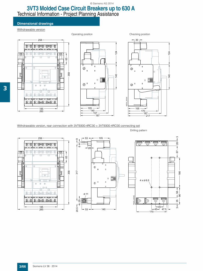
3VT3 Molded Case Circuit Breakers up to 630 ATechnical Information - Project Planning Assistance
Dimensional drawings
3/66 Siemens LV 36 · 2014
3
Withdrawable version
Operating position Checking position
Withdrawable version, rear connection with 3VT9300-4RC30 + 3VT9300-4RC00 connecting set
Drilling pattern
185
258
6535
8
TEST
260
ON
OFF
105140
15714
012
4
140
124
30
NS
O0_
0034
4
187
105170
187217
185
258
6535
8
317
TEST
260
ON
OFF
140
105
25
53
Ø 11
20
5396
45
9616
667
263
170
45 358
35
NS
O0_
0034
5
20.5
4 x Ø 6.5
47.5
LV36_2014.book Seite 66 Freitag, 31. Januar 2014 4:36 16
© Siemens AG 2014
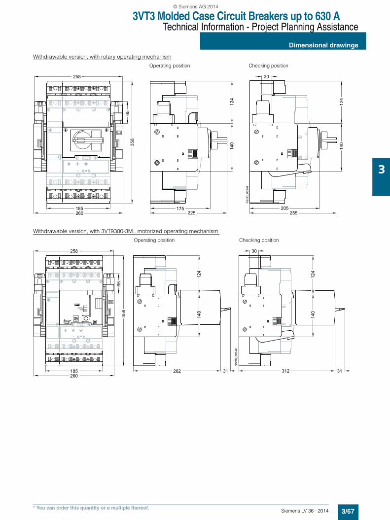
3VT3 Molded Case Circuit Breakers up to 630 ATechnical Information - Project Planning Assistance
Dimensional drawings
3/67Siemens LV 36 · 2014* You can order this quantity or a multiple thereof.
3
Withdrawable version, with rotary operating mechanism
Operating position Checking position
Withdrawable version, with 3VT9300-3M.. motorized operating mechanism
Operating position Checking position
175225
140
205185
258
6535
8
TEST
260 255
124
140
124
30
NS
O0_
0034
7
282 31
140
312185
258
6535
8
260
124
30
31
140
124
NS
O0_
0034
8
TEST
Ø 4,3 max.
AUTO
MANUAL
LV36_2014.book Seite 67 Freitag, 31. Januar 2014 4:36 16
© Siemens AG 2014
3VT3 Molded Case Circuit Breakers up to 630 ATechnical Information - Project Planning Assistance
Notes
3/68 Siemens LV 36 · 2014
3
LV36_03_02.fm Seite 68 Montag, 3. Februar 2014 2:52 14
© Siemens AG 2014