automation - wegecatalog.weg.net/files/wegnet/weg-dw-molded-case-circuit-breaker... · 4 molded...
TRANSCRIPT
Motors | Automation | Energy | Transmission & Distribution | Coatings
Automation Molded CaseCircuit Breakers IEC Style
www.weg.net
Molded Case Circuit breakers2
Summary
Molded Case Circuit Breakers 04
Installation and Connections 29
Accessories 18
Overview and Technical Data 06
Characteristic Curves 32
Dimensions (mm) 39
Reference Code 08
Selection Guide 09
Trip Units 16
Molded Case Circuit Breakers
www.weg.net
Molded Case Circuit Breakers4
Molded Case Circuit Breakers
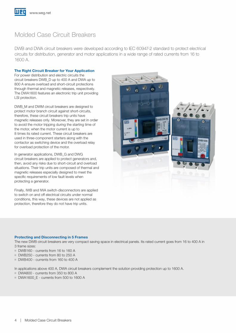
The Right Circuit Breaker for Your ApplicationFor power distribution and electric circuits the circuit breakers DWB_D up to 400 A and DWA up to 800 A ensure overload and short-circuit protections through thermal and magnetic releases, respectively.The DWA1600 features an electronic trip unit providing LSI protection.
DWB_M and DWM circuit breakers are designed to protect motor branch circuit against short-circuits, therefore, these circuit breakers trip units have magnetic releases only. Moreover, they are set in order to avoid the motor tripping during the starting time of the motor, when the motor current is up to 8 times its rated current. These circuit breakers are used in three-component starters along with the contactor as switching device and the overload relay for overload protection of the motor.
In generator applications, DWB_G and DWG circuit breakers are applied to protect generators and, then, avoid any risks due to short-circuit and overload situations. Their trip units are composed of thermal and magnetic releases especially designed to meet the specific requirements of low fault levels when protecting a generator.
Finally, IWB and IWA switch-disconnectors are applied to switch on and off electrical circuits under normal conditions, this way, these devices are not applied as protection, therefore they do not have trip units.
DWB and DWA circuit breakers were developed according to IEC 60947-2 standard to protect electrical circuits for distribution, generator and motor applications in a wide range of rated currents from 16 to 1600 A.
Protecting and Disconnecting in 5 FramesThe new DWB circuit breakers are very compact saving space in electrical panels. Its rated current goes from 16 to 400 A in 3 frame sizes:g DWB160 - currents from 16 to 160 Ag DWB250 - currents from 80 to 250 A
g DWB400 - currents from 160 to 400 A
In applications above 400 A, DWA circuit breakers complement the solution providing protection up to 1600 A.g DWA800 - currents from 350 to 800 Ag DWA1600_E - currents from 500 to 1600 A
www.weg.net
Molded Case Circuit Breakers 5
Molded Case Circuit Breakers
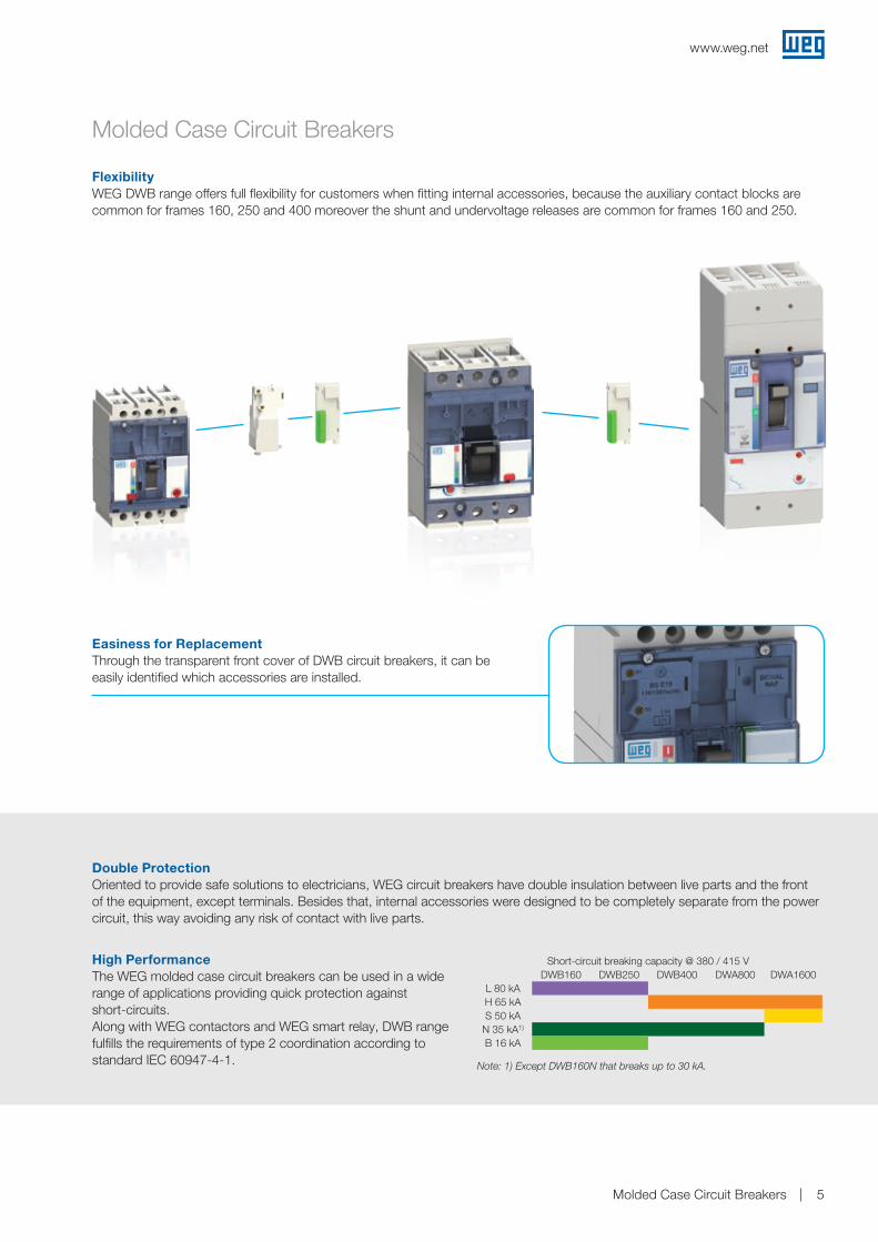
FlexibilityWEG DWB range offers full flexibility for customers when fitting internal accessories, because the auxiliary contact blocks are common for frames 160, 250 and 400 moreover the shunt and undervoltage releases are common for frames 160 and 250.
Easiness for ReplacementThrough the transparent front cover of DWB circuit breakers, it can be easily identified which accessories are installed.
Double ProtectionOriented to provide safe solutions to electricians, WEG circuit breakers have double insulation between live parts and the front of the equipment, except terminals. Besides that, internal accessories were designed to be completely separate from the power circuit, this way avoiding any risk of contact with live parts.
High PerformanceThe WEG molded case circuit breakers can be used in a wide range of applications providing quick protection against short-circuits.Along with WEG contactors and WEG smart relay, DWB range fulfills the requirements of type 2 coordination according to standard IEC 60947-4-1.
Short-circuit breaking capacity @ 380 / 415 VDWB160 DWB250 DWB400 DWA800 DWA1600
L 80 kAH 65 kAS 50 kA
N 35 kA1)
B 16 kA
Note: 1) Except DWB160N that breaks up to 30 kA.
www.weg.net
Molded Case Circuit Breakers6
Notes: 1) Not applicable for DWA1600.2) For other temperatures, see section Installation and connections.3) Circuit breakers with rated currents of 16, 20, 25 and 32 A, the short-circuit breaking capacity Icu is 20 kA.4) Circuit breakers with rated currents of 16, 20, 25 and 32 A, the short-circuit breaking capacity Icu is 15 kA.5) Valid for DWA800 up to 630 A.6) Not considering phase barriers and/or terminal covers.
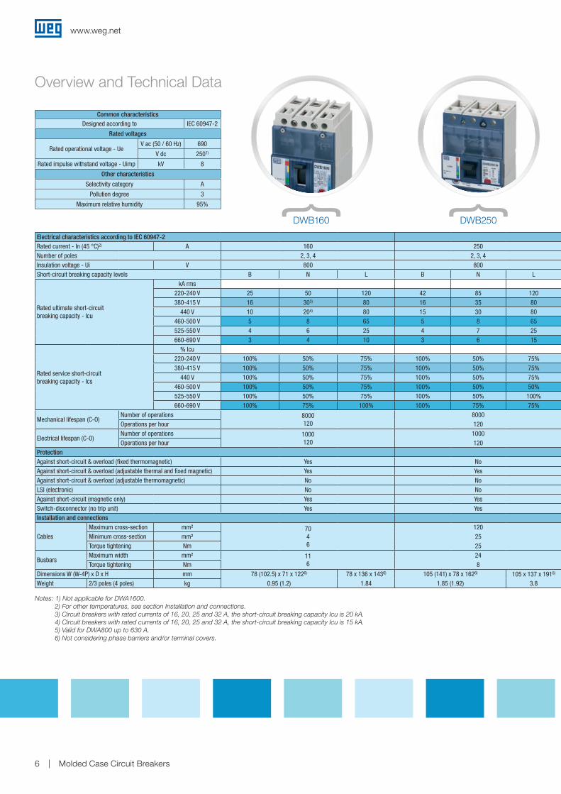
Electrical characteristics according to IEC 60947-2Rated current - In (45 °C)2) A 160Number of poles 2, 3, 4Insulation voltage - Ui V 800Short-circuit breaking capacity levels B N L
Rated ultimate short-circuit breaking capacity - Icu
kA rms220-240 V 25 50 120380-415 V 16 303) 80
440 V 10 204) 80460-500 V 5 8 65525-550 V 4 6 25660-690 V 3 4 10
Rated service short-circuit breaking capacity - Ics
% Icu220-240 V 100% 50% 75%380-415 V 100% 50% 75%
440 V 100% 50% 75%460-500 V 100% 50% 75%525-550 V 100% 50% 75%660-690 V 100% 75% 100%
Mechanical lifespan (C-O)Number of operations 8000
120 Operations per hour
Electrical lifespan (C-O)Number of operations 1000
120 Operations per hourProtectionAgainst short-circuit & overload (fixed thermomagnetic) YesAgainst short-circuit & overload (adjustable thermal and fixed magnetic) YesAgainst short-circuit & overload (adjustable thermomagnetic) NoLSI (electronic) NoAgainst short-circuit (magnetic only) YesSwitch-disconnector (no trip unit) YesInstallation and connections
CablesMaximum cross-section mm² 70
46
Minimum cross-section mm²Torque tightening Nm
BusbarsMaximum width mm² 11
6Torque tightening NmDimensions W (W-4P) x D x H mm 78 (102.5) x 71 x 1226) 78 x 136 x 1436)
Weight 2/3 poles (4 poles) kg 0.95 (1.2) 1.84
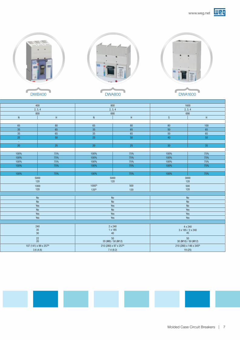
250 400 800 16002, 3, 4 2, 3, 4 2, 3, 4 2, 3, 4800 800 690 690
B N L N H N H S H
42 85 120 65 80 65 80 80 10016 35 80 35 65 35 65 50 6515 30 80 35 65 35 65 50 655 8 65 25 50 25 50 40 504 7 25 -3 6 15 20 25 20 25 30 35
100% 50% 75% 100% 75% 100% 75% 100% 75%100% 50% 75% 100% 75% 100% 75% 100% 75%100% 50% 75% 100% 75% 100% 75% 100% 75%100% 50% 50% 100% 75% 100% 75% 100% 75%100% 50% 100%100% 75% 75% 100% 75% 100% 75% 100% 75%
8000 5000 120
5000 120
3000 120 120
1000 1000 120
10005) 500 500 120 120 1205) 120
No No No NoYes No No NoNo Yes Yes NoNo No No YesYes Yes Yes YesYes Yes Yes Yes
120 2403530
2 x 2401 x 185
40
4 x 2403 x 185 / 2 x 240
45252524 22
2050
20 (M8) / 50 (M12)50
30 (M10) / 50 (M12)8105 (141) x 78 x 1626) 105 x 137 x 1916) 107 (141) x 99 x 2576) 210 (280) x 97 x 2576) 210 (280) x 146 x 3456)
1.85 (1.92) 3.8 3.6 (4.6) 7.4 (9.2) 19 (25)
Common characteristicsDesigned according to IEC 60947-2
Rated voltages
Rated operational voltage - UeV ac (50 / 60 Hz) 690
V dc 2501)
Rated impulse withstand voltage - Uimp kV 8
Other characteristics
Selectivity category A
Pollution degree 3
Maximum relative humidity 95%
DWB160 DWB250
Overview and Technical Data
www.weg.net
Molded Case Circuit Breakers 7
250 400 800 16002, 3, 4 2, 3, 4 2, 3, 4 2, 3, 4800 800 690 690
B N L N H N H S H
42 85 120 65 80 65 80 80 10016 35 80 35 65 35 65 50 6515 30 80 35 65 35 65 50 655 8 65 25 50 25 50 40 504 7 25 -3 6 15 20 25 20 25 30 35
100% 50% 75% 100% 75% 100% 75% 100% 75%100% 50% 75% 100% 75% 100% 75% 100% 75%100% 50% 75% 100% 75% 100% 75% 100% 75%100% 50% 50% 100% 75% 100% 75% 100% 75%100% 50% 100%100% 75% 75% 100% 75% 100% 75% 100% 75%
8000 5000 120
5000 120
3000 120 120
1000 1000 120
10005) 500 500 120 120 1205) 120
No No No NoYes No No NoNo Yes Yes NoNo No No YesYes Yes Yes YesYes Yes Yes Yes
120 2403530
2 x 2401 x 185
40
4 x 2403 x 185 / 2 x 240
45252524 22
2050
20 (M8) / 50 (M12)50
30 (M10) / 50 (M12)8105 (141) x 78 x 1626) 105 x 137 x 1916) 107 (141) x 99 x 2576) 210 (280) x 97 x 2576) 210 (280) x 146 x 3456)
1.85 (1.92) 3.8 3.6 (4.6) 7.4 (9.2) 19 (25)
DWB400 DWA800 DWA1600
www.weg.net
Molded Case Circuit Breakers8
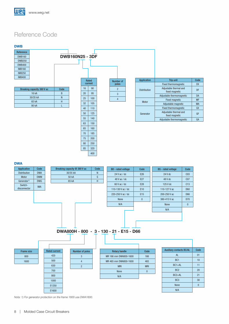
DWB
Reference Code
DWA Application Code
Distribution DWA
Motor DWM
Generator1) DWG
Switch-disconnector
IWA
Breaking capacity @ 380 V ac Code
30/35 kA N
50 kA S
65 kA H
DWA800H - 800 - 3 - 130 - 21 - E15 - D66
Number of poles
3
4
2
Auxiliary contacts BC/AL Code
AL 01
BC1 10
BC1+AL 11
BC2 20
BC2+AL 21
BC3 30
None 0
N/A
Rotary handle Code
MR 166 mm DWA800-1600 166
MR 465 mm DWA800-1600 465
MRI MRI
None 0
N/A
BD - rated voltage Code
24 V ac / dc E26
48 V ac / dc E27
60 V ac / dc E28
110-130 V ac / dc E10
220-250 V ac / dc E15
None 0
N/A
BS - rated voltage Code
24 V dc C03
48 V dc C07
125 V dc C13
110-127 V ac D60
200-250 V ac D66
380-415 V ac D70
None 0
N/A
Frame size
800
1600
Rated current
420
500
630
700
800
1000
E1250
E1600
Nota: 1) For generator protection on the frame 1600 use DWA1600.
DWB160N25 - 3DF Reference
DWB160
DWB250
DWB400
IWB160
IWB250
IWB400Rated
current
16 90
20 95
25 100
32 105
40 110
50 125
55 140
63 150
65 160
70 185
75 200
80 250
85 320
400
Breaking capacity 380 V ac Code
16 kA B
30/35 kA N
65 kA H
80 kA L
Number of poles
2
3
4
Application Trip unit Code
Distribution
Fixed thermomagnetic DX
Adjustable thermal and fixed magnetic
DF
Adjustable thermomagnetic DA
MotorFixed magnetic MF
Adjustable magnetic MA
Generator
Fixed thermomagnetic GX
Adjustable thermal and fixed magnetic
GF
Adjustable thermomagnetic GA
www.weg.net
Molded Case Circuit Breakers 9
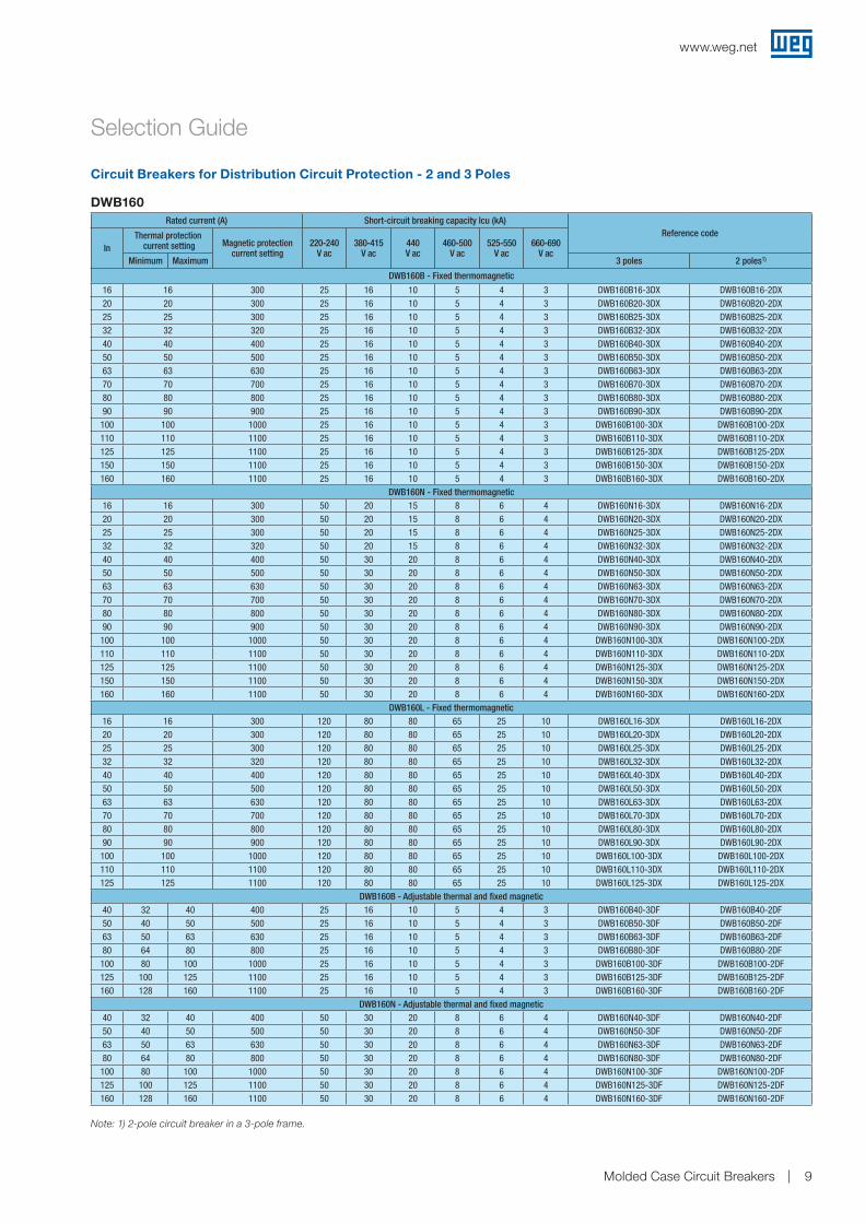
Selection Guide
Rated current (A) Short-circuit breaking capacity Icu (kA)Reference code
InThermal protection
current setting Magnetic protection current setting
220-240V ac
380-415V ac
440V ac
460-500V ac
525-550V ac
660-690V ac
Minimum Maximum 3 poles 2 poles1)
DWB160B - Fixed thermomagnetic
16 16 300 25 16 10 5 4 3 DWB160B16-3DX DWB160B16-2DX20 20 300 25 16 10 5 4 3 DWB160B20-3DX DWB160B20-2DX25 25 300 25 16 10 5 4 3 DWB160B25-3DX DWB160B25-2DX32 32 320 25 16 10 5 4 3 DWB160B32-3DX DWB160B32-2DX40 40 400 25 16 10 5 4 3 DWB160B40-3DX DWB160B40-2DX50 50 500 25 16 10 5 4 3 DWB160B50-3DX DWB160B50-2DX63 63 630 25 16 10 5 4 3 DWB160B63-3DX DWB160B63-2DX70 70 700 25 16 10 5 4 3 DWB160B70-3DX DWB160B70-2DX80 80 800 25 16 10 5 4 3 DWB160B80-3DX DWB160B80-2DX90 90 900 25 16 10 5 4 3 DWB160B90-3DX DWB160B90-2DX100 100 1000 25 16 10 5 4 3 DWB160B100-3DX DWB160B100-2DX110 110 1100 25 16 10 5 4 3 DWB160B110-3DX DWB160B110-2DX125 125 1100 25 16 10 5 4 3 DWB160B125-3DX DWB160B125-2DX150 150 1100 25 16 10 5 4 3 DWB160B150-3DX DWB160B150-2DX160 160 1100 25 16 10 5 4 3 DWB160B160-3DX DWB160B160-2DX
DWB160N - Fixed thermomagnetic16 16 300 50 20 15 8 6 4 DWB160N16-3DX DWB160N16-2DX20 20 300 50 20 15 8 6 4 DWB160N20-3DX DWB160N20-2DX25 25 300 50 20 15 8 6 4 DWB160N25-3DX DWB160N25-2DX32 32 320 50 20 15 8 6 4 DWB160N32-3DX DWB160N32-2DX40 40 400 50 30 20 8 6 4 DWB160N40-3DX DWB160N40-2DX50 50 500 50 30 20 8 6 4 DWB160N50-3DX DWB160N50-2DX63 63 630 50 30 20 8 6 4 DWB160N63-3DX DWB160N63-2DX70 70 700 50 30 20 8 6 4 DWB160N70-3DX DWB160N70-2DX80 80 800 50 30 20 8 6 4 DWB160N80-3DX DWB160N80-2DX90 90 900 50 30 20 8 6 4 DWB160N90-3DX DWB160N90-2DX
100 100 1000 50 30 20 8 6 4 DWB160N100-3DX DWB160N100-2DX110 110 1100 50 30 20 8 6 4 DWB160N110-3DX DWB160N110-2DX125 125 1100 50 30 20 8 6 4 DWB160N125-3DX DWB160N125-2DX150 150 1100 50 30 20 8 6 4 DWB160N150-3DX DWB160N150-2DX160 160 1100 50 30 20 8 6 4 DWB160N160-3DX DWB160N160-2DX
DWB160L - Fixed thermomagnetic16 16 300 120 80 80 65 25 10 DWB160L16-3DX DWB160L16-2DX20 20 300 120 80 80 65 25 10 DWB160L20-3DX DWB160L20-2DX25 25 300 120 80 80 65 25 10 DWB160L25-3DX DWB160L25-2DX32 32 320 120 80 80 65 25 10 DWB160L32-3DX DWB160L32-2DX40 40 400 120 80 80 65 25 10 DWB160L40-3DX DWB160L40-2DX50 50 500 120 80 80 65 25 10 DWB160L50-3DX DWB160L50-2DX63 63 630 120 80 80 65 25 10 DWB160L63-3DX DWB160L63-2DX70 70 700 120 80 80 65 25 10 DWB160L70-3DX DWB160L70-2DX80 80 800 120 80 80 65 25 10 DWB160L80-3DX DWB160L80-2DX90 90 900 120 80 80 65 25 10 DWB160L90-3DX DWB160L90-2DX
100 100 1000 120 80 80 65 25 10 DWB160L100-3DX DWB160L100-2DX110 110 1100 120 80 80 65 25 10 DWB160L110-3DX DWB160L110-2DX125 125 1100 120 80 80 65 25 10 DWB160L125-3DX DWB160L125-2DX
DWB160B - Adjustable thermal and fixed magnetic40 32 40 400 25 16 10 5 4 3 DWB160B40-3DF DWB160B40-2DF50 40 50 500 25 16 10 5 4 3 DWB160B50-3DF DWB160B50-2DF63 50 63 630 25 16 10 5 4 3 DWB160B63-3DF DWB160B63-2DF80 64 80 800 25 16 10 5 4 3 DWB160B80-3DF DWB160B80-2DF100 80 100 1000 25 16 10 5 4 3 DWB160B100-3DF DWB160B100-2DF125 100 125 1100 25 16 10 5 4 3 DWB160B125-3DF DWB160B125-2DF160 128 160 1100 25 16 10 5 4 3 DWB160B160-3DF DWB160B160-2DF
DWB160N - Adjustable thermal and fixed magnetic40 32 40 400 50 30 20 8 6 4 DWB160N40-3DF DWB160N40-2DF50 40 50 500 50 30 20 8 6 4 DWB160N50-3DF DWB160N50-2DF63 50 63 630 50 30 20 8 6 4 DWB160N63-3DF DWB160N63-2DF80 64 80 800 50 30 20 8 6 4 DWB160N80-3DF DWB160N80-2DF100 80 100 1000 50 30 20 8 6 4 DWB160N100-3DF DWB160N100-2DF125 100 125 1100 50 30 20 8 6 4 DWB160N125-3DF DWB160N125-2DF160 128 160 1100 50 30 20 8 6 4 DWB160N160-3DF DWB160N160-2DF
Note: 1) 2-pole circuit breaker in a 3-pole frame.
Circuit Breakers for Distribution Circuit Protection - 2 and 3 Poles
DWB160
www.weg.net
Molded Case Circuit Breakers10
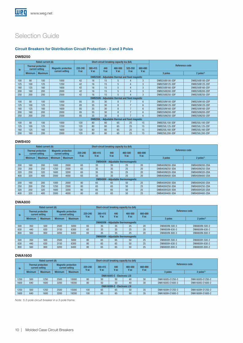
Note: 1) 2-pole circuit breaker in a 3-pole frame.
Selection Guide
Rated current (A) Short-circuit breaking capacity Icu (kA)Reference code
InThermal protection
current settingMagnetic protection
current setting 220-240V ac
380-415 V ac
440V ac
460-500 V ac
660-690V ac
Minimum Maximum Minimum Maximum 3 poles 2 poles1)
DWA800N - Adjustable thermomagnetic500 350 500 2500 5000 65 35 35 25 20 DWA800N-500-3 DWA800N-500-2630 440 630 3150 6300 65 35 35 25 20 DWA800N-630-3 DWA800N-630-2800 560 800 3200 6400 65 35 35 25 20 DWA800N-800-3 DWA800N-800-2
DWA800H - Adjustable thermomagnetic500 350 500 2500 5000 80 65 65 50 25 DWA800H-500-3 DWA800H-500-2630 440 630 3150 6300 80 65 65 50 25 DWA800H-630-3 DWA800H-630-2800 560 800 3200 6400 80 65 65 50 25 DWA800H-800-3 DWA800H-800-2
Rated current (A) Short-circuit breaking capacity Icu (kA)Reference code
InThermal protection
current settingMagnetic protection
current setting 220-240V ac
380-415 V ac
440V ac
460-500 V ac
660-690V ac
Minimum Maximum Minimum Maximum 3 poles 2 poles1)
DWA1600S-E - Electronic LSI1250 500 1250 2500 15000 80 50 50 40 30 DWA1600S-E1250-3 DWA1600S-E1250-21600 640 1600 3200 19200 80 50 50 40 30 DWA1600S-E1600-3 DWA1600S-E1600-2
DWA1600H-E - Electronic LSI1250 500 1250 2500 15000 100 65 65 50 35 DWA1600H-E1250-3 DWA1600H-E1250-21600 640 1600 3200 19200 100 65 65 50 35 DWA1600H-E1600-3 DWA1600H-E1600-2
DWA800
DWA1600
Rated current (A) Short-circuit breaking capacity Icu (kA)Reference code
InThermal protection
current settingMagnetic protection
current setting 220-240V ac
380-415 V ac
440V ac
460-500 V ac
660-690V ac
Minimum Maximum Minimum Maximum 3 poles 2 poles1)
DWB400N - Adjustable thermomagnetic200 160 200 1000 2000 65 35 35 25 20 DWB400N200-3DA DWB400N200-2DA250 200 250 1250 2500 65 35 35 25 20 DWB400N250-3DA DWB400N250-2DA320 250 320 1600 3200 65 35 35 25 20 DWB400N320-3DA DWB400N320-2DA400 320 400 2000 4000 65 35 35 25 20 DWB400N400-3DA DWB400N400-2DA
DWB400H - Adjustable thermomagnetic200 160 200 1000 2000 80 65 65 50 25 DWB400H200-3DA DWB400H200-2DA250 200 250 1250 2500 80 65 65 50 25 DWB400H250-3DA DWB400H250-2DA320 250 320 1600 3200 80 65 65 50 25 DWB400H320-3DA DWB400H320-2DA400 320 400 2000 4000 80 65 65 50 25 DWB400H400-3DA DWB400H400-2DA
Rated current (A) Short-circuit breaking capacity Icu (kA)Reference code
InThermal protection
current setting Magnetic protection current setting
220-240V ac
380-415 V ac
440V ac
460-500 V ac
525-550V ac
660-690V ac
Minimum Maximum 3 poles 2 poles1)
DWB250B - Adjustable thermal and fixed magnetic100 80 100 1000 42 16 15 5 4 3 DWB250B100-3DF DWB250B100-2DF125 100 125 1250 42 16 15 5 4 3 DWB250B125-3DF DWB250B125-2DF160 125 160 1600 42 16 15 5 4 3 DWB250B160-3DF DWB250B160-2DF200 160 200 2000 42 16 15 5 4 3 DWB250B200-3DF DWB250B200-2DF250 200 250 2500 42 16 15 5 4 3 DWB250B250-3DF DWB250B250-2DF
DWB250N - Adjustable thermal and fixed magnetic100 80 100 1000 85 35 30 8 7 6 DWB250N100-3DF DWB250N100-2DF125 100 125 1250 85 35 30 8 7 6 DWB250N125-3DF DWB250N125-2DF160 125 160 1600 85 35 30 8 7 6 DWB250N160-3DF DWB250N160-2DF200 160 200 2000 85 35 30 8 7 6 DWB250N200-3DF DWB250N200-2DF250 200 250 2500 85 35 30 8 7 6 DWB250N250-3DF DWB250N250-2DF
DWB250L - Adjustable thermal and fixed magnetic100 80 100 1000 120 80 80 65 25 15 DWB250L100-3DF DWB250L100-2DF125 100 125 1250 120 80 80 65 25 15 DWB250L125-3DF DWB250L125-2DF160 125 160 1600 120 80 80 65 25 15 DWB250L160-3DF DWB250L160-2DF200 160 200 2000 120 80 80 65 25 15 DWB250L200-3DF DWB250L200-2DF
Circuit Breakers for Distribution Circuit Protection - 2 and 3 Poles
DWB250
DWB400
www.weg.net
Molded Case Circuit Breakers 11
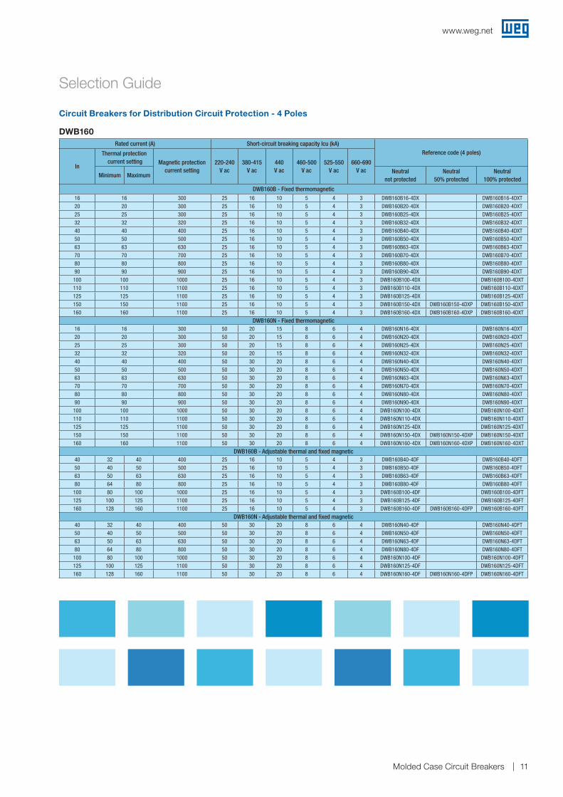
Selection Guide
Circuit Breakers for Distribution Circuit Protection - 4 Poles
Rated current (A) Short-circuit breaking capacity Icu (kA)Reference code (4 poles)
In
Thermal protection current setting Magnetic protection
current setting220-240
V ac380-415
V ac440V ac
460-500V ac
525-550V ac
660-690V ac
Minimum MaximumNeutral
not protectedNeutral
50% protectedNeutral
100% protected
DWB160B - Fixed thermomagnetic16 16 300 25 16 10 5 4 3 DWB160B16-4DX DWB160B16-4DXT20 20 300 25 16 10 5 4 3 DWB160B20-4DX DWB160B20-4DXT25 25 300 25 16 10 5 4 3 DWB160B25-4DX DWB160B25-4DXT32 32 320 25 16 10 5 4 3 DWB160B32-4DX DWB160B32-4DXT40 40 400 25 16 10 5 4 3 DWB160B40-4DX DWB160B40-4DXT50 50 500 25 16 10 5 4 3 DWB160B50-4DX DWB160B50-4DXT63 63 630 25 16 10 5 4 3 DWB160B63-4DX DWB160B63-4DXT70 70 700 25 16 10 5 4 3 DWB160B70-4DX DWB160B70-4DXT80 80 800 25 16 10 5 4 3 DWB160B80-4DX DWB160B80-4DXT90 90 900 25 16 10 5 4 3 DWB160B90-4DX DWB160B90-4DXT
100 100 1000 25 16 10 5 4 3 DWB160B100-4DX DWB160B100-4DXT110 110 1100 25 16 10 5 4 3 DWB160B110-4DX DWB160B110-4DXT125 125 1100 25 16 10 5 4 3 DWB160B125-4DX DWB160B125-4DXT150 150 1100 25 16 10 5 4 3 DWB160B150-4DX DWB160B150-4DXP DWB160B150-4DXT160 160 1100 25 16 10 5 4 3 DWB160B160-4DX DWB160B160-4DXP DWB160B160-4DXT
DWB160N - Fixed thermomagnetic16 16 300 50 20 15 8 6 4 DWB160N16-4DX DWB160N16-4DXT20 20 300 50 20 15 8 6 4 DWB160N20-4DX DWB160N20-4DXT25 25 300 50 20 15 8 6 4 DWB160N25-4DX DWB160N25-4DXT32 32 320 50 20 15 8 6 4 DWB160N32-4DX DWB160N32-4DXT40 40 400 50 30 20 8 6 4 DWB160N40-4DX DWB160N40-4DXT50 50 500 50 30 20 8 6 4 DWB160N50-4DX DWB160N50-4DXT63 63 630 50 30 20 8 6 4 DWB160N63-4DX DWB160N63-4DXT70 70 700 50 30 20 8 6 4 DWB160N70-4DX DWB160N70-4DXT80 80 800 50 30 20 8 6 4 DWB160N80-4DX DWB160N80-4DXT90 90 900 50 30 20 8 6 4 DWB160N90-4DX DWB160N90-4DXT
100 100 1000 50 30 20 8 6 4 DWB160N100-4DX DWB160N100-4DXT110 110 1100 50 30 20 8 6 4 DWB160N110-4DX DWB160N110-4DXT125 125 1100 50 30 20 8 6 4 DWB160N125-4DX DWB160N125-4DXT150 150 1100 50 30 20 8 6 4 DWB160N150-4DX DWB160N150-4DXP DWB160N150-4DXT160 160 1100 50 30 20 8 6 4 DWB160N160-4DX DWB160N160-4DXP DWB160N160-4DXT
DWB160B - Adjustable thermal and fixed magnetic40 32 40 400 25 16 10 5 4 3 DWB160B40-4DF DWB160B40-4DFT50 40 50 500 25 16 10 5 4 3 DWB160B50-4DF DWB160B50-4DFT63 50 63 630 25 16 10 5 4 3 DWB160B63-4DF DWB160B63-4DFT80 64 80 800 25 16 10 5 4 3 DWB160B80-4DF DWB160B80-4DFT
100 80 100 1000 25 16 10 5 4 3 DWB160B100-4DF DWB160B100-4DFT125 100 125 1100 25 16 10 5 4 3 DWB160B125-4DF DWB160B125-4DFT160 128 160 1100 25 16 10 5 4 3 DWB160B160-4DF DWB160B160-4DFP DWB160B160-4DFT
DWB160N - Adjustable thermal and fixed magnetic40 32 40 400 50 30 20 8 6 4 DWB160N40-4DF DWB160N40-4DFT50 40 50 500 50 30 20 8 6 4 DWB160N50-4DF DWB160N50-4DFT63 50 63 630 50 30 20 8 6 4 DWB160N63-4DF DWB160N63-4DFT80 64 80 800 50 30 20 8 6 4 DWB160N80-4DF DWB160N80-4DFT
100 80 100 1000 50 30 20 8 6 4 DWB160N100-4DF DWB160N100-4DFT125 100 125 1100 50 30 20 8 6 4 DWB160N125-4DF DWB160N125-4DFT160 128 160 1100 50 30 20 8 6 4 DWB160N160-4DF DWB160N160-4DFP DWB160N160-4DFT
DWB160
www.weg.net
Molded Case Circuit Breakers12
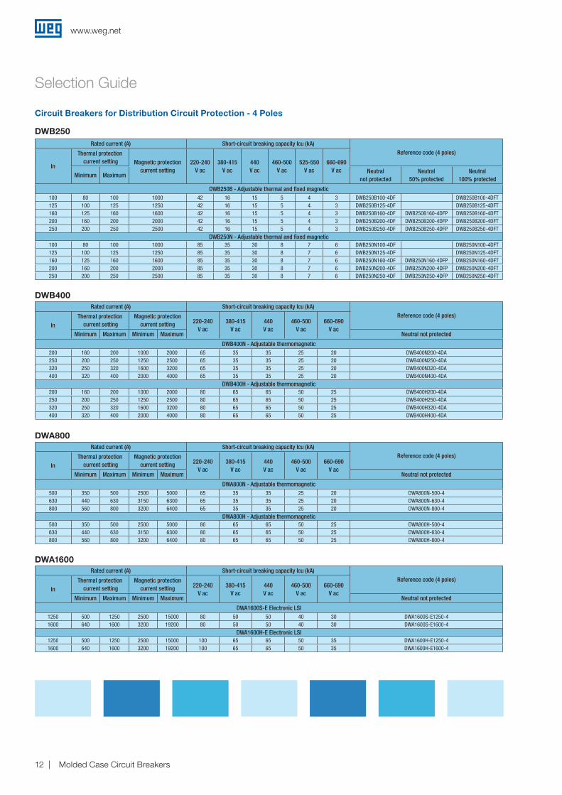
Rated current (A) Short-circuit breaking capacity Icu (kA)Reference code (4 poles)
In
Thermal protection current setting Magnetic protection
current setting220-240
V ac380-415
V ac440V ac
460-500V ac
525-550V ac
660-690V ac
Minimum MaximumNeutral
not protectedNeutral
50% protectedNeutral
100% protected
DWB250B - Adjustable thermal and fixed magnetic100 80 100 1000 42 16 15 5 4 3 DWB250B100-4DF DWB250B100-4DFT125 100 125 1250 42 16 15 5 4 3 DWB250B125-4DF DWB250B125-4DFT160 125 160 1600 42 16 15 5 4 3 DWB250B160-4DF DWB250B160-4DFP DWB250B160-4DFT200 160 200 2000 42 16 15 5 4 3 DWB250B200-4DF DWB250B200-4DFP DWB250B200-4DFT250 200 250 2500 42 16 15 5 4 3 DWB250B250-4DF DWB250B250-4DFP DWB250B250-4DFT
DWB250N - Adjustable thermal and fixed magnetic100 80 100 1000 85 35 30 8 7 6 DWB250N100-4DF DWB250N100-4DFT125 100 125 1250 85 35 30 8 7 6 DWB250N125-4DF DWB250N125-4DFT160 125 160 1600 85 35 30 8 7 6 DWB250N160-4DF DWB250N160-4DFP DWB250N160-4DFT200 160 200 2000 85 35 30 8 7 6 DWB250N200-4DF DWB250N200-4DFP DWB250N200-4DFT250 200 250 2500 85 35 30 8 7 6 DWB250N250-4DF DWB250N250-4DFP DWB250N250-4DFT
Rated current (A) Short-circuit breaking capacity Icu (kA)Reference code (4 poles)
InThermal protection
current settingMagnetic protection
current setting 220-240V ac
380-415V ac
440V ac
460-500V ac
660-690V ac
Minimum Maximum Minimum Maximum Neutral not protected
DWB400N - Adjustable thermomagnetic200 160 200 1000 2000 65 35 35 25 20 DWB400N200-4DA250 200 250 1250 2500 65 35 35 25 20 DWB400N250-4DA320 250 320 1600 3200 65 35 35 25 20 DWB400N320-4DA400 320 400 2000 4000 65 35 35 25 20 DWB400N400-4DA
DWB400H - Adjustable thermomagnetic200 160 200 1000 2000 80 65 65 50 25 DWB400H200-4DA250 200 250 1250 2500 80 65 65 50 25 DWB400H250-4DA320 250 320 1600 3200 80 65 65 50 25 DWB400H320-4DA400 320 400 2000 4000 80 65 65 50 25 DWB400H400-4DA
Rated current (A) Short-circuit breaking capacity Icu (kA)Reference code (4 poles)
InThermal protection
current settingMagnetic protection
current setting 220-240V ac
380-415V ac
440V ac
460-500V ac
660-690V ac
Minimum Maximum Minimum Maximum Neutral not protected
DWA800N - Adjustable thermomagnetic500 350 500 2500 5000 65 35 35 25 20 DWA800N-500-4630 440 630 3150 6300 65 35 35 25 20 DWA800N-630-4800 560 800 3200 6400 65 35 35 25 20 DWA800N-800-4
DWA800H - Adjustable thermomagnetic500 350 500 2500 5000 80 65 65 50 25 DWA800H-500-4630 440 630 3150 6300 80 65 65 50 25 DWA800H-630-4800 560 800 3200 6400 80 65 65 50 25 DWA800H-800-4
Rated current (A) Short-circuit breaking capacity Icu (kA)Reference code (4 poles)
InThermal protection
current settingMagnetic protection
current setting 220-240V ac
380-415V ac
440V ac
460-500V ac
660-690V ac
Minimum Maximum Minimum Maximum Neutral not protected
DWA1600S-E Electronic LSI1250 500 1250 2500 15000 80 50 50 40 30 DWA1600S-E1250-41600 640 1600 3200 19200 80 50 50 40 30 DWA1600S-E1600-4
DWA1600H-E Electronic LSI1250 500 1250 2500 15000 100 65 65 50 35 DWA1600H-E1250-41600 640 1600 3200 19200 100 65 65 50 35 DWA1600H-E1600-4
Selection Guide
Circuit Breakers for Distribution Circuit Protection - 4 Poles
DWB250
DWB400
DWA800
DWA1600
www.weg.net
Molded Case Circuit Breakers 13
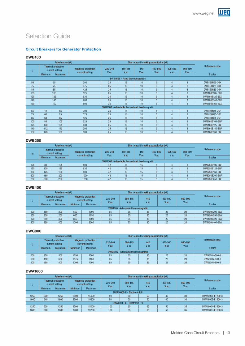
Selection Guide
Circuit Breakers for Generator Protection
Rated current (A) Short-circuit breaking capacity Icu (kA)Reference code
In
Thermal protection current setting Magnetic protection
current setting220-240
V ac380-415
V ac440V ac
460-500 V ac
525-550V ac
660-690V ac
Minimum Maximum 3 poles
DWB160B - Fixed thermomagnetic55 55 300 25 16 10 5 4 3 DWB160B55-3GX75 75 375 25 16 10 5 4 3 DWB160B75-3GX85 85 425 25 16 10 5 4 3 DWB160B85-3GX
105 105 525 25 16 10 5 4 3 DWB160B105-3GX125 125 630 25 16 10 5 4 3 DWB160B125-3GX140 140 700 25 16 10 5 4 3 DWB160B140-3GX160 160 800 25 16 10 5 4 3 DWB160B160-3GX
DWB160B - Adjustable thermal and fixed magnetic55 44 55 300 25 16 10 5 4 3 DWB160B55-3GF75 60 75 375 25 16 10 5 4 3 DWB160B75-3GF85 68 85 425 25 16 10 5 4 3 DWB160B85-3GF105 84 105 525 25 16 10 5 4 3 DWB160B105-3GF125 100 125 630 25 16 10 5 4 3 DWB160B125-3GF140 112 140 700 25 16 10 5 4 3 DWB160B140-3GF160 128 160 800 25 16 10 5 4 3 DWB160B160-3GF
Rated current (A) Short-circuit breaking capacity Icu (kA)Reference code
InThermal protection
current setting Magnetic protection current setting
220-240V ac
380-415V ac
440V ac
460-500 V ac
525-550V ac
660-690V ac
Minimum Maximum 3 polesDWB250B - Adjustable thermal and fixed magnetic
105 80 105 500 42 16 15 5 4 3 DWB250B105-3GF125 100 125 630 42 16 15 5 4 3 DWB250B125-3GF160 125 160 800 42 16 15 5 4 3 DWB250B160-3GF200 160 200 1000 42 16 15 5 4 3 DWB250B200-3GF250 200 250 1250 42 16 15 5 4 3 DWB250B250-3GF
Rated current (A) Short-circuit breaking capacity Icu (kA)Reference code
In
Thermal protection current setting
Magnetic protection current setting 220-240
V ac380-415
V ac440V ac
460-500 V ac
660-690V ac
Minimum Maximum Minimum Maximum 3 polesDWB400N - Adjustable thermomagnetic
200 160 200 500 1000 65 35 35 25 20 DWB400N200-3GA250 200 250 625 1250 65 35 35 25 20 DWB400N250-3GA320 250 320 800 1600 65 35 35 25 20 DWB400N320-3GA400 320 400 1000 2000 65 35 35 25 20 DWB400N400-3GA
Rated current (A) Short-circuit breaking capacity Icu (kA)Reference code
In
Thermal protection current setting
Magnetic protection current setting 220-240
V ac380-415
V ac440V ac
460-500 V ac
660-690V ac
Minimum Maximum Minimum Maximum 3 polesDWG800N - Adjustable thermomagnetic
500 350 500 1250 2500 65 35 35 25 20 DWG800N-500-3630 440 630 1575 3150 65 35 35 25 20 DWG800N-630-3800 560 800 2000 4000 65 35 35 25 20 DWG800N-800-3
Rated current (A) Short-circuit breaking capacity Icu (kA)Reference code
In
Thermal protection current setting
Magnetic protection current setting 220-240
V ac380-415
V ac440V ac
460-500 V ac
660-690V ac
Minimum Maximum Minimum Maximum 3 polesDWA1600S-E - Electronic LSI
1250 500 1250 2500 15000 80 50 50 40 30 DWA1600S-E1250-31600 640 1600 3200 19200 80 50 50 40 30 DWA1600S-E1600-3
DWA1600H-E - Electronic LSI1250 500 1250 2500 15000 100 65 65 50 35 DWA1600H-E1250-31600 640 1600 3200 19200 100 65 65 50 35 DWA1600H-E1600-3
DWB160
DWB250
DWB400
DWG800
DWA1600
www.weg.net
Molded Case Circuit Breakers14
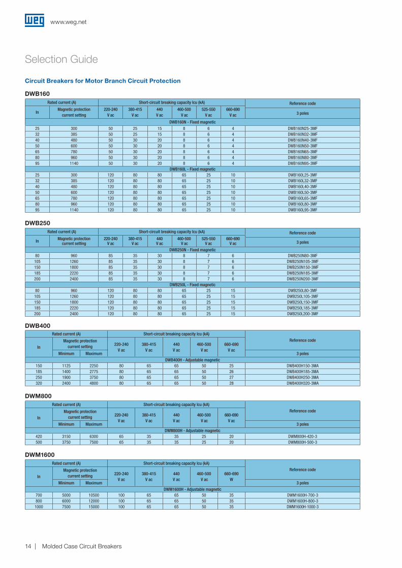
Selection Guide
Circuit Breakers for Motor Branch Circuit Protection
Rated current (A) Short-circuit breaking capacity Icu (kA) Reference code
InMagnetic protection
current setting220-240
V ac380-415
V ac440V ac
460-500 V ac
525-550V ac
660-690V ac 3 poles
DWB160N - Fixed magnetic25 300 50 25 15 8 6 4 DWB160N25-3MF32 385 50 25 15 8 6 4 DWB160N32-3MF40 480 50 30 20 8 6 4 DWB160N40-3MF50 600 50 30 20 8 6 4 DWB160N50-3MF65 780 50 30 20 8 6 4 DWB160N65-3MF80 960 50 30 20 8 6 4 DWB160N80-3MF95 1140 50 30 20 8 6 4 DWB160N95-3MF
DWB160L - Fixed magnetic25 300 120 80 80 65 25 10 DWB160L25-3MF32 385 120 80 80 65 25 10 DWB160L32-3MF40 480 120 80 80 65 25 10 DWB160L40-3MF50 600 120 80 80 65 25 10 DWB160L50-3MF65 780 120 80 80 65 25 10 DWB160L65-3MF80 960 120 80 80 65 25 10 DWB160L80-3MF95 1140 120 80 80 65 25 10 DWB160L95-3MF
Rated current (A) Short-circuit breaking capacity Icu (kA) Reference code
In Magnetic protection current setting
220-240V ac
380-415V ac
440V ac
460-500 V ac
525-550V ac
660-690V ac 3 poles
DWB250N - Fixed magnetic80 960 85 35 30 8 7 6 DWB250N80-3MF105 1260 85 35 30 8 7 6 DWB250N105-3MF150 1800 85 35 30 8 7 6 DWB250N150-3MF185 2220 85 35 30 8 7 6 DWB250N185-3MF200 2400 85 35 30 8 7 6 DWB250N200-3MF
DWB250L - Fixed magnetic80 960 120 80 80 65 25 15 DWB250L80-3MF105 1260 120 80 80 65 25 15 DWB250L105-3MF150 1800 120 80 80 65 25 15 DWB250L150-3MF185 2220 120 80 80 65 25 15 DWB250L185-3MF200 2400 120 80 80 65 25 15 DWB250L200-3MF
Rated current (A) Short-circuit breaking capacity Icu (kA)Reference code
InMagnetic protection
current setting 220-240V ac
380-415V ac
440V ac
460-500 V ac
660-690V ac
Minimum Maximum 3 polesDWB400H - Adjustable magnetic
150 1125 2250 80 65 65 50 25 DWB400H150-3MA185 1400 2775 80 65 65 50 26 DWB400H185-3MA250 1900 3750 80 65 65 50 27 DWB400H250-3MA320 2400 4800 80 65 65 50 28 DWB400H320-3MA
Rated current (A) Short-circuit breaking capacity Icu (kA)Reference code
InMagnetic protection
current setting 220-240V ac
380-415V ac
440V ac
460-500 V ac
660-690V ac
Minimum Maximum 3 polesDWM800H - Adjustable magnetic
420 3150 6300 65 35 35 25 20 DWM800H-420-3500 3750 7500 65 35 35 25 20 DWM800H-500-3
Rated current (A) Short-circuit breaking capacity Icu (kA)Reference code
InMagnetic protection
current setting 220-240V ac
380-415V ac
440V ac
460-500 V ac
660-690W
Minimum Maximum 3 polesDWM1600H - Adjustable magnetic
700 5000 10500 100 65 65 50 35 DWM1600H-700-3800 6000 12000 100 65 65 50 35 DWM1600H-800-31000 7500 15000 100 65 65 50 35 DWM1600H-1000-3
DWB160
DWB250
DWB400
DWM800
DWM1600
www.weg.net
Molded Case Circuit Breakers 15
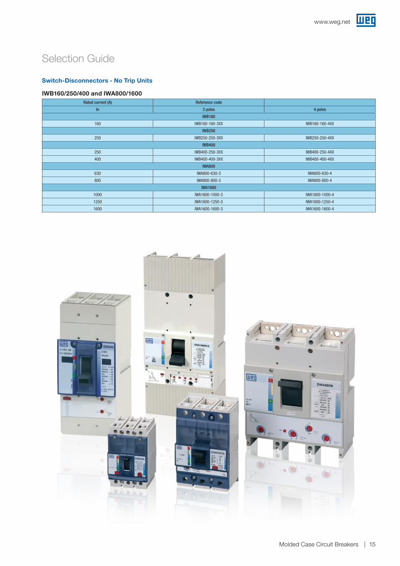
Rated current (A) Reference code
In 3 poles 4 poles
IWB160
160 IWB160-160-3XX IWB160-160-4XX
IWB250
250 IWB250-250-3XX IWB250-250-4XX
IWB400
250 IWB400-250-3XX IWB400-250-4XX
400 IWB400-400-3XX IWB400-400-4XX
IWA800
630 IWA800-630-3 IWA800-630-4
800 IWA800-800-3 IWA800-800-4
IWA1600
1000 IWA1600-1000-3 IWA1600-1000-4
1250 IWA1600-1250-3 IWA1600-1250-4
1600 IWA1600-1600-3 IWA1600-1600-4
Selection Guide
Switch-Disconnectors - No Trip Units
IWB160/250/400 and IWA800/1600
www.weg.net
Molded Case Circuit Breakers16
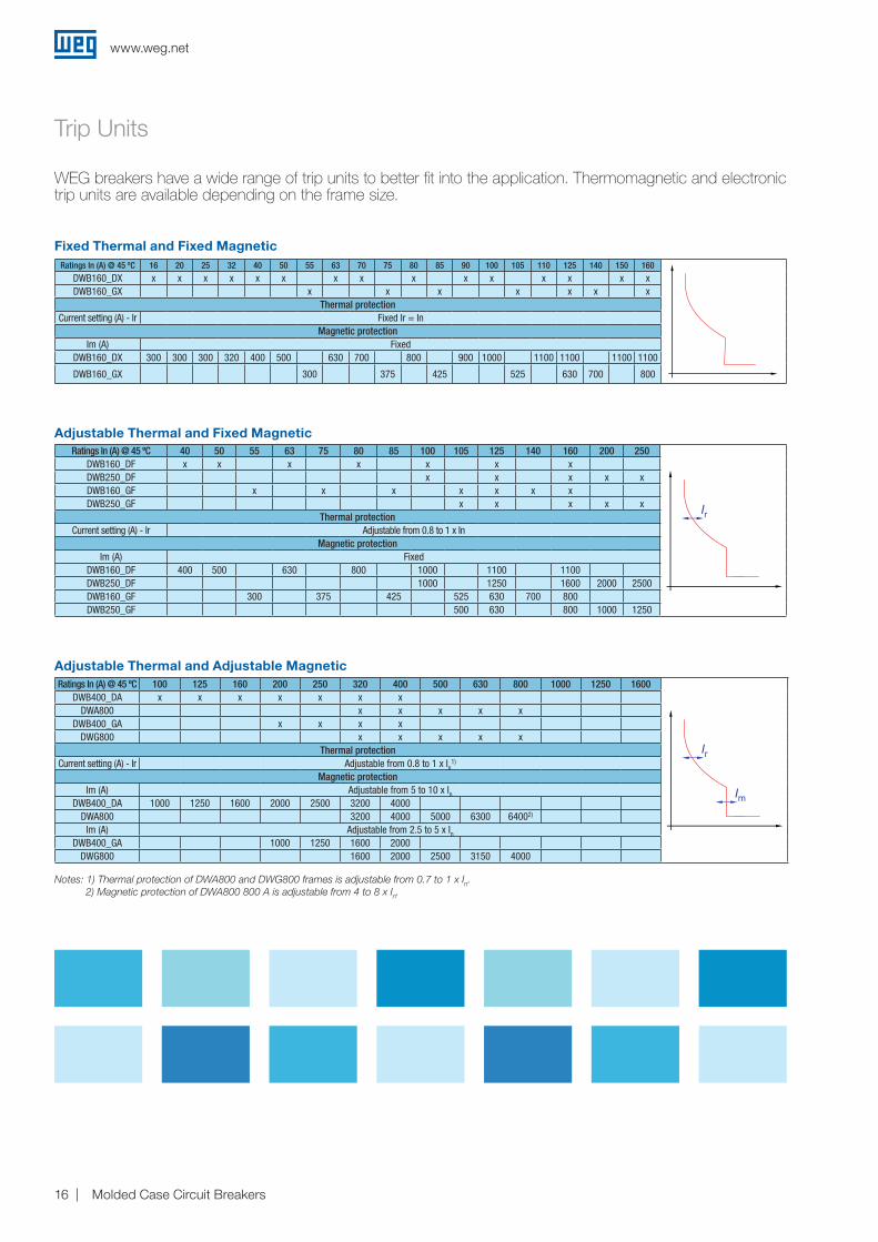
Trip Units
Ratings In (A) @ 45 ºC 16 20 25 32 40 50 55 63 70 75 80 85 90 100 105 110 125 140 150 160
Im
46
8
1012
2.7
.8
.9
.951
.65
6
7
810
4
.4
.5 3
2
I
x Inx In x Ir
L S
IiIr Is
.3.4
.1
.2.3
.2
.1
.4
70% 105%
3
1.6
12
18
6 at 8xIr (s)tr ts
2I t OFF
2I t ON
at 6xIr (s)
Is
Ii
ts
tr
Ir
Ir
Im
Ir
Curvas para Catálogo( Linha DW 2013 )
DWB160_DX x x x x x x x x x x x x x x xDWB160_GX x x x x x x x
Thermal protectionCurrent setting (A) - Ir Fixed Ir = In
Magnetic protectionIm (A) Fixed
DWB160_DX 300 300 300 320 400 500 630 700 800 900 1000 1100 1100 1100 1100
DWB160_GX 300 375 425 525 630 700 800
Ratings In (A) @ 45 ºC 40 50 55 63 75 80 85 100 105 125 140 160 200 250
Im
46
8
1012
2.7
.8
.9
.951
.65
6
7
810
4
.4
.5 3
2
I
x Inx In x Ir
L S
IiIr Is
.3.4
.1
.2.3
.2
.1
.4
70% 105%
3
1.6
12
18
6 at 8xIr (s)tr ts
2I t OFF
2I t ON
at 6xIr (s)
Is
Ii
ts
tr
Ir
Ir
Im
Ir
Curvas para Catálogo( Linha DW 2013 )
DWB160_DF x x x x x x xDWB250_DF x x x x xDWB160_GF x x x x x x xDWB250_GF x x x x x
Thermal protectionCurrent setting (A) - Ir Adjustable from 0.8 to 1 x In
Magnetic protectionIm (A) Fixed
DWB160_DF 400 500 630 800 1000 1100 1100DWB250_DF 1000 1250 1600 2000 2500DWB160_GF 300 375 425 525 630 700 800DWB250_GF 500 630 800 1000 1250
Ratings In (A) @ 45 ºC 100 125 160 200 250 320 400 500 630 800 1000 1250 1600
Im
46
8
1012
2.7
.8
.9
.951
.65
6
7
810
4
.4
.5 3
2
I
x Inx In x Ir
L S
IiIr Is
.3.4
.1
.2.3
.2
.1
.4
70% 105%
3
1.6
12
18
6 at 8xIr (s)tr ts
2I t OFF
2I t ON
at 6xIr (s)
Is
Ii
ts
tr
Ir
Ir
Im
Ir
Curvas para Catálogo( Linha DW 2013 )
DWB400_DA x x x x x x xDWA800 x x x x x
DWB400_GA x x x xDWG800 x x x x x
Thermal protectionCurrent setting (A) - Ir Adjustable from 0.8 to 1 x In
1)
Magnetic protectionIm (A) Adjustable from 5 to 10 x In
DWB400_DA 1000 1250 1600 2000 2500 3200 4000DWA800 3200 4000 5000 6300 64002)
Im (A) Adjustable from 2.5 to 5 x InDWB400_GA 1000 1250 1600 2000
DWG800 1600 2000 2500 3150 4000
Notes: 1) Thermal protection of DWA800 and DWG800 frames is adjustable from 0.7 to 1 x In.2) Magnetic protection of DWA800 800 A is adjustable from 4 to 8 x In.
WEG breakers have a wide range of trip units to better fit into the application. Thermomagnetic and electronic trip units are available depending on the frame size.
Fixed Thermal and Fixed Magnetic
Adjustable Thermal and Fixed Magnetic
Adjustable Thermal and Adjustable Magnetic
www.weg.net
Molded Case Circuit Breakers 17
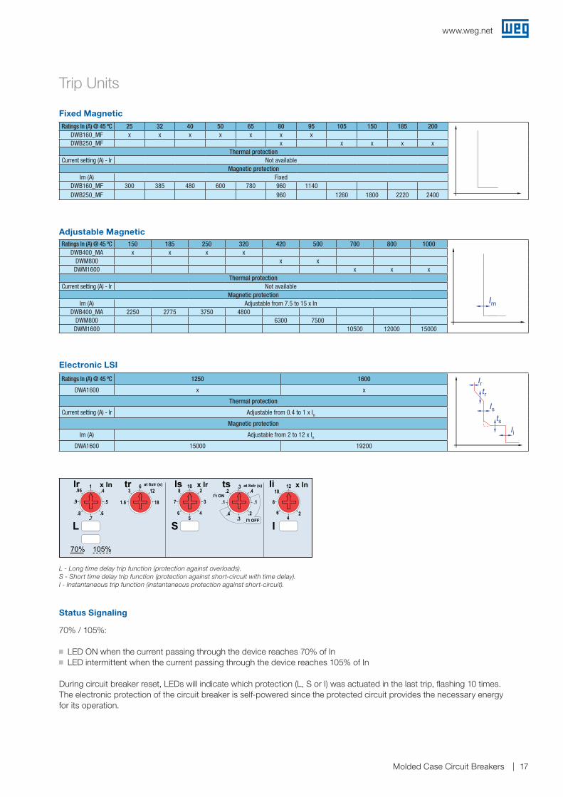
Trip Units
Ratings In (A) @ 45 ºC 25 32 40 50 65 80 95 105 150 185 200
Im
46
8
1012
2.7
.8
.9
.951
.65
6
7
810
4
.4
.5 3
2
I
x Inx In x Ir
L S
IiIr Is
.3.4
.1
.2.3
.2
.1
.4
70% 105%
3
1.6
12
18
6 at 8xIr (s)tr ts
2I t OFF
2I t ON
at 6xIr (s)
Is
Ii
ts
tr
Ir
Ir
Im
Ir
Curvas para Catálogo( Linha DW 2013 )
DWB160_MF x x x x x x xDWB250_MF x x x x x
Thermal protectionCurrent setting (A) - Ir Not available
Magnetic protectionIm (A) Fixed
DWB160_MF 300 385 480 600 780 960 1140DWB250_MF 960 1260 1800 2220 2400
Ratings In (A) @ 45 ºC 150 185 250 320 420 500 700 800 1000
Im
46
8
1012
2.7
.8
.9
.951
.65
6
7
810
4
.4
.5 3
2
I
x Inx In x Ir
L S
IiIr Is
.3.4
.1
.2.3
.2
.1
.4
70% 105%
3
1.6
12
18
6 at 8xIr (s)tr ts
2I t OFF
2I t ON
at 6xIr (s)
Is
Ii
ts
tr
Ir
Ir
Im
Ir
Curvas para Catálogo( Linha DW 2013 )
DWB400_MA x x x xDWM800 x x
DWM1600 x x xThermal protection
Current setting (A) - Ir Not availableMagnetic protection
Im (A) Adjustable from 7.5 to 15 x InDWB400_MA 2250 2775 3750 4800
DWM800 6300 7500DWM1600 10500 12000 15000
Im
46
8
1012
2.7
.8
.9
.951
.65
6
7
810
4
.4
.5 3
2
I
x Inx In x Ir
L S
IiIr Is
.3.4
.1
.2.3
.2
.1
.4
70% 105%
3
1.6
12
18
6 at 8xIr (s)tr ts
2I t OFF
2I t ON
at 6xIr (s)
Is
Ii
ts
tr
Ir
Ir
Im
Ir
Curvas para Catálogo( Linha DW 2013 )
Ratings In (A) @ 45 ºC 1250 1600
Im
46
8
1012
2.7
.8
.9
.951
.65
6
7
810
4
.4
.5 3
2
I
x Inx In x Ir
L S
IiIr Is
.3.4
.1
.2.3
.2
.1
.4
70% 105%
3
1.6
12
18
6 at 8xIr (s)tr ts
2I t OFF
2I t ON
at 6xIr (s)
Is
Ii
ts
tr
Ir
Ir
Im
Ir
Curvas para Catálogo( Linha DW 2013 )
DWA1600 x x
Thermal protection
Current setting (A) - Ir Adjustable from 0.4 to 1 x InMagnetic protection
Im (A) Adjustable from 2 to 12 x InDWA1600 15000 19200
Electronic LSI
L - Long time delay trip function (protection against overloads).S - Short time delay trip function (protection against short-circuit with time delay).I - Instantaneous trip function (instantaneous protection against short-circuit).
Fixed Magnetic
Adjustable Magnetic
Status Signaling
70% / 105%:
g LED ON when the current passing through the device reaches 70% of In g LED intermittent when the current passing through the device reaches 105% of In
During circuit breaker reset, LEDs will indicate which protection (L, S or I) was actuated in the last trip, flashing 10 times. The electronic protection of the circuit breaker is self-powered since the protected circuit provides the necessary energy for its operation.
www.weg.net
Molded Case Circuit Breakers18
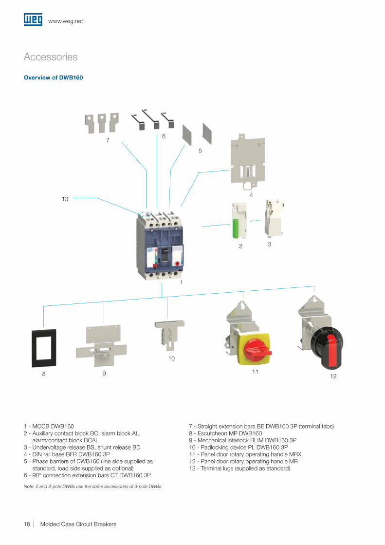
Overview of DWB160
Accessories
1 - MCCB DWB1602 - Auxiliary contact block BC, alarm block AL,
alarm/contact block BCAL3 - Undervoltage release BS, shunt release BD4 - DIN rail base BFR DWB160 3P5 - Phase barriers of DWB160 (line side supplied as
standard, load side supplied as optional)6 - 90° connection extension bars CT DWB160 3P
7 - Straight extension bars BE DWB160 3P (terminal tabs) 8 - Escutcheon MP DWB1609 - Mechanical interlock BLIM DWB160 3P10 - Padlocking device PL DWB160 3P11 - Panel door rotary operating handle MRX12 - Panel door rotary operating handle MR13 - Terminal lugs (supplied as standard)
32
1
4
5
67
13
12118 9
10
Note: 2 and 4-pole DWBs use the same accessories of 3-pole DWBs.
www.weg.net
Molded Case Circuit Breakers 19
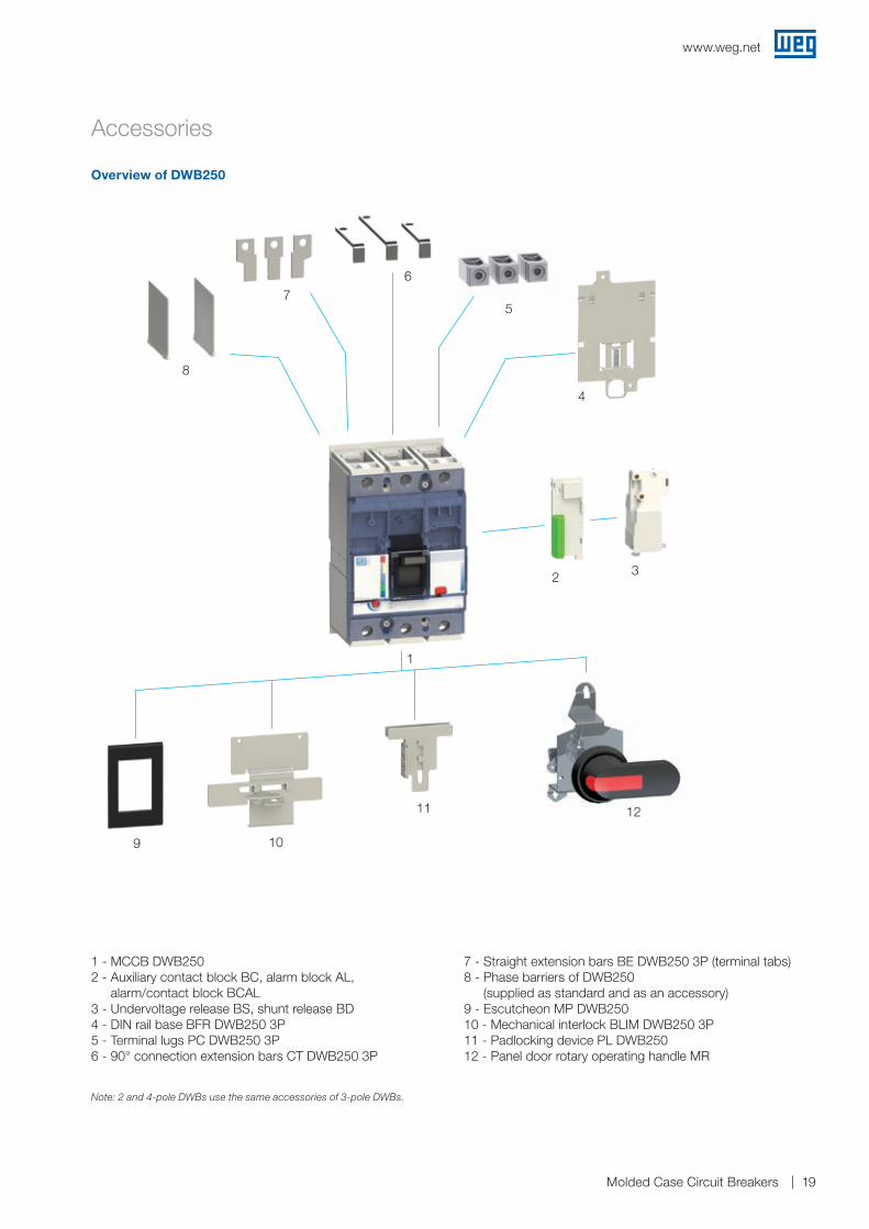
Overview of DWB250
Accessories
1 - MCCB DWB2502 - Auxiliary contact block BC, alarm block AL,
alarm/contact block BCAL3 - Undervoltage release BS, shunt release BD4 - DIN rail base BFR DWB250 3P5 - Terminal lugs PC DWB250 3P6 - 90° connection extension bars CT DWB250 3P
7 - Straight extension bars BE DWB250 3P (terminal tabs) 8 - Phase barriers of DWB250
(supplied as standard and as an accessory)9 - Escutcheon MP DWB25010 - Mechanical interlock BLIM DWB250 3P11 - Padlocking device PL DWB25012 - Panel door rotary operating handle MR
3
1
2
4
5
67
8
12
9 10
11
Note: 2 and 4-pole DWBs use the same accessories of 3-pole DWBs.
www.weg.net
Molded Case Circuit Breakers20
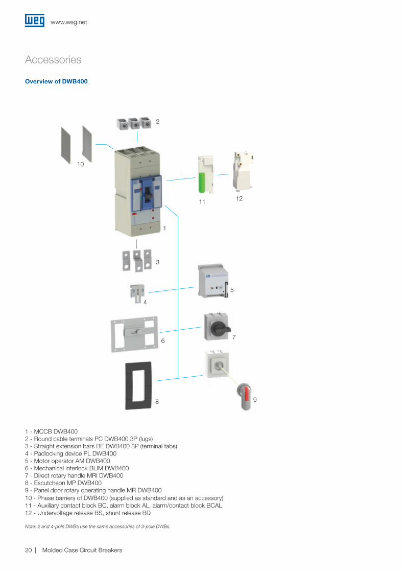
Overview of DWB400
Accessories
1 - MCCB DWB4002 - Round cable terminals PC DWB400 3P (lugs)3 - Straight extension bars BE DWB400 3P (terminal tabs)4 - Padlocking device PL DWB4005 - Motor operator AM DWB4006 - Mechanical interlock BLIM DWB4007 - Direct rotary handle MRI DWB4008 - Escutcheon MP DWB4009 - Panel door rotary operating handle MR DWB40010 - Phase barriers of DWB400 (supplied as standard and as an accessory)11 - Auxiliary contact block BC, alarm block AL, alarm/contact block BCAL12 - Undervoltage release BS, shunt release BD
2
1
3
10
4
6
8 9
7
5
Note: 2 and 4-pole DWBs use the same accessories of 3-pole DWBs.
1211
www.weg.net
Molded Case Circuit Breakers 21
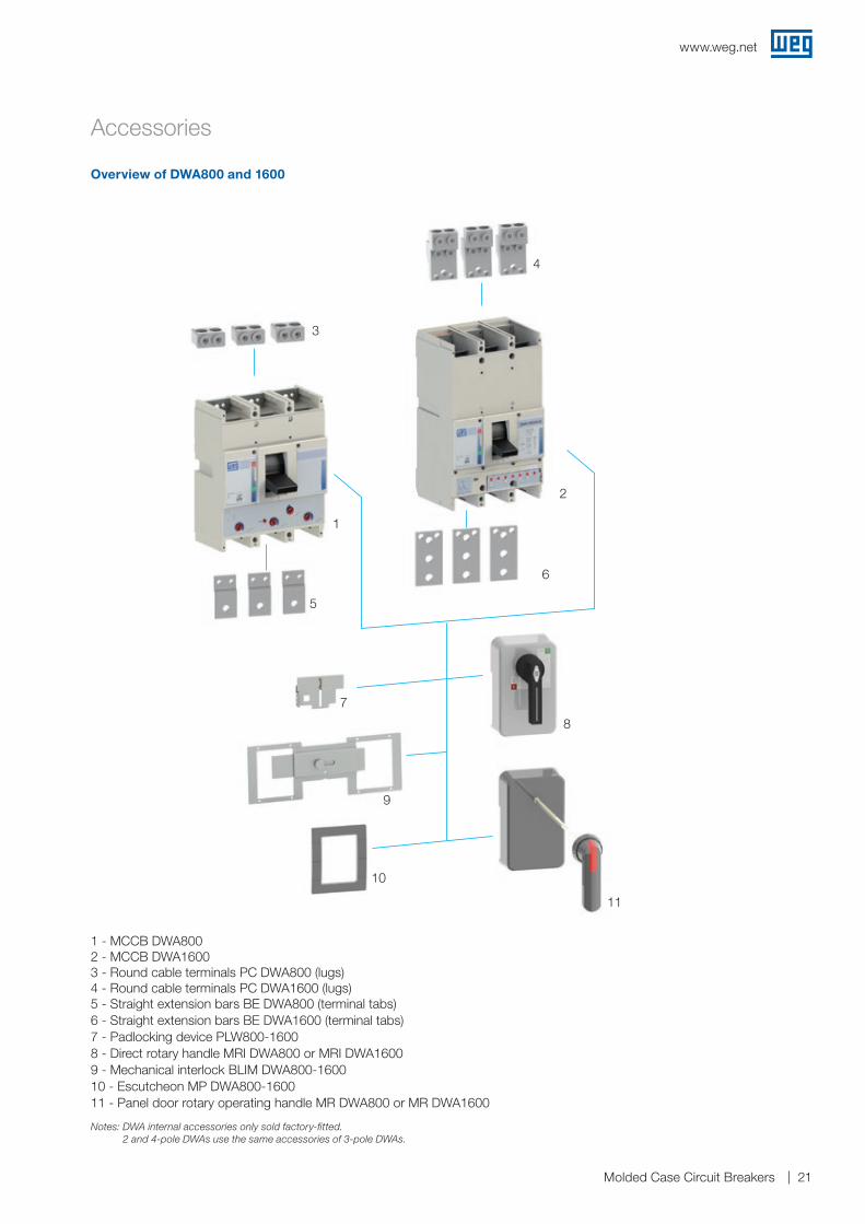
Overview of DWA800 and 1600
Accessories
1 - MCCB DWA8002 - MCCB DWA16003 - Round cable terminals PC DWA800 (lugs)4 - Round cable terminals PC DWA1600 (lugs)5 - Straight extension bars BE DWA800 (terminal tabs)6 - Straight extension bars BE DWA1600 (terminal tabs)7 - Padlocking device PLW800-16008 - Direct rotary handle MRI DWA800 or MRI DWA16009 - Mechanical interlock BLIM DWA800-160010 - Escutcheon MP DWA800-160011 - Panel door rotary operating handle MR DWA800 or MR DWA1600
3
1
5
7
9
10
11
8
6
2
4
Notes: DWA internal accessories only sold factory-fitted. 2 and 4-pole DWAs use the same accessories of 3-pole DWAs.
www.weg.net
Molded Case Circuit Breakers22
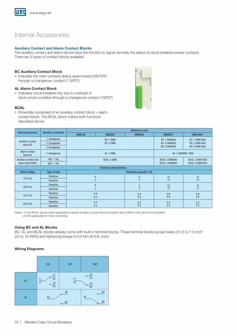
Internal Accessories
BC Auxiliary Contact Blockg Indicates the main contacts status open/closed (ON/OFF)
through a changeover contact (1 SPDT)
AL Alarm Contact Blockg Indicates circuit breakers trip due to overload or
short-circuit condition through a changeover contact (1SPDT)
BCALg Ensemble comprised of an auxiliary contact block + alarm
contact block. The BCAL block makes both functions described above
Internal accessory Number of contactsReference code
DWB160 DWB250 DWB400 DWA8001) DWA16001)
Auxiliary contact block BC
1 changeover BC-1 DWBBC-2 DWB
-
BC-1 DWA800BC-2 DWA800BC-3 DWA800
BC-1 DWA1600BC-2 DWA1600BC-3 DWA1600
2 changeover
3 changeover
Alarm contact block AL
1 changeover AL-1 DWB AL-1 DWA800-1600
Auxiliary contact and alarm block BCAL
1BC + 1AL BCAL-2 DWB-
BCAL-2 DWA800BCAL-3 DWA800
BCAL-2 DWA1600BCAL-3 DWA16002BC + 1AL
Electrical characteristics
Rated voltage Type of load Switching capacity ²) (A)
125 V acResistive 6
353
1512
1512Inductive
250 V acResistive 6
332
1512
1512Inductive
125 V dcResistive 0.4
0.20.40.2
0.60.6
0.60.6Inductive
250 V dcResistive 0.2
0.20.20.2
0.30.3
0.30.3Inductive
Notes: 1) Use BCAL blocks when applications require auxiliary contact block and alarm block fitted in the same circuit breaker.2) Not applicable for motor switching.
Auxiliary Contact and Alarm Contact BlocksThe auxiliary contact and alarm blocks have the function to signal remotely the status of circuit breakers power contacts. There are 3 types of contact blocks available:
Using BC and AL BlocksBC, AL and BCAL blocks already come with built-in terminal blocks. These terminal blocks accept wires of 0.5 to 1.5 mm² (20 to 16 AWG) and tightening torque of 0.8 Nm (6.9 lb. inch).
Wiring Diagrams
ON OFF TRIP
BC
AL
1112221424
21
81
82
84
11
1222
1424
21
81
82
84
www.weg.net
Molded Case Circuit Breakers 23
Reference code
Rated voltage (Ue) Voltage code DWB160 / DWB250 Consumption DWB400 DWA800 DWA1600 Consumption
BS undervoltage release
110/127 V ac D60 BS DWB400 D60 BS D60 DWA800 BS D60 DWA1600 5 VA
220/240 V ac D66 BS DWB400 D66 BS D66 DWA800 BS D66 DWA1600 5 VA
380-415 V ac D70 BS DWB400 D70 BS D70 DWA800 BS D70 DWA1600 5 VA
440-480 V ac D74 BS DWB400 D74 BS D74 DWA800 BS D74 DWA1600 5 VA
24 V dc C03 BS DWB400 C03 BS C03 DWA800 BS C03 DWA1600 1 W
48 V dc C07 BS DWB400 C07 BS C07 DWA800 BS C07 DWA1600 1 W
125 V dc C13 BS C13 DWA800 BS C13 DWA1600 4 W
24 V ac / V dc E26 BS DWB160-250 E26 1.5 VA
48 V ac / V dc E27 BS DWB160-250 E27 1.5 VA
60 V ac / V dc E28 BS DWB160-250 E28 1.5 VA
110/130 V ac / V dc E10 BS DWB160-250 E10 1.5 VA
220/250 V ac / V dc E15 BS DWB160-250 E15 1.5 VA
BD shunt release
24 V ac / V dc E26 BD DWB160-250 E26 150 VA BD DWB400 E26 BD E26 DWA800 BD E26 DWA1600 65 VA
48 V ac / V dc E27 BD DWB160-250 E27 150 VA BD DWB400 E27 BD E27 DWA800 BD E27 DWA1600 65 VA
60 V ac / V dc E28 BD DWB160-250 E28 150 VA
110/130 V ac / V dc E10 BD DWB160-250 E10 150 VA BD DWB400 E10 BD E10 DWA800 BD E10 DWA1600 65 VA
220/250 V ac / V dc E15 BD DWB160-250 E15 150 VA BD DWB400 E15 BD E15 DWA800 BD E15 DWA1600 65 VA
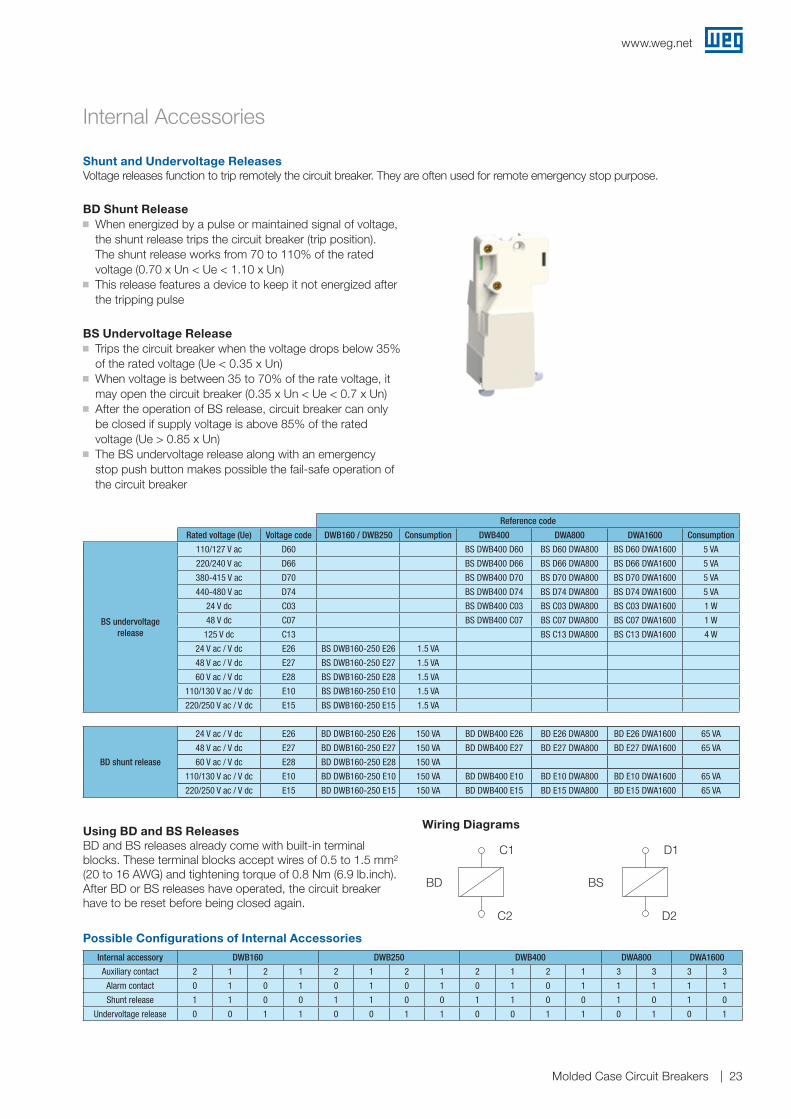
Internal Accessories
Shunt and Undervoltage ReleasesVoltage releases function to trip remotely the circuit breaker. They are often used for remote emergency stop purpose.
BD Shunt Releaseg When energized by a pulse or maintained signal of voltage,
the shunt release trips the circuit breaker (trip position). The shunt release works from 70 to 110% of the rated voltage (0.70 x Un < Ue < 1.10 x Un)
g This release features a device to keep it not energized after the tripping pulse
BS Undervoltage Releaseg Trips the circuit breaker when the voltage drops below 35%
of the rated voltage (Ue < 0.35 x Un)g When voltage is between 35 to 70% of the rate voltage, it
may open the circuit breaker (0.35 x Un < Ue < 0.7 x Un)g After the operation of BS release, circuit breaker can only
be closed if supply voltage is above 85% of the rated voltage (Ue > 0.85 x Un)
g The BS undervoltage release along with an emergency stop push button makes possible the fail-safe operation of the circuit breaker
Using BD and BS ReleasesBD and BS releases already come with built-in terminal blocks. These terminal blocks accept wires of 0.5 to 1.5 mm² (20 to 16 AWG) and tightening torque of 0.8 Nm (6.9 lb.inch). After BD or BS releases have operated, the circuit breaker have to be reset before being closed again.
Wiring Diagrams
D1
BS
D2
C1
C2
BD
Possible Configurations of Internal Accessories
Internal accessory DWB160 DWB250 DWB400 DWA800 DWA1600
Auxiliary contact 2 1 2 1 2 1 2 1 2 1 2 1 3 3 3 3
Alarm contact 0 1 0 1 0 1 0 1 0 1 0 1 1 1 1 1
Shunt release 1 1 0 0 1 1 0 0 1 1 0 0 1 0 1 0
Undervoltage release 0 0 1 1 0 0 1 1 0 0 1 1 0 1 0 1
C1 D1
BD BS
C2 D2
www.weg.net
Molded Case Circuit Breakers24
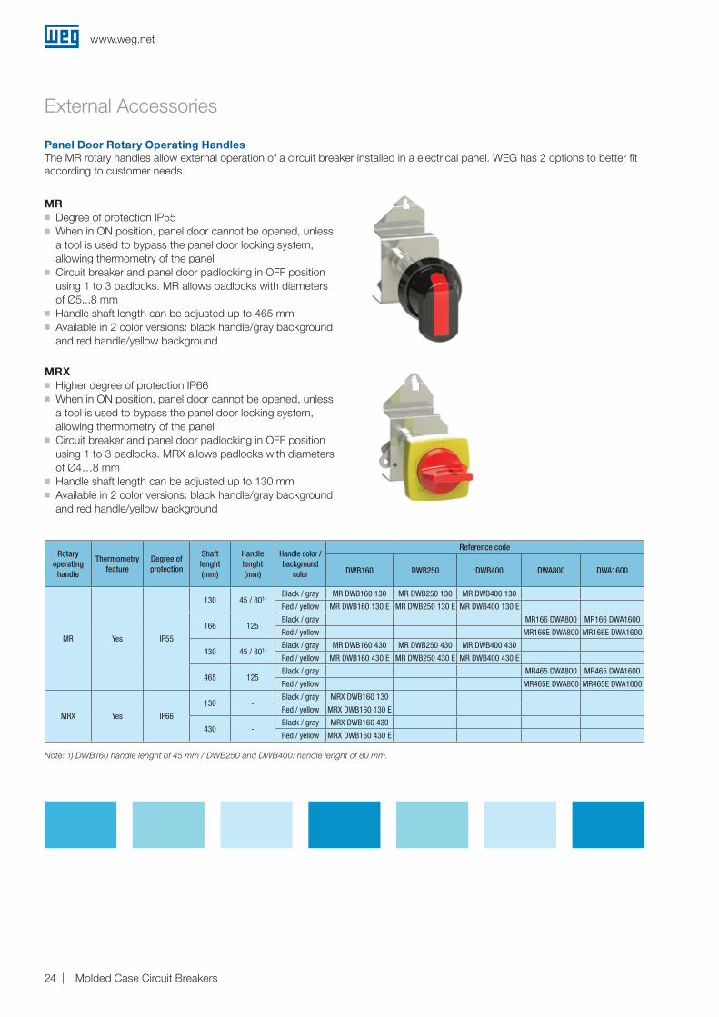
External Accessories
Panel Door Rotary Operating HandlesThe MR rotary handles allow external operation of a circuit breaker installed in a electrical panel. WEG has 2 options to better fit according to customer needs.
MRg Degree of protection IP55g When in ON position, panel door cannot be opened, unless
a tool is used to bypass the panel door locking system, allowing thermometry of the panel
g Circuit breaker and panel door padlocking in OFF position using 1 to 3 padlocks. MR allows padlocks with diameters of Ø5...8 mm
g Handle shaft length can be adjusted up to 465 mmg Available in 2 color versions: black handle/gray background
and red handle/yellow background
MRXg �Higher degree of protection IP66g When in ON position, panel door cannot be opened, unless
a tool is used to bypass the panel door locking system, allowing thermometry of the panel
g Circuit breaker and panel door padlocking in OFF position using 1 to 3 padlocks. MRX allows padlocks with diameters of Ø4…8 mm
g Handle shaft length can be adjusted up to 130 mmg Available in 2 color versions: black handle/gray background
and red handle/yellow background
Note: 1) DWB160 handle lenght of 45 mm / DWB250 and DWB400: handle lenght of 80 mm.
Rotary operating
handle
Thermometry feature
Degree of protection
Shaft lenght (mm)
Handle lenght (mm)
Handle color / background
color
Reference code
DWB160 DWB250 DWB400 DWA800 DWA1600
MR Yes IP55
130 45 / 801)Black / gray MR DWB160 130 MR DWB250 130 MR DWB400 130
Red / yellow MR DWB160 130 E MR DWB250 130 E MR DWB400 130 E
166 125Black / gray MR166 DWA800 MR166 DWA1600
Red / yellow MR166E DWA800 MR166E DWA1600
430 45 / 801)Black / gray MR DWB160 430 MR DWB250 430 MR DWB400 430
Red / yellow MR DWB160 430 E MR DWB250 430 E MR DWB400 430 E
465 125Black / gray MR465 DWA800 MR465 DWA1600
Red / yellow MR465E DWA800 MR465E DWA1600
MRX Yes IP66
130 -Black / gray MRX DWB160 130
Red / yellow MRX DWB160 130 E
430 -Black / gray MRX DWB160 430
Red / yellow MRX DWB160 430 E
www.weg.net
Molded Case Circuit Breakers 25
External Accessories
Direct rotary operating handle
Thermometry feature Degree of protectionHandle color/
Background colorReference code
DWB400 DWA800 DWA1600
MRI No IP20 Black/Gray MRI DWB400 MRI DWA800 MRI DWA1600
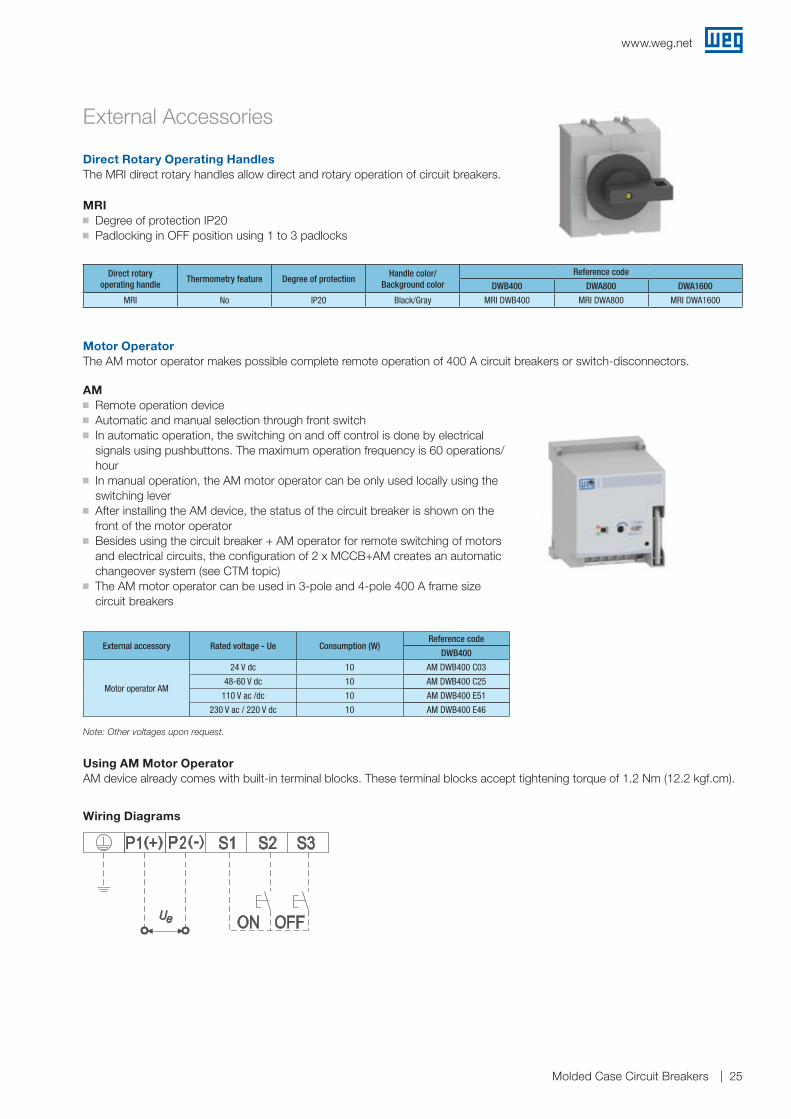
Direct Rotary Operating HandlesThe MRI direct rotary handles allow direct and rotary operation of circuit breakers.
MRIg Degree of protection IP20g Padlocking in OFF position using 1 to 3 padlocks
Motor OperatorThe AM motor operator makes possible complete remote operation of 400 A circuit breakers or switch-disconnectors.
AMg Remote operation deviceg Automatic and manual selection through front switchg In automatic operation, the switching on and off control is done by electrical
signals using pushbuttons. The maximum operation frequency is 60 operations/hour
g In manual operation, the AM motor operator can be only used locally using the switching lever
g After installing the AM device, the status of the circuit breaker is shown on the front of the motor operator
g Besides using the circuit breaker + AM operator for remote switching of motors and electrical circuits, the configuration of 2 x MCCB+AM creates an automatic changeover system (see CTM topic)
g The AM motor operator can be used in 3-pole and 4-pole 400 A frame size circuit breakers
External accessory Rated voltage - Ue Consumption (W)Reference code
DWB400
Motor operator AM
24 V dc 10 AM DWB400 C03
48-60 V dc 10 AM DWB400 C25
110 V ac /dc 10 AM DWB400 E51
230 V ac / 220 V dc 10 AM DWB400 E46
Note: Other voltages upon request.
Using AM Motor OperatorAM device already comes with built-in terminal blocks. These terminal blocks accept tightening torque of 1.2 Nm (12.2 kgf.cm).
Wiring Diagrams
S1 S2 S3
Ue ON OFF
www.weg.net
Molded Case Circuit Breakers26
External Accessories
Changeover DevicesManual-operated or automatic changeovers are used to make safe switching of two different circuits.
External accessory MCCB Reference code
Mechanical interlock BLIM
DWB160 3P BLIM DWB160 3P
DWB160 4P BLIM DWB160 4P
DWB250 3P BLIM DWB250 3P
DWB250 4P BLIM DWB250 4P
DWB400 3P BLIM DWB400 3P
DWB400 4P BLIM DWB400 4P
DWA800 3P / DWA1600 3P BLIM DWA800-1600
DWA800 4P / DWA1600 4P BLIM DWA800-1600 4P
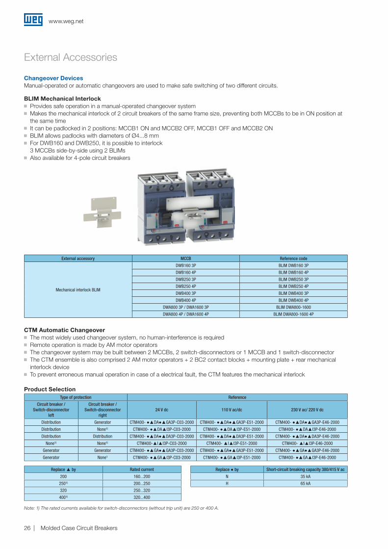
BLIM Mechanical Interlock g Provides safe operation in a manual-operated changeover systemg Makes the mechanical interlock of 2 circuit breakers of the same frame size, preventing both MCCBs to be in ON position at
the same timeg It can be padlocked in 2 positions: MCCB1 ON and MCCB2 OFF, MCCB1 OFF and MCCB2 ONg BLIM allows padlocks with diameters of Ø4...8 mmg For DWB160 and DWB250, it is possible to interlock
3 MCCBs side-by-side using 2 BLIMsg Also available for 4-pole circuit breakers
CTM Automatic Changeover g The most widely used changeover system, no human-interference is requiredg Remote operation is made by AM motor operatorsg The changeover system may be built between 2 MCCBs, 2 switch-disconnectors or 1 MCCB and 1 switch-disconnectorg The CTM ensemble is also comprised 2 AM motor operators + 2 BC2 contact blocks + mounting plate + rear mechanical
interlock deviceg To prevent erroneous manual operation in case of a electrical fault, the CTM features the mechanical interlock
Type of protection Reference
Circuit breaker /Switch-disconnector
left
Circuit breaker /Switch-disconnector
right24 V dc 110 V ac/dc 230 V ac/ 220 V dc
Distribution Generator CTM400- ●▲DA●▲GA3P-C03-2000 CTM400- ●▲DA●▲GA3P-E51-2000 CTM400- ●▲DA●▲GA3P-E46-2000
Distribution None¹) CTM400- ●▲DA▲I3P-C03-2000 CTM400- ●▲DA▲I3P-E51-2000 CTM400- ●▲DA▲I3P-E46-2000
Distribution Distribution CTM400- ●▲DA●▲DA3P-C03-2000 CTM400- ●▲DA●▲DA3P-E51-2000 CTM400- ●▲DA●▲DA3P-E46-2000
None¹) None¹) CTM400-▲I▲I3P-C03-2000 CTM400- ▲I▲I3P-E51-2000 CTM400- ▲I▲I3P-E46-2000
Generator Generator CTM400- ●▲GA●▲GA3P-C03-2000 CTM400- ●▲GA●▲GA3P-E51-2000 CTM400- ●▲GA●▲GA3P-E46-2000
Generator None¹ CTM400- ●▲GA▲I3P-C03-2000 CTM400- ●▲GA▲I3P-E51-2000 CTM400- ●▲GA▲I3P-E46-2000
Product Selection
Note: 1) The rated currents available for switch-disconnectors (without trip unit) are 250 or 400 A.
Replace ● by Short-circuit breaking capacity 380/415 V ac
N 35 kA
H 65 kA
Replace ▲ by Rated current
200 160...200
250¹) 200...250
320 250...320
400¹) 320...400
www.weg.net
Molded Case Circuit Breakers 27
External Accessories
Accessories for Connection and InstallationDepending on the application and local standards, the MCCB may be installed in several positions in a panel and connected through busbars or cables. Given these requirements, the DWA and DWB range of circuit breakers have the specific connection accessories to comply with.
External accessory MCCB Supplied with (units) Maximum cross-section (mm²) Reference code
Straight extension busbar BE
DWB160 3P 3
See installation and connections on page 6.
BE DWB160 3P
DWB160 4P 4 BE DWB160 4P
DWB250 3P 3 BE DWB250 3P
DWB250 4P 4 BE DWB250 4P
DWB400 3P 3 BE DWB400 3P
DWB400 4P 4 BE DWB400 4P
DWA800 3P 3 BE DWA800
DWA800 4P 4 BE DWA800-4P
DWA1600 3P (up to 1250 A) 3 BE DWA1600-1250
DWA1600 4P (up to 1250 A) 4 BE DWA1600-1250-4P
DWA1600 3 BE DWA1600
DWA1600-4P 4 BE DWA1600-4P
90° extension bar CT
DWB160 3P 3
See installation and connections on page 6.
CT DWB160 3P
DWB160 4P 4 CT DWB160 4P
DWB250 3P 3 CT DWB250 3P
DWB250 4P 4 CT DWB250 4P
DWB400 3P 3 CT DWB400 3P
DWB400 4P 4 CT DWB400 4P
DWA800 3P / 4P 3 CT DWA800
DWA1600 3P / 4P 3 CT DWA1600
Round cable terminal PC
DWB250 3P 3 120 (1 cable) PC DWB250 3P
DWB250 4P 4 120 (1 cable) PC DWB250 4P
DWB400 3P 3 240 (1 cable) PC DWB400 3P
DWB400 4P 4 240 (1 cable) PC DWB400 4P
DWA800 3P / 4P 3 240 (2 cables) PC DWA800
DWA1600 3P / 4P 3 240 (4 cables) PC DWA1600
DIN rail base BFR1)DWB160 3P 1 N/A BFR DWB160
DWB250 3P 1 N/A BFR DWB250
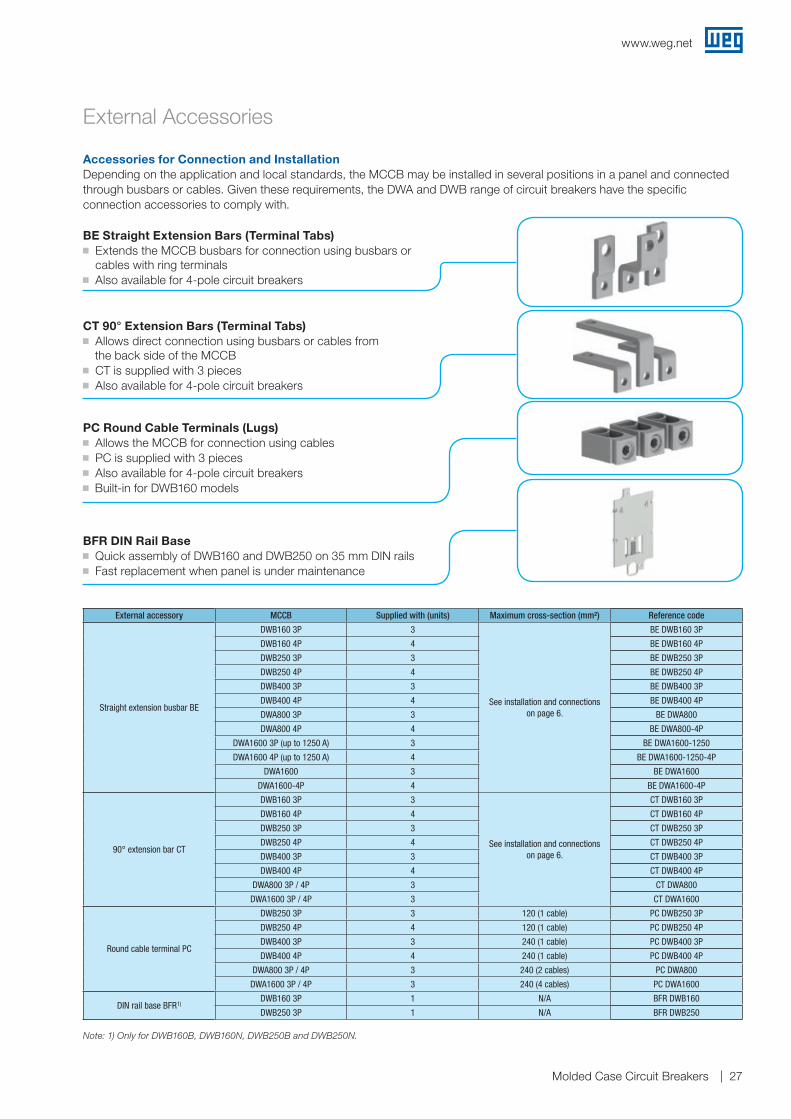
BE Straight Extension Bars (Terminal Tabs)g Extends the MCCB busbars for connection using busbars or
cables with ring terminalsg �Also available for 4-pole circuit breakers
CT 90° Extension Bars (Terminal Tabs)g Allows direct connection using busbars or cables from the back side of the MCCBg CT is supplied with 3 piecesg Also available for 4-pole circuit breakers
PC Round Cable Terminals (Lugs)g Allows the MCCB for connection using cablesg PC is supplied with 3 piecesg Also available for 4-pole circuit breakers
g Built-in for DWB160 models
BFR DIN Rail Baseg Quick assembly of DWB160 and DWB250 on 35 mm DIN railsg Fast replacement when panel is under maintenance
Note: 1) Only for DWB160B, DWB160N, DWB250B and DWB250N.
www.weg.net
Molded Case Circuit Breakers28
External Accessories
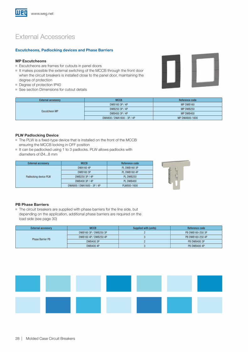
MP Escutcheons g Escutcheons are frames for cutouts in panel doors g It makes possible the external switching of the MCCB through the front door when the circuit breakers is installed close to the panel door, maintaining the degree of protection
g Degree of protection IP40 g See section Dimensions for cutout details
Escutcheons, Padlocking devices and Phase Barriers
External accessory MCCB Reference code
Escutcheon MP
DWB160 3P / 4P MP DWB160
DWB250 3P / 4P MP DWB250
DWB400 3P / 4P MP DWB400
DWA800 / DWA1600 - 3P / 4P MP DWA800-1600
External accessory MCCB Supplied with (units) Reference code
Phase Barrier PB
DWB160 3P / DWB250 3P 2 PB DWB160-250 3P
DWB160 4P / DWB250 4P 3 PB DWB160-250 4P
DWB400 3P 2 PB DWB400 3P
DWB400 4P 3 PB DWB400 4P
External accessory MCCB Reference code
Padlocking device PLW
DWA160 4P PL DWB160 3P
DWB160 3P PL DWB160 4P
DWB250 3P / 4P PL DWB250
DWB400 3P / 4P PL DWB400
DWA800 / DWA1600 - 3P / 4P PLW800-1600
PLW Padlocking Device g The PLW is a fixed-type device that is installed on the front of the MCCB ensuring the MCCB locking in OFF position
g It can be padlocked using 1 to 3 padlocks. PLW allows padlocks with diameters of Ø4...8 mm
PB Phase Barriers g The circuit breakers are supplied with phase barriers for the line side, but depending on the application, additional phase barriers are required on the load side (see page 30)
www.weg.net
Molded Case Circuit Breakers 29
Installation and Connections
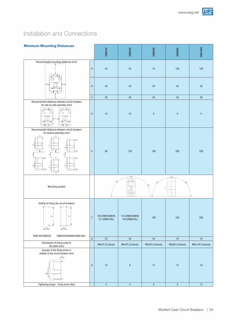
Minimum Mounting Distances
DWB1
60
DWB2
50
DWB4
00
DWA8
00
DWA1
600
Recommended mounting distances (mm)
A 50 50 70 100 100
B 20 20 30 30 30
C 20 20 30 30 30
Recommended distances between circuit breakersfor side by side assembly (mm)
D 10 10 0 0 0
Recommended distances between circuit breakersfor vertical assembly (mm)
E 90 150 180 200 200
Mounting position
Drilling for fixing the circuit breakers
DWB160/DWB250 DWB400/DWA800/DWA1600
F100 (DWB160B/N) 121 (DWB160L)
124 (DWB250B/N) 149 (DWB250L)
199 230 265
G 25 35 35 70 70
Dimensions of fixing screw tothe plate (mm)
M4x70 (2 pieces) M4x70 (2 pieces) M5x50 (4 pieces) M5x60 (4 pieces) M8x140 (4 pieces)
Surpass of the fixing screw inrelation to the circuit breaker (mm)
H 10 8 15 15 18
Tightening torque - fixing screw (Nm) 4 4 5 5 12
E E E
BB
AC
D
90°
90°
90° 90°
H
www.weg.net
Molded Case Circuit Breakers30
Installation and Connections
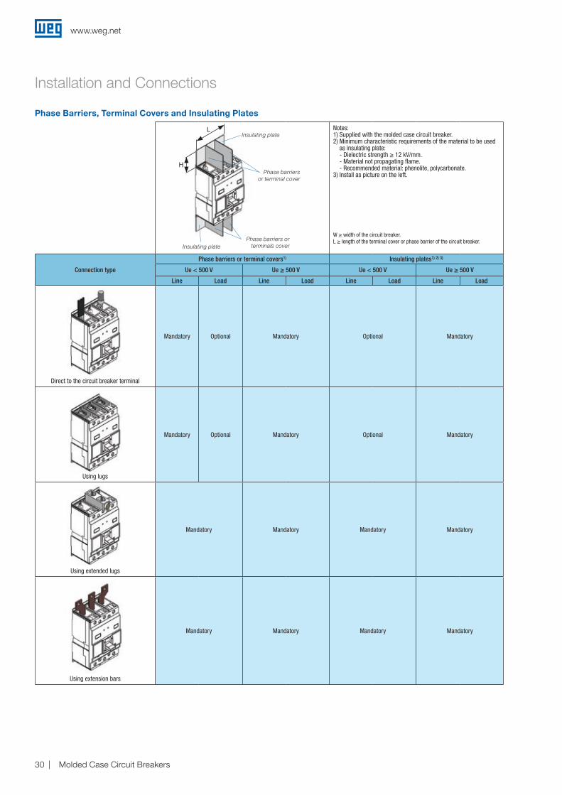
Phase Barriers, Terminal Covers and Insulating Plates
Notes: 1) Supplied with the molded case circuit breaker.2) Minimum characteristic requirements of the material to be used
as insulating plate: - Dielectric strength ≥ 12 kV/mm. - Material not propagating flame. - Recommended material: phenolite, polycarbonate.3) Install as picture on the left.
W ≥ width of the circuit breaker.L ≥ length of the terminal cover or phase barrier of the circuit breaker.
Connection type
Phase barriers or terminal covers1) Insulating plates1) 2) 3)
Ue < 500 V Ue ≥ 500 V Ue < 500 V Ue ≥ 500 V
Line Load Line Load Line Load Line Load
L
H
E
D
C
B
A
1 2 3 4 5 6
Propriedade da WEG. Proibida reprodução sem autorização prévia./ WEG's property. Forbidden reproduction without previous authorization.
MASSA LÍQUIDA/NET WEIGHT
DATALIBERADOVERIFICADOEXECUTADO
DT LIBER/REL DT
LIBER/RELEASED
EXEC
VERIF/CHECKED
RESUMO DE MODIFICAÇÕES
11
EXECUTED VERDATERELEASED
FOL/SHEET
LOC SUMMARY OF MODIFICATIONSECM
SWD
- A3
ESCALA/SCALEMASSA BRUTA/GROSS WEIGHT
CHECKED
Direct to the circuit breaker terminal
Mandatory Optional Mandatory Optional Mandatory
L
H
E
D
C
B
A
1 2 3 4 5 6
Propriedade da WEG. Proibida reprodução sem autorização prévia./ WEG's property. Forbidden reproduction without previous authorization.
MASSA LÍQUIDA/NET WEIGHT
DATALIBERADOVERIFICADOEXECUTADO
DT LIBER/REL DT
LIBER/RELEASED
EXEC
VERIF/CHECKED
RESUMO DE MODIFICAÇÕES
11
EXECUTED VERDATERELEASED
FOL/SHEET
LOC SUMMARY OF MODIFICATIONSECM
SWD
- A3
ESCALA/SCALEMASSA BRUTA/GROSS WEIGHT
CHECKEDUsing lugs
Mandatory Optional Mandatory Optional Mandatory
L
H
E
D
C
B
A
1 2 3 4 5 6
Propriedade da WEG. Proibida reprodução sem autorização prévia./ WEG's property. Forbidden reproduction without previous authorization.
MASSA LÍQUIDA/NET WEIGHT
DATALIBERADOVERIFICADOEXECUTADO
DT LIBER/REL DT
LIBER/RELEASED
EXEC
VERIF/CHECKED
RESUMO DE MODIFICAÇÕES
11
EXECUTED VERDATERELEASED
FOL/SHEET
LOC SUMMARY OF MODIFICATIONSECM
SWD
- A3
ESCALA/SCALEMASSA BRUTA/GROSS WEIGHT
CHECKED
Using extended lugs
Mandatory Mandatory Mandatory Mandatory
L
H
E
D
C
B
A
1 2 3 4 5 6
Propriedade da WEG. Proibida reprodução sem autorização prévia./ WEG's property. Forbidden reproduction without previous authorization.
MASSA LÍQUIDA/NET WEIGHT
DATALIBERADOVERIFICADOEXECUTADO
DT LIBER/REL DT
LIBER/RELEASED
EXEC
VERIF/CHECKED
RESUMO DE MODIFICAÇÕES
11
EXECUTED VERDATERELEASED
FOL/SHEET
LOC SUMMARY OF MODIFICATIONSECM
SWD
- A3
ESCALA/SCALEMASSA BRUTA/GROSS WEIGHT
CHECKED
Using extension bars
Mandatory Mandatory Mandatory Mandatory
H
L
H
E
D
C
B
A
1 2 3 4 5 6
Propriedade da WEG. Proibida reprodução sem autorização prévia./ WEG's property. Forbidden reproduction without previous authorization.
MASSA LÍQUIDA/NET WEIGHT
DATALIBERADOVERIFICADOEXECUTADO
DT LIBER/REL DT
LIBER/RELEASED
EXEC
VERIF/CHECKED
RESUMO DE MODIFICAÇÕES
11
EXECUTED VERDATERELEASED
FOL/SHEET
LOC SUMMARY OF MODIFICATIONSECM
SWD
- A3
ESCALA/SCALEMASSA BRUTA/GROSS WEIGHT
CHECKED
Insulating plate
Insulating plate
Phase barriers orterminals cover
Phase barriersor terminal cover
L
www.weg.net
Molded Case Circuit Breakers 31
Installation and Connections
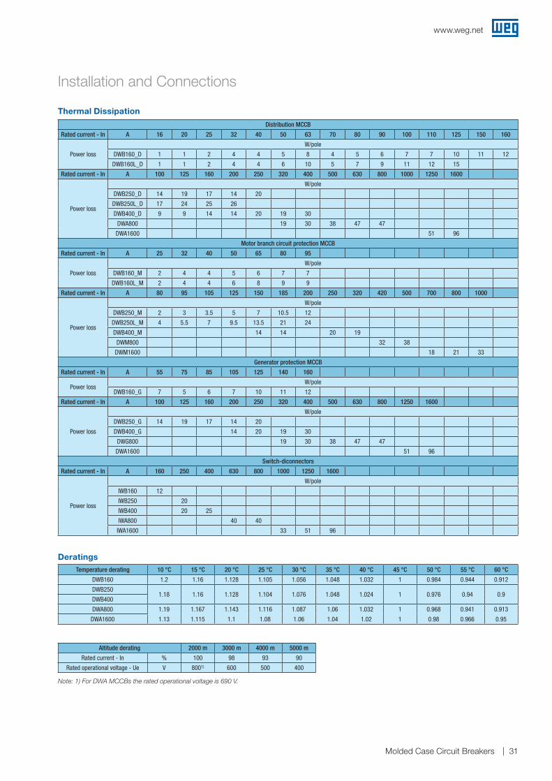
Thermal Dissipation
Deratings
Distribution MCCB
Rated current - In A 16 20 25 32 40 50 63 70 80 90 100 110 125 150 160
Power loss
W/pole
DWB160_D 1 1 2 4 4 5 8 4 5 6 7 7 10 11 12
DWB160L_D 1 1 2 4 4 6 10 5 7 9 11 12 15
Rated current - In A 100 125 160 200 250 320 400 500 630 800 1000 1250 1600
Power loss
W/pole
DWB250_D 14 19 17 14 20
DWB250L_D 17 24 25 26
DWB400_D 9 9 14 14 20 19 30
DWA800 19 30 38 47 47
DWA1600 51 96
Motor branch circuit protection MCCB
Rated current - In A 25 32 40 50 65 80 95
Power loss
W/pole
DWB160_M 2 4 4 5 6 7 7
DWB160L_M 2 4 4 6 8 9 9
Rated current - In A 80 95 105 125 150 185 200 250 320 420 500 700 800 1000
Power loss
W/pole
DWB250_M 2 3 3.5 5 7 10.5 12
DWB250L_M 4 5.5 7 9.5 13.5 21 24
DWB400_M 14 14 20 19
DWM800 32 38
DWM1600 18 21 33
Generator protection MCCB
Rated current - In A 55 75 85 105 125 140 160
Power lossW/pole
DWB160_G 7 5 6 7 10 11 12
Rated current - In A 100 125 160 200 250 320 400 500 630 800 1250 1600
Power loss
W/pole
DWB250_G 14 19 17 14 20
DWB400_G 14 20 19 30
DWG800 19 30 38 47 47
DWA1600 51 96
Switch-diconnectors
Rated current - In A 160 250 400 630 800 1000 1250 1600
Power loss
W/pole
IWB160 12
IWB250 20
IWB400 20 25
IWA800 40 40
IWA1600 33 51 96
Temperature derating 10 °C 15 °C 20 °C 25 °C 30 °C 35 °C 40 °C 45 °C 50 °C 55 °C 60 °C
DWB160 1.2 1.16 1.128 1.105 1.056 1.048 1.032 1 0.984 0.944 0.912
DWB2501.18 1.16 1.128 1.104 1.076 1.048 1.024 1 0.976 0.94 0.9
DWB400
DWA800 1.19 1.167 1.143 1.116 1.087 1.06 1.032 1 0.968 0.941 0.913
DWA1600 1.13 1.115 1.1 1.08 1.06 1.04 1.02 1 0.98 0.966 0.95
Altitude derating 2000 m 3000 m 4000 m 5000 m
Rated current - In % 100 98 93 90
Rated operational voltage - Ue V 8001) 600 500 400
Note: 1) For DWA MCCBs the rated operational voltage is 690 V.
www.weg.net
Molded Case Circuit Breakers32
1 1,3 2 3 4 5 6 7 8 10 20 30 40 500,01
0,02
0,05
0,1
0,2
0,5
1
2
5
10
20
50
100
200
500
1000
2000
5000
10000
20000
t (s)
x In
160A: 6,8 xIn 25A: 12 xIn20A: 15 xIn16A: 18,7 xln
150A: 7,3 xIn125A: 8,8 xIn
32 a 110A: 8,8 xIn
1 1,3 2 3 4 5 6 7 8 10 20 30 40 500,01
0,02
0,05
0,1
0,2
0,5
1
2
5
10
20
50
100
200
500
1000
2000
5000
10000
20000
t (s)
x In
1 1,3 2 3 4 5 6 7 8 10 20 30 40 500,01
0,02
0,05
0,1
0,2
0,5
1
2
5
10
20
50
100
200
500
1000
2000
5000
10000
20000
t (s)
x In
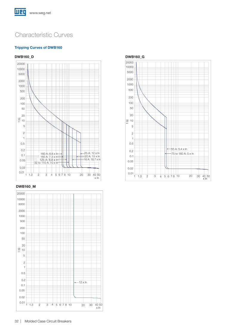
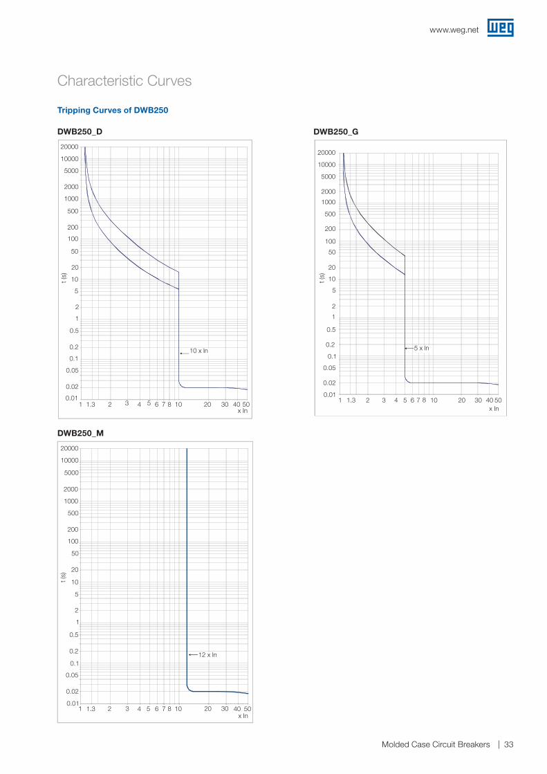
Tripping Curves of DWB160
DWB160_D
Characteristic Curves
160 A: 6.8 x ln
20000
10000
5000
2000
1000
500
200
100
50
20
10
5
2
1
0.5
0.2
0.1
0.05
0.02
0.011 1.3 2 3 4 5 6 7 8 10 20 30 40 50
x In
t (s)
25 A: 12 x ln20 A: 15 x ln
16 A: 18.7 x ln150 A: 7.3 x ln
125 A: 8.8 x ln32 to 110 A: 10 x ln
DWB160_G20000
10000
5000
2000
1000
500
200
100
50
20
10
5
2
1
0.5
0.2
0.1
0.05
0.02
0.011 1.3
75 to 160 A: 5 x ln
55 A: 5.4 x ln
2 3 4 5 6 7 8 10 20 30 40x In
50
t (s)
DWB160_M
20000
10000
5000
2000
1000
500
200
100
50
20
10
5
2
1
0.5
0.2
0.1
0.05
0.02
0.011.3 21 3 4 5 6 7 8 10 20 30 40
12 x ln
50x In
t (s)
www.weg.net
Molded Case Circuit Breakers 33
1 1,3 2 3 4 5 6 7 8 10 20 30 40 500,01
0,02
0,05
0,1
0,2
0,5
1
2
5
10
20
50
100
200
500
1000
2000
5000
10000
20000
t (s)
x In1 1,3 2 3 4 5 6 7 8 10 20 30 40 50
0,01
0,02
0,05
0,1
0,2
0,5
1
2
5
10
20
50
100
200
500
1000
2000
5000
10000
20000
t(s)
x In
10
20000
10000
5000
2000
1000
500
200
100
50
20
10
5
2
1
0.5
0.2
0.1
0.05
0.02
0.011 1.3 2 3 4 5 6 7 8 10 20 30 40 50
10 x ln
x In
t (s)
Tripping Curves of DWB250
DWB250_D
Characteristic Curves
DWB250_G
20000
10000
5000
2000
1000
500
200
100
50
20
10
5
2
1
0.5
0.2
0.1
0.05
0.02
0.011 1.3 2 3 4 5
5 x ln
6 7 8 10 20 30 40 50x In
t (s)
DWB250_M
1 1,3 2 3 4 5 6 7 8 10 20 30 40 500,01
0,02
0,05
0,1
0,2
0,5
1
2
5
10
20
50
100
200
500
1000
2000
5000
10000
20000
t(s)
x In
20000
10000
5000
2000
1000
500
200
100
50
20
10
5
2
1
0.5
0.2
0.1
0.05
0.02
0.011.3 21 3 4 5 6 7 8 10 20 30 40
12 x ln
50x In
t (s)
www.weg.net
Molded Case Circuit Breakers34
1 1,3 2 3 4 5 6 7 8 10 20 30 40 500,01
0,02
0,05
0,1
0,2
0,5
1
2
5
10
20
50
100
200
500
1000
2000
5000
10000
20000
t(s)
x In
1 1,3 2 3 4 5 6 7 8 10 20 30 40 500,01
0,02
0,05
0,1
0,2
0,5
1
2
5
10
20
50
100
200
500
1000
2000
5000
10000
20000
t(s)
x In
1 1,3 2 3 4 5 6 7 8 10 20 30 40 500,01
0,02
0,05
0,1
0,2
0,5
1
2
5
10
20
50
100
200
500
1000
2000
5000
10000
20000
t (s)
x In
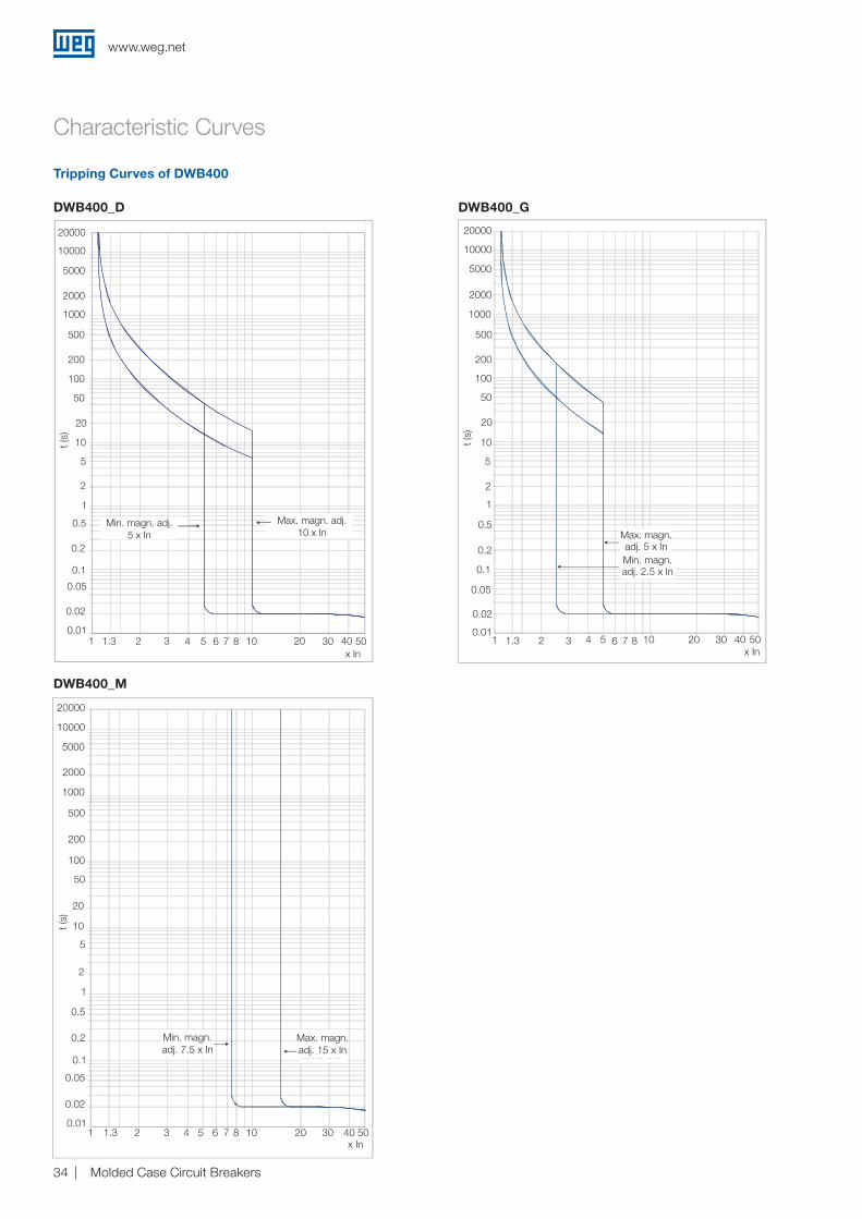
DWB400_G
Min. magn. adj.5 x In
Max. magn. adj.10 x In
20000
10000
5000
2000
1000
500
200
100
50
20
10
5
2
1
0.5
0.2
0.1
0.05
0.02
0.011 1.3 2 3 4 5 6 7 8 10 20 30 40 50
x In
t (s)
DWB400_M
Max. magn. adj. 15 x In
Min. magn. adj. 7.5 x In
20000
10000
5000
2000
1000
500
200
100
50
20
10
5
2
1
0.5
0.2
0.1
0.05
0.02
0.011.3 21 3 4 5 6 7 8 10 20 30 40 50
x In
t (s)
Tripping Curves of DWB400
DWB400_D
Characteristic Curves
Min. magn. adj. 2.5 x In
20000
10000
5000
2000
1000
500
200
100
50
20
10
5
2
1
0.5
0.2
0.1
0.05
0.02
0.011 1.3 2 3 4 5 6 7 8 10 20 30 40 50
x In
t (s)
Max. magn. adj. 5 x In
www.weg.net
Molded Case Circuit Breakers 35
1 1,3 2 3 4 5 6 7 8 10 20 30 40 500,01
0,02
0,05
0,1
0,2
0,5
1
2
5
10
20
50
100
200
500
1000
2000
5000
10000
20000
t(s)
x In
1 1,3 2 3 4 5 6 7 8 10 20 30 40 500,01
0,02
0,05
0,1
0,2
0,5
1
2
5
10
20
50
100
200
500
1000
2000
5000
10000
20000
t(s)
x In1 1,3 2 3 4 5 6 7 8 10 20 30 40 50
0,01
0,02
0,05
0,1
0,2
0,5
1
2
5
10
20
50
100
200
500
1000
2000
5000
10000
20000
t(s)
x In
.
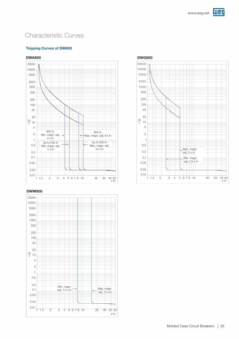
DWG800
Max. magn. adj. 5 x In
Min. magn.adj. 2.5 x In
20000
10000
5000
2000
1000
500
200
100
50
20
10
5
2
1
0.5
0.2
0.1
0.05
0.02
0.011 1.3 2 3 4 5 6 7 8 10 20 30 40 50
x In
t (s
)
800 A: Min. magn. adj.
4 x In
Up to 630 A: Min. magn. adj.
5 x In
800 A: Max. magn. adj. 8 x In
Up to 630 A: Max. magn. adj.
10 x In
20000
10000
5000
2000
1000
500
200
100
50
20
10
5
2
1
0.5
0.2
0.1
0.05
0.02
0.011 1.3 2 3 4 5 6 7 8 10 20 30 40 50
x In
t (s)
DWM800
Min. magn. adj. 7.5 x In Max. magn.
adj. 15 x In
20000
10000
5000
2000
1000
500
200
100
50
20
10
5
2
1
0.5
0.2
0.1
0.05
0.02
0.011.3 21 3 4 5 6 7 8 10 20 30 40 50
x In
t (s)
Tripping Curves of DW800
DWA800
Characteristic Curves
www.weg.net
Molded Case Circuit Breakers36
2084 62 12 15103 75 25 301 1.51.2
(rx In .m.s)
2...12xIn=Ii
t [s]
.001
.5
.002
.02
.05
.005
.01
10
5
2
1
.2
.1
10
2
2
5
3
(1min)
10
2
2
410
1
(1h)
x Ir (r.m.s)
5
5
4 62 103 75 12 2081,05
Ir = 0.4...1xIn
3
6
1218
tr = 1.6...18s at 6xIr
1.6
.1
.2
.3
.4
i²t ON
i²t OFF
Is = 2...10xIr
.1
.2
.3
.4
ts = 0.1...0.4s at 8xlr
Tole
ranc
e ±1
0%
1 1,3 2 3 4 5 6 7 8 10 20 30 40 500,01
0,02
0,05
0,1
0,2
0,5
1
2
5
10
20
50
100
200
500
1000
2000
5000
10000
20000
t(s)
x In
Characteristic Curves
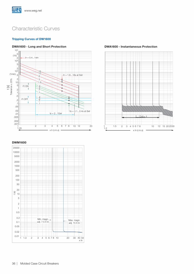
Tripping Curves of DW1600
DWA1600 - Long and Short Protection
DWM1600
Min. magn. adj. 7.5 X In
Max. magn. adj. 15 X In
20000
10000
5000
2000
1000
500
200
100
50
20
10
5
2
1
0.5
0.2
0.1
0.05
0.02
0.011.3 21 3 4 5 6 7 8 10 20 30 40 50
x In
t (s)
DWA1600 - Instantaneous Protection
t [s]
104
102
103
Ir = 0.4...1xIn
tr = 1.6...18s at 6xlr
ts = 0.1...0.4s at 8xlrIs = 2...10xlr
i2t OFF
i2t ON
(1min)
(1h)5
2
2
2
21
10
5
5
181263
.4
.4
.3
.3
.2
.2
.1
.1
1.65
.5
.05
.02
.01.005
1.05
.002
.001
.2.1
1 2 3 4 5 6 7 8 10 12 20
x Ir (r.m.s)
Tole
ranc
e ±
20%
2...12xIn= Ii
1.21.51 2 3 4 5 6 7 8 10 12 20 253015
x In (r.m.s)
www.weg.net
Molded Case Circuit Breakers 37
1 2 3 4 5 7 10 20 30 40 50 70 1001
2
3
4
5
7
10
20
30
40
50
70
100
200
Ip (k
Â)
Is (kA)1 2 3 4 5 7 10 20 30 40 50 70 100
1
2
3
4
5
7
10
20
30
40
50
70
100
200
Ip (k
Â)
Is (kA)
1 2 3 4 5 7 10 20 30 40 50 70 1001
2
3
4
5
7
10
20
30
40
50
70
100
200
Ip (kA
)
Is (kA)1 2 3 4 5 7 10 20 30 40 50 70 1001
2
3
4
5
7
10
20
30
40
50
70
100
200
N
BIp (kA
)
Is (kA)
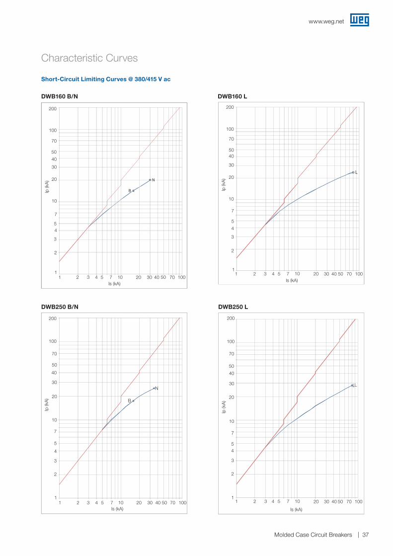
Short-Circuit Limiting Curves @ 380/415 V ac
DWB160 B/N
Characteristic Curves
DWB250 B/N DWB250 L
200
100
70
50
40
30
20
10
7
54
3
2
11 2
L
3 4 5 7 10
Is (kA)
Ip (k
A)
20 30 40 50 70 100
200
100
70
50
40
30
20
10
7
5
4
3
2
11 2
B
N
3 4 5 7 10Is (kA)
Ip (k
A)
20 30 40 50 70 100
DWB160 L
1 2 3 4 5 7 10Is (kA)
20 30 40 50 70 100
200
100
70
5040
30
20
10
7
5
4
3
2
1
Ip (k
A)
1 2 3 4 5 7 10Is (kA)
20 30 40 50 70 100
200
100
70
50
40
30
20
10
7
54
3
2
1
Ip (k
A)
www.weg.net
Molded Case Circuit Breakers38
1 2 3 4 5 7 10 20 30 40 50 70 1001
2
3
4
5
7
10
20
30
40
50
70
100
200
Ip (k
Â)
Is (kA)
1 2 3 4 5 7 10 20 30 40 50 70 1001
2
3
4
5
7
10
20
30
40
50
70
100
200
Ip (k
Â)
Is (kA)1 2 3 4 5 7 10 20 30 40 50 70 100
1
2
3
4
5
7
10
20
30
40
50
70
100
200
Ip (k
Â)
Is (kA)
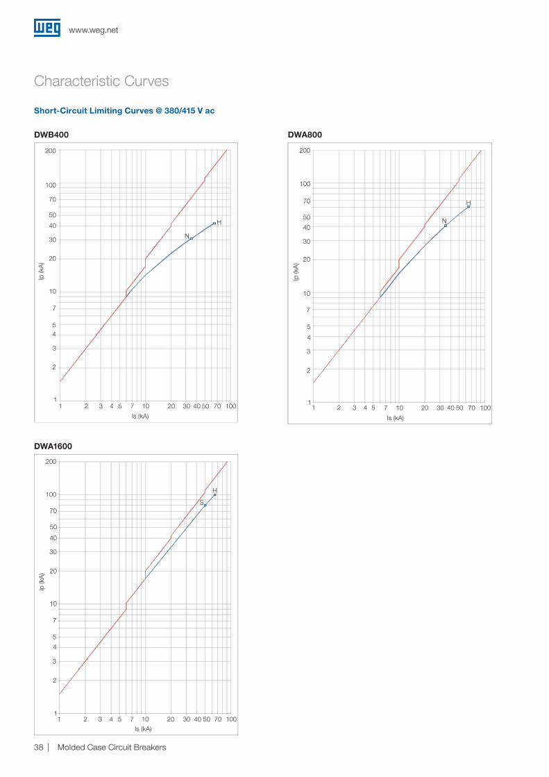
DWB400
200
100
70
50
40
30
20
10
7
N
H
54
3
2
11 2 3 4 5 77 1010
Ip (k
A)
Is (kA)2020 30 40404040 50 7070 100100
DWA1600
DWA800
Short-Circuit Limiting Curves @ 380/415 V ac
Characteristic Curves
200
100
70
50
40
30
20
10
7
S
H
5
4
3
2
11 2 3 4 5 7 10
Ip (k
A)
Is (kA)20 30 40 50 70 100
200
100
70
50
40
30
20
10
7
N
H
5
4
3
2
11 2 3 4 5 7 10
Is (kA)
Ip (k
A)
20 30 40 50 70 100
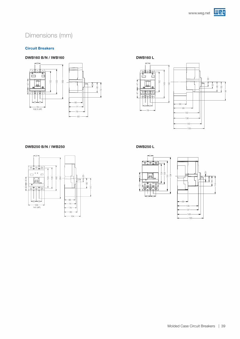
www.weg.net
Molded Case Circuit Breakers 39
Circuit Breakers
Dimensions (mm)
DWB160 B/N / IWB160
DWB250 B/N / IWB250
DWB160 L
DWB250 L
78
93
49
73
66
71
22
26
10
2
12
2
16
9
25 25
78
47
26
102.5 (4P)
93
78
71
6673
49
22
102
122
169
25 25
78
2647
26
47
47 10
2
14
3
24
25 25
78
19
2
33
49
52
66
99
132
136
143
159
22
94
49
24
159
143
136
132
99
66
94
5249
33
22
192
14310
2
2525
78
4747
45
43
135
12 4
35 35
105
37
264
162
83
104
23
65
66
74
78
117
37
141 (4P)
104
83
78
74
66
117
65
23
264
162
135
124
4543
3535
105
73
191
45
234
135
124
35 35
34
68
135
137
149
23
38
65
114
168
73
168
149
137
135
68
114
6538
23
134
19113
5
124
34
35 35
4573
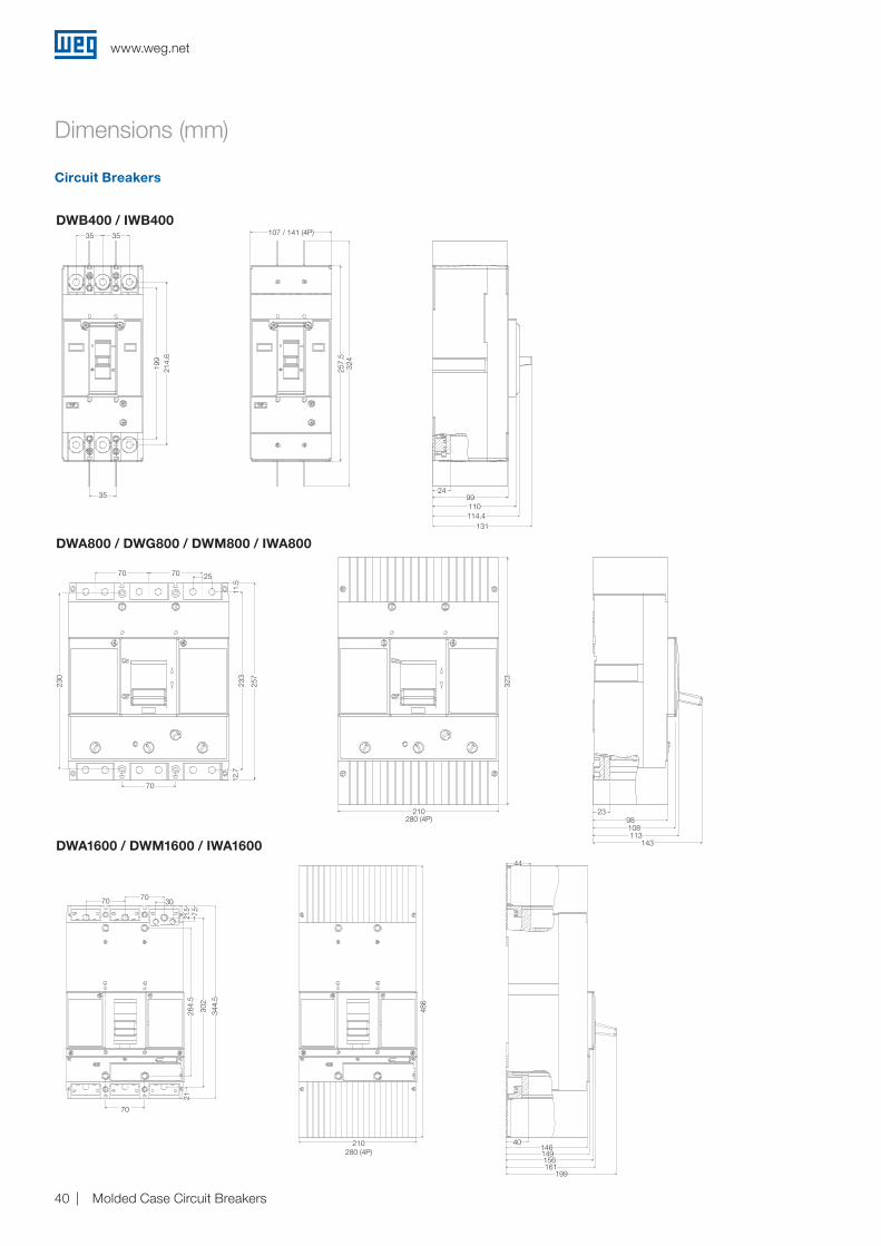
www.weg.net
Molded Case Circuit Breakers40
107
257
,5
324
99
114,4
131
24
35
35 35
199
214
,6
110
210
486
40
44
264
,5
302
21
DWB400 / IWB400
DWA800 / DWG800 / DWM800 / IWA800
Circuit Breakers
Dimensions (mm)
DWA1600 / DWM1600 / IWA1600
35 35
35
199
214.
6
107
257
,5
324
99
114,4
131
24
35
35 35
199
214
,6
110
107 / 141 (4P)
324
257.
5
107
257
,5
324
99
114,4
131
24
35
35 35
199
214
,6
110
131114.4110
9924
70
21
344.
5
7.5
21.5
302
7070 30
264.
5
210
486
40
44
264
,5
302
21
199161156149146
40
44
210
486
40
44
264
,5
302
21
210
486
280 (4P)
323
210
98
108
113
143
23
70
25
233
257
230
12,7
1
1,5
70 70
210280 (4P)
323
323
210
98
108
113
143
23
70
25
233
257
230
12,7
1
1,5
70 70
230
233
257
7070 25
11.5
70
12.7
323
210
98
108
113
143
23
70
25
233
257
230
12,7
1
1,5
70 70
143113
9823
108
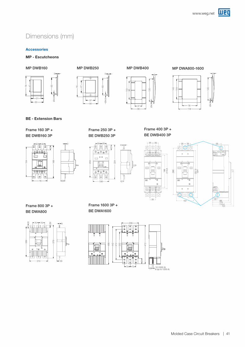
www.weg.net
Molded Case Circuit Breakers 41
Accessories
MP DWB160
Frame 160 3P +
BE DWB160 3P
MP DWB250
Frame 250 3P +
BE DWB250 3P
MP DWB400
Frame 400 3P +
BE DWB400 3P
MP DWA800-1600
Frame 800 3P +
BE DWA800
BE - Extension Bars
Frame 1600 3P +
BE DWA1600
Dimensions (mm)
257
,5
324
286
35 35
99
110
114,4
131
33
55
35
35 35
199
214
,6
107
35 35
107
55
131
110114.4
99
214.
6
286
324
257.
5
199
35 33
3535
MP - Escutcheons
76
50
47
31
3
4,6
63
5050
4776
50
31
Ø4.
663
376
56
47
37
3
4,6
63
3
47
Ø4.
6
376 47
Ø4.
656
3763
143
80
37
96
9
4,6
120
96143
120
8037 Ø
4.6
9
14
3
118
104
78
12
0
9
4,6
Ø4.
6
9
Ø4.
6
78
118
120
104
143
9
6
21
3535
22
4
31
106
20
3
21
6
224
203
106
35 35
31
22
330 30
78
16
8
15
4
23
30
22
3
168
154
30 30
23
78
29
8
210
70 70
29
379
339
20
210 29
379
339
82920 70 70
70 70
472
64
209
372
302
442
486
8 (up to 1250 A) 16 (1600 A)
39
486
442
372
302
472
209
70 70
64
39 16 (1600 A)8 (up to 1250 A)
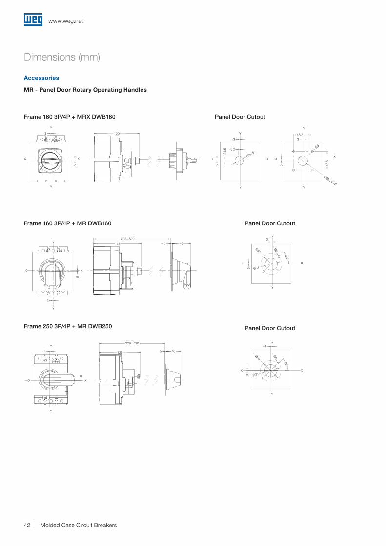
www.weg.net
Molded Case Circuit Breakers42
MR - Panel Door Rotary Operating Handles
Frame 160 3P/4P + MRX DWB160 Panel Door Cutout
Panel Door CutoutFrame 160 3P/4P + MR DWB160
Panel Door CutoutFrame 250 3P/4P + MR DWB250
Accessories
Dimensions (mm)
Y
Y
Y
XX
XX
Y
Y
XX
Y
Y
XX
Y
Y
XX
Y
Y
XX
Y
Y
Y
Y
X X
Y
Y
XX
X X
Y
Y
Y
XX
Y
Y
X
Y
X
Y
X
Y
X
Y
X X
Y
X X
Y
Y
XX
Y
MR DWA800
MRX DWB160
MR DWB250
MR DWA1600
MR DWB160
MRB DWB160
MR DWA400Furação da porta do Painel
Furação da porta do Painel
Furação da porta do Painel
Furação da porta do Painel
Furação da porta do Painel
Furação da porta do Painel
Furação da porta do Painel120
122
222...520
3627
2 0 5
305...580
5 46
156
256...580
5 46
129
229...520
5 46
122
222...520
5 46
180
280...550
5 46
3
5
3
5
0
8
5
3
0
4
2
46
2
81
5
3
45°
0
4
45°
2
81
45°
2
46
45°
0
8
45°
5
3
Ø22,5
24,5
3,2
5
3
Ø25... Ø
28
Ø5
48,5
48,5
5
3
45°
Ø53
Ø5
Ø 31
Ø53
Ø5
Ø 31
Ø 53Ø 5
Ø31
Ø 53Ø 5
Ø31
Ø 53Ø 5
Ø31
Ø40 Ø
4
Ø 21
Ø53
Y4
Ø31XX
Y
Y4
0
Ø53
Ø5
45°
Y
Y
Y
XX
XX
Y
Y
XX
Y
Y
XX
Y
Y
XX
Y
Y
XX
Y
Y
Y
Y
X X
Y
Y
XX
X X
Y
Y
Y
XX
Y
Y
X
Y
X
Y
X
Y
X
Y
X X
Y
X X
Y
Y
XX
Y
MR DWA800
MRX DWB160
MR DWB250
MR DWA1600
MR DWB160
MRB DWB160
MR DWA400Furação da porta do Painel
Furação da porta do Painel
Furação da porta do Painel
Furação da porta do Painel
Furação da porta do Painel
Furação da porta do Painel
Furação da porta do Painel120
122
222...520
3627
2 0 5
305...580
5 46
156
256...580
5 46
129
229...520
5 46
122
222...520
5 46
180
280...550
5 46
3
5
3
5
0
8
5
3
0
4
2
46
2
81
5
3
45°
0
4
45°
2
81
45°
2
46
45°
0
8
45°
5
3
Ø22,5
24,5
3,2
5
3
Ø25... Ø
28
Ø5
48,5
48,5
5
3
45°
Ø53
Ø5
Ø 31
Ø53
Ø5
Ø 31
Ø 53Ø 5
Ø31
Ø 53Ø 5
Ø31
Ø 53Ø 5
Ø31
Ø40 Ø
4
Ø 21
46
X
5
229...520
129
XX
0
Y
Y
4
Y
Y
Y
XX
XX
Y
Y
XX
Y
Y
XX
Y
Y
XX
Y
Y
XX
Y
Y
Y
Y
X X
Y
Y
XX
X X
Y
Y
Y
XX
Y
Y
X
Y
X
Y
X
Y
X
Y
X X
Y
X X
Y
Y
XX
Y
MR DWA800
MRX DWB160
MR DWB250
MR DWA1600
MR DWB160
MRB DWB160
MR DWA400Furação da porta do Painel
Furação da porta do Painel
Furação da porta do Painel
Furação da porta do Painel
Furação da porta do Painel
Furação da porta do Painel
Furação da porta do Painel120
122
222...520
3627
2 0 5
305...580
5 46
156
256...580
5 46
129
229...520
5 46
122
222...520
5 46
180
280...550
5 46
3
5
3
5
0
8
5
3
0
4
2
46
2
81
5
3
45°
0
4
45°
2
81
45°
2
46
45°
0
8
45°
5
3
Ø22,5
24,5
3,2
5
3
Ø25... Ø
28
Ø5
48,5
48,5
5
3
45°
Ø53
Ø5
Ø 31
Ø53
Ø5
Ø 31
Ø 53Ø 5
Ø31
Ø 53Ø 5
Ø31
Ø 53Ø 5
Ø31
Ø40 Ø
4
Ø 21
X
Y
Y Y
3
45°
Ø31
Ø5
XX
Ø535
Y
Y
Y
XX
XX
Y
Y
XX
Y
Y
XX
Y
Y
XX
Y
Y
XX
Y
Y
Y
Y
X X
Y
Y
XX
X X
Y
Y
Y
XX
Y
Y
X
Y
X
Y
X
Y
X
Y
X X
Y
X X
Y
Y
XX
Y
MR DWA800
MRX DWB160
MR DWB250
MR DWA1600
MR DWB160
MRB DWB160
MR DWA400Furação da porta do Painel
Furação da porta do Painel
Furação da porta do Painel
Furação da porta do Painel
Furação da porta do Painel
Furação da porta do Painel
Furação da porta do Painel120
122
222...520
3627
2 0 5
305...580
5 46
156
256...580
5 46
129
229...520
5 46
122
222...520
5 46
180
280...550
5 46
3
5
3
5
0
8
5
3
0
4
2
46
2
81
5
3
45°
0
4
45°
2
81
45°
2
46
45°
0
8
45°
5
3
Ø22,5
24,5
3,2
5
3
Ø25... Ø
28
Ø5
48,5
48,5
5
3
45°
Ø53
Ø5
Ø 31
Ø53
Ø5
Ø 31
Ø 53Ø 5
Ø31
Ø 53Ø 5
Ø31
Ø 53Ø 5
Ø31
Ø40 Ø
4
Ø 21
XX
5
X X
Y
Y
3 120
XX
Y
Ø22.5
3
3.2
24.5
Y
5
Y
48.53
Ø25...Ø28
48.5
Y
X
5
Ø5
Y
Y
Y
XX
XX
Y
Y
XX
Y
Y
XX
Y
Y
XX
Y
Y
XX
Y
Y
Y
Y
X X
Y
Y
XX
X X
Y
Y
Y
XX
Y
Y
X
Y
X
Y
X
Y
X
Y
X X
Y
X X
Y
Y
XX
Y
MR DWA800
MRX DWB160
MR DWB250
MR DWA1600
MR DWB160
MRB DWB160
MR DWA400Furação da porta do Painel
Furação da porta do Painel
Furação da porta do Painel
Furação da porta do Painel
Furação da porta do Painel
Furação da porta do Painel
Furação da porta do Painel120
122
222...520
3627
2 0 5
305...580
5 46
156
256...580
5 46
129
229...520
5 46
122
222...520
5 46
180
280...550
5 46
3
5
3
5
0
8
5
3
0
4
2
46
2
81
5
3
45°
0
4
45°
2
81
45°
2
46
45°
0
8
45°
5
3
Ø22,5
24,5
3,2
5
3
Ø25... Ø
28
Ø5
48,5
48,5
5
3
45°
Ø53
Ø5
Ø 31
Ø53
Ø5
Ø 31
Ø 53Ø 5
Ø31
Ø 53Ø 5
Ø31
Ø 53Ø 5
Ø31
Ø40 Ø
4
Ø 21
X
5
X X
Y
3
122
222...520
465
Y
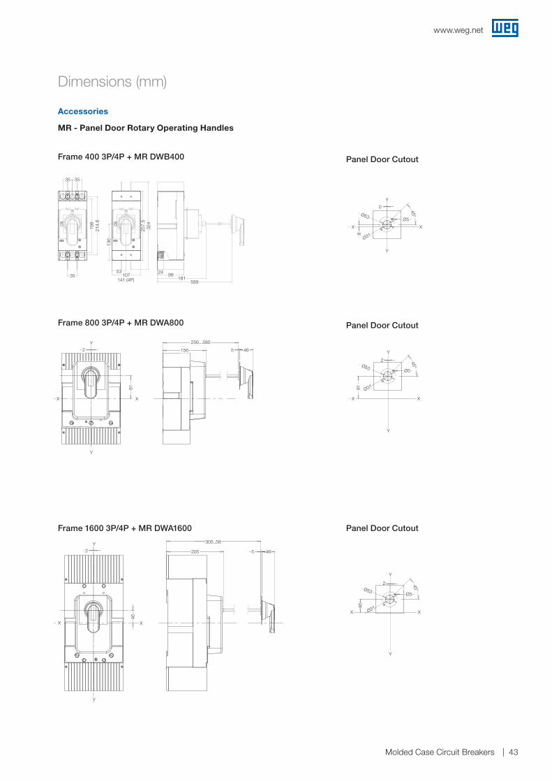
www.weg.net
Molded Case Circuit Breakers 43
Accessories
Dimensions (mm)
Frame 1600 3P/4P + MR DWA1600
Frame 800 3P/4P + MR DWA800
Panel Door Cutout
Panel Door Cutout
Panel Door Cutout
MR - Panel Door Rotary Operating Handles
Frame 400 3P/4P + MR DWB400
107
257
,5
324
53
136
35
35 35
199
214
,6
35
107141 (4P)
214.
6
324
257.
5
199
136
35
5399
24181
58935
Y
Y
Y
XX
XX
Y
Y
XX
Y
Y
XX
Y
Y
XX
Y
Y
XX
Y
Y
Y
Y
X X
Y
Y
XX
X X
Y
Y
Y
XX
Y
Y
X
Y
X
Y
X
Y
X
Y
X X
Y
X X
Y
Y
XX
Y
MR DWA800
MRX DWB160
MR DWB250
MR DWA1600
MR DWB160
MRB DWB160
MR DWA400Furação da porta do Painel
Furação da porta do Painel
Furação da porta do Painel
Furação da porta do Painel
Furação da porta do Painel
Furação da porta do Painel
Furação da porta do Painel120
122
222...520
3627
2 0 5
305...580
5 46
156
256...580
5 46
129
229...520
5 46
122
222...520
5 46
180
280...550
5 46
3
5
3
5
0
8
5
3
0
4
2
46
2
81
5
3
45°
0
4
45°
2
81
45°
2
46
45°
0
8
45°
5
3
Ø22,5
24,5
3,2
5
3
Ø25... Ø
28
Ø5
48,5
48,5
5
3
45°
Ø53
Ø5
Ø 31
Ø53
Ø5
Ø 31
Ø 53Ø 5
Ø31
Ø 53Ø 5
Ø31
Ø 53Ø 5
Ø31
Ø40 Ø
4
Ø 21
Y
Y
Y
XX
XX
Y
Y
XX
Y
Y
XX
Y
Y
XX
Y
Y
XX
Y
Y
Y
Y
X X
Y
Y
XX
X X
Y
Y
Y
XX
Y
Y
X
Y
X
Y
X
Y
X
Y
X X
Y
X X
Y
Y
XX
Y
MR DWA800
MRX DWB160
MR DWB250
MR DWA1600
MR DWB160
MRB DWB160
MR DWA400Furação da porta do Painel
Furação da porta do Painel
Furação da porta do Painel
Furação da porta do Painel
Furação da porta do Painel
Furação da porta do Painel
Furação da porta do Painel120
122
222...520
3627
2 0 5
305...580
5 46
156
256...580
5 46
129
229...520
5 46
122
222...520
5 46
180
280...550
5 46
3
5
3
5
0
8
5
3
0
4
2
46
2
81
5
3
45°
0
4
45°
2
81
45°
2
46
45°
0
8
45°
5
3
Ø22,5
24,5
3,2
5
3
Ø25... Ø
28
Ø5
48,5
48,5
5
3
45°
Ø53
Ø5
Ø 31
Ø53
Ø5
Ø 31
Ø 53Ø 5
Ø31
Ø 53Ø 5
Ø31
Ø 53Ø 5
Ø31
Ø40 Ø
4
Ø 21256...580
81
XX
2Y
Y
156 465
Y
Y
Y
XX
XX
Y
Y
XX
Y
Y
XX
Y
Y
XX
Y
Y
XX
Y
Y
Y
Y
X X
Y
Y
XX
X X
Y
Y
Y
XX
Y
Y
X
Y
X
Y
X
Y
X
Y
X X
Y
X X
Y
Y
XX
Y
MR DWA800
MRX DWB160
MR DWB250
MR DWA1600
MR DWB160
MRB DWB160
MR DWA400Furação da porta do Painel
Furação da porta do Painel
Furação da porta do Painel
Furação da porta do Painel
Furação da porta do Painel
Furação da porta do Painel
Furação da porta do Painel120
122
222...520
3627
2 0 5
305...580
5 46
156
256...580
5 46
129
229...520
5 46
122
222...520
5 46
180
280...550
5 46
3
5
3
5
0
8
5
3
0
4
2
46
2
81
5
3
45°
0
4
45°
2
81
45°
2
46
45°
0
8
45°
5
3
Ø22,5
24,5
3,2
5
3
Ø25... Ø
28
Ø5
48,5
48,5
5
3
45°
Ø53
Ø5
Ø 31
Ø53
Ø5
Ø 31
Ø 53Ø 5
Ø31
Ø 53Ø 5
Ø31
Ø 53Ø 5
Ø31
Ø40 Ø
4
Ø 21
Y
Y
Y
XX
XX
Y
Y
XX
Y
Y
XX
Y
Y
XX
Y
Y
XX
Y
Y
Y
Y
X X
Y
Y
XX
X X
Y
Y
Y
XX
Y
Y
X
Y
X
Y
X
Y
X
Y
X X
Y
X X
Y
Y
XX
Y
MR DWA800
MRX DWB160
MR DWB250
MR DWA1600
MR DWB160
MRB DWB160
MR DWA400Furação da porta do Painel
Furação da porta do Painel
Furação da porta do Painel
Furação da porta do Painel
Furação da porta do Painel
Furação da porta do Painel
Furação da porta do Painel120
122
222...520
3627
2 0 5
305...580
5 46
156
256...580
5 46
129
229...520
5 46
122
222...520
5 46
180
280...550
5 46
3
5
3
5
0
8
5
3
0
4
2
46
2
81
5
3
45°
0
445°
2
81
45°
2
46
45°
0
8
45°
5
3
Ø22,5
24,5
3,2
5
3
Ø25... Ø
28
Ø5
48,5
48,5
5
3
45°
Ø53
Ø5
Ø 31
Ø53
Ø5
Ø 31
Ø 53Ø 5
Ø31
Ø 53Ø 5
Ø31
Ø 53Ø 5
Ø31
Ø40 Ø
4
Ø 21
Y
Y
2Y
46
XX
305..58
205 465
Y
Y
Y
XX
XX
Y
Y
XX
Y
Y
XX
Y
Y
XX
Y
Y
XX
Y
Y
Y
Y
X X
Y
Y
XX
X X
Y
Y
Y
XX
Y
Y
X
Y
X
Y
X
Y
X
Y
X X
Y
X X
Y
Y
XX
Y
MR DWA800
MRX DWB160
MR DWB250
MR DWA1600
MR DWB160
MRB DWB160
MR DWA400Furação da porta do Painel
Furação da porta do Painel
Furação da porta do Painel
Furação da porta do Painel
Furação da porta do Painel
Furação da porta do Painel
Furação da porta do Painel120
122
222...520
3627
2 0 5
305...580
5 46
156
256...580
5 46
129
229...520
5 46
122
222...520
5 46
180
280...550
5 46
3
5
3
5
0
8
5
3
0
4
2
46
2
81
5
3
45°
0
4
45°
281
45°
2
46
45°
0
8
45°
5
3
Ø22,5
24,5
3,2
5
3
Ø25... Ø
28
Ø5
48,5
48,5
5
3
45°
Ø53
Ø5
Ø 31
Ø53
Ø5
Ø 31
Ø 53Ø 5
Ø31
Ø 53Ø 5
Ø31
Ø 53Ø 5
Ø31
Ø40 Ø
4
Ø 21
X
0
XX
Y
Y
Ø318
Ø5
45°Ø53
Y
Y
Y
XX
XX
Y
Y
XX
Y
Y
XX
Y
Y
XX
Y
Y
XX
Y
Y
Y
Y
X X
Y
Y
XX
X X
Y
Y
Y
XX
Y
Y
X
Y
X
Y
X
Y
X
Y
X X
Y
X X
Y
Y
XX
Y
MR DWA800
MRX DWB160
MR DWB250
MR DWA1600
MR DWB160
MRB DWB160
MR DWA400Furação da porta do Painel
Furação da porta do Painel
Furação da porta do Painel
Furação da porta do Painel
Furação da porta do Painel
Furação da porta do Painel
Furação da porta do Painel120
122
222...520
3627
2 0 5
305...580
5 46
156
256...580
5 46
129
229...520
5 46
122
222...520
5 46
180
280...550
5 46
3
5
3
5
0
8
5
3
0
4
2
46
2
81
5
3
45°
0
4
45°
281
45°
2
46
45°
0
8
45°
5
3
Ø22,5
24,5
3,2
5
3
Ø25... Ø
28
Ø5
48,5
48,5
5
3
45°
Ø53
Ø5
Ø 31
Ø53
Ø5
Ø 31
Ø 53Ø 5
Ø31
Ø 53Ø 5
Ø31
Ø 53Ø 5
Ø31
Ø40 Ø
4
Ø 21
Y
Ø53
81
X
Ø31
X
Y
Y
2
Ø5
45°
Y
Y
Y
XX
XX
Y
Y
XX
Y
Y
XX
Y
Y
XX
Y
Y
XX
Y
Y
Y
Y
X X
Y
Y
XX
X X
Y
Y
Y
XX
Y
Y
X
Y
X
Y
X
Y
X
Y
X X
Y
X X
Y
Y
XX
Y
MR DWA800
MRX DWB160
MR DWB250
MR DWA1600
MR DWB160
MRB DWB160
MR DWA400Furação da porta do Painel
Furação da porta do Painel
Furação da porta do Painel
Furação da porta do Painel
Furação da porta do Painel
Furação da porta do Painel
Furação da porta do Painel120
122
222...520
3627
2 0 5
305...580
5 46
156
256...580
5 46
129
229...520
5 46
122
222...520
5 46
180
280...550
5 46
3
5
3
5
0
8
5
3
0
4
2
46
2
81
5
3
45°
0
4
45°
2
81
45°
2
46
45°
0
8
45°
5
3
Ø22,5
24,5
3,2
5
3
Ø25... Ø
28
Ø5
48,5
48,5
5
3
45°
Ø53
Ø5
Ø 31
Ø53
Ø5
Ø 31
Ø 53Ø 5
Ø31
Ø 53Ø 5
Ø31
Ø 53Ø 5
Ø31
Ø40 Ø
4
Ø 21
XXX Ø3146
Ø53Ø5
45°
Y
Y
2
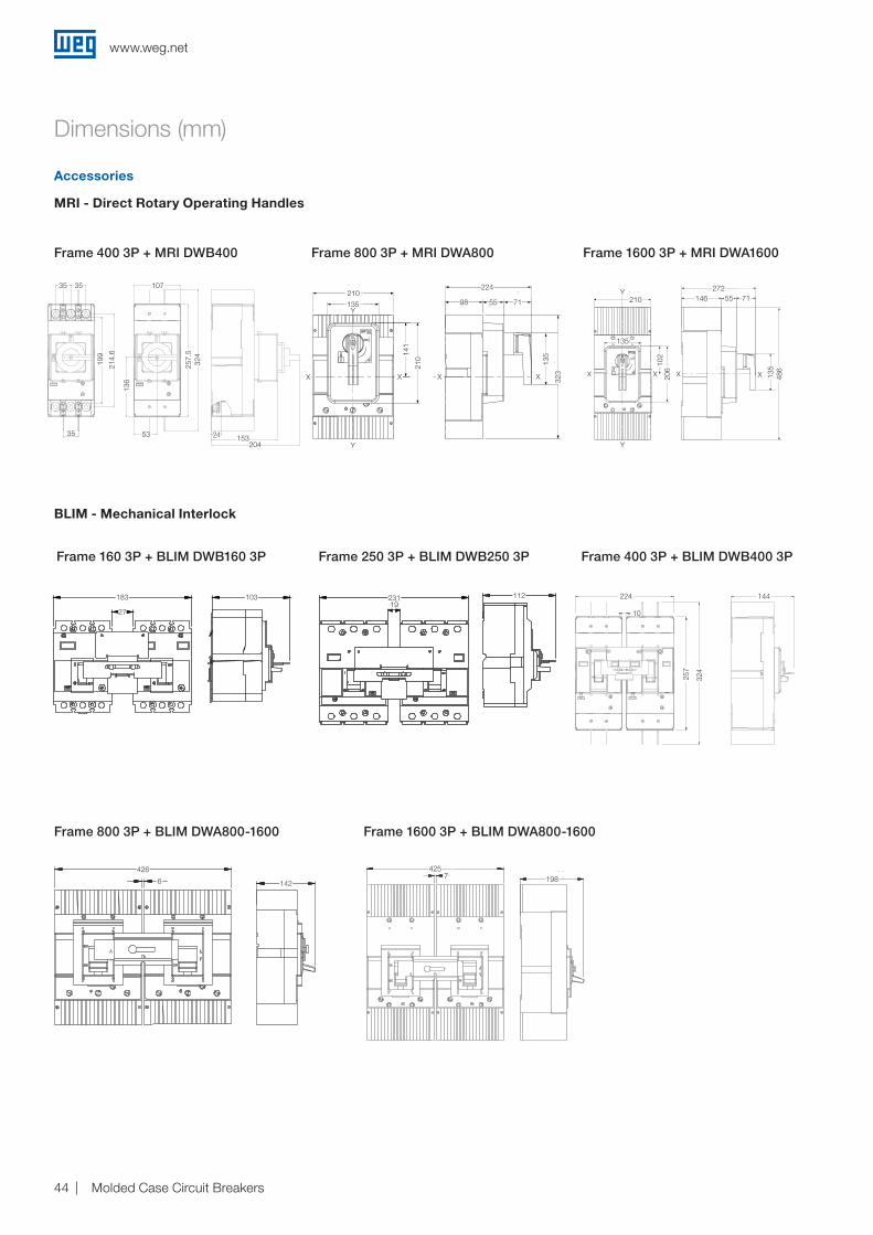
www.weg.net
Molded Case Circuit Breakers44
BLIM - Mechanical Interlock
Frame 160 3P + BLIM DWB160 3P Frame 250 3P + BLIM DWB250 3P
Frame 800 3P + BLIM DWA800-1600 Frame 1600 3P + BLIM DWA800-1600
Frame 400 3P + BLIM DWB400 3P
MRI - Direct Rotary Operating Handles
Frame 400 3P + MRI DWB400 Frame 800 3P + MRI DWA800 Frame 1600 3P + MRI DWA1600
Accessories
Dimensions (mm)
107
257
,5
324
53
136
24
153
204
35
35 35
199
214
,6
35
35 35 107
53204
15324
136
199
214.
6
257.
532
4
6
426
142142
426
6
19
231 1121122311927
183 103103183
27
146 55 71
135
486
272
102
210
206
135
Y
Y
XX X XXX
Y146 55 71
272
486
135
Y
102
206
X
210
135
X
98 55 71
13
5
32
3
224
14
1
210
135
21
0
Y
Y
X X X XX
X
323
135
98 55 71
224
XXX
Y
Y
141
210
X
135
210
E
D
C
B
A
1 2 3 4 5 6
Propriedade da WEG. Proibida reprodução sem autorização prévia./ WEG's property. Forbidden reproduction without previous authorization.
MASSA LÍQUIDA/NET WEIGHT
DATALIBERADOVERIFICADOEXECUTADO
DT LIBER/REL DT
LIBER/RELEASED
EXEC
VERIF/CHECKED
RODRIGOGL
RESUMO DE MODIFICAÇÕES
11
0018.08.2014
EXECUTEDVER
DATERELEASED
FOL/SHEET
LOCSUMMARY OF MODIFICATIONS
ECM
00
SWD -
A3
1:1ESCALA/SCALEMASSA BRUTA/GROSS WEIGHT
CHECKED
kg kg
10
224 144
257
324
10
224 144
257
324
7
425
198425
1987
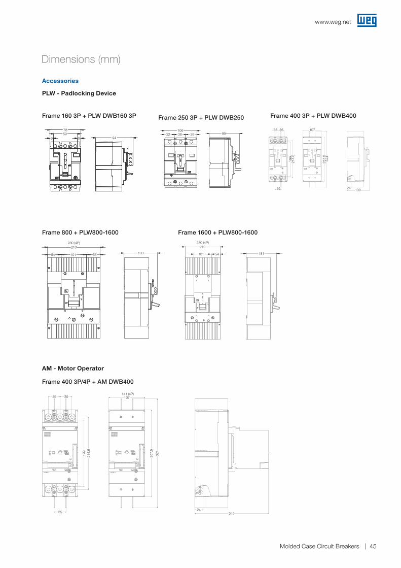
www.weg.net
Molded Case Circuit Breakers 45
Accessories
PLW - Padlocking Device
AM - Motor Operator
Frame 160 3P + PLW DWB160 3P Frame 250 3P + PLW DWB250 Frame 400 3P + PLW DWB400
Frame 800 + PLW800-1600 Frame 1600 + PLW800-1600
Dimensions (mm)
Frame 400 3P/4P + AM DWB400
107
257
,5
324
24
219 35
35 35
199
214
,6
35
214.
6
257.
5
324
21924
199
35 35 107141 (4P)
107
257
,5
324
24
130
35
35 35
199
214
,6
13024
107
199
214.
6
324
35
35 35
257.
5
94
59
9 9
78
94
7859
99
3832 35
10699
32 38 35106
99
55101
210
54133
54 101 55
210280 (4P)
133 54101
209
181101 54
210280 (4P)
181
www.weg.net
Molded Case Circuit breakers46
Industrial systems enhancing productivity.
Transforming energy into solutions. www.weg.net
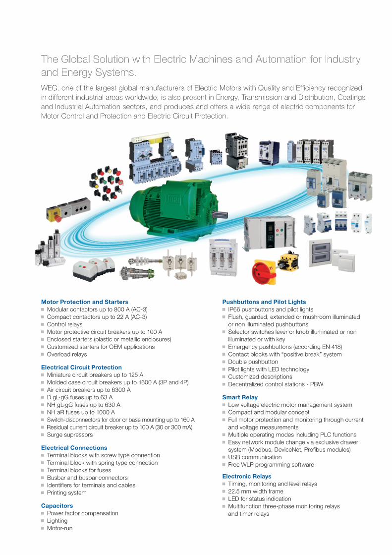
The Global Solution with Electric Machines and Automation for Industry and Energy Systems.WEG, one of the largest global manufacturers of Electric Motors with Quality and Efficiency recognized in different industrial areas worldwide, is also present in Energy, Transmission and Distribution, Coatings and Industrial Automation sectors, and produces and offers a wide range of electric components for Motor Control and Protection and Electric Circuit Protection.
Motor Protection and Starters g Modular contactors up to 800 A (AC-3) g Compact contactors up to 22 A (AC-3) g Control relays g Motor protective circuit breakers up to 100 A g Enclosed starters (plastic or metallic enclosures) g Customized starters for OEM applications g Overload relays
Electrical Circuit Protection g Miniature circuit breakers up to 125 A g Molded case circuit breakers up to 1600 A (3P and 4P) g Air circuit breakers up to 6300 A g D gL-gG fuses up to 63 A g NH gL-gG fuses up to 630 A g NH aR fuses up to 1000 A g Switch-disconnectors for door or base mounting up to 160 A g Residual current circuit breaker up to 100 A (30 or 300 mA) g Surge supressors
Electrical Connections g Terminal blocks with screw type connection g Terminal block with spring type connection g Terminal blocks for fuses g Busbar and busbar connectors g Identifiers for terminals and cables g Printing system
Capacitors g Power factor compensation g Lighting g Motor-run
Pushbuttons and Pilot Lights g IP66 pushbuttons and pilot lights g Flush, guarded, extended or mushroom illuminated or non illuminated pushbuttons
g Selector switches lever or knob illuminated or non illuminated or with key
g Emergency pushbuttons (according EN 418) g Contact blocks with “positive break” system g Double pushbutton g Pilot lights with LED technology g Customized descriptions g Decentralized control stations - PBW
Smart Relay g Low voltage electric motor management system g Compact and modular concept g Full motor protection and monitoring through current and voltage measurements
g Multiple operating modes including PLC functions g Easy network module change via exclusive drawer system (Modbus, DeviceNet, Profibus modules)
g USB communication g Free WLP programming software
Electronic Relays g Timing, monitoring and level relays g 22.5 mm width frame g LED for status indication g Multifunction three-phase monitoring relays and timer relays
Transforming energy into solutions. www.weg.net
Cod
: 50
0258
14 |
Rev
: 08
| Dat
e (m
/y):
12/2
014
The
valu
es s
how
n ar
e su
bje
ct to
cha
nge
with
out p
rior
notic
e.
WEG Worldwide Operations
WEG Group - Automation Business Unit Jaraguá do Sul - SC - Brazil Phone: +55 47 3276 4000 [email protected] www.weg.net
For those countries where there is not a WEG own operation, find our local distributor at www.weg.net.
ARGENTINAWEG EQUIPAMIENTOSELECTRICOSSan Francisco - CordobaPhone: +54 3564 421 [email protected]/ar
WEG PINTURAS - PulverluxBuenos AiresPhone: +54 11 4299 [email protected]
AUSTRALIAWEG AUSTRALIA Victoria Phone: +61 3 9765 [email protected]/au
AUSTRIAWATT DRIVE - WEG GroupMarkt PiestingPhone: +43 2633 404 [email protected]
BELGIUMWEG BENELUXNivelles - BelgiumPhone: +32 67 88 84 [email protected]/be
BRAZILWEG EQUIPAMENTOS ELÉTRICOSJaraguá do Sul - Santa CatarinaPhone: +55 47 [email protected]/br
CHILEWEG CHILE SantiagoPhone: +56 2 784 [email protected]/cl
CHINAWEG NANTONG Nantong - JiangsuPhone: +86 0513 8598 [email protected]/cn
COLOMBIAWEG COLOMBIA BogotáPhone: +57 1 416 [email protected]/co
ECUADORWEG ECUADOR QuitoPhone: 5144 339/342/[email protected]/ec
FRANCEWEG FRANCESaint Quentin Fallavier - LyonPhone: +33 4 74 99 11 [email protected]/fr
GERMANYWEG GERMANY KerpenPhone: +49 2237 9291 [email protected]/de
WEG BALINGEN BalingenPhone: +49 7433 9041 [email protected]
GHANAZEST ELECTRIC GHANA - WEG Group AccraPhone: +233 30 27 664 [email protected]
INDIAWEG ELECTRIC INDIABangalore - KarnatakaPhone: +91 80 4128 [email protected]/in
WEG INDUSTRIES INDIA Hosur - Tamil NaduPhone: +91 4344 301 [email protected]/in
ITALYWEG ITALIACinisello Balsamo - MilanoPhone: +39 02 6129 [email protected]/it
JAPANWEG ELECTRIC MOTORSJAPANYokohama City - KanagawaPhone: +81 45 550 [email protected]/jp
MALAYSIAWATT EURO-DRIVE - WEG GroupShah Alam - SelangorPhone: 603 [email protected]
MEXICOWEG MEXICOHuehuetocaPhone: +52 55 5321 [email protected]/mx
VOLTRAN - WEG GroupTizayuca - HidalgoPhone: +52 77 5350 9354www.voltran.com.mx
NETHERLANDSWEG NETHERLANDS - Oldenzaal - OverijsselPhone: +31 541 571 [email protected]/nl
PERUWEG PERU LimaPhone: +51 1 209 [email protected]/pe
PORTUGALWEG EUROMaia - PortoPhone: +351 22 [email protected]/pt
RUSSIA and CISWEG ELECTRIC CIS Saint PetersburgPhone: +7 812 363 [email protected]/ru
SOUTH AFRICAZEST ELECTRIC MOTORSWEG Group JohannesburgPhone: +27 11 723 [email protected]
SPAINWEG IBERIA MadridPhone: +34 91 655 30 [email protected]/es
SINGAPOREWATT EURO-DRIVE - WEG Group SingaporePhone: +65 6 862 [email protected]
WEG SINGAPORE SingaporePhone: +65 [email protected]/sg
SCANDINAVIAWEG SCANDINAVIA Kungsbacka - SwedenPhone: +46 300 73 [email protected]/se
UKWEG ELECTRIC MOTORS U.K.Redditch - WorcestershirePhone: +44 1527 513 [email protected]/uk
UNITED ARAB EMIRATESWEG MIDDLE EAST DubaiPhone: +971 4 813 [email protected]/ae
USAWEG ELECTRICDuluth - GeorgiaPhone: +1 678 249 [email protected] www.weg.net/us
ELECTRIC MACHINERY - WEG Group Minneapolis - MinnesotaPhone: +1 612 378 8000www.electricmachinery.com
VENEZUELAWEG INDUSTRIAS VENEZUELA Valencia - CaraboboPhone: +58 241 821 [email protected]/ve