sie datasheet margin a4 v4 - · pdf filecircuit breaker maintenance ... restricted by a 4...
TRANSCRIPT
Energy Management.
7SR158 Argus Voltage and Frequency Relay
Reyrolle
Protection
Devices

Siemens Protection Devices Limited 2
Siemens Protection Devices Limited 3
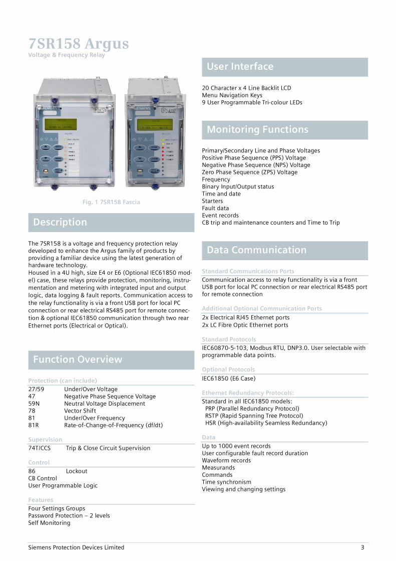
Fig. 1 7SR158 Fascia
The 7SR158 is a voltage and frequency protection relay developed to enhance the Argus family of products by providing a familiar device using the latest generation of hardware technology. Housed in a 4U high, size E4 or E6 (Optional IEC61850 mod-el) case, these relays provide protection, monitoring, instru-mentation and metering with integrated input and output logic, data logging & fault reports. Communication access to the relay functionality is via a front USB port for local PC connection or rear electrical RS485 port for remote connec-tion & optional IEC61850 communication through two rear Ethernet ports (Electrical or Optical).
Protection (can include) 27/59 Under/Over Voltage 47 Negative Phase Sequence Voltage 59N Neutral Voltage Displacement 78 Vector Shift 81 Under/Over Frequency 81R Rate-of-Change-of-Frequency (df/dt) Supervision 74T/CCS Trip & Close Circuit Supervision Control 86 Lockout CB Control User Programmable Logic Features Four Settings Groups Password Protection – 2 levels Self Monitoring
20 Character x 4 Line Backlit LCD Menu Navigation Keys 9 User Programmable Tri-colour LEDs
Primary/Secondary Line and Phase Voltages Positive Phase Sequence (PPS) Voltage Negative Phase Sequence (NPS) Voltage Zero Phase Sequence (ZPS) Voltage Frequency Binary Input/Output status Time and date Starters Fault data Event records CB trip and maintenance counters and Time to Trip
Standard Communications Ports Communication access to relay functionality is via a front USB port for local PC connection or rear electrical RS485 port for remote connection Additional Optional Communication Ports
2x Electrical RJ45 Ethernet ports 2x LC Fibre Optic Ethernet ports Standard Protocols IEC60870-5-103, Modbus RTU, DNP3.0. User selectable with programmable data points. Optional Protocols
IEC61850 (E6 Case) Ethernet Redundancy Protocols: Standard in all IEC61850 models: PRP (Parallel Redundancy Protocol) RSTP (Rapid Spanning Tree Protocol) HSR (High-availability Seamless Redundancy) Data Up to 1000 event records User configurable fault record duration Waveform records Measurands Commands Time synchronism Viewing and changing settings
7SR158 Argus Voltage & Frequency Relay
Data Communication
Monitoring Functions
User Interface
Function Overview
Description

Siemens Protection Devices Limited 4
FUN
CTIO
N
FUN
CTIO
NA
L RE
QU
IREM
ENT
7SR1
587-
5*A
**-*
CA0
7SR1
587-
5*A
**-*
DA
0
27 Undervoltage ■ ■47 Negative Phase Sequence Voltage ■ ■59 Overvoltage ■ ■
59N Neutral Voltage Displacement ■ ■
78 Vector Shift ■
81 Under/Over Frequency ■ ■
81R Rate of Change of Frequency ■
CONTROL / MONITOR
74T/CCS Trip & Close Circuit Supervision ■ ■86 Lockout ■ ■
74TCCS(x3)
3 47(x2)
59N(x2)
27/59
(x4)
81R(x6)
81(x6)
78(x2)
CT/VT CONFIG > Phase Voltage Config:Van,Vbn,Vcn, or Vab,Vbc,3V0
74TCCS(x3)
3 47(x2)
59N(x2)
27/59
(x4)
81R(x6)
81(x6)
CT/VT CONFIG > Phase Voltage Config:Va,Vb,Vc
* *
*
* Not all versions - see Function Matrix
Fig. 2 Functional Diagrams
B17
B19
B21
B23
B25
B27
Va
Vb
Vc
A B C
B17
B19
B21
B23
B25
B27
Va
Vb
Vc
Dn
Da
B17
B19
B21
B23
B25
B27
Va
Vb
Vc
CT/VT CONFIG >Phase Voltage Config:Van,Vbn,Vcn
CT/VT CONFIG >Phase Voltage Config:Va,Vb,Vc
CT/VT CONFIG >Phase Voltage Config:Vab,Vbc,3V0
Fig. 3 VT Connections
VT Connections Function Matrix

Siemens Protection Devices Limited 5
With reference to figure 2 ‘Function Diagrams’. 27/59 Under/Over Voltage Each element has settings for pickup level, drop-off level and Definite Time Lag (DTL) delay. Operates when voltage exceeds setting for the duration of delay. 47 Negative Phase Sequence Voltage Each element has settings for pickup level and Definite Time Lag (DTL) delays. Operates when NPS voltage exceeds setting for the duration of delay. 59N Neutral Overvoltage Neutral overvoltage can be used to detect earth faults in high impedance earthed or isolated systems. Operates when neutral voltage exceeds setting for the duration of delay. 74T/CCS Trip & Close Circuit Supervision The trip or close circuit(s) can be monitored via binary inputs. Detection of trip circuit failure can be used to raise an HMI alarm (general alarm) and/or output(s). 78 Vector Shift Operates if the voltage vector ‘jumps’ by more than setting during abrupt change in load. The function is applied to detect ‘islanding’ or loss of connection between a generator and the main utility supply. 81 Under/Overfrequency Each element has settings for pickup level, drop-off level and Definite Time Lag (DTL) delays. Operates if frequency ex-ceeds setting for duration of delay. The function is typically applied in load shedding schemes. 81R Rate of Change of Frequency (df/dt) Each element has settings for pickup level and Definite Time Lag (DTL) delay. Operates when the df/dt gradient exceeds setting for duration of delay. The function is typically applied in load shedding schemes or to detect ‘islanding’ or loss of connection between a genera-tor and the main utility supply Programmable Logic The user can map binary inputs, protection elements, LEDs and binary outputs together in a logical scheme. Up to 4 logic equations can be defined using standard logic functions e.g. Timers, AND/OR gates, Inverters and Counters to provide the user required functionality. Each logic equation output can be used for alarm & indication and/or tripping. Virtual Inputs/Outputs There are 8 virtual inputs/outputs to provide internal logical states to assist in the application of the functions. Each virtual I/O can be assigned in the same way as a physical I/O. Circuit Breaker Maintenance Two circuit breaker operations counters are provided to assist with maintenance scheduling. The maintenance counter records the overall number of operations and the
delta counter records the number of operations since the last reset. Each counter has a user set target operations count which, when reached, can be mapped to raise alarms/ binary outputs. A CB Trip Time meter is also available, which measures the time between the trip or open command being issued and the auxiliary contacts changing state. Control Mode The relay has a control menu with access to commonly used command operations. Access to the control commands is restricted by a 4 character control function password. Each command requires a select then execute operation, if the execute operation is not performed within a time window the command is aborted. The following control functions are available:
CB Control Local or remote operation
Fig.4 Example of Control Function View
Description of Functionality
Siemens Protection Devices Limited 6
Sequence of event records Up to 1000 events are stored and time tagged to 1ms resolution. Fault Records The last 10 fault records are displayed on the relay fascia and are also available through the communication interface, with time and date of trip, measured quantities and type of fault. Waveform recorder The waveform recorder stores analogue data for all poles and the states of protection functions, binary inputs, LEDs and binary outputs with user settable pre & post trigger data. A record can be triggered from protection function, binary input or via data communications. 10 seconds of waveform storage are available, configurable as 10 records of 1 second duration, 5 of 2 seconds, 2 of 5 seconds or 1 record of 10 seconds duration. Demand Metering A rolling record of demand over the last 24h is stored. The demand is averaged over a user selectable period of time. A rolling record of such demand averages is stored and provides the demand history. A typical application is to record 15min averages for the last 7 days. Real Time Clock The time and date can be set and are maintained while the relay is de-energised by a back up storage capacitor. The time can be synchronized from a binary input pulse or the data communication channel.
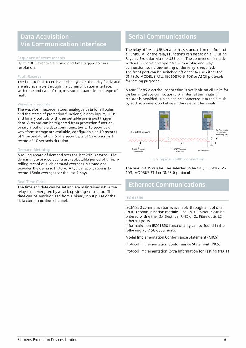
The relay offers a USB serial port as standard on the front of all units. All of the relays functions can be set on a PC using Reydisp Evolution via the USB port. The connection is made with a USB cable and operates with a ‘plug and play’ connection, so no pre-setting of the relay is required. The front port can be switched off or set to use either the DNP3.0, MODBUS-RTU, IEC60870-5-103 or ASCII protocols for testing purposes. A rear RS485 electrical connection is available on all units for system interface connections. An internal terminating resistor is provided, which can be connected into the circuit by adding a wire loop between the relevant terminals.
To Control System
14161820
RS485 Screened twisted pair Rear terminals
141618
RS485 Screened twisted pair
Ext Wire loop to Include line
terminating Res
Fig.5 Typical RS485 connection The rear RS485 can be user selected to be OFF, IEC60870-5-103, MODBUS RTU or DNP3.0 protocol.
IEC 61850 IEC61850 communication is available through an optional EN100 communication module. The EN100 Module can be ordered with either 2x Electrical RJ45 or 2x Fibre optic LC Ethernet ports. Information on IEC61850 functionality can be found in the following 7SR158 documents:
Model Implementation Conformance Statement (MICS)
Protocol Implementation Conformance Statement (PICS)
Protocol Implementation Extra Information for Testing (PIXIT)
Ethernet Communications
Serial Communications Data Acquisition - Via Communication Interface

Siemens Protection Devices Limited 7
Fig.6 Typical Reydisp Evolution Screenshot
Reydisp Evolution is common to the entire range of Reyrolle numeric products. The user can apply settings, interrogate settings, retrieve events and fault data. Language Editor The Language editor software gives the user the ability to customize the text displayed in the relay menu structure and instrumentation. The tool allows a language file to be created and transferred to the relay also containing Western European characters.
Fig.7 Typical Language Editor Screenshot
Communications Editor To facilitate interfacing to a substation the relay default Protocol configuration may be modified using the communication editor software tool. The communication editor is a PC based software package provided within the Reydisp software suite which allows modification of the IEC60870-5-103, DNP 3.0 and MODBUS Protocols.
Fig.8 Typical Communications Editor Screenshot
Reydisp Manager provides the functionality of Reydisp Evolution and also provides project management of multiple devices to allow engineering of IEC61850 projects. It also provides access to user logic within the devices via an easy to use graphical interface.
Reydisp Manager
Reydisp Evolution

Siemens Protection Devices Limited 8
The relay is housed in a 4U high size E4 or E6 case with a removable clear plastic fascia cover. The plastic fascia cover can be ordered with or without two push buttons to allow the user to view the settings and instruments without removing the cover. Two plastic handles are provided to allow the relay to be withdrawn from its case, contacts in the case ensure that the normally closed contacts remain short circuited when the relay is withdrawn. The rear terminal blocks comprise M4 female terminals for ring crimp wire connections, to provide a secure and reliable termination.
Fig.9 Rear view of relay (E4 Case)
Fig.10 Rear view of relay with 2x LC Fibre Optic ports (E6 Case with IEC61850)
Fig.11 User Interface
The operator interface is designed to provide a user friendly method of controlling, viewing menus, entering settings and retrieving data from the relay. Five buttons are provided for navigation around the menu structure. LCD A 4 line by 20 character liquid crystal display with power save operation indicates the relay identifier, settings, instrumentation, fault data and control commands. Up to 6 user programmable general alarms can be configured to display your own indications on the LCD. LEDs A green steadily illuminated LED indicates the ‘Protection Healthy’ condition. 9 user programmable LEDs are available eliminating the need for expensive panel mounted pilot lights and associated wiring. Each LED is tri-color (red, green, yellow) allowing for clear indication of the associated function’s state and has a label insert for identification. Relay Information The device is identified by the rating label on the fascia. The user can give the device its own unique identity by editing the ‘Relay Identifier’ displayed on the LCD, also space is provided for a further slip-in label.
User Interface Construction

Siemens Protection Devices Limited 9
For full technical data refer to the Performance Specification Section of the Technical Manual.
Voltage Inputs
Nominal 40…160 Vrms Operating Range 0… 200 Vrms Instrumentation ≥ 0.8xVn ±1% Vn Burden @ 110V ≤ 0.06 VA Overvoltage Withstand 300 Vrms
Auxiliary Supply
Rated DC Voltage 110/125/220/250V
Range 64 to 300V 24/48/60V Range 18 to 72V
Allowable superimposed ac component
12% of DC voltage
Rated AC Voltage 115 VAC 50/60Hz Range 92 to 138 V rms AC 50/60Hz ±5%
Power Consumption:
E4 Min (DC) E4 Max (DC)
3.9W 8W
E4 Min (AC) E4 Max (AC)
9VA 0.5PF 16VA 0.5PF
E6 Min (DC) E6 Max (DC)
6.4W 10.5W
E6 Min (AC) E6 Max (AC)
14.5VA 0.5PF 21.5VA 0.5PF
Allowable breaks/dips in supply (collapse to zero)
DC 50ms AC 2.5/3 cycles
@50/60Hz Binary Inputs
Number 6
Operating Voltage 19V dc DC Range 17 to 320V dc AC Range 92 to 138 VRMSAC
88V dc Range 70 to 320V dc
Maximum dc current for operation
1.5mA
Maximum peak ac current for operation
1.5mA
Pick Up Delay User Selectable 0 to 14,400,000ms (up to 4 hours)
Drop Off Delay User Selectable 0 to 14,400,000ms (up to 4 hours)
For AC operation the BI pick-up delay should be set to 0ms and the drop-off delay to 20ms.
Binary Outputs
Number 8
(3 change over contacts) Operating Voltage Voltage Free Operating Mode User selectable - Self or
Hand/Electrical Reset or pulsed. Operating Time from Energizing Binary Input
<20ms
Making Capacity: Carry continuously Make and carry (L/R ≤ 40 ms and V ≤ 300 V)
5A ac or dc 20A ac or dc for 0.5s 30A ac or dc for 0.2s
Breaking Capacity ( ≤ 5 A and ≤ 300 V): AC Resistive AC Inductive DC Resistive DC Inductive
1250 VA 250 VA at p.f. ≤ 0.4 75 W 30 W at L/R ≤ 40ms 50 W at L/R ≤ 10ms
Housing E4 or E6 (see dimension
drawing) Indication 20 Character 4 line Display
Relay Healthy LED 9 Tri Coloured User Programmable Self or Hand Reset LED’s
With-drawable Element Yes User Interface 5 Navigation Keys Weight Typical 2.7kg E4 case,
3.65 kg E6 case. Additional Transport packaging: add 0.4kg
IP Rating installed with cover
IP 51 from front
IP Rating installed without cover
IP 20 from front
Unit Design
Inputs and Outputs
Technical Data

Siemens Protection Devices Limited 10
Communication Port Front USB Type B
Rear RS485 2 wire electrical
IEC61850 optional ports: 2x Electrical RJ45 Ethernet 2x LC Fibre Optic Ethernet
Protocols IEC60870-5-103
MODBUS RTU (Serial)
DNP3.0 O (Serial)
IEC61850 - optional
Fibre Optic Ethernet Data Communication Interface (IEC 61850 Option)
EN100 Fibre Optic Data Communication Interface (IEC 61850 Option) Physical
layer Fibre-optic
Connectors Duplex LC 100BaseF in acc. With IEEE802.3
Recommended fibre 62.5/125 µm glass fibre with Duplex-LC connector
Transmission Speed 100 MBits/s
Optical Wavelength 1300 nm
Bridgeable distance 2 km
EN100 Electrical Ethernet Data Communication Interface (IEC 61850 Option) Physical
Electrical
Connectors RJ45 100BaseT in acc. With IEEE802.3
Transmission Speed 100 MBits/s
Test Voltage (with regard to socket)
500 VAC 50 Hz
Bridgeable distance 20m
Fault Record 10 Waveform Record 10 x 1sec
2 x 5sec 5 x 2sec 1 x 10sec Pre trigger 10…90%
Events 1000 1ms Resolution
Vibration (Sinusoidal)
IEC 60255-21-1 Class I Type Level Variation Vibration response 0.5 gn ≤ 5 % Vibration response 1.0 gn ≤ 5 %
Shock and Bump
IEC 60255-21-2 Class I Type Level Variation Shock response 5 gn, 11 ms ≤ 5 % Shock withstand 15 gn, 11 ms ≤ 5 % Bump test 10 gn, 16 ms ≤ 5 %
Seismic
IEC 60255-21-3 Class I Type Level Variation
Seismic response
X-plane - 3.5mm displacement below crossover freq (8-9Hz) 1gn and above Y-plane – 1.5mm displacement below crossover freq (8-9Hz) 0.5gn above
≤ 5 %
Mechanical Classification
Durability >106 operations
Mechanical Tests
Data Storage
Data Communication Interface

Siemens Protection Devices Limited 11
Insulation
IEC 60255-5 Type Level
Between any terminal and earth
2.0 kV AC RMS for 1 min
Between independent circuits
2.0 kV AC RMS for 1 min
Across normally open contacts
1.0 kV AC RMS for 1 min
High Frequency Disturbance
IEC 60255-22-1 Class III Type Level Variation Common (longitudinal) mode
2.5 kV ≤ 5 %
Series (transverse) mode
1.0 kV ≤ 5 %
Electrostatic Discharge
IEC 60255-22-2 Class IV Type Level Variation Contact discharge 8.0 kV ≤ 5 %
Fast Transients
IEC 60255-22-4 Class A (2002) Type Level Variation 5/50 ns 2.5 kHz repetitive
4kV ≤ 5 %
Surge Immunity
IEC 60255-22-5 Type Level Variation
Analog Inputs:
Line to Earth 4.0 kV ≤ 10%
Case, Aux Power & I/O: Line to Earth
2.0 kV ≤ 10%
RS485 Comms port: Line to Earth
1.0 kV No Data Loss
Analog Inputs:
Line to Line 1.0 kV ≤ 10%
Case, Aux Power & I/O: Line to Line
1.0 kV * ≤ 10%
* Note 50ms DTL pick-up delay applied to binary inputs
Conducted Radio Frequency Interference
IEC 60255-22-6 Type Level Variation 0.15 to 80 MHz 10 V ≤ 5 %
Radiated Radio Frequency
IEC 60255-25 Type Limits at 10 m, Quasi-peak 30 to 230 MHz 40 dB(µV) 230 to 10000 MHz 47 dB(µV)
Conducted Radio Frequency
Type Limits
Quasi-peak Average 0.15 to 0.5 MHz 79 dB(µV) 66 dB(µV) 0.5 to 30 MHz 73 dB(µV) 60 dB(µV)
Radiated Immunity IEC 60255-22-3 Class III Type Level 80 MHz to 1000 MHz Sweep 10 V/m
1.4GHz to 2.7GHz Sweep 10V/m
80,160,380,450,900,1850,2150 MHz Spot
10V/m
Temperature
IEC 60068-2-1/2 Operating Range -10°C to +55°C Storage range -25°C to +70°C
Humidity
IEC 60068-2-78 Operational test 56 days at 40°C and 93% relative
humidity IP Ratings IEC 60529 Type Level
Installed with cover IP 51 from front of relay
Installed with cover removed IP 20 from front of relay
Environmental Tests
Electrical Tests

Siemens Protection Devices Limited 12
27/59 Under/Over Voltage
Number of Elements 4 Under or Over Operate Any phase or All phases Under-Voltage Guard 1,1.5…200V Setting Range Vs 5,5.5…200V Hysteresis Setting 0.0.1…80% Vs Operate Level 100% Vs, ±1% or ±0.25V Reset Level: Overvoltage Undervoltage
= (100% - hyst) x Vop, ±1% = (100% + hyst) x Vop, ±1%
Delay Setting td 0.00,0.01…20,20.5…100,101…1000,1010…10000,10100…14400s
Basic Operate Time : 0 to 1.1xVs 0 to 2.0xVs 1.1 to 0.5xVs
73ms ±10ms 63ms ±10ms 58ms ±10ms
Operate time following delay.
Tbasic +td , ±1% or ±10ms
Inhibited by Binary or Virtual Input Voltage Guard
47 Negative Phase Sequence Voltage
Number of Elements 2 Under-Voltage Guard 1,1.5…200V Setting Range Vs 1,1.5…90V Hysteresis Setting 0.0.1…80% Operate Level 100% Vs, ±2% or ±0.5V Reset Level (100% - hyst) x Vop, ±1%
or ± 0.25V Delay Setting td 0.00,0.01…20,20.5…100,101…
1000,1010…10000,10100…14400s
Basic Operate Time : 0 to 2.0 x Vs 0 to 10 x Vs
80ms ±20ms 70ms ±20ms
Operate time following delay.
Tbasic + td , ±2% or ±20ms
Inhibited by Binary or Virtual Input Voltage Guard
74T/CC Trip/Close Circuit Supervision
Number of supervisable circuits
3 x Trip and 3 x Close
Number of BI’s Required 1 or 2 per function 78 Vector Shift
Number of Elements 2 Under-Voltage Guard 1,1.5…200V Setting Range VSs 2.0, 2.5 ... 30 °
Operate Level 100% VSs, ± 2°
Operate Time ≤ 40ms
81 Under/Over Frequency
Number of Elements 6 Under or Over Under Voltage Guard 35,35.5…200V Setting Range 43,43.01…68Hz Hysteresis Setting 0, 0.1… 2% Operate Level 100% Fs ±10mHz Operate Time Maximum <150ms Operate Delay 0…14400s
81R Rate of Change of Frequency (df/dt)
Number of Elements 6 Under Voltage Guard 35,35.5…200V Setting Range Rs 0.050, 0.075 …10.0 Hz/s Operate Level Rs ± 50mHz/s (F.nom ± 3Hz) Operate Time for ROCOF 1.3x setting for ROCOF 2x setting
≤ 300ms ≤ 200ms
Operate Delay 0…200s 59N Neutral Voltage Displacement
Number of Elements DT & IT DT Setting Range Is 1…100V DT Operate Level 100% Vs, ±2% or ±0.5V DT Delay Setting td 0 …14400s DT Basic Operate Time 0V to 1.5 x Vs 0V to 10 x Vs
76ms ±20ms 63ms ±20ms
DT Operate time following delay.
Tbasic +td , ±1% or ±20ms
IT Char Setting IDMTL & DTL IT Setting Range 1…100V Tm Time Multiplier(IDMT)
0.1…140
Delay (DTL) 0…20s Reset ANSI Decaying, 0…60s Char Operate Level 100% Vs, ±2% or ±0.5V Inhibited by Binary or Virtual Input
Control Functions
CB Open/Close
CB Maintenance
Trip Counter Total & Delta
0…10000 Counts to AR Block 0…10000 Frequent Operations 0…10000 I2t Alarm 10…100000
Performance
Siemens Protection Devices Limited 13
E4PANEL CUT-
OUT168
78
98.5
159
10
SIDE VIEW
31 216.5
25mm MIN CLEARANCE FOR TERMINAL WIRING
FRONT VIEW
103.5
177
151.
5
11Case Earthconnection
Typical when fitted
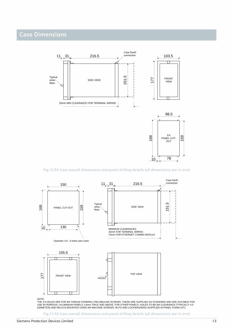
Fig.12 E4 Case overall dimensions and panel drilling details (all dimensions are in mm)
TOP VIEW
FRONT
NOTE:THE 3.6 HOLES ARE FOR M4 THREAD FORMING (TRILOBULAR) SCREWS. THESE ARE SUPPLIED AS STANDARD AND ARE SUITABLE FOR USE IN FERROUS / ALUMINIUM PANELS 1.6mm THICK AND ABOVE. FOR OTHER PANELS, HOLES TO BE M4 CLEARANCE (TYPICALLY 4.5 DIAMETER) AND RELAYS MOUNTED USING M4 MACHINE SCREWS, NUTS AND LOCKWASHERS (SUPPLIED IN PANEL FIXING KIT).
PANEL CUT-OUT168
130
150
159
10
Diameter 3.6 - 4 holes (see note)
FRONT VIEW
155.5
177
SIDE VIEW
31 216.511Case Earthconnection
Typical when fitted
MINIMUM CLEARANCES:25mm FOR TERMINAL WIRING75mm FOR ETHERNET COMMS MODULE
151.
5
Fig.13 E6 Case overall dimensions and panel drilling details (all dimensions are in mm)
Case Dimensions
Siemens Protection Devices Limited 14
EthernetData
Comms(optional)
AB
1 2
27 28
1 2
27 28
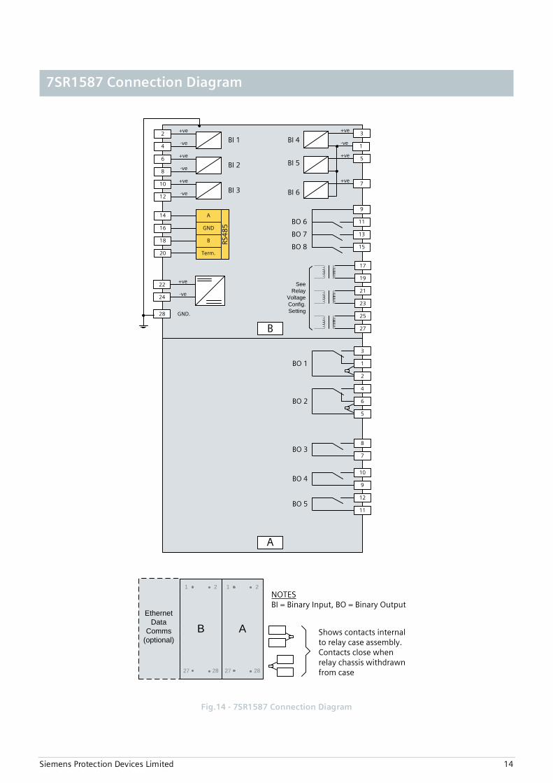
Shows contacts internal to relay case assembly.Contacts close when relay chassis withdrawn from case
NOTESBI = Binary Input, BO = Binary Output
BO 1
GND.
BI 1
A
RS4
85GND
B
Term.
+ve
-ve
+ve
-ve
22
24
28
2
4
BI 2+ve
-ve
6
8
BI 3+ve
-ve
10
12
14
16
18
20
BI 4+ve 3
BI 5+ve 5
BI 6
+ve
-ve
7
1
BO 2 6
5
4
1
2
3
BO 38
7
BO 7
11
13
BO 8 15
9
BO 410
9
BO 512
11
A
BO 6
17
19
21
23
25
27B
SeeRelay
VoltageConfig.Setting
Fig.14 - 7SR1587 Connection Diagram
7SR1587 Connection Diagram

Siemens Protection Devices Limited 15
Product description Variants Order No.
Voltage/frequency relay 7 S R 1 5 8 7 - 5 □ A □ □ - □ □ A 0 ▲ ▲ ▲ ▲ ▲ ▲ ▲ ▲ ▲ ▲ ▲ ▲
| | | | | | | | | | | | Protect Product Family | | | | | | | | | | | | Voltage 5 | | | | | | | | | | | | | | | | | | | | | | Relay Type | | | | | | | | | | | Voltage & Frequency 8 | | | | | | | | | | | | | | | | | | | | Case, I/O and Fascia | | | | | | | | | | E4 case, 3 VT, 6 Binary Inputs / 8 Binary Outputs, 10 LEDs 7 | | | | | | | | | | | | | | | | | | Measuring input | | | | | | | | | 40 to 160 V, 50/60Hz 5 | | | | | | | | | | | | | | | | Auxiliary voltage
80 to 250 V DC / 115 V AC, binary input threshold 19 V DC 80 to 250 V DC binary input threshold 88 V DC
| G H
| | |
| | |
| | |
| | |
| | |
| | |
| | |
24 to 60 V DC, binary input threshold 19 V DC J | | | | | | |
Spare
| | A
| | |
| | |
| | |
| | |
| | |
| | |
Communication Interface Standard version – included in all models, USB front port, RS485 rear port (E6 Case) 1) Standard version - plus additional rear electrical Ethernet RJ45 (x2) (E6 Case) 1) Standard version - plus additional rear optical Ethernet duplex (x2) (E6 Case) 1) Protocol
| 1 7 8
| 2 7 7 | |
| | | | | |
| | | | | |
| | | | | |
| | | | | |
IEC 60870-5-103, Modbus RTU and DNP3(user selectable setting) 2 | | | | IEC 60870-5-103, Modbus RTU, DNP3 and IEC 61850. (user selectable settings) 7 | | | | | | | | Front Cover | | | | Standard Version – No Push Buttons 1 | | | Push Buttons – Down and right Arrows 2 | | | | | | Protection Function Packages | | | For future development A | | For future development B | | Standard Version C | | 27/59 Under/overvoltage | | | 47 Negative phase sequence voltage | | | 59N Neutral voltage displacement | | | 74T&C Trip & Close circuit supervision | | | 81 Under/overfrequency | | | | | | Standard version – plus D | | 78 Voltage Vector Shift | | 81R Rate of Change of Frequency
Additional Functionality No additional functionality
| | | A
| | | | |
Spare 0
1) E4 case is standard, E6 case is required if IEC61850 option fitted
Ordering Information – 7SR1587

Siemens Protection Devices Limited 16
Published by and copyright © 2016: Siemens Protection Devices Limited
P.O. Box 8
North Farm Road
Hebburn
Tyne & Wear
NE31 1TZ
United Kingdom
Phone: +44 (0)191 401 7901
Fax: +44 (0)191 401 5575
E-mail: [email protected]
EMEA-C10033-00-76GB
September 2016
For enquires please contact our Customer Support Center
Phone: +49 180/524 8437 (24hrs)
Fax: +49 180/524 24 71
E-mail: [email protected]
www.siemens.com/protection
Subject to change without notice,. Printed in the UK.
www. siemens.com/energy