siddharth group of institutions :: puttur ...sietk.org/downloads/question bank/ii b.tech i...
TRANSCRIPT

QUESTION BANK 2017
Strength of Materials-I 1
SIDDHARTH GROUP OF INSTITUTIONS :: PUTTUR
Siddharth Nagar, Narayanavanam Road – 517583
QUESTION BANK (DESCRIPTIVE)
Subject with Code : Strength of Materials-I (16CE103) Course & Branch: B.Tech - CE
Year & Sem: II-B.Tech & I-Sem Regulation: R16
UNIT –I
SIMPLE STRESSES AND STRAINS & STRAIN ENERGY
1. a) A rod 150 cm long and of diameter 2.0 cm is subjected to an axial pull of 20 kN. If the
modulus of elasticity of the material of the rod is 2x10⁵ N/ mm2 ; determine : the Stress, Strain
and Elongation of the rod. [6M]
b) Define Poisson’s ratio and Factor of safety. [4M]
2. a) Fid the Young’s Modulus of a brass rod of diameter 25 mm ad of length 300 mm subjected
to a tensile load of 60 kN when the extension of the rod is equal to 0.2 m. [7M]
b) Write the classification of stresses. [3M]
3. The following data refer to a mild steel specimen tested in a laboratory:
(i) Diameter of the specimen = 25 mm
(ii) Length of specimen = 300 mm
(iii) Extension under a load of 15 kN = 0.045 mm
(iv) Load at yield point = 127.65 kN
(v) Maximum load = 208.6 kN
(vi) Length of specimen after failure = 375 mm
(vii) Neck diameter = 17.75 mm
Determine (a) Young’s modulus (b) Yield stress (c) Ultimate stress (d) Percentage of
elongation (e) Percentage in reduction area. [2M+2M+2M+2M+2M]
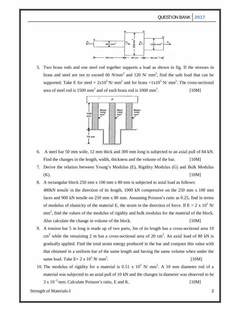
4. A member ABCD is subjected to point loads P1, P2 , P3 and P4 as shown in figure. Calculate the
force P2 necessary for equilibrium, if P1=45 kN, P3 =450 kN and P4=130kN. Determine the total
elongation of the member, assuming the modulus of elasticity to be 2.1 x 10⁵ N/ mm2 [10M]
QUESTION BANK 2017
Strength of Materials-I 2
5. Two brass rods and one steel rod together supports a load as shown in fig. If the stresses in
brass and steel are not to exceed 60 N/mm2 and 120 N/ mm2, find the safe load that can be
supported. Take E for steel = 2x10⁵ N/ mm2 and for brass =1x10⁵ N/ mm2. The cross-sectional
area of steel rod is 1500 mm2 and of each brass rod is 1000 mm2. [10M]
6. A steel bar 50 mm wide, 12 mm thick and 300 mm long is subjected to an axial pull of 84 kN.
Find the changes in the length, width, thickness and the volume of the bar. [10M]
7. Derive the relation between Young’s Modulus (E), Rigidity Modulus (G) and Bulk Modulus
(K). [10M]
8. A rectangular block 250 mm x 100 mm x 80 mm is subjected to axial load as follows:
480kN tensile in the direction of its length, 1000 kN compressive on the 250 mm x 100 mm
faces and 900 kN tensile on 250 mm x 80 mm. Assuming Poisson’s ratio as 0.25, find in terms
of modulus of elasticity of the material E, the strain in the direction of force. If E = 2 x 10⁵ N/
mm2, find the values of the modulus of rigidity and bulk modulus for the material of the block.
Also calculate the change in volume of the block. [10M]
9. A tension bar 5 m long is made up of two parts, 3m of its length has a cross-sectional area 10
cm2 while the remaining 2 m has a cross-sectional area of 20 cm2. An axial load of 80 kN is
gradually applied. Find the total strain energy produced in the bar and compare this value with
that obtained in a uniform bar of the same length and having the same volume when under the
same load. Take E= 2 x 10⁵ N/ mm2. [10M]
10. The modulus of rigidity for a material is 0.51 x 10⁵ N/ mm2. A 10 mm diameter rod of a
material was subjected to an axial pull of 10 kN and the changes in diameter was observed to be
3 x 10 -3 mm. Calculate Poisson’s ratio, E and K. [10M]

QUESTION BANK 2017
Strength of Materials-I 3
UNIT –II
SHEAR FORCE AND BENDING MOMENT 1. Draw shear force and bending moment diagram for cantilever beam subjected to uniformly
distributed load. [10M]
2. Draw the shear force and bending moment diagram for the cantilever beam shown in figure.
[10M]
3. Draw shear forc and bending moment diagram for the following beam [10M]
4. Draw shear forc and bending moment diagram for the following beam [10M]
5. A cantilever beam AB of span 10 m carries a uniformly distributed load of 50 kN /m on span 5
m from support B. A point load of 30 kN at the mid span. Draw shear force and bending
moment diagrams. [10M]
6. Draw shear force and bending moment diagram for the following beam [10M]
7. Draw shear force and bending moment diagram for the overhanging loaded as show in fig. And
also locate the point of contra-flexure. [10M]

QUESTION BANK 2017
Strength of Materials-I 4
8. Draw the shearing force and bending moment diagrams for the beam shown in figure. [10M]
9. Draw the SFD and BMD for simply supported beam carrying uniformly distributed load of
whole length and also derive equation for it. [10M]
10. Draw shear force and bending moment diagram for the following beam [10M]

QUESTION BANK 2017
Strength of Materials-I 5
UNIT –III
THEORY OF SIMPLE BENDING AND SHEAR STRESS DISTRIBUTION 1. Derive the bending equation M/I = f/y = E/R Writing all the assumptions made. [10M]
2. A cast Iron beam is of T- section has the following dimensions Flange: 100 mm x 20 mm Web:
80 mm x 20 mm. The beam is simply supported on a span of 8 meters and carries a uniformly
distributed load of 1.5 KN/m length of entire span. Determine the maximum tensile and
compressive stresses. [10M]
3. A rolled steel joist of I section has a dimensions as shown in fig. This beam of I section carries a
uniformly distributed load of 40 kN /m run on a span of 10 m, calculate the maximum stress
produced due to bending. [10M]
4. A beam is simply supported and carries a uniformly distributed load of 40KN/m run over the
whole span. The section of the beam is rectangular having depth as 500mm. If the maximum
stress in the material of the beam is 120 N/mm2 and moment of inertia of the section is 7 x 10 8
mm4, find the span of the beam. [10M]
5. An I-section has the following dimensions
Flanges: 150 mm x 20 mm Web: 310 mm x 10 mm. If the shear force acting on the section is
40 KN. Calculate the maximum shear stress developed in I-section and stress distribution
diagram. [10M]
6. A simply supported wooden beam of span 1.3 m having a cross section 150 mm wide and 250
mm deep carries a point load W at the center. The permissible shear stress is 7 N/mm2 in
bending and 1 N/mm2 in shearing. Calculate the safe load W. [10M]
7. A rectangular beam 100 mm wide and 250 mm deep is subjected to a maximum shear force of
50 KN. Determine i) Average shear stress ii) Maximum shear stress iii) Shear stress at a distance
of 25 mm above neutral axis. [10M]
8. An I-section has 100 mm wide and 12 mm thickness, a web of 120 mm height and 10 mm
thickness. The section is subjected to bending moment of 15 KN-m and shear force of 10 KN.
QUESTION BANK 2017
Strength of Materials-I 6
Find the maximum bending stress and maximum shear stress and draw shear stress distribution
diagram. [10M]
9. A simply supported beam carries a uniformly distributed load of intensity 30 N/mm over the
entire span of 2 m. The cross section of beam is a T-section having flange 125 x 25 mm and web
175 x 25 mm. Calculate the maximum shear stress for the section subjected to maximum shear
force. Also draw the shear stress distribution. [10M]
10. The shear force acting on a beam at a section is ‘F’. The section of the beam is triangular base b
and of an altitude h. The beam is placed with its base horizontal. Find the maximum shear stress
and the shear stress at the neutral axis. [10M]
UNIT –IV
DEFLECTIONS OF BEAMS 1. Derive the expression for slope and deflection of a simply supported beam carrying a point load
at centre using double integration method. [10M] 2. A beam of length 6 m is simply supported at its ends and carries a point load of 40 kN at a
distance of 4 m from the left support. Find the deflection under the load and maximum
deflection. Also calculate the point at which maximum deflection takes place. Given moment of
inertia of beam is 7.33 x 10⁷ N/mm2 and E = 2 x 10⁵ N/mm2. Use Macaulay’s method. [10M] 3. A beam 6 m long, simply supported at its ends, is carrying a point load of 50 kN at its center.
The moment of inertia of the beam is given as equal to 78 x 106 mm4 and. If E for the material of
the beam = 2.1 x 10⁵ N/mm2, calculate: (i) deflection at the centre of the beam and (ii) slope at
the supports. [10M] 4. A beam of uniform rectangular section 200 mm wide and 300 deep is simply support at its ends.
It carries a uniformly distributed load of 9 kN/m run over the entire span of 5 m. If the value of
E for the beam material is 1 x 10⁴ N/mm2, find : (i) Slope at the supports and (ii) Maximum deflection. [10M]
5. Derive the expression for slope and deflection of a simply supported beam carrying a uniformly
distributed load by Mohr’s theorem. [10M] 6. A cantilever of length 3m carries a uniformly distributed load over the entire length. If the
deflection at the free end is 40 mm, find the slope at the free end. [10M] 7. Derive the expression for slope and deflection of a cantilever beam carrying a point load at the
free end by Moment Area method. [10M]

QUESTION BANK 2017
Strength of Materials-I 7
8. Derive the expression for slope and deflection of a simply supported beam carrying a uniformly
distributed load of w per unit length over the entire length using double integration method.
[10M] 9. A beam of length 5 m of uniform rectangular section is supported at its ends and carries a
uniformly distributed load over the entire length. Calculate the depth of the section if the
maximum permissible bending stress is 8 N/mm2 and central deflection not to exceed 10 mm.
Take E = 1.2 X 10⁴ N/ mm2. [10M] 10. A simply supported beam carries a UDL of 20 kN/m over its span of 8 m. Determine the slope at
the ends and the deflection at mid span by moment area method if E = 200 G N/m2 and I=
30,000 cm4. [10M]
UNIT –V
CONJUGATE BEAM METHOD AND TORSION OF CIRCULAR SHAFTS AND
SPRINGS 1. Derive the expression for slope and deflection of a simply supported beam with a point load at
the center by Conjugate beam method. [10M]
2. A cantilever beam of length 3m carries a uniformly distributed load of 80 kN/m over the entire
length. If E= 2 x 10⁸ kN/m2 and I=1 x 108 mm4, find the slope and deflection at the free end
using conjugate beam method. [10M]
3. A Simply supported beam of length 5 m carries a point load of 5 kN at a distance of 3 m from
left end. If E = 2 x 10⁵ N/mm2 and Ι = 1 × 108 mm4 for the beam, determine: (i) slope at left
support and (ii) deflection under the point load using conjugate beam method. [10M]
4. A cantilever beam of length 3 m carries a point load of 10 kN at a distance of 2 m from the fixed
end. If E=2 x 10⁵ N/mm2 and I = 1 x 108 mm4, find the slope and deflection at the free end using
conjugate bean method. [10M]
5. A tensile test, a test piece 25 mm in diameter, 200 mm gauge length stretched 0.0975 mm under
a pull of 50,000 N. In a torsion test the same rod twisted 0.025 rad over a length of 200 mm,
when a torque of 400 Nmm was applied. Evaluate the Poisson’s ratio and the three elastic
moduli for the material. [10M]
6. A solid shaft of 200 mm diameter has the same cross sectional area as that of a hollow shaft of
the same material with inside diameter of 150 mm. Find the ratio of the power transmitted by the
hollow shaft by the same speed. [10M]

QUESTION BANK 2017
Strength of Materials-I 8
7. A hollow shaft of external diameter 120 mm transmits 300 kW power at 200 r.p.m. (rotations per
minute) Determine the maximum internal diameter if the maximum stress in the shaft is not
exceeded to 60 N/mm2. [10M]
8. A hollow shaft is to transmit 300kW power at 80 rpm. If the shear stress is not exceed 60 N/mm2
and the internal diameter is 0.6 of the external diameter. Find the external and internal diameters
assuming that the maximum torque is 1.4 times the mean. [10M]
9. A solid circular shaft transmits 75 kW power at 200 rpm. Calculate the shaft diameter, if the
twist in the shaft is not to exceed 10 in 2 m length of shaft, and shear stress is limited to 50
N/mm2. Take C= 1 x 10⁵ N/mm2. [10M]
10. A closely coil helical spring of round steel wire 10 mm in diameter having 10 complete turns
with a mean diameter of 12 cm is subjected to an axial load of 200 N. Determine :
(i) Deflection of the beam spring (ii) Maximum shear stress in the wire and (iii) Stiffness
of the spring. Take C= 8x10⁴ N/mm2. [10M]
Prepared by: M. MUZAFFAR AHMED
V.S.MEGANATHAN