pisal siddharth
DESCRIPTION
wimax physicalTRANSCRIPT

PHYSICAL LAYER COMPARATIVE STUDY OF WiMAX AND LTE
_______________
A Thesis
Presented to the
Faculty of
San Diego State University
_______________
In Partial Fulfillment
of the Requirements for the Degree
Master of Science
in
Electrical Engineering
_______________
by
Siddharth Shrikant Pisal
Spring 2012


iii
Copyright © 2012
by
Siddharth Shrikant Pisal
All Rights Reserved

iv
DEDICATION
To all my family, professors and friends
v
ABSTRACT OF THE THESIS
Physical Layer Comparative Study of WiMAX and LTEby
Siddharth Shrikant PisalMaster of Science in Electrical Engineering
San Diego State University, 2012
The world of technology has given mankind a powerful way for interaction usingtelecommunication. When invented by Alexander Graham Bell, it was a wired transmissionof electrical signals representing information. Since then, telecommunication technology hasachieved tremendous improvement from text, voice transmission to a modern age high speedreal time multimedia content. The challenges for today’s technology is to develop standardsthat can help operators to keep the cost per bit as low as possible and keep on reducing,maintain backward compatibility so as to gain maximum benefit from the investments. Thenewer modulation schemes and improved advanced antenna technologies are helping toachieve the newer heights of success. The technology so far has developed through 1st, 2ndand 3rd generation phases and currently 4G (4th Generation) is the best experience till datefor users.
In March 2008, the International Telecommunications Union-Radio communicationssector (ITU-R) specified a set of requirements for 4G standards, named the IMT-Advanced(International Mobile Telecommunications Advanced) specification, setting peak speedrequirements at 100 megabits per second (Mbit/s) for high mobility communication (such asfrom trains and cars) and 1 gigabit per second (Gbit/s) for low mobility communication. Tomeet IMT-Advanced requirements, IEEE 802.16m (Mobile WiMAX) an IEEE standard andLong Term Evolution (LTE) from 3GPP groups are considered and both satisfy the IMT-Advanced requirements.
4G goals are challenging compared to 3G standards. To achieve the 4G requirements,two standards were candidates. IEEE developed Mobile WiMAX, a successor of IEEE802.16 (2009) standard for Local and metropolitan area networks. Mobile WiMAXsupersedes the IMT-Advanced requirements using OFDMA modulation and advancedMIMO antenna technology. Long Term Evolution (LTE), a 3GPP technology developed tomeet the IMT-Advanced requirements uses OFDMA modulation scheme for Downlink andSC-FDMA for Uplink to improve PAPR and save battery power on mobile user devices.LTE also uses advanced MIMO antenna technology to increase the data rates and supersedesthe IMT-Advanced requirements.
This thesis investigates physical layers of LTE and WiMAX designed for improveddata rates, system capacity, and robustness. Both technologies use variable bandwidth andflexible adaptive modulation techniques with efficient physical resource allocation to utilizethe available channel and achieve the best possible throughput. Best utilization of Time andfrequency resources is the key for best performance results. Physical layer parameters forWiMAX and LTE use physical resources in different ways and achieve optimizedperformance under real time scenarios. Various aspects of physical layer results and

vi
parameters are analyzed for understanding the similarities and differences amongst thetechnologies.

vii
TABLE OF CONTENTS
PAGE
ABSTRACT...............................................................................................................................v
LIST OF TABLES................................................................................................................... xi
LIST OF FIGURES ................................................................................................................ xii
CHAPTER
1 MODULATION TECHNIQUES AND SYNCHRONIZATION SIGNALSFOR LTE AND WIMAX ..............................................................................................1
1.1 Introduction........................................................................................................1
1.2 Orthogonal Frequency Division Modulation (OFDM)......................................2
1.2.1 Working Principle of OFDM....................................................................3
1.2.1.1 OFDM Transmitter ..........................................................................3
1.2.1.2 OFDM Receiver...............................................................................5
1.2.2 OFDMA in LTE and WiMAX..................................................................5
1.3 OFDM Technique Drawbacks ...........................................................................7
1.3.1 PAPR Issue with OFDM Techniques .......................................................7
1.3.2 PAPR Reduction Techniques....................................................................8
1.4 Single Carrier Orthogonal Frequency Division Multiple Access ......................8
1.4.1 SC-FDMA Transmitter Structure .............................................................9
1.4.1.1 Localized Transmission ...................................................................9
1.4.1.2 Distributed Transmission.................................................................9
1.4.2 SC-FDMA Receiver Structure................................................................10
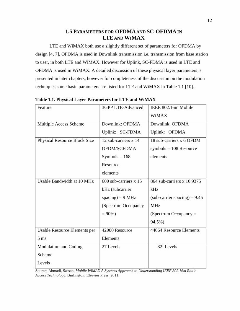
1.5 Parameters for OFDMA and SC-OFDMA in LTE and WiMAX....................12
1.6 Synchronization Signal used in LTE and WiMAX .........................................13
1.7 Zadoff-Chu Sequences.....................................................................................13
1.8 ZC Sequences in LTE and WiMAX ................................................................14
1.8.1 ZC Sequence in LTE...............................................................................15
1.8.2 ZC Sequences in WiMAX ......................................................................16
2 STUDY OF LONG TERM EVOLUTION (LTE).......................................................17

viii
2.1 Introduction......................................................................................................17
2.2 LTE Physical Layer General Description ........................................................18
2.3 Physical Layer Frame Structure.......................................................................19
2.4 Concept of Resource Block .............................................................................19
2.4.1 LTE Resource Block...............................................................................19
2.4.2 LTE and WiMAX Subcarrier Spacing....................................................19
2.5 Duplexing Modes in LTE ................................................................................20
2.6 TDD Frame Structure in LTE ..........................................................................21
2.7 Special Subframes in TDD ..............................................................................21
2.8 Various TDD Configuration in LTE................................................................22
2.9 General Signal Transmission Procedures ........................................................23
2.10 Cell Synchronization Process ........................................................................24
2.10.1 Primary and Secondary Synchronization Sequences............................25
2.10.2 PSS and SSS Location in Frequency Domain ......................................25
2.11 Communication between UE and eNodeB ....................................................25
2.12 LTE Downlink Physical Data and Control Channels ....................................27
2.12.1 Physical Broadcast Channel (PBCH)....................................................27
2.12.2 Physical Downlink Shared Channel (PDSCH) .....................................28
2.12.3 Downlink Control Channels .................................................................29
2.12.4 Physical Downlink Control Channel (PDCCH) ...................................30
2.12.5 Physical Control Format Indicator Channel (PCFICH)........................31
2.13 Physical Uplink Data and Control Channels .................................................31
2.13.1 Physical Uplink Shared Channel (PUSCH)..........................................31
2.13.2 Physical Uplink Control Channel (PUCCH) ........................................32
2.13.3 Physical Random Access Channel (PRACH).......................................32
2.14 LTE Cell Search Procedure ...........................................................................33
2.14.1 Downlink Synchronization ...................................................................34
2.14.2 Uplink Synchronization ........................................................................34
2.15 New Cell Identification or Initial Synchronization........................................34
2.15.1 Contention Based Network Registration Process .................................35
2.15.1.1 Step1: Preamble Transmission.....................................................35
2.15.1.2 Step 2: Random Access Response ...............................................36

ix
2.15.1.3 Step 3: Layer2/Layer3 (L2/L3) Message.....................................37
2.15.1.4 Step 4: Contention Resolution Message ......................................37
2.15.2 Contention-Free Random Access Procedure ........................................37
3 STUDY OF MOBILE WIMAX ..................................................................................39
3.1 Introduction......................................................................................................39
3.2 IEEE 802.16m Physical Layer General Description........................................40
3.3 Physical Layer Structure of IEEE 802.16m.....................................................40
3.3.1 Duplexing in WiMAX ............................................................................41
3.3.2 TDD and FDD Frame Structures in WiMAX.........................................43
3.3.3 Superframe in Mobile WiMAX..............................................................44
3.3.4 Superframe Header .................................................................................44
3.3.5 Subchannelization and Permutation in Mobile WiMAX........................46
3.4 Control Channels in WiMAX ..........................................................................48
3.4.1 Downlink Control Channels ...................................................................48
3.4.1.1 Non User Specific A MAPs...........................................................48
3.4.1.2 HARQ Feedback A MAPs.............................................................48
3.4.1.3 Power Control A MAPs.................................................................49
3.4.1.4 Assignment A MAPs .....................................................................49
3.4.2 Uplink Control Channels ........................................................................49
3.4.2.1 Fast Feedback Control Channels ...................................................50
3.4.2.2 HARQ Feedback Channel..............................................................51
3.4.2.3 Sounding Channel..........................................................................51
3.4.2.4 Ranging Channel............................................................................51
3.4.2.5 Bandwidth Request Channel..........................................................53
3.5 Downlink Synchronization in WiMAX...........................................................53
3.5.1 Synchronization Channel in Mobile WiMAX ........................................54
3.5.2 PA Preamble Physical Layer Mapping ...................................................54
3.5.3 PA preamble Detection ...........................................................................55
3.5.4 SA Preamble Physical Layer Mapping ...................................................56
3.6 States in Mobile WiMAX ................................................................................57
3.6.1 Initialization State ...................................................................................57
3.6.2 Access State ............................................................................................58

x
3.6.3 Connected State ......................................................................................58
3.6.4 Idle State .................................................................................................58
3.6.5 Network Entry.........................................................................................59
4 LTE AND WIMAX PHYSICAL LAYER COMPARISON.......................................62
4.1 Introduction......................................................................................................62
4.2 LTE and WiMAX Physical Layer Parameters.................................................62
4.3 Cell Types for Serving Different Practical Scenario in LTE andWiMAX .................................................................................................................63
4.4 Static and Dynamic Overhead in LTE and WiMAX.......................................66
4.5 Voice Over IP (VoIP) Capacity of LTE and WiMAX ....................................67
4.6 Cell Spectral Efficiency of LTE and WiMAX ................................................68
4.7 Peak Spectral Efficiency of LTE and WiMAX ...............................................69
4.8 Link Budget in LTE and WiMAX...................................................................70
4.8.1 Inter Carrier Interference as a Function of Subcarrier Spacing ..............72
4.8.2 Propagation Losses and Operating Frequency........................................73
4.8.3 Link Budget Comparison........................................................................74
4.9 Major Similarities between LTE and WiMAX................................................75
4.10 Major Differences in LTE and WiMAX........................................................75
4.11 Conclusion .....................................................................................................76
4.12 Future .............................................................................................................77
REFERENCES ........................................................................................................................78

xi
LIST OF TABLES
PAGE
Table 1.1. Physical Layer Parameters for LTE and WiMAX..................................................12
Table 4.1. Physical Layer Parameters for LTE and WiMAX for Different BandwidthScenarios ......................................................................................................................64
Table 4.2. Total Static and Dynamic Overhead in LTE and WiMAX ....................................67
Table 4.3. VoIP Capacity of LTE, WiMAX and ITU Requirement........................................68
Table 4.4. TDD and FDD Cell Spectral Efficiencies of LTE and WiMAX............................70
Table 4.5. Cell Edge Spectral Efficiencies for LTE and WiMAX ..........................................71
Table 4.6. Peak Spectral Efficiency for LTE and WiMAX.....................................................72
Table 4.7. Link Budget Parameters for LTE and WiMAX......................................................74

xii
LIST OF FIGURES
PAGE
Figure 1.1. Orthogonal organization in frequency domain........................................................2
Figure 1.2. Cyclic prefix adding and multipath components of symbol....................................4
Figure 1.3. OFDM transmitter block diagram. ..........................................................................5
Figure 1.4. Time and frequency resource allocation to users in OFDMA.................................6
Figure 1.5. SC-FDMA transmitter block diagram with localized or distributedtransmission mapping scheme. ....................................................................................10
Figure 1.6. Block diagram of SC-FDMA transmitter and receiver. ........................................11
Figure 1.7. SC-FDMA signals in frequency and time domain for LTE, with M = 4and subcarrier spacing Δf = 15KHz. ............................................................................11
Figure 1.8. Autocorrelation function of Zadoff-Chu and PN sequences. ................................15
Figure 2.1. Radio frame structure in LTE system with 72 subcarriers with Δf = 15KHz. .........................................................................................................................20
Figure 2.2. Special subframe insertion in TDD LTE between downlink and uplinktransmission. ................................................................................................................22
Figure 2.3. Uplink downlink configurations of 5ms and 10ms periodicity in TDDLTE. .............................................................................................................................23
Figure 2.4. LTE physical layer signal generation procedure block diagram. ..........................24
Figure 2.5. PSS and SSS structure in TDD and FDD with physical mapping inresource elements.........................................................................................................26
Figure 2.6. Physical mapping of PBCH...................................................................................28
Figure 2.7. Distributed mapping of the user data to distributed slots in the PDSCH. .............29
Figure 2.8. PDCCH physical mapping in the subframe. .........................................................30
Figure 2.9. PCFICH mapping on to physical resource elements. ............................................31
Figure 2.10. Physical uplink control channel mapping to physical resources. ........................32
Figure 2.11. PRACH preamble sequence structure and physical mapping tosubcarriers ....................................................................................................................33
Figure 2.12. Initial cell synchronization steps in LTE.............................................................35
Figure 2.13. Cell search steps in LTE......................................................................................36
Figure 2.14. Contention free random access procedures in LTE.............................................38

xiii
Figure 3.1. Physical layer frame structure of IEEE 802.16e. ..................................................41
Figure 3.2. Subcarrier usages in the mobile WiMAX. ............................................................41
Figure 3.3. Uplink and downlink logical resource unit in WiMAX. .......................................42
Figure 3.4. Mobile WiMAX TDD and FDD radio frame for 10MHz bandwidth andDL/UL ratio of 5:3. ......................................................................................................43
Figure 3.5. Superframe structure in mobile WiMAX. .............................................................45
Figure 3.6. Primary and secondary superframe headers. .........................................................46
Figure 3.7. Physical to logical resources generation in mobile WiMAX. ...............................47
Figure 3.8. Downlink, uplink control channels and SFH physical mapping in mobileWiMAX. ......................................................................................................................50
Figure 3.9. Ranging symbols and formats for synchronized and non synchronizedranging in WiMAX. .....................................................................................................53
Figure 3.10. PA preamble mapping in the frequency domain. ................................................54
Figure 3.11. PA preamble in time domain...............................................................................55
Figure 3.12. Time synchronization with PA preamble in mobile WiMAX.............................55
Figure 3.13. SA preamble partition in 8 segments in mobile WiMAX. ..................................56
Figure 3.14. PA preamble and SA preamble frame structure in Mobile WiMAX. .................57
Figure 3.15. User state interconnection and working diagrams in mobile WiMAX. ..............60
Figure 3.16. Network entry flow diagram in mobile WiMAX. ...............................................61
Figure 4.1. Comparison of subcarriers in LTE and WiMAX. .................................................65
Figure 4.2. Comparison of resource elements in LTE and WiMAX. ......................................65
Figure 4.3. General static and dynamic overheads in the LTE and WiMAX..........................66
Figure 4.4. Total control overhead comparisons in LTE and WiMAX. ..................................67
Figure 4.5. TDD VoIP capacity of LTE and WiMAX. ...........................................................68
Figure 4.6. Cell spectral efficiencies comparison of LTE and WiMAX. ................................71
Figure 4.7. Uplink cell edge spectral efficiency comparison for LTE and WiMAX...............72
Figure 4.8. Peal spectral efficiency comparison for LTE and WiMAX. .................................73
Figure 4.9. Cell coverage area comparison for LTE and WiMAX..........................................75

1
CHAPTER 1
MODULATION TECHNIQUES AND
SYNCHRONIZATION SIGNALS FOR LTE AND
WIMAX
1.1 INTRODUCTION
In telecommunication, need for reducing cost per bit has driven efficient utilization of
available frequency spectrum. Efficient modulation techniques play important role in
achieving this goal of cost reduction. For any system to achieve next generation standard’s
data rate, has to transfer the information at faster speeds. For sending more data in a given
time, data carrying symbol period needs to be as small as possible; this poses challenges for
developers to face channel effects and hardware complexities. If all bandwidth is used as a
single big resource, symbol duration should be kept low to pack more data in a unit time.
However if the same large bandwidth resource is divided into number of small resources,
then the large amount of incoming data stream can be sent onto many small streams
simultaneously for a longer time. This is similar as passing one big stream of water through a
shower faucet, into number of small streams at the output. The modulation scheme that
achieves this is known as Orthogonal Frequency Division Modulation (OFDM) technique. In
OFDM technique, the data is sent over small streams of Orthogonal (not interfering)
frequencies termed as subcarriers. This division of frequency domain into many orthogonal
subcarriers also has benefits of combating the channel in a simpler way as compared to the
conventional systems. OFDM modulation technique, divides high speed data stream in
number of low speed data streams, to increasing symbol time. Dividing the available
frequency resource into Orthogonal Frequencies also improves spectral efficiency.
Both LTE and WiMAX use OFDM as a modulation technique in their physical layer
procedure. This chapter discusses OFDM modulation technique with the basic block diagram
explaining transmitter and receiver and related details. This chapter also discusses the signals
used for time and frequency synchronization between user equipment and base station.
Synchronization is needed for a multiuser OFDM system to work efficiently. In a mobile

2
telecommunication system, the available time and frequency resources are divided into
smaller parts and shared amongst many active users simultaneously. For this multiuser
configuration to work, a tight time and frequency synchronization is needed between users
connected to the base station. This information of time is frequently transmitted by base
station as a reference which is used to help user devices to synchronize with base station’s
time and frequency references. Synchronization is achieved by transmission and reception of
special sequences known as Zadoff-Chu (ZC) sequences. The best timing synchronization
properties of ZC sequence makes them a sequence of choice for the synchronization purpose
in both LTE and WiMAX. This chapter also discusses Zadoff-Chu sequences and their
properties. This chapter starts with OFDM first and discusses OFDMA, SC-FDMA and in
the last section ZC sequences are discussed.
1.2 ORTHOGONAL FREQUENCY DIVISION MODULATION
(OFDM)
Main basic difference between other modulation schemes and OFDM is use of
orthogonal frequencies for improved spectral efficiency [1]. A rectangular pulse in time
domain is a sinc function in frequency domain. Orthogonal frequencies are formed by
placing the peak of one sinc pulse on to the zeros of the adjacent sinc functions. This gives
no interference component mixing from one orthogonal frequency centered at peak of a sinc
function in to other frequency. This closely packed structure gives rise to improved spectral
efficiency. This organization of the peak of one sinc on to the zero of other to form
orthogonal frequencies is shown in the Figure 1.1 [1].
Figure 1.1. Orthogonal organization in frequency domain. Source:Complextoreal.com. “Orthogonal Frequency Division Modulation (OFDM)Tutorial.” Last modified 2004. http://www.complextoreal.com/chapters/ofdm2.pdf.

3
Each frequency then can be modulated independently with an incoming symbol for
transmission. The working principle along with the block diagram is explained in next
section.
1.2.1 Working Principle of OFDM
OFDM modulation system is made up of a transmitter and receiver as in other
modulation systems. This system basically consists of four main stages [2]. Those steps are,
(i) splitting data stream into many parallel data streams,(ii) symbol generation, (iii)
Converting data in to time domain and (ix) converting the parallel data streams back again in
to serial time domain digital signal to deliver it to the transmission system. These stages are
explained below.
1.2.1.1 OFDM TRANSMITTER
OFDM transmitter consists of following number of sub blocks and can be explained
as,
1.2.1.1.1 Serial to Parallel Converter
The data is considered to be in frequency domain unlike other systems which handle
the data in the time domain. This frequency domain high-rate data stream is serial-to-parallel
converted into a data block Sk = [Sk [0].. Sk [M-1]] for modulation onto M parallel
subcarriers. This increases the symbol duration (Ts) on each subcarrier by a factor of
approximately M, such that it becomes significantly longer than the channel delay spread (τ-
max) [2].
1.2.1.1.2 Symbol Mapping
Symbols are then generated for each parallel stream using phase or amplitude
modulation techniques such as QPSK, 16 QAM or 64QAM etc. The M parallel data streams
are independently modulated resulting in the complex vector Xk= [Xk [0].. Xk [M − 1]]T.
1.2.1.1.3 Time Domain Conversion of theData Stream
The symbols generated (Xk) from each stream are then converted into time domain
signal using Inverse Fourier Transform (IFFT) resulting in a set of N complex time-domain

4
samples xk = [xk [0]..xk [N−1]]T. (However, in a practical OFDM system, the number of
processed subcarriers is greater than the number of modulated sub-carriers (i.e. N ≥ M), with
the unmodulated sub-carriers being padded with zeros.)
1.2.1.1.4 Adding Cyclic Prefix (CP)
The next interesting key operation is, generations of an OFDM signal with a guard
period added at the beginning of each OFDM symbol. This eliminates the remaining impact
of ISI caused by multipath propagation. When symbols are transmitted in the channel, due to
channel delay spread, symbols travels through multiple paths and get delayed as compared to
the direct path symbols. This delayed copy of previous symbol gets added in the direct path
copy of the next symbol. This mixing of two symbols causes an interference termed as Inter
Symbol Interference (ISI). To minimize this, the guard interval is added between the end of
previous symbol and the start of new symbol [1]. This interference is combated at the
expense of time resource. The addition of guard period and multipath symbol copies due to
channel effects are shown in Figure 1.2 [1].
Figure 1.2. Cyclic prefix adding andmultipath components of symbol. Source:Complextoreal.com. “Orthogonal FrequencyDivision Modulation (OFDM) Tutorial.” Lastmodified 2004. http://www.complextoreal.com/chapters/ofdm2.pdf.
The guard period is obtained by adding a Cyclic Prefix (CP) at the beginning of the
symbol xk. Incretion of CP helps converting linear convolution into a cyclic one and reduces
equalizer complexity [2]. The CP is generated by duplicating the last G samples of the IFFT
output and appending them at the beginning of xk. To avoid ISI completely, the CP length G
must be chosen to be longer than the channel delay spread. The transmitter block diagram is
shown in Figure 1.3 [2].

5
Figure 1.3. OFDM transmitter block diagram. Source: Sesia, Stefania, IssamToufik, and Matthew Baker. LTE – The UMTS Long Term Evolution fromTheory to Practice. Hoboken: John Wiley & Sons, 2009.
At the receiver the reverse process is carried out to decide the data symbol received.
1.2.1.2 OFDM RECEIVER
At the receiver, the reverse operations are performed to demodulate the OFDM
signal. Assuming that time- and frequency-synchronization is achieved [3], a number of
samples corresponding to the length of the CP are removed, such that only an ISI-free block
of samples is passed to the DFT. The DFT output is passed through symbol demodulator and
then resulting data parallel data stream is converted to serial stream to obtain received data
stream [2].
1.2.2 OFDMA in LTE and WiMAX
In LTE and WiMAX, to support many users simultaneously, available bandwidth
resource is divided in time and frequency to form smaller blocks [2, 3]. Each block or a
group of blocks is assigned to the users depending on channel condition and other
parameters. These blocks are used for modulation using Orthogonal Frequency Division
Multiple Access (OFDMA).

6
In OFDMA first the available spectrum is divided into number of orthogonal
subcarriers with the spacing of Δf between them (Δf =15 KHz and 10.94 KHz for LTE and
WiMAX respectively) [4, 5]. Then fixed numbers of subcarriers are grouped together to form
a Resource Block (12 and 18 subcarriers in LTE and WiMAX respectively). The RB is then
defined in time for numbers of OFDM symbols in time (5 – 14 symbols) depending on the
system configuration. RBs are then grouped in the frame 10ms in case of LTE and 5ms in
case of WiMAX. Base station who is the main controller of the RB assigns one or many units
of it to an active user for data transmission. The physical representation of the OFDMA
subcarrier and time allocation for different users can be graphically represented as in the
Figure 1.4.
Figure 1.4. Time and frequency resource allocation to users in OFDMA.
OFDMA has many advantages over other techniques and are listed below:
Best spectral efficiency
Channel equalization is done at lower complexity in the frequency domain
Inter symbol interference can be minimized adjusting Cyclic Prefix
Flat fading due to smaller Orthogonal Subcarrier Frequency spacing
These advantages make OFDM the choice of modulation for 4G technologies. However,
OFDM also has some disadvantages that need to take care for making it efficient. One of the

7
major drawbacks in OFDM is Peak to Average Power Ratio (PAPR). When all subcarriers
are modulated and added together, the amplitude may shoot very high as compared to the
average amplitude value of the time domain signal. This may affect the Power amplifier
design and cost used in the later section in the transmitter. Issues with OFDM techniques are
discussed in the next section.
1.3 OFDM TECHNIQUE DRAWBACKS
In the previous section, the advantages of OFDM have been shown. By contrast, this
section highlights some of the main drawbacks of OFDM.
ODFM is sensitive to the time and frequency offsets in the transmitter and receiver.
Peak to Average Power Ratio is high and affects power amplifier in the later stages oftransmitter.
Synchronization is needed all the time to maintain communication.
For OFDM system to maintain orthogonality between subcarriers, time and frequency
synchronization is necessary. If the system looses synchronization, the orthogonality of the
subcarriers is affected and inter carrier and inter symbol interference is increased, in turn
decreases the system throughput. The timing and frequency synchronization issues can be
minimized by periodic synchronization between transmitter and receiver. However high
Peak-to-Average Power Ratio (PAPR) affects the design and cost of the power amplifier and
needs more transmission power to operate. This issue is discussed in the next section.
1.3.1 PAPR Issue with OFDM Techniques
From the central limit theorem, the time-domain OFDM symbol may be
approximated as a Gaussian waveform [6]. The amplitude variations of the OFDM
modulated signal can therefore be very high with less probability as compared to high
probable mean value of the amplitude. This high value amplitude is a result of addition of
phases of the subcarriers together. For these variations to accommodate in the later section of
power amplification, Power amplifier should have large linear range under which it can
amplify the highest value of the amplitude peak and average amplitude value [2].
However, practical Power Amplifiers (PAs) of RF transmitters are linear only within
a limited dynamic range. Thus, OFDM signal is likely to suffer from non-linear distortion
caused by clipping. This gives rise to out of-band spurious emissions and in-band corruption

8
of the signal. PAPR can be mathematically defined as, the square of the peak amplitude
divided by the mean power i.e.
Where x[n] is the time domain signal at the output of IFFT stage in OFDM systems.
To avoid such distortion due to amplification process, many solutions came forward to
minimize the issue; some of them are listed in the next section.
1.3.2 PAPR Reduction Techniques
To avoid such distortion, the PAs have to operate with large power back-offs, leading
to inefficient amplification and/or expensive transmitters. There are several other techniques
to reduce PAPR which include coding and clipping and filtering. Out of which coding is
mostly used because of best PAPR reduction and forward error correction properties of the
codes used [7]. Base Station, being able to operate on higher power can handle the PAPR
issue of the OFDMA by supplying large power to PAs with increased cost.
However on the other hand, User Equipment, being operated on limited battery
power, has to use its battery resource carefully. This issue of PAPR is minimized by
modulation technique called Single Carrier OFDMA (SC-FDMA) where the signal is
spreaded before it is sent to IFFT stage. This helps reducing the peak amplitude at the output
of the IFFT stage in time domain. This in turn can reduce the burden on costly and power
consuming PAs in the later stages. LTE uses SC-FDMA in the uplink so as to save battery
power on the user equipment. SC- FDMA is discussed in the next section.
1.4 SINGLE CARRIER ORTHOGONAL FREQUENCY
DIVISION MULTIPLE ACCESS
In OFDMA data is mapped to the symbols and are directly modulated on the
subcarrier using IFFT as shown in the previous section. In SC-FDMA the signal is the liner
combination of all data symbols modulated on the subcarrier [8]. Hence all transmitted
subcarrier in the group carry the component of each symbol in that group for that particular
symbol. This gives SC-FDMA it’s curtail single carrier property which lowers the PAPR as
compared to OFDMA.

9
1.4.1 SC-FDMA Transmitter Structure
The structure of the transmitter for SC-FDMA is similar to that of OFDMA
transmitter except for one change. The generation of an SC-FDMA signal uses a Discrete
Fourier Transform (DFT) to spread the signal before it is fed to the IFFT stage [7]. The first
step of the transmitter is to convert the serial bits to the parallel blocks of bits for modulate
them in to M symbols. Then the important step, M modulated symbols are then are passed to
the M point DFT block where it spreads the signal. These M signals are zero padded to match
N point IFFT input. Note that M < N. There are two types of configurations in which zeros
can be padded.
A) Localized transmission
B) Distributed transmission
After zeros are padded, the signal is then mapped to the input of the N point IFFT.
After this point, the transmitter structure of SC-FDMA becomes same like OFDMA. Two
different types of zero padding and mapping schemes are discussed in the next section.
1.4.1.1 LOCALIZED TRANSMISSION
In this type of SC-FDMA transmission, the output of the M point DFT is mapped to
the adjacent inputs of the N point DFT. Other (N-M) subcarriers are mapped to zeros. As
zeros are appended on the DFT output, and this signal is fed to the IFFT input, the IFFT
output is interpolated version of the original M modulated symbols fed as input to DFT.
This type of localized transmission is used when the channel is flat over the M
subcarrier region. Such adjacent subcarriers are allocated to a single user to be benefited
from less channel distortions. But sometimes the channel may not be flat over the adjacent
band of frequencies. So to minimize the distortion effect caused by channel on the DFT
spreaded symbol, M outputs are mapped to the distributed subcarriers at the N point IFFT
block. This type of mapping is discussed in the next section. In LTE, localized transmission
scheme is used in SC-FDMA at uplink from User to the Base Station.
1.4.1.2 DISTRIBUTED TRANSMISSION
In this type of SC-FDMA transmission scheme, the output of the M point DFT is
mapped evenly to the distribute subcarriers at the N point IFFT and the rest subcarriers (N-
M) are mapped to zeros i.e. the zero mapped subcarriers are not modulated. This type of

10
scheme is useful when the channel coherence bandwidth is less than M. The subcarrier
mapping allocates equally spaced sub-carriers, say every jth subcarrier. Then (j-1) zeros are
inserted in between each pair of DFT output. This mapping and overall block diagram of the
SC-FDMA is shown in Figure 1.5 [2].
Figure 1.5. SC-FDMA transmitter block diagram with localized or distributedtransmission mapping scheme. Source: Sesia, Stefania, Issam Toufik, and MatthewBaker. LTE – The UMTS Long Term Evolution from Theory to Practice. Hoboken:John Wiley & Sons, 2009.
1.4.2 SC-FDMA Receiver Structure
SC-FDMA receiver is very similar to the OFDMA receiver with addition of IDFT
dispreading block at the output of the IFFT block to undo the transmitter procedures. As
shown in Figure 1.6 [7], the received signal is passed through the RF stage. Then CP is
removed to mitigate multipath interference. This multipath interference free symbol is then
passed to FFT where the time domain signal is converted to frequency domain signal.
Demapping off the subcarrier according to localized or distributed scheme used by the
transmitter is done at the subcarrier de-map stage. Then important stage in SC-FDMA is to

11
Figure 1.6. Block diagram of SC-FDMA transmitter and receiver. Source:Ixia.com. “SC-FDMA Single Carrier FDMA in LTE, 915-2725-01 Rev A.” Lastmodified 2009. http://www.ixiacom.com/pdfs/library/white_papers/SC-FDMA-INDD.pdf.
de-spread the signal using IDFT to convert to the data in to the symbols and then they are
converted into original bit stream using detection logic [7]. The block diagram of the
transmitter and receiver is shown below. Also the signals if frequency and time domain of
SC-FDMA receiver are shown for subcarrier spacing of 15KHz and M = 4, in Figure 1.7 [9].
Figure 1.7. SC-FDMA signals in frequency and time domain for LTE, with M =4 and subcarrier spacing Δf = 15KHz. Source: InfoTech Review. “WirelessEverywhere? Not Quite Yet...”. Last modified September 10, 2008.http://www.infotechreview.co.cc/2008/09/wireless-everywhere-not-quite-yet.html.
12
1.5 PARAMETERS FOR OFDMAAND SC-OFDMA IN
LTE AND WIMAX
LTE and WiMAX both use a slightly different set of parameters for OFDMA by
design [4, 7]. OFDMA is used in Downlink transmission i.e. transmission from base station
to user, in both LTE and WiMAX. However for Uplink, SC-FDMA is used in LTE and
OFDMA is used in WiMAX. A detailed discussion of these physical layer parameters is
presented in later chapters, however for completeness of the discussion on the modulation
techniques some basic parameters are listed for LTE and WiMAX in Table 1.1 [10].
Table 1.1. Physical Layer Parameters for LTE and WiMAX
Feature 3GPP LTE-Advanced IEEE 802.16m Mobile
WiMAX
Multiple Access Scheme Downlink: OFDMA
Uplink: SC-FDMA
Downlink: OFDMA
Uplink: OFDMA
Physical Resource Block Size 12 sub-carriers x 14
OFDM/SCFDMA
Symbols = 168
Resource
elements
18 sub-carriers x 6 OFDM
symbols = 108 Resource
elements
Usable Bandwidth at 10 MHz 600 sub-carriers x 15
kHz (subcarrier
spacing) = 9 MHz
(Spectrum Occupancy
= 90%)
864 sub-carriers x 10.9375
kHz
(sub-carrier spacing) = 9.45
MHz
(Spectrum Occupancy =
94.5%)
Usable Resource Elements per
5 ms
42000 Resource
Elements
44064 Resource Elements
Modulation and Coding
Scheme
Levels
27 Levels 32 Levels
Source: Ahmadi, Sassan. Mobile WiMAX A Systems Approach to Understanding IEEE 802.16m RadioAccess Technology. Burlington: Elsevier Press, 2011.

13
The Modulation schemes like BPSK,QPSK,16QAM or 64 QAM are used with
various coding techniques from Convolutional Turbo Coding, Tail Biting Convolutional
Codes, repetition codes with varying coding rate from 1/16 to 3/4. [11, 12]. in the next
section the synchronization signal used in LTE and WiMAX is discussed.
1.6 SYNCHRONIZATION SIGNAL USED IN LTE AND
WIMAX
Synchronization is the first step; a User Device performs after powering up in the
network area. To provide service to the numbers of users simultaneously, physical layers in
both LTE and WiMAX are divided in time and frequency domains. To protect the
transmission and reception of the users in the allocated resource blocks, other users must not
transmit in different resource other than its own. For this multiuser configuration to work, all
users must be synchronized to one reference clock at the base station on regular basis.
Also for OFDM to work efficiently time and frequency offsets should be in the limits
[13], the time and frequency synchronization should be achieved. For this synchronization, a
special signal with good timing detection properties, autocorrelation and crosscorrelation
properties is required. Such a signal was invented in 1961 by S. Zadoff and J.D.Chu [14, 15,
16] for signal identification and alignment system [17]. After that the binary version of signal
is used in communication system for synchronization purposes. This signal is discussed in
the next section.
1.7 ZADOFF-CHU SEQUENCES
Zadoff-Chu sequences (ZC) developed by S. Zadoff and J.D.Chu, satisfy Constant
Amplitude Zero Autocorrelation (CAZAC) property, which make them the best choice for
the synchronization procedure in cellular networks. Properties of ZC sequence in general are
listed below [18],
Constant Amplitude and low PAPR property: ZC sequences have constantamplitude and its NZC- point DFT also has constant amplitude which limits the PAPRand helps keeping output in bounded limits. It also simplifies the implementation asonly phases of the received signal are to be stored for detection as amplitude isconstant. This is a very useful property as due to this low PAPR property thesesequences can be transmitted form user equipments operating on battery power.

14
ZC sequences are unit amplitude sequences, mathematically defined by,
ZC
qN
nnqjna
ln2/)1(2exp)(
Where }1,..,1{ ZCNq is the ZC root index and n=0,1,..,NZC-1, Nl is any integer.
In LTE the parameter ‘l’ is set to 0.
Ideal cyclic autocorrelation property: ZC sequences have ideal cyclicautocorrelation property. Ideal Cyclic autocorrelation property means if a signal iscorrelated with a circularly shifted copy of itself then the value of autocorrelationfunction is a delta function. This can be formulated as,
)()()(1
0
*
nanarZCN
nkkkk
Where rkk(.) is the discrete periodic autocorrelation function of ak at lag . This
property is very useful when received and local reference signal are misaligned, the signals
can be aligned using autocorrelation property and checking the peak value above threshold.
Many orthogonal sequences can be formed by cyclically shifting the same sequence and then
detecting the transmitted signal by the position of autocorrelation function.
LTE uses this property to create orthogonal sequence from a same root sequence by
using different cyclic shifts for different signals. Furthermore ZC sequences can be directly
generated in frequency domain which is desirable for OFDMA operation. There are also
other types of sequences used in the synchronization process in general. These are Pseudo
Noise sequences; they also show good autocorrelation and cross correlation properties. ZC
sequences however show the best autocorrelation properties as compared to PN sequences.
Figure 1.8 shows the autocorrelation function output of same length ZC and PN sequences
(length 839).
1.8 ZC SEQUENCES IN LTE AND WIMAX
Both LTE and WiMAX technologies use the ZC sequences for different procedures
like synchronization and ranging. Where ranging is generally a process in which uplink time
and frequency synchronization is carried out. Also users are at different random distances
from the base station, so when they transmit the data from varying distances, then the
received power at the base station is different due to propagation loss through the channel.
Different power levels from number of users at various distances can cause interference
amongst them at the base station. So power levels are also need to be adjusted for each user.

15
Figure 1.8. Autocorrelation function of Zadoff-Chu and PNsequences.
This information about the power adjustment parameters is obtained by the received signal
strength of the ranging signal transmitted by the user equipment. This is also done by ZC
sequences or PN sequences in LTE and WiMAX. Use of ZC sequence in both the
technologies is briefed in the next section.
1.8.1 ZC Sequence in LTE
Typically in a communication system, a base station consists of three cells [19], and
when mobile user powers up in the coverage area of the base station, it starts synchronization
process. In this the cell ID i.e. a number assigned to the cell under a base station is acquired
with the time and frequency synchronization. LTE uses ZC sequences for primary initial
synchronization, 3 cells in a base station are given three unique ZC sequences which are
decodable separately. Users can identify the cell and get timing synchronization from
correlation value of the ZC signal detection process. LTE defines root values 29, 43 and 25
for generating ZC sequences of length NZC = 64 and assign them to different cells in a Base
station [5].
This signal is transmitted frequently (every 5ms) to allow users to synchronize on
periodic basis. LTE also uses ZC sequences for random access ranging purposes. In this case

16
the ZC sequences are of larger length so as to detect them at the Base station. User
Equipments can transmit with limited battery power and also from the distances from the BS.
As a result the Signal to Noise Ratio for the ranging signal transmitted by user is very low, so
the length of the sequence is increased to collect more energy in the correlation process.
1.8.2 ZC Sequences in WiMAX
WiMAX also uses ZC sequence for ranging purpose in the initial network entry and
handover procedure. In WiMAX, various root sequences are defined and grouped together to
use for ranging purposes [4]. Each group contains cyclic shifted versions of the root
sequences defined in the group. Length 139 and 557 sequences are defined for different
formats to be used in initial and handover ranging procedures [4].

17
CHAPTER 2
STUDY OF LONG TERM EVOLUTION (LTE)
2.1 INTRODUCTION
The communication is a very powerful way to interact. This is usually done with the
help of voice and signs. Human voice can travel for only short distances, so for long distance
communication many methods have been developed. With the development in technology, in
1867, Maxwell predicts the existence of electromagnetic waves [20]. Around 29 years later
in 1896, Marconi sends first wireless telegraph to English telegraphs office. Whereas, first
wire line telephone network was established in 1878 in Connecticut [5]. To help
telecommunication grow and standardize globally, an organization known as International
Telegraph Union (ITU) (now International Telecommunication union), was established in
Switzerland in the year 1865 [21]. Since then, ITU has been involved in developing global
standards from telegraphs to modern age 4G systems. To develop air interface that satisfy
ITU’s 3rd generation mobile system standards, an organization 3rd Generation Partnership
Project (3GPP) was formed. 3GPP is collaboration between groups of telecom associations
working on Global System for Mobile Communication (GSM) [22].
3GPP recent release (Release 8), introduced all IP based system with OFDMA and
MIMO. This release was termed as Long Term Evolution (LTE) and was further developed
through release 10 (2011) to satisfy ITU’s IMT-Advanced requirements for 4G cellular
systems. LTE is capable of supporting up to 1Giga Bits per second (1Gbps) for fixed user
and up to 100 Mega Bits per second (100 mbps) for high speed user [22]. Advancements in
the physical layer make these achievements possible, in this chapter we will discuss about
physical layer structures and procedures. This chapter focuses on physical layer structure and
procedures. Discussion on LTE physical layer starts with the general physical layer
description and continues to the uplink and Downlink procedures and also random access
procedures.
Institute of Electronics and Electrical Engineers (IEEE) also targeting its IEEE
802.16m (Mobile WiMAX) technology to qualify ITU 4G specifications. In this chapter the
18
differences in physical layers of LTE and WiMAX are also discussed in respective sections
so as to understand the best of these technologies.
2.2 LTE PHYSICAL LAYER GENERAL DESCRIPTION
LTE Physical layer has been developed to satisfy requirements for the 4G system
specifications. 4G communication specifications are finalized by ITU as IMT-Advanced.
IMT-Advanced has provided a global framework for the development of 4G systems that
enable low-delay, high-speed, bi-directional data access, unified messaging, and broadband
wireless multimedia in the form of new service classes [23]. These systems provide services
through an entirely packet based access networks. The IMT-Advanced systems support low
to very high mobility applications and a wide range of data rates proportional to usage
models and user density. A list can summarize the main requirements of IMT-Advanced
system as follows,
Enhanced peak data rate (100 Mbit/s for high and 1 Gbit/s for low mobility wereestablished as targets for research) to support advanced services and applications.
Longer battery life.
Optimization in terms of spectrum and equipment.
Smooth transition from legacy system to new system.
Reduced cost of terminals, network equipment based on global economies;
Worldwide roaming capability.
Programmable/configurable platforms that enable fast and low-cost development.
To meet above requirements, 3GPP developed a physical layer that adopts advanced
Orthogonal Frequency Division Multiple Access (OFDMA) in Downlink and Single Carrier
Orthogonal Frequency Division Multiple Access (SC-FDMA) in uplink to improve spectral
efficiency [22]. Also LTE uses advanced Multiple Input Multiple Output (MIMO) multi
antenna techniques to increase the data rate using the same physical resources. These
improvements in the physical layer help LTE to meet the ITU-Advanced requirements. The
detailed structure and working procedures are discussed in the next sections. The discussion
starts with the physical layer frame structure.

19
2.3 PHYSICAL LAYER FRAME STRUCTURE
LTE physical layer frame structure incorporates flexibility to support various data
rates and various bandwidth scenarios by design [22]. Bandwidths of 1.25 MHz, 5MHz,
10MHz, 15MHz, 20 MHz and frequency bands ranging from 700 MHz to 3.4 GHz are
supported [24]. LTE physical layer is build using small blocks of time and frequency
resources called Resource Blocks. A new concept of Resource Block was introduced in LTE
physical layer which is discussed below.
2.4 CONCEPT OF RESOURCE BLOCK
Time and frequency resources of the available bandwidth are divided into smaller
blocks to support multiuser configuration and improve overall system efficiency. As LTE
DownLink (DL) uses OFDMA and UpLink (UL) supports SC-OFDMA , the available
bandwidth is divided into number of orthogonal frequencies with a spacing of Δf = 15KHz
called Subcarriers [19]. This subcarrier spacing of 15KHz helps keeping Inter Carrier
Interference (ICI) to the lower level even the mobile is moving with high speed and causing
high Doppler shifts in the frequency [2].
2.4.1 LTE Resource Block
The available time is divided in to OFDM symbols of 66.63 μs. A Resource Block
(RB) or subframe is formed of a length 1ms using 12 subcarriers and 12 or 14 OFDM
symbols (depending on the Cyclic Prefix (CP) length) [19]. Furthermore the RB is
subdivided in to two slots of 0.5 ms each containing 6 or 7 OFDM symbols over 12
subcarriers. Such fine granularity of the time and frequency resources helps network to
assign one or more RBs to different active users simultaneously depending upon the channel
conditions and other factors. These building blocks are grouped together to form the radio
resources. A radio resource which is build with 10 RBs to form a length of 10ms over 12
subcarriers will now be a main unit reference unit used in the discussion. This arrangement of
the Radio Frame is shown in Figure 2.1 [2].
2.4.2 LTE and WiMAX Subcarrier Spacing
In WiMAX the subcarrier spacing Δf = 10.94KHz which is lesser than LTE, and
corresponding OFDM symbol time, 91.429μs is used. Inter Carrier Interference (ICI) is lesser

20
Figure 2.1. Radio frame structure in LTE systemwith 72 subcarriers with Δf = 15KHz. Source: Sesia,Stefania, Issam Toufik, and Matthew Baker. LTE –The UMTS Long Term Evolution from Theory toPractice. Hoboken: John Wiley & Sons, 2009.
if subcarrier spacing is more for mobile users [2], for this reason LTE requires less Signal to
Noise Ratio (SNR) for the same bit error rate as compared to WiMAX [24, 25].
2.5 DUPLEXING MODES IN LTE
The information in communication system is mainly real time voice information that
is transferred in both directions between users simultaneously. Also non real time
information such as email data, file transfer or internet contents are also transferred in both
directions. Such bidirectional information can be shared with a Duplexing scheme. There are
mainly two Duplexing schemes available, first is Time Division Duplexing (TDD) and
second is Frequency Division Duplexing (FDD).
In TDD the entire frequency resource is used (bandwidth) to perform two way
communications with time resource divided in two directions, one is Uplink and other is
Downlink. Whereas in FDD, the available bandwidth is partitioned into two sub-frequency

21
bands (pair of bands), one for the uplink and other for the downlink [22]. Frame structure for
FDD system is just radio frames arranged one after the other in each frequency band. In TDD
the radio frame is divided in two sections, one for uplink and other for downlink data
transmission [22]. In TDD, the groups of subframes of 1ms are used for uplink and downlink
data transmission. The numbers of subframes in a group are varied according to system
configuration. This arrangement of TDD frame structure is discussed in the section below.
2.6 TDD FRAME STRUCTURE IN LTE
In TDD mode the time resource is multiplexed to transfer data in uplink and downlink
direction. This multiplexing of time needs switching of resources and circuits to prepare for
downlink and uplink data transfer. This switching takes small finite time in which no data
can be transferred in either direction. For this time to accommodate there is a special frame
defined in TDD radio frame [22]. Furthermore, wireless signal also take some time to travel
through the air and reach the destination. This time taken to travel is known as propagation
delay. Special subframe also considers propagation delay in to account and is discussed in
the next section.
2.7 SPECIAL SUBFRAMES IN TDD
Users are situated at random distances from the base station also called as Evolved
Node Base Station (eNodeB). Hence the signal from User Equipments (UE) to base station
(eNodeB) gets delayed proportional to their distances due to the propagation delay. To
maintain orthogonality between the UEs, signal from UEs should reach eNodeB at the
assigned time as compared to the reference [22]. This is achieved by time advance for signal
transmission at the UE as instructed by eNodeB. This means that, eNodeB calculates the time
that UE should advance for their transmission using the arrival time of ranging signals
received from UEs (Discussed later in this chapter). eNodeB then communicates this
information using control channels [22]. UEs transmit data ahead of the time as instructed by
eNodeB to match the timing reference. This is illustrated in Figure 2.2 [2]. Two cases are
considered,
First is a UE is away from the eNodeB.
Second is UE is close to eNodeB so there is no propagation delay.
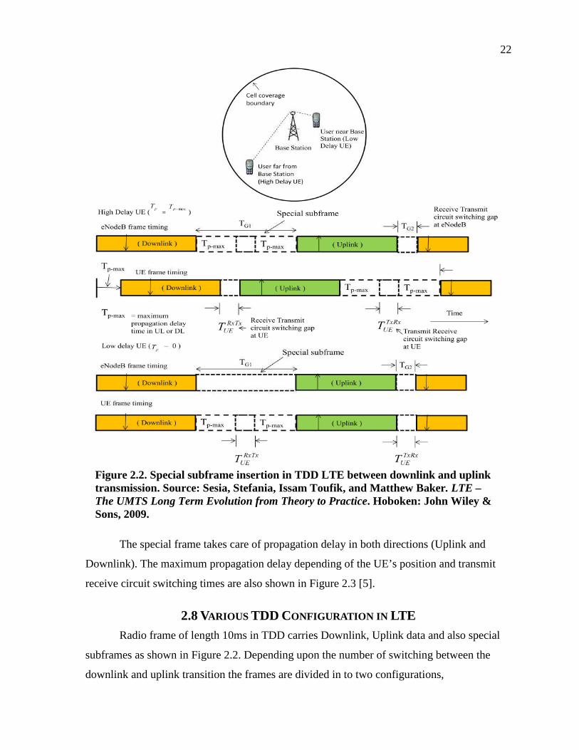
22
Figure 2.2. Special subframe insertion in TDD LTE between downlink and uplinktransmission. Source: Sesia, Stefania, Issam Toufik, and Matthew Baker. LTE –The UMTS Long Term Evolution from Theory to Practice. Hoboken: John Wiley &Sons, 2009.
The special frame takes care of propagation delay in both directions (Uplink and
Downlink). The maximum propagation delay depending of the UE’s position and transmit
receive circuit switching times are also shown in Figure 2.3 [5].
2.8 VARIOUS TDD CONFIGURATION IN LTE
Radio frame of length 10ms in TDD carries Downlink, Uplink data and also special
subframes as shown in Figure 2.2. Depending upon the number of switching between the
downlink and uplink transition the frames are divided in to two configurations,
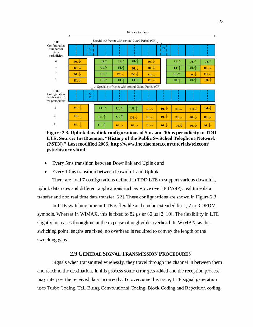
23
Figure 2.3. Uplink downlink configurations of 5ms and 10ms periodicity in TDDLTE. Source: InetDaemon. “History of the Public Switched Telephone Network(PSTN).” Last modified 2005. http://www.inetdaemon.com/tutorials/telecom/pstn/history.shtml.
Every 5ms transition between Downlink and Uplink and
Every 10ms transition between Downlink and Uplink.
There are total 7 configurations defined in TDD LTE to support various downlink,
uplink data rates and different applications such as Voice over IP (VoIP), real time data
transfer and non real time data transfer [22]. These configurations are shown in Figure 2.3.
In LTE switching time in LTE is flexible and can be extended for 1, 2 or 3 OFDM
symbols. Whereas in WiMAX, this is fixed to 82 μs or 60 μs [2, 10]. The flexibility in LTE
slightly increases throughput at the expense of negligible overhead. In WiMAX, as the
switching point lengths are fixed, no overhead is required to convey the length of the
switching gaps.
2.9 GENERAL SIGNAL TRANSMISSION PROCEDURES
Signals when transmitted wirelessly, they travel through the channel in between them
and reach to the destination. In this process some error gets added and the reception process
may interpret the received data incorrectly. To overcome this issue, LTE signal generation
uses Turbo Coding, Tail-Biting Convolutional Coding, Block Coding and Repetition coding

24
with various coding rates of 1/3 to 1/16 for different physical channels [11]. As there are
many users using the system simultaneously, Security of the data and control channels for
their data and control channel is maintained with the help of scrambling process [22]. Also
various data and control channels specific to the eNodeB are scrambled using eNodeB
specific codes [11]. The signal generation procedure in LTE is shown in Figure 2.4 [22].
Figure 2.4. LTE physical layer signal generation procedure block diagram. Source:3rd Generation Partnership Project. “Index of /ftp/Specs/archive/36_ series/36.211.”Last modified 2011. http://www.3gpp.org/ftp/Specs/archive/ 36_series/36.211/.
2.10 CELL SYNCHRONIZATION PROCESS
Matching up with time and frequency parameters of the reference or source is called
synchronization. In case of LTE networks, eNodeB is the source which controls access to the
UE. Hence, UE should adjust its frequency and time according to the eNodeB. This is done
with the help of special ZC sequences having good time synchronization properties as
discussed previously. eNodeB transmits these sequences periodically so that all UEs can
synchronize to the reference accordingly. There are three synchronization requirements in
LTE: symbol timing acquisition by which the correct symbol start is determined; carrier
frequency synchronization which mitigates the effect of frequency errors resulting from
Doppler shift and errors from electronics; and sampling clock synchronization. This is
achieved by two types of sequences called as Primary Synchronization Sequences (PSS) and
Secondary Synchronization Sequences (SSS).

25
2.10.1 Primary and Secondary SynchronizationSequences
PSS and SSS synchronization signals are used in cell search process where slot start
time, frequency offset and physical layer ID is achieved after detecting PSS. Whereas
detection of SSS gives radio frame timing, cell ID, Cyclic prefix length and TDD/FDD frame
system configuration [22]. PSS sequences are length 64 ZC sequences which have best
synchronization properties and SSS sequences are length M sequences which also have good
timing synchronization properties [2]. These signals are transmitted twice per 10 ms radio
frame. The PSS is located in the last OFDM symbol of the first and 11th slot of each radio
frame which allows the UE to acquire the slot boundary timing independent of the type of
cyclic prefix length. The PSS signal is the same for any given cell in every subframe in
which it is transmitted. The location of the SSS immediately precedes the PSS – in the before
to last symbol of the first and 11th slot of each radio frame. The UE would be able to
determine the CP length by checking the absolute position of the SSS. The UE would also be
able to determine the position of the 10 ms frame boundary as the SSS signal alternates in a
specific manner between two transmissions [22].
2.10.2 PSS and SSS Location in Frequency Domain
In the frequency domain, the PSS and SSS occupy the central six resource blocks,
irrespective of the system channel bandwidth, which allows the UE to synchronize to the
network without a priori knowledge of the allocated bandwidth. The synchronization
sequences use 62 sub-carriers in total, with 31 sub-carriers mapped on each side of the DC
sub-carrier which is not used. This leaves 5 sub-carriers at each extremity of the 6 central
RBs unused. PSS and SSS locations in a radio frame are shown in Figure 2.5 [2].
2.11 COMMUNICATION BETWEEN UE AND ENODEB
The communication between any two terminals is generally carried out with the help
of mutually agreed protocol structure. The two devices follow the procedure defined in the
protocol to communicate with each other; this is similar to the talking in one language that is
common between two persons. In Wireless communication, there are two types of
information transmitted (i) Data and (ii) control signals that help maintaining the
communication between UE and eNodeB and sharing data between them.

26
Figure 2.5. PSS and SSS structure in TDD and FDD with physical mapping inresource elements. Source: Sesia, Stefania, Issam Toufik, and Matthew Baker.LTE – The UMTS Long Term Evolution from Theory to Practice. Hoboken: JohnWiley & Sons, 2009.

27
For this communication and data transfer, LTE uses physical channels known as data
channels and control channels. Depending upon the direction of the data flow these are
further divided in to two types, Downlink data and control channels used for transferring data
and control signal from eNodeB to UE respectively. And second is, uplink data and control
channels, used to transmit data and control information from UE to eNodeB. These
Downlink and Uplink channels along with their physical mapping to the time and frequency
resources are explained in the next section.
2.12 LTE DOWNLINK PHYSICAL DATA AND CONTROL
CHANNELS
In this section the data and control channels are explained along with their
modulation, coding and physical mapping details which will be useful while comparing with
WiMAX.
2.12.1 Physical Broadcast Channel (PBCH)
When the users try to communicate first time with eNodeB they have very limited
information about the system parameters. Hence there is a need of some robust and fixed
location information block in the frame structure that can provide all necessary information
for establishing a connection. In LTE this is provided by Physical Broadcast Channel
(PBCH) [22]. The PBCH broadcasts a limited number of parameters essential for initial
access of the cell such as downlink system bandwidth, the Physical Hybrid ARQ Indicator
Channel structure, and initial ranging information. These parameters are carried in what’s
called a Master Information Block which is 14 bits long. The PBCH is designed to be
detectable without prior knowledge of system bandwidth and to be accessible at the cell
edge. The MIB is coded with convolutional coder at a very low coding rate of 1/3 (effective
coding rate is 1/48) and mapped to the 72 center sub-carriers (6RBs) of the OFDM structure.
PBCH transmission is spread over four 10 ms radio frames to span a 40 ms period as shown
in Figure 2.6 [2]. Each subframe is self decodable which reduces latency and UE battery
drain in case of good signal quality, otherwise, the UE would ‘soft-combine’ multiple
transmissions until the PBCH is decoded.

28
Figure 2.6. Physical mapping of PBCH. Source: Sesia, Stefania, Issam Toufik, andMatthew Baker. LTE – The UMTS Long Term Evolution from Theory to Practice.Hoboken: John Wiley & Sons, 2009.
In WiMAX the similar broadcast channel is transmitted to inform the system
configuration parameters with QPSK modulation and convolutional coder with basic coding
rate of ¼ and effective coding rate of 1/24. LTE broadcast channel as having lower coding
rate as compared to WiMAX, can be detected at the cell edge with low SNR [22].
2.12.2 Physical Downlink Shared Channel (PDSCH)
User data is communicated in the downlink on time and frequency resource called as
Physical Downlink Shared Channel (PDSCH). PDSCH is the main data carrying channel in
LTE which is scheduled to users by eNodeB. This is used in carrying downlink data per
Resource Block basis, system information not carried by PBCH and paging information. The
data from higher layer (MAC) layer comes with periodicity of 1ms, which is subframe
duration. This data can be assigned to one subframe or can be divided in to two parts and
assigned to the different slots of the different subframes to gain from frequency diversity

29
[22]. This is shown in Figure 2.7 [22]. If the data is assigned to both the slots in a subframe
then it is called localized mapping and if it is assigned to different slots of different subframe
then it is called as distributed mapping of data.
Figure 2.7. Distributed mapping of the userdata to distributed slots in the PDSCH.Source: 3rd Generation Partnership Project.“Index of /ftp/Specs/archive/36_series/36.211.” Last modified 2011. http://www.3gpp.org/ftp/Specs/archive/36_series/36.211/.
Distributed mapping of data achieves gain from the frequency diversity. This type of
distributed mapping is not present at the slot level in WiMAX. Hence LTE data may be
detected in the distributed mapping scheme with low SNR at the UE. The data is modulated
using QPSK, 16QAM or 64 QAM adaptively to achieve best system throughput. To guard
against propagation channel errors, convolutional turbo coder is used for forward error
Correction with basic rate of 1/3 [11].
2.12.3 Downlink Control Channels
The Resource Blocks are assigned to the UEs on demand and depending on the data
type. Control channels are used to indicate users the place in a time and frequency grid at
which their data is placed. Also the resource allocated for Uplink transmission for an UE is

30
also indicated by control channels. The structure and mapping of the Downlink Control
Channels is given in the next section.
2.12.4 Physical Downlink Control Channel (PDCCH)
Downlink Control channel (PDCCH) is assigned to occupy the first 1, 2 or 3 OFDM
symbols in a subframe of each subframe, extending over the entire system bandwidth [22].
The information about number of symbols is conveyed by PCFICH (covered in the next
section). This control channel carries resource allocation information in downlink and uplink
which is contained in a Downlink Control Information (DCI) message, ranging control
information and Hybrid Automatic Repeat Request (HARQ) information which is nothing
but acknowledgements to the UEs indiating packets received by eNodeB. This channel is
modulated with QPSK and coded with tail biting convolutional coding with coding rate of
1/3. The physical mapping can be shown in Figure 2.8 [2].
Figure 2.8. PDCCH physical mapping in thesubframe. Source: Sesia, Stefania, IssamToufik, and Matthew Baker. LTE – TheUMTS Long Term Evolution from Theory toPractice. Hoboken: John Wiley & Sons, 2009.

31
2.12.5 Physical Control Format Indicator Channel(PCFICH)
The PCFICH carries a Control Format Indicator (CFI) which indicates the number of
OFDM symbols (i.e. normally 1, 2 or 3) used for transmission of control channel information
in each subframe. This is done by 4 orthogonal codes assigned for each number of symbols
in the Control channel. Orthogonal codes are 32 bits and are modulated with QPSK
modulation and mapped to the 16 Resource elements at fixed location. The cell specific
offset and scrambling sequence is applied to this data to minimize interference from other
neighboring cell transmissions [22]. PCFICH is shown in Figure 2.9 [2].
Figure 2.9. PCFICH mapping on to physical resource elements. Source: Sesia,Stefania, Issam Toufik, and Matthew Baker. LTE – The UMTS Long Term Evolutionfrom Theory to Practice. Hoboken: John Wiley & Sons, 2009.
2.13 PHYSICAL UPLINK DATA AND CONTROL CHANNELS
There are numerous control channels used in LTE for effective communication and
can be explained as,
2.13.1 Physical Uplink Shared Channel (PUSCH)
Users send data to the eNodeB using this channel. It supports QPSK, 16 QAM and 64
QAM modulation scheme with a turbo coded data of mother rate of 1/3 [22]. The main
difference between downlink and uplink in LTE and other uplink technologies such as
WiMAX, is that LTE uplink technology uses SC-FDMA. The uplink data from higher layer
(MAC) comes to physical at the interval of 1ms which is similar to downlink [26]. This block
of data can be fragmented in two parts and can be assigned to different slots of different
Resource Blocks to gain frequency diversity as in downlink. Also the blocks from MAC
layer can be grouped together to be sent continuously to minimize the overhead of higher
layers and improve the performance. Being SC-FDMA modulated technology, it saves
battery power by reducing PAPR of the modulated signal.

32
2.13.2 Physical Uplink Control Channel (PUCCH)
This channel transmits uplink control information from UE to eNodeB. The resources
required for UE to transmit data to eNodeB are requested on this channel with the help of
predefined communication protocol. PUCCH also carry other uplink control messages which
include HARQ ACK/NACK, channel quality indicators, MIMO feedback and scheduling
requests [22]. PUCCH uses BPSK or QPSK as modulation scheme and block codes or tail
biting convolutional codes with rate of 1/3 as a modulation scheme. These control messages
are placed at the edge of the bandwidth to gain frequency diversity as shown in Figure 2.10
[2].
Figure 2.10. Physical uplink control channel mapping to physicalresources. Source: Sesia, Stefania, Issam Toufik, and MatthewBaker. LTE – The UMTS Long Term Evolution from Theory toPractice. Hoboken: John Wiley & Sons, 2009.
2.13.3 Physical Random Access Channel (PRACH)
User Equipments, after having downlink synchronization, also perform uplink
synchronization to connect to the eNodeB. This uplink timing and frequency synchronization
is done with the help of PRACH. As in downlink synchronization, uplink synchronization is
also done with the help of ZC sequences due to their properties discussed previously. As the

33
sequence is transmitted from UE with limited battery power, the length of the sequence is
increased to increase SINR at the eNodeB. This also helps increasing the coverage of the cell
[2]. This change in length forces to change the frequency spacing between subcarriers, which
is the most important change in the physical layer parameters. To fit the preamble in one
subframe length and keep other parameters and data transmissions from connected users safe,
the preamble duration of 800 μs with cyclic prefix of 103μs and guard time of 97 μs is
chosen. This can cover cell radius of 14km. The PRACH transmission slot consists of 72
sub-carriers in the frequency domain (six Resource Block, 1.08 MHz) as shown in Figure
2.11 [2].
Figure 2.11. PRACH preamble sequence structure and physical mappingto subcarriers Source: Sesia, Stefania, Issam Toufik, and Matthew Baker.LTE – The UMTS Long Term Evolution from Theory to Practice. Hoboken:John Wiley & Sons, 2009.
2.14 LTE CELL SEARCH PROCEDURE
A UE (User Equipment) willing to access an LTE cell must first undertake a cell
search procedure. Cell search procedure is a group of procedures which consists of a series of

34
synchronization stages through which the UE determines time and frequency synchronization
parameters that are necessary to demodulate the downlink data and to transmit in uplink slot
with the correct timing so as the signal maintains orthogonality with other users. The cell
search procedure is divided in steps of, Downlink synchronization, Uplink synchronization
and New cell Identification or Initial Synchronization network entry.
2.14.1 Downlink Synchronization
This is the first step in cell search. To start synchronization, UE should understand the
time clock and frequency on which eNodeB is working. For this UE after powering up
performs the downlink synchronization which is detection of PSS and SSS and acquiring
time, frequency and system configuration information from broadcast channel as discussed in
precious sections [22].
2.14.2 Uplink Synchronization
After downlink synchronization, the UE has synchronization with eNodeB clock and
frequency. In addition, to obtain the uplink timing advance information from eNodeB, UE
performs transmits one of the ranging code supported in the system and waits for the ranging
reply in the downlink control channel [2]. Once the ranging is successful, UE receives the
message and new dedicated ranging code with temporary ID in the downlink control channel.
If the ranging successful message is not received, then UE tries again till it succeeds.
2.15 NEW CELL IDENTIFICATION OR INITIAL
SYNCHRONIZATION
If the UE is already registered with one eNodeB and moving out of coverage area
then new cell identification procedure is carried out where the connected eNodeB assists the
UE in ranging and registration to the new cell [2]. UE is assigned with a dedicated ranging
sequence and then ranging is performed with the new cell. Whereas in case of initial
synchronization, the UE performs ranging procedure on the contention basis. The cell entry
procedure is explained in the next section. The initial synchronization steps are shown in
Figure 2.12 [2].

35
Figure 2.12. Initial cell synchronization steps in LTE. Source: Sesia, Stefania,Issam Toufik, and Matthew Baker. LTE – The UMTS Long Term Evolutionfrom Theory to Practice. Hoboken: John Wiley & Sons, 2009.
2.15.1 Contention Based Network RegistrationProcess
In initial synchronization and cell entry procedure, UE performs contention based
ranging. This is a four step process which involves sending signals in the uplink and
checking the reply message for the results. When UE performs initial downlink
synchronization it is not fully connected to the network. That means that it can only listen to
the downlink broadcast message but it cannot send data in the uplink or receive data in the
downlink. This is because, eNodeB schedules the resources and informs the UE accordingly.
If UE is not registered, then eNodeB cannot schedule resources to it. UE completes the
registration process with the help of ranging procedure and higher level layer messages
(L2/L3) [2]. The steps for contention based ranging in Figure 2.13 [19].
2.15.1.1 STEP1: PREAMBLE TRANSMISSION
In this step, The UE selects one of the 64 available PRACH contention based
signatures, which are indicated by downlink broadcast channel and transmits the preamble in
the uplink direction to the eNodeB. The transmission time and frequency resources are also
indicated by PBCCH [22]. After transmitting the ranging preamble UE goes to step 2 where
it waits for the response from eNodeB.

36
Figure 2.13. Cell search steps in LTE. Source: 3rd Generation Partnership Project.“Index of /ftp/Specs/archive/36_series/36.201.” Last modified 2010.http://www.3gpp.org/ftp/Specs/archive/36_series/36.201/.
2.15.1.2 STEP 2: RANDOM ACCESS
RESPONSE
eNodeB receives and detects all signatures transmitted in the uplink direction.
Random Access Response (RAR) is sent by eNodeB on the Physical Downlink Shared
CHannel (PDSCH), and addressed with an ID, the Random Access Radio Network
Temporary Identifier (RA-RNTI), identifying the time-frequency slot in which the preamble
was detected [2]. If multiple UEs had collided by selecting the same signature in the same
preamble time-frequency resource, they would each receive the RAR. The RAR conveys the
identity of the detected preamble, a timing alignment instruction to synchronize subsequent
uplink transmissions from the UE, an initial uplink resource grant for transmission of the
Step 3 message, and an assignment of a Temporary Cell Radio Network Temporary Identifier
(C-RNTI). If UE receives the response then it goes to step 3 or, If the UE does not receive a
RAR within the configured time window, it retransmits the preamble.

37
2.15.1.3 STEP 3: LAYER2/LAYER3 (L2/L3)MESSAGE
Layer2 and Layer3 messages are higher layer messages that contain the IDs of the UE
which is used by the higher layers. UE will now transmit the unique UE ID number along
with the C-RNTI allocated in the step 2 . In case of a preamble collision having occurred at
Step 1, the colliding UEs will receive the same Temporary C-RNTI through the RAR and
will also collide in the same uplink time-frequency resources when transmitting their L2/L3
message. However, if one UE is successfully decoded, the contention remains unresolved for
the other UEs. The following downlink message (in Step 4) allows a quick resolution of this
contention.
2.15.1.4 STEP 4: CONTENTION RESOLUTION
MESSAGE
The contention resolution message is addressed to the C-RNTI or Temporary C-
RNTI, and, in the latter case, echoes the UE identity contained in the L2/L3 message. It
supports HARQ. In case of a collision followed by successful decoding of the L2/L3
message, the HARQ feedback is transmitted only by the UE which detects its own UE
identity (or C-RNTI); other UEs understand there was a collision, transmit no HARQ
feedback, and can quickly exit the current random access procedure and start another one.
2.15.2 Contention-Free Random Access Procedure
In the scenarios where handover and resumption of downlink traffic for a UE, the
dedicated signature can be assigned to the UE and then UE can use that signature for ranging.
This provides definite way to assign and detect the ranging sequence so as to estimate the
time delay and network channel parameters. The steps involved in this can be shown in
Figure 2.14 [2].
In this procedure current eNodeB assigns the ranging preamble sequence to the UE.
The fixed ranging preamble transmitted by the UE is detected by the neighbor Base Station
to detect time advance and channel properties.
After this synchronization and Registration process, the effective connection between
UE and eNodeB is established. UE and eNodeB can now transfer the data to and fro using
this connection and downlink and uplink control channels. Various services are provided by

38
Figure 2.14. Contention free random access procedures in LTE.Source: Sesia, Stefania, Issam Toufik, and Matthew Baker. LTE – TheUMTS Long Term Evolution from Theory to Practice. Hoboken: JohnWiley & Sons, 2009.
eNodeB to UE using different predefined signals and messages. The users are now fully
synchronized at this stage and can benefit from the services provided.
In the similar way, next chapter discusses, IEEE 802.16m air interface physical layer
structures and procedures. The physical layer for IEEE 802.16m (Mobile WiMAX, but for
shortness it is referred as WiMAX) has many similarities as LTE physical layer. The working
however is slightly difficult giving some different system performance results. The working
and performances are discussed in the following chapter.

39
CHAPTER 3
STUDY OF MOBILE WIMAX
3.1 INTRODUCTION
Development of silicon industry and invention of computers throttled the further
technological advancements. The benefits to connect computers for sharing information have
motivated researchers to invent networks. Robert Metcalfe studied a concept ALOHAnet as
his PhD thesis in 1972 and developed Ethernet at Xerox corporation in 1973 [27]. The wired
network technologies were developed since the invention of Ethernet and Institute of
Electrical and Electronics Engineer (IEEE) standardized the first wireless LAN (IEEE
802.11) in 1997. First IEEE 802.11 standard produced data rates of 1Mbits/s and 2Mbits/s
[28]. Improvement in technology and constant efforts from IEEE have given newer standards
such as IEEE 802.11n which can transfer data with 135 Mbits/s. These wireless networks
however have limited coverage range.
To improve coverage and achieve same or improved data transfer rate as IEEE 802.11
standards, a new standard group was formed by IEEE in 1999. This new study group was
named as Worldwide Interoperability for Microwave Access (WiMAX) and published its
first standard IEEE 802.16 in December 2001 which delivered point to multipoint Broadband
Wireless transmission in the 10–66 GHz band, with only a line-of-sight (LOS) capability
[27]. Improvements continued and newer standards (IEEE 802.16a) for N-LOS and
frequency range of 2 GHz to 10 GHz were introduced. IEEE 802.16a introduced Orthogonal
Frequency Division Multiple Access (OFDMA) as a new modulating scheme for improved
data rate and overall performance. These all standard worked well for fixed application. A
need of standard with coverage of existing cellular technologies and data rates of wireless
LAN motivated development of new IEEE 802.16m (mobile WiMAX) standard with
mobility support, published in march 2011.
Mobile WiMAX supports peak data rates of 161 Mbps in the Downlink and 92 Mbps
in the Uplink in 20 MHz bandwidth. Mobile WiMAX also supports mobility up till 350
Km/Hr [10]. This chapter discusses physical layer structures and procedures of Mobile

40
WiMAX including modulation schemes, frame structures and physical channels. Chapter
starts the discussion with IEEE 802.16m physical layer general description.
3.2 IEEE 802.16M PHYSICAL LAYER GENERAL
DESCRIPTION
Mobile WiMAX (IEEE 802.16m) is basically developed to meet the IMT Advanced
requirements for 4G networks. 4G communication specifications are finalized by ITU as
IMT-Advanced. IMT-Advanced has provided a global framework for the development of 4G
systems that enable low-delay, high-speed, bi-directional data access, unified messaging, and
broadband wireless multimedia in the form of new service classes [23].
To meet the requirements for 4g system such as downlink data rate of 100 Mbps for
high mobility users, 1Gbps for fixed users, longer battery life of the user terminals operating
on battery, reduced cost of terminals and network equipments, IEEE finalized Orthogonal
Frequency Division Multiple Access (OFDMA) as Downlink and Uplink modulation
scheme. OFDMA gives best spectral efficiency and enable use of advanced Multiple Input
Multiple Output (MIMO) antenna techniques. MIMO further improves the data rate with
spatial multiplexing [10]. IEEE 602.16m is based on its previous version IEEE 802.16e. The
IEEE 802.16e physical layer structure was divided into small blocks of time and frequency,
hence two dimensional control signals data was required to convey the resources allocation
information from Base Station (BS) to users [29]. To avoid this overhead and to improve the
efficiency of the system, IEEE 802.16m adopts 20ms frame structure with single dimensional
resources which are discussed in the next section. For reference purposes the frame structure
for IEEE 802.16e is presented in Figure 3.1 [29].
3.3 PHYSICAL LAYER STRUCTURE OF IEEE 802.16M
To understand the working of the technology it is important to understand the
physical layer structure, modulation and coding scheme used in the technology. IEEE
802.16m works in 2.3 Ghz, 2.5GHz and 3.4GHz frequency bands. For variation of frequency
spectrum availability worldwide, flexible bandwidth of 5MHz, 10MHz and 20MHz is
supported. In addition to these changes, Mobile WiMAX uses modulation scheme OFDMA
for uplink and downlink to benefit from its best spectral efficiency. The OFDMA modulation
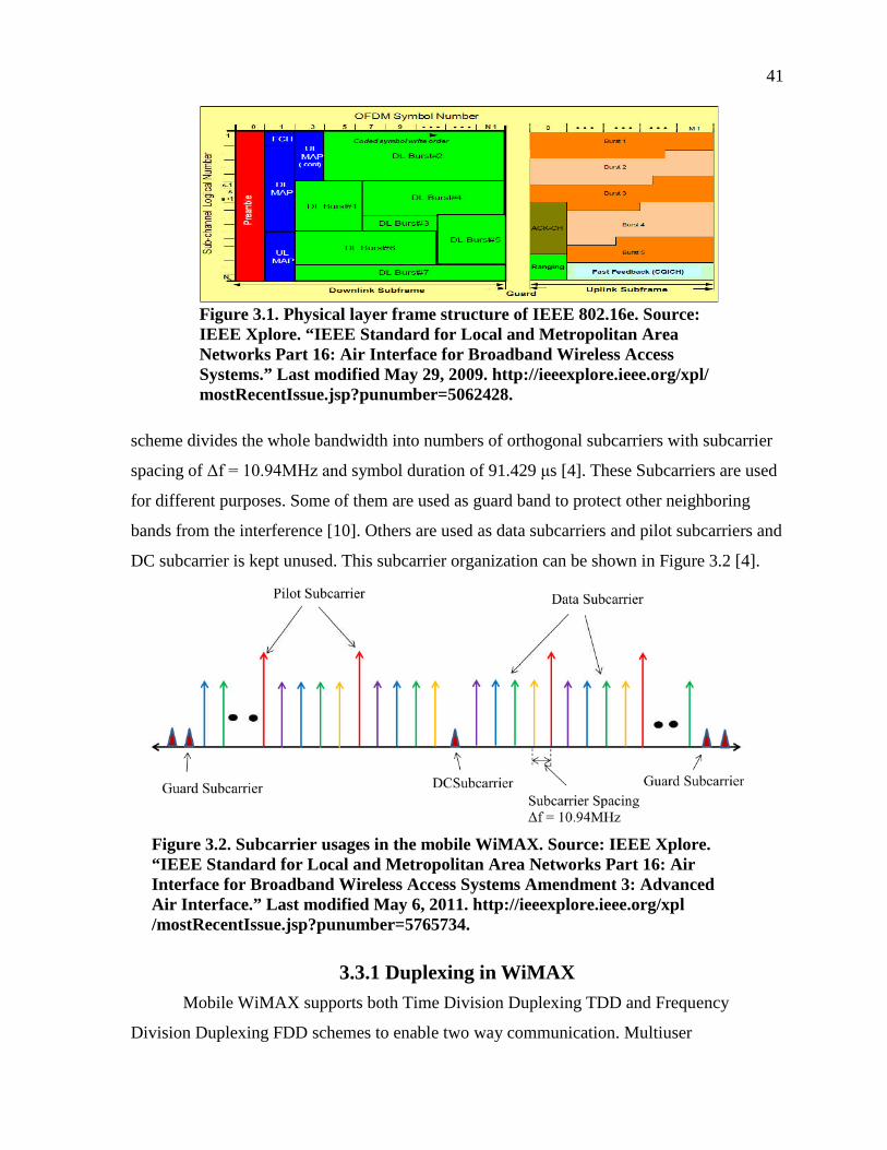
41
Figure 3.1. Physical layer frame structure of IEEE 802.16e. Source:IEEE Xplore. “IEEE Standard for Local and Metropolitan AreaNetworks Part 16: Air Interface for Broadband Wireless AccessSystems.” Last modified May 29, 2009. http://ieeexplore.ieee.org/xpl/mostRecentIssue.jsp?punumber=5062428.
scheme divides the whole bandwidth into numbers of orthogonal subcarriers with subcarrier
spacing of Δf = 10.94MHz and symbol duration of 91.429 μs [4]. These Subcarriers are used
for different purposes. Some of them are used as guard band to protect other neighboring
bands from the interference [10]. Others are used as data subcarriers and pilot subcarriers and
DC subcarrier is kept unused. This subcarrier organization can be shown in Figure 3.2 [4].
Figure 3.2. Subcarrier usages in the mobile WiMAX. Source: IEEE Xplore.“IEEE Standard for Local and Metropolitan Area Networks Part 16: AirInterface for Broadband Wireless Access Systems Amendment 3: AdvancedAir Interface.” Last modified May 6, 2011. http://ieeexplore.ieee.org/xpl/mostRecentIssue.jsp?punumber=5765734.
3.3.1 Duplexing in WiMAX
Mobile WiMAX supports both Time Division Duplexing TDD and Frequency
Division Duplexing FDD schemes to enable two way communication. Multiuser

42
configuration is supported by grouping together available time and frequency resources in a
small block containing 18 fixed subcarriers over 5,6 or 7 OFDM symbols (depending upon
the system configuration) [4]. One or more resources in the downlink are assigned to the
users in the Logical Resource Units (LRU) of 18 subcarriers and 6 OFDM symbols.
However, in the uplink, the resources are assigned in smaller LRUs known as tile having 4
subcarriers and 6 OFDM symbols. LRUs for downlink and uplink are shown in Figure 3.3
[4].
Figure 3.3. Uplink and downlink logical resource unit in WiMAX. Source: IEEEXplore. “IEEE Standard for Local and Metropolitan Area Networks Part 16: AirInterface for Broadband Wireless Access Systems Amendment 3: Advanced AirInterface.” Last modified May 6, 2011. http://ieeexplore.ieee.org/xpl/mostRecentIssue.jsp?punumber=5765734.
In LTE technology from 3GPP, the resource block of size 12 subcarriers of spacing
15KHz and symbol duration of 66.63 μs is used. Both size and index are required to be
specified in LTE to transmit the resource allocation information to the user. In WiMAX due
to the fixed structure (discussed in the next section), only index is sufficient to transmit the
resource allocation message. Hence controlling overhead in WiMAX is lower than in LTE.
This helps increasing WiMAX stem throughput by small amount [4, 19].

43
3.3.2 TDD and FDD Frame Structures in WiMAX
WiMAX supports both TDD and FDD techniques for two way data transfer, frame
structure for TDD and FDD uses same Downlink and Uplink subframes of 6 OFDM symbols
as described above. To achieve Mobility support, reduced latency and other requirements
from IMT Advanced, Mobile WiMAX uses 5ms basic frame structure. In FDD the subframes
are arranged one after the other in continuity. Whereas in TDD, there are two sections, one
for downlink data transfer and other is for uplink data transfer. These two sections are
separated by switching gap which helps to absorb propagation delay and switch from
receiving circuitry to transmit circuitry [10]. The 5ms frames for TDD and FDD are shown in
Figure 3.4.
Figure 3.4. Mobile WiMAX TDD and FDD radio frame for 10MHzbandwidth and DL/UL ratio of 5:3.
The switching gaps are further divided in two types of gaps known as Transmit
Transition Gap (TTG) which is before transmission of data is performed. Second type is
Receive Transition Gap (RTG) which is inserted before receiving of data is performed. The
gap durations are varied according to the Cyclic Prefix (CP) length [4]. The typical RTG and
TTG approximate time duration values for 1/8th and 1/16th of CP duration used in the mobile
WiMAX are 157 μs , 60 μs and 82 μs, 60 μs.

44
These duration for gap in LTE are flexible and can be adjusted to 1, 2 or 3 symbol
according to the channel conditions [19]. But these transition values are fixed for a fixed CP
duration in WiMAX. Hence, LTE gets a small amount of performance gain as compared to
IEEE 802.16m.
Signaling overhead is important parameter in determining the efficiency of the
communication system. Control and management signals are required for maintaining
communication and transferring data from one end to the other. Time and frequency
resources are used to transmit these control and management messages. However, if the
signaling and controlling overheads occupy more time and frequency resources, then the
overall system throughput is reduced [4]. To overcome this issue, Mobile WiMAX groups
together 4 radio frames of 5ms to form a superframe, which is discussed in the next section.
3.3.3 Superframe in Mobile WiMAX
In Mobile WiMAX the 5ms basic frames are combined to form a 20ms superframe.
At the beginning of the superframe there is a header called Primary Superframe header (P-
SFH) and secondary superframe header (S-SFH) which provide important system
information and initial network entry related parameters [10]. There are different types of
subframes defined as per the variation of number of OFDM symbols. Subframe type 1 – 4
consists of six, seven, five and nine OFDM symbols respectively. The uplink and downlink
subframes are provided in each 5ms subframe with a gap to provide the round trip delay
compensation and switching delay as discussed in the previous sections. The basic
superframe diagram can be shown in Figure 3.5 [10].
3.3.4 Superframe Header
Superframe Header is transmitted in the first subframe of a superframe and mapped to
the centre 72 subcarriers. Important information about system configuration and initial
synchronization is transmitted in the Superframe Header (SFH). As this is information is very
important, it is coded with the robust QPSK modulation scheme and coded with Tail Biting
Convolutional Code (TBCC) with the basic code rate of ¼ and effective code rate of 1/24 [4].
Due to this robust modulation and coding this broadcast information is easily available even
at the cell edge. SFH is divided in two information parts, Primary Superframe Header (P-
SFH) and Secondary Superframe Header (S-SFH). P-SFH is transmitted every 20ms and

45
Figure 3.5. Superframe structure in mobile WiMAX. Source: Ahmadi, Sassan.Mobile WiMAX A Systems Approach to Understanding IEEE 802.16m Radio AccessTechnology. Burlington: Elsevier Press, 2011.
contains system configuration messages. S-SFH is divided in to 3 parts Sub Packet 1 (SP1),
Sub Packet 2 (SP2) and Sub Packet 3 (SP3). SP1 includes information required for network-
reentry and it is transmitted every 40ms. SP2 contains information about initial network entry
and transmitted every 80ms. SP3 contains information required for maintaining
communication and transmitted every 160ms [4]. The physical mapping and time intervals
are indicated in Figure 3.6 [10].
When a signal is passed through the channel it is affected by the channel frequency
response. This includes but not limited to the combination of attenuation of certain
frequencies, propagation losses, phase shifts and shift in the frequency [29]. To obtain
maximum gain from available channel, the channel can be probed and signal transmission
can be assigned to the subcarriers which are least affected by channel [10]. In Mobile
WiMAX, this is achieved by grouping time and frequency resources in two types known as
localized and distributed way and assigning a physical resource from that group to users.
This is known as Subchannelization and Permutation in Mobile WiMAX, which is explained
in the next section.

46
Figure 3.6. Primary and secondary superframe headers. Source: Ahmadi,Sassan. Mobile WiMAX A Systems Approach to Understanding IEEE 802.16mRadio Access Technology. Burlington: Elsevier Press, 2011.
3.3.5 Subchannelization and Permutation in MobileWiMAX
Subchannelization and permutation is nothing but grouping of available subcarriers in
a localized, meaning contiguous subcarriers or distributed subcarriers. If the channel is not
flat over the frequency range then Distributed mapping is used [10]. And if the channel is flat
then data is sent over the group of adjacent subcarrier which is known as localized
Subchannelization. Grouping of the resources is done in 5 steps [4].
The process starts with partitioning available resources into numbers of Physical
Resource Unit (PRU, 18 subcarriers over 6 symbols). And it continues to group PRUs with
the help of partitioning permutation schemes specified in the standards. The final outcome is
Logical Resource Units (LRUs). Where LRUs contain Continuous Resource Units (CRU)
which is a group of localized subcarriers and Distributed Resource Units (DRU) which is a
group of distributed subcarriers.
These localized or distributed LRUs now can be assigned to the users in downlink
according to the channel response to achieve the best possible data throughput. However in

47
Uplink the LRUs are further subdivided in tiles as described in previous section and then
localized or distributed tiles can be assigned to users in the uplink.
The partition and permutation information is passed to users in the P-SFH broadcast
channel. Due to this partitioning, the two dimension time and frequency resource is
converted in to one dimension resource which can be specified by the index as shown in
Figure 3.7. Hence controlling and messaging overheads are less in Mobile WiMAX as
compared to LTE where both starting index and size are transmitted to the user. This helps
Mobile WiMAX to improve on saving the resources for more data transmission and gain
more system throughput.
Figure 3.7. Physical to logical resources generation in mobile WiMAX. Source: Ahmadi,Sassan. Mobile WiMAX A Systems Approach to Understanding IEEE 802.16m RadioAccess Technology. Burlington: Elsevier Press, 2011.

48
Physical layer structure provides foundation for the communication process where
various tasks make use of these structures to achieve different goals. Highly complex
communication process is break in to number of smaller parts and if all parts work
successfully, the whole process achieves the desired goals. One such small but important part
in the process is control channels, which are responsible for effective communication and are
discussed in the next section. The whole process is shown in Figure 3.7 [10].
3.4 CONTROL CHANNELS IN WIMAX
Control channels in WiMAX are mainly divided into two types, Downlink control
channels and uplink control channels. Control channels are mapped to the physical layer
section known as Advanced Management Access Protocol (A-MAP) region situated at the
first frequency partition. A-MAP section contains short Information Elements known as A-
MAP IEs which are Medium Access Control (MAC) messages. A-MAP IEs contains
information that either points to a physical resources or gives control information. Downlink
and uplink control channels are discussed next.
3.4.1 Downlink Control Channels
There are numerous downlink control channels that help in effective communication
between Base Station and Mobile station, and can be explained as,
3.4.1.1 NON USER SPECIFIC A MAPS
This is the first control channel that users decode to obtain the information for
decoding the assignment A-MAPs and HARQ feedback A-MAPs. The non-user specific A-
MAP IE carries 12 bits of information and is encoded using Tail Biting Convolutional Code
(TBCC) with an effective code rate of 1/12 and modulated with QPSK modulation [4]. The
non-user-specific A-MAP IE comprises: assignment A-MAP size, the number of assignment
A-MAPs in each assignment A-MAP group and HARQ feedback A-MAP related parameters.
All this information helps user to understand the other control channel sizes and formats
3.4.1.2 HARQ FEEDBACK A MAPS
The HARQ feedback A-MAP consists of HARQ feedback Information Elements
(IEs) to acknowledge success or failure of uplink data transmission. Each HARQ feedback
A-MAP IE carries one bit of information which is then repeated eight times. The resulting

49
bits are scrambled by the eight least significant bits of the Station Identifier (STID) of the
Mobile Station (MS) assigned during network entry [4]. Station Identifier is the unique
identification number assigned to the users during the initial network entry procedure [4].
This is used to scramble the HARQ message so that it should be only decodable to the
intended user. HARQ A MAP information in coded using TBCC with coding rate of 1/5.
3.4.1.3 POWER CONTROLA MAPS
The power control A-MAP contains closed-loop power control commands for uplink
transmission which are transmitted by the BS to every MS operating in closed-loop power
control mode. Controlling power at the MS is important factor to reduce the interference to
the other users and make sure of the reliable reception of the data transmitted by the MS [10].
Power Control A MAP IEs are coded using Tail biting Convolutional Coder with coding rate
of 1/5.
3.4.1.4 ASSIGNMENT A MAPS
This downlink control channel contains various types of control messages. These
mainly include uplink and downlink resource assignment messages, broadcast messages,
bandwidth request response messages and initial ranging response messages [10]. These
messages are 56 bit messages including 16 bit user specific CRC scrambling as discussed
above to make messages decodable to intended users. The coding scheme used is Tail Biting
Convolutional Coding with coding rate of 1/2, 1/4 of 1/8 and modulation used is QPSK.
Downlink control channels with SFH physical mapping is shown in Figure 3.8 [4].
3.4.2 Uplink Control Channels
As Mobile WiMAX supports Multiple Input Multiple Output (MIMO), the
information of channel is very important to benefit from MIMO. The channel information is
needed at both transmitter and receiver. This Channel Quality Indicators information (CQI)
transfer is done with the help of uplink control channels. Along with CQI, other information
such as HARQ feedback and initial ranging is transmitted with the help of uplink control
channels.

50
Figure 3.8. Downlink, uplink control channels and SFH physical mapping in mobileWiMAX. Source: IEEE Xplore. “IEEE Standard for Local and Metropolitan AreaNetworks Part 16: Air Interface for Broadband Wireless Access SystemsAmendment 3: Advanced Air Interface.” Last modified May 6, 2011.http://ieeexplore.ieee.org/xpl/mostRecentIssue.jsp?punumber=5765734.
3.4.2.1 FAST FEEDBACK CONTROL
CHANNELS
The uplink fast-feedback channel carries Channel Quality Indicators (CQI) and
MIMO feedback. There are two types of fast-feedback uplink control channels: Primary Fast-
Feedback Channel (PFBCH); and Secondary Fast-Feedback Channel (SFBCH). The PFBCH
carries 6 bits of information, providing wideband and narrowband channel quality and
MIMO feedback. It is used to support robust feedback reports. The SFBCH carries
narrowband CQI and MIMO feedback information. The number of information bits carried
in the SFBCH may vary from 7 to 24. These feedback channels use Space Time Coding
(STC) with variable rate which depends on feedback type [4]. The modulation scheme also
varies from QPSK to 16 QAM depending on the feedback type.

51
3.4.2.2 HARQ FEEDBACK CHANNEL
The HARQ feedback channels are used to carry ACK/NACK information
corresponding to downlink transmissions. The HARQ feedback channels start at
predetermined time offsets relative to the corresponding DL transmissions over an uplink
subframe.
3.4.2.3 SOUNDING CHANNEL
The sounding channel is used by a mobile station to send sounding signals for MIMO
feedback, channel quality feedback, and uplink channel measurement at the base station.
Furthermore, uplink sounding enables sounding-based downlink MIMO in TDD mode, and
uplink closed-loop MIMO in TDD and FDD modes. The sounding channel occupies specific
uplink sub-bands (narrowband sounding signal) or the entire bandwidth (wideband sounding
signal) over one OFDM symbol. With the help of signals transmitted on this subchannel Base
Station can estimate channel and use this estimation in MIMO operation [4]. The signals
transmitted on this channel are BPSK modulated Golay sequences of length 2048.
3.4.2.4 RANGING CHANNEL
This channel is very important in terms of initial ranging procedure and handover
ranging procedure. When user first powers up it synchronizes with the network time and
frequency with the help of Advanced Primary and Secondary synchronization signals. To
register with the network, uplink time synchronization is needed and it is done with the help
of initial ranging channel. When signals are transmitted from the user devices, they take
certain time to travel and reach the Base Station. This is called as propagation delay; this
delay is proportional to the distance between user and base station. To mach this time delay,
users have to advance the signals transmission.
This time delay is calculated by the base station with the help of ranging signals
transmitted by users on ranging channel. There are basically two types of ranging procedures,
Synchronized ranging and Non Synchronized ranging. Synchronized ranging procedure is
used when the user is uplink synchronized with the base station and wants to adjust the
uplink transmission time. Whereas, Non Synchronized ranging is done by the users having
no uplink synchronization with base station. Different types of sequences are used for

52
different ranging processes. The 256 ranging signals are divided in to four groups, initial
ranging, periodic ranging, handover ranging and bandwidth request.
3.4.2.4.1 Zadoff Sequences for NonSynchronized Ranging Process
To support the feature of initial ranging and handover ranging, Zadoff Chu signals
having idle autocorrelation property are selected [4]. Also to support larger coverage area,
longer length sequences are selected (length 139 or 557). To match the time duration of these
long sequences with the subframe time, the available frequency resource (Centre 72
Subcarriers) is divided into number of smaller subcarriers of spacing Δf/2 or Δf/8 for
sequence lengths of 139 and 557 respectively (Δf = normal subcarrier spacing of 10.94KHz).
Zadoff-Chu sequences with cyclic shifts are used to generate the ranging preamble codes for
non synchronized access and can be given as follows,
1,....1,0,)(
2)1(
RP
N
Nkkpkj
p Nkekx RP
CSp
Where NCS is unit cycle shift according to the cell size, p denotes the index of sequence
calculated by cyclic shift βp of the root sequence αp
3.4.2.4.2 Ranging Code Formats
There are two basic types of formats defined in the Ranging sequences, format 0 and
format 1for non synchronized ranging and Other is format for synchronized ranging process.
When the user is not synchronized with the base station, that is when it is in initial ranging
phase or handover phase, it selects format 0 or format 1 depending on the coverage size [4].
On the other hand, when user is synchronized with the base station, however needs to correct
the change in time advance due to change in distance, uses Synchronized ranging OFDM
symbol format structure. These two formats are shown in Figure 3.9 [4].
Mobile Users depending on the need, selects the ranging sequence and format and
transmits it in the respected resource lock indicated by Secondary Superframe header
Secondary Packet 2 (SP2) [4].

53
Figure 3.9. Ranging symbols and formats for synchronized and non synchronizedranging in WiMAX. Source: IEEE Xplore. “IEEE Standard for Local andMetropolitan Area Networks Part 16: Air Interface for Broadband WirelessAccess Systems Amendment 3: Advanced Air Interface.” Last modified May 6,2011. http://ieeexplore.ieee.org/xpl/mostRecent Issue.jsp?punumber=5765734.
3.4.2.5 BANDWIDTH REQUEST CHANNEL
A contention-based random access mechanism is used by the mobile stations to
transmit bandwidth request information to the base station. It uses synchronized ranging
OFDM symbol as described above [4].
Before performing uplink synchronization with the help of ranging channels, the User
device is required to acquire downlink time and frequency synchronization with the help of
Advanced Primary and Secondary Preambles [10]. This is discussed in the next section.
3.5 DOWNLINK SYNCHRONIZATION IN WIMAX
OFDMA is a modulation scheme where orthogonality is one of the dimension which
makes it more spectral efficient. To maintain this orthogonality and effective communication
with least interference between subcarriers and users, time and frequency synchronization is
the first step to enter the network. Without this synchronization demodulation of the
downlink data and uplink transmission is not possible. Mobile WiMAX uses Pseudo noise
(PN) sequences to achieve this synchronization [4, 30]. These sequences have best time

54
synchronization properties that help to achieve the synchronization. Use of these sequences is
discussed in the following sections.
3.5.1 Synchronization Channel in Mobile WiMAX
Synchronization in WiMAX is a two step process, first step is to achieve robust
timing synchronization through a PN sequence of length 216 called Primary Advanced
Synchronization Signal (PA Preamble), index of which also gives information about the
system bandwidth and subcarrier usage [10]. The second synchronization sequence called as
Secondary Advanced Signal (SA Preamble), on detection gives Cell ID number [4]. Fine
tuning of time and frequency is done with the secondary synchronization signal in the
frequency domain [3].
3.5.2 PA Preamble Physical Layer Mapping
PA Preamble is a narrowband synchronization Golay sequence signal of length 216
[4]. Timing synchronization is achieved by autocorrelation of repeated PA Preamble
sequences. The preamble is mapped to the alternate subcarriers in the frequency domain and
the remaining carriers are mapped to zero. This alternate mapping in the frequency domain
gives repeated waveform in the time domain which can be delayed and correlated with itself
to get the peak at the output of the correlator when two sequences match exactly. This
mapping is shown in Figure 3.10 [10].
Figure 3.10. PA preamble mapping in the frequency domain. Source: Ahmadi,Sassan. Mobile WiMAX A Systems Approach to Understanding IEEE 802.16mRadio Access Technology. Burlington: Elsevier Press, 2011.

55
3.5.3 PA preamble Detection
As discussed above, when alternate frequencies are modulated with PA Preamble
then there are two copies of the PA Preamble (PALL[n]) in the time domain. The PA Preamble
in time domain is shown in Figure 3.11.
Figure 3.11. PA preamble in time domain.
The received signal y[n] is delayed and correlated with itself to get the coarse time
synchronization. Simultaneously the received signal y[n] is crosscorrelated with the reference
copy the PA Sequence p[n] to achieve fine synchronization [31]. This process is shown in the
Figure 3.12.
Figure 3.12. Time synchronization with PA preamble in mobile WiMAX.

56
3.5.4 SA Preamble Physical Layer Mapping
SA Preamble is also a PN sequence generated with Golay Sequences of length 288
[4]. This is divided in to 8 parts. Different parts of SA Preamble are assigned to Macro Base
Station, Macro Hot Zone Base Station and Femto Base Station . These Base station are
supported and implemented to improve coverage area and reduce infrastructure cost [10].
The partition information about the SA Preamble is transmitted in the superframe header (S
SFH SP3). If a Femto BS is supported under a Macro BS then the SA Preamble portion
assigned to it is BPSK modulated its own Cell ID [4]. The information about the other
sections to modulate is obtained by backhaul network or by demodulating SA Preamble
transmitted by the supported BS. The eight segments are named as A,B,C,D,E,F,G and H.
and their partition for various supported bandwidth is shown in the Figure 3.13.
Figure 3.13. SA preamble partition in 8 segments in mobile WiMAX.
SA Preamble is transmitted every 10ms and PA preamble is transmitted every 20ms.
This configuration and mapping for TDD and FDD is shown in Figure 3.14 [10].
In Mobile WiMAX, PA Preamble periodicity is 20ms and SA Preamble periodicity is
10ms, Whereas in LTE, Primary Synchronization Signal (PSS) periodicity is every 5ms and
Secondary Synchronization Signal (SSS) is every 5ms. The average time delay for initial
synchronization for Mobile WiMAX could be larger as compared to LTE due to less
periodicity of the synchronization signals [4, 19].The latency measured in time for a user to
synchronize and register on the network is known as control plane latency. The control plane
latency for LTE is 50ms and for Mobile WiMAX is 70ms [4].

57
Figure 3.14. PA preamble and SA preamble frame structure in Mobile WiMAX.Source: Ahmadi, Sassan. Mobile WiMAX A Systems Approach to UnderstandingIEEE 802.16m Radio Access Technology. Burlington: Elsevier Press, 2011.
3.6 STATES IN MOBILE WIMAX
The user once connected to the network, transmits and receives data actively in the
call duration only. In the rest of the time duration apart from active data transmission and
reception, users can save battery by just staying synchronized and registered to the network
and start active data transmission and reception whenever needed. This is enabled by
defining various states in Mobile WiMAX. There are four states that help users to
communicate efficiently, conserve battery power and reduce the connection signaling
overhead on the base station. Next section discusses these four states [4].
3.6.1 Initialization State
Initialization state is the first state with which Mobile Stations (MS) starts after
powering up. There is no connection between MS and Base Station (BS) in this state. MS
synchronizes using primary and secondary synchronization signals and acquires Cell
identification and system configuration.

58
3.6.2 Access State
This state performs the network entry related procedures in the selected BS. It mainly
performs the following procedures.
Initial ranging and Uplink synchronization.
Basic capability negotiation.
Authentication, authorization and key exchange.
Registration with the BS.
Service flow establishment (IP connection).
After all of the above stages cleared, MS can connect to the BS to perform data
exchange procedures with BS.
3.6.3 Connected State
In this state, data transfer can be done in Uplink and Downlink direction. Also the
battery power can be saved when there is no data to transmit or receive. One more activity is
done in this state and that is it measure signal strength of neighboring cells so as to take
decision of handover. The connected state is divided into three modes to perform the
activities discussed as follows,
Active Mode: In this mode the BS can schedule uplink or downlink data transmissionfor MS. The MS helps BS to adapt suitable modulation and coding dependingschemes on the channel condition. MS measures channel condition by observingdownload Reference Signals (RS) and transmits the Channel Quality Information(CQI) to the BS. MS can transit from connected state to sleep or idle mode if there isnothing to transmit or receive.
Sleep mode: If there is no data sharing activity in the Uplink or Downlink directionthen to conserve battery power, MS can go in sleep mode for some pre negotiatedperiod. BS can trigger traffic indication message and transition MS to connected stateto transfer data.
Scanning Mode: MS keeps on scanning the neighboring BS RF signal strength tomake a decision on handover. In this state the MS is not available for connected BSfor data transfer. BS can also transit MS in to this mode by sending the MACmessage.
3.6.4 Idle State
Idle state allows MS to become periodically available for downlink broadcast
messages without registration at the specific base station as MS traverses across the network
populated by multiple base stations, and thus allows MS to conserve power and operation al

59
resources. There are two modes in the idle state; one is paging available and second is paging
unavailable. The MS may switch to and fro from paging available and unavailable also vice
versa. By doing this MS conserves power. In paging available mode MS may be paged by
BS. If the MS is paged by BS then it switches to the Access state for network entry. In the
paging unavailable mode the MS cannot be paged and MS does not monitor the downlink
channel in order to reduce the power consumption.
Using above states MS can stay connected with the BS, conserve battery power
whenever possible and also reduce the signaling overhead of the system. The state diagrams
are shown in Figure 3.15 [4].
3.6.5 Network Entry
Network entry is a series of sequences that MS goes through to connect to the Base
Station. In Mobile WiMAX user profiles are defined depending on the modulation schemes
supported at MS, configuration parameters and air interface protocol revision [4]. These
capabilities are also negotiated in network entry procedure. After downlink and uplink
synchronization, ranging procedures and basic capabilities negotiation, Authentication and
Registration processes the Mobile station receives a unique Connection Identifier (CID). BS
uses this CID as a reference to the MS. The network entry procedure can be shown in Figure
3.16 [4].
After network entry, communication and data sharing procedures are carried out with
the help of control channels and higher level messages (MAC) to benefit from the services
provided by the network.

60
Figure 3.15. User state interconnection and working diagrams in mobile WiMAX.Source: IEEE Xplore. “IEEE Standard for Local and Metropolitan Area NetworksPart 16: Air Interface for Broadband Wireless Access Systems Amendment 3:Advanced Air Interface.” Last modified May 6, 2011. http://ieeexplore.ieee.org/xpl/mostRecent Issue.jsp?punumber=5765734.

61
Figure 3.16. Network entry flow diagram in mobile WiMAX. Source: IEEE Xplore.“IEEE Standard for Local and Metropolitan Area Networks Part 16: Air Interfacefor Broadband Wireless Access Systems Amendment 3: Advanced Air Interface.”Last modified May 6, 2011. http://ieeexplore.ieee.org/xpl/mostRecentIssue.jsp?punumber=5765734.

62
CHAPTER 4
LTE AND WIMAX PHYSICAL LAYER
COMPARISON
4.1 INTRODUCTION
It always has been a race between the technologies trying to meet the standard
specifications and acquire the market chunk. In next generation 4G Wireless Communication
technologies Specified by ITU-Advanced [32], LTE and Mobile WiMAX are in the race.
Physical layer Design is the main key factor deciding the best performance achievable by the
system. It is a give and take approach; one parameter is selected over the others to achieve
the desired performance. These parameters are carefully selected to achieve the best overall
performance satisfying all standard 4G requirements. To decide the best performance
technology, all technologies are generally weighed in various aspects and then decision is
made based on the results.
In this chapter, two technologies LTE and WiMAX are compared based on their
physical layers to achieve the IMT-Advanced standard specifications for 4G wireless
networks [32]. International Telecommunication Union (ITU) is an international organization
decides the ITU-Advanced standards and also provides the test guidelines and procedures as
a common ground to test the candidate technologies [33]. The comparison between LTE and
WiMAX in this chapter is based on the test results submitted by the respective technology
development groups according to the ITU test guidelines ITU-R M.2133, ITU-R M.2134 and
ITU-R M.2135 [31, 34, 35]. Various aspects of technologies are compared such as,
Modulation techniques, multiplexing techniques, cell spectral efficiency, Voice over IP and
link budget parameters and conclusion is drawn on the basis of the comparison results at the
end. The chapter begins with the physical layer parameters of two technologies LTE and
WiMAX.
4.2 LTE AND WIMAX PHYSICAL LAYER PARAMETERS
Physical layer parameters are the important performance measures. If physical layer
is efficient in delivering the high data rate throughput, overall system capacity increases.

63
These parameters include frequency band of operation, modulation scheme used and
spectrum usage etc. LTE and WiMAX both use OFDMA as a modulation technique for
Downlink and Uplink. This divides the available frequency spectrum into number of
subcarriers as discussed in sections 2.3 in chapter II and 3.2 in chapterIII. In addition,
spectrum usage also influences system throughput. Due to out of band spurious emission
constraints, WiMAX can use 94% of the available spectrum and LTE can use 90% of the
available spectrum [4, 36]. This increased bandwidth efficiency help WiMAX increasing
overall system throughput as compared to LTE. To compare these physical layer parameters
a summary is given in Table 4.1 [25, 36].
In above table WiMAX is at higher side on number of subcarriers and available time
and frequency Resource elements (RE) than LTE. Resource Elements occupying one
subcarrier over one OFDM symbol are the basic data carrying entity in both LTE and
WiMAX.
Based on the above table available resources for data transfer in case of LTE and
WiMAX in 10MHz bandwidth can be calculated as number of Resource Elements (RE) =
total usable subcarriers x number of OFDM symbols in 10ms (Frequency x time). REs are
large in numbers in WiMAX than LTE which helps increasing overall system throughput.
Figure 4.1 and 4.2 are the graphs that compare number of subcarriers and Resource elements
used in 10MHz bandwidth for LTE and WiMAX.
4.3 CELL TYPES FOR SERVING DIFFERENT PRACTICAL
SCENARIO IN LTE AND WIMAX
Various cell types are defined to cater practical scenarios such as, cell coverage
radius, Base Station transmission power, number of users and mobility of the users.
Depending on these factors, various cell types are defined into four categories as discussed
below.
Indoor Hotspot (InH): This cell type posses very small range, small power, highthroughput and large number of users with pedestrian speed (3Km/Hr) or stationaryusers. Suitable for office area and indoor environment where high users are using thenetwork.
Urban Micro-cellular (UMi): this type of cell is used typically in city centers. Thiscell type is designed for small area (large compared to (InH) ), high density of users,user mobility is from pedestrian to vehicular speed and high data throughput.

64
Table 4.1. Physical Layer Parameters for LTE and WiMAX for Different BandwidthScenarios
Nominal Channel
Bandwidth
5 MHz 10MHz 15MHz
Technology LTE WiMAX LTE WiMAX LTE WiMAX
FFT Size 512 512 1024 1024 2048 2048
Sampling Rate (MHz) 7.68 5.6 15.36 11.2 30.72 22.4
Useful Symbol Time for
Extended CP Tu (μs).
66.66 114.286 66.66 114.286 66.66 114.286
Useful Symbol Time for
Normal CP Tu (μs).
69.046 97.143 69.046 97.143 69.046 97.143
Number of symbols per
10ms for TDD with normal
CP
140 100 140 100 140 100
Number of symbols per
10ms for TDD with
extended CP
120 84 120 84 120 84
Occupied Sub-Carriers 300 433 600 865 1200 1729
Sub-Carrier Spacing Δf
(kHz)
15 10.94 15 10.94 15 10.94
Number of Resource Blocks 25 24 50 48 100 96
Resource Elements Normal
CP (1 / 16 Tu )
42000 43300 84000 86500 168000 172900
Resource Elements Normal
CP (1 / 4 Tu )
36000 37372 72000 72660 144000 145236
Normal CP Size (μs)
(1 / 16 Tu )
4.69 5.71 4.69 5.71 4.69 5.71
CP Size (μs) (1 / 4 Tu ) 16.67 22.857 16.67 22.857 16.67 22.857
Source: International Telecommunications Union. “Acknowledgement of Candidate Submission from IEEEUnder Step 3 of the IMT-Advanced Process.” Last modified October 23, 2009. http://www.itu.int/md/R07-IMT.ADV-C-0004/en; 3rd Generation Partnership Project. “Index of /ftp/Specs/archive/36_series/36.912” Lastmodified March 2010. http://www.3gpp.org/ftp/Specs/archive/36_series/36.912/.

65
Figure 4.1. Comparison of subcarriers in LTE and WiMAX.
Figure 4.2. Comparison of resource elements in LTE andWiMAX.
Urban Macro-Cellular (UMa): This type of cell is of special interest as it is used tocover most of the urban area. This is designed for High power Base Station, largenumber of users with mobility from pedestrian speed to high speed vehicular speeds(up to 120 Km/Hr) and Non line of sight operation.
Rural Macro-Cellular (RMa): This type of cell is designed for wide coverage area,large Base Station power and very high speed users (up to 350 Km/Hr).
Results for InH show best throughput than others due to limited interference scenario
[10]. All other cell types show similar results and this result is limited by interference caused
by neighboring base stations. In a communication system, signaling and messaging overhead
play an important role in deciding the system throughput. Next section discusses the
overheads in LTE and WiMAX.
0
500
1000
1500
2000
5 MHz,512point FFT
10MHz, 1024point FFT
15MHz,2048point FFT
300600
1200
433
865
1729
Subca
rrie
rs
Bandwidth
Subcarriers used For LTE and WiMAX
LTE
WiMAX
0
50000
100000
150000
200000
5 MHz 10MHz 15MHz
42000
84000
168000
43300
86500
172900
Res
ourc
eE
lem
ents
Bandwidth
10ms radio frame Resource Elements For LTEand WiMAX
LTE
WiMAX

66
4.4 STATIC AND DYNAMIC OVERHEAD IN LTE AND
WIMAX
A static overhead channel requires fixed base station power, time slot, and/or
bandwidth. On the other hand, a dynamic overhead channel requires base station power,
time, and/or bandwidth which dynamically change over time as a function of the number of
active users. Static overhead include guard bands and primary and secondary time, frequency
synchronization signals as discussed in sections 2.7.1 in chapter II and 3.4 in chapter III.
Base Station power and bandwidth resources are utilized in the overheads minimizing the
effective system throughput. Hence it is desirable to minimize the system overheads.
Dynamic overheads on the other hands include control channels, HARQ ACK/NACK
feedbacks, Channel Quality feedback and random access channel. Dynamic overheads vary
as per the system configuration and number of users in the system [24, 37]. Following Figure
4.3 is the general diagram showing static and dynamic overheads.
Figure 4.3. General static and dynamic overheads in the LTE and WiMAX.
As discussed in section 4.1 WiMAX has less guard band overhead as compared to
LTE, hence WiMAX has lower static overheads. Dynamic overheads are calculated by
system level simulation varying the number of users, channel conditions, user data rates and
mobility conditions.
IEEE and 3GPP groups measure their system performance based on the ITU system
model and measurement procedures specified in ITU-R WP 5D, Report ITU-R M.2134 , 35
[34, 35]. Table 4.2 [25, 37] and Figure 4.4 summarize the Static and Dynamic overheads in
LTE and WiMAX based on ITU test procedures guidelines [24, 37].

67
Table 4.2. Total Static and Dynamic Overhead in LTE and WiMAX
Cell Type TDD Overhead in percentage
of total resources
FDD Overhead in percentage of
total resources
LTE Mobile WiMAX LTE Mobile WiMAX
UMa 14.3% 11.17% 14.3% 13.77%Source: International Telecommunications Union. “Acknowledgement of Candidate Submission from IEEEUnder Step 3 of the IMT-Advanced Process.” Last modified October 23, 2009. http://www.itu.int/md/R07-IMT.ADV-C-0004/en; 3rd Generation Partnership Project. “Index of /ftp/Specs/archive/36_series/36.912”Last modified March 2010. http://www.3gpp.org/ftp/Specs/archive/36_series/36.912/.
Figure 4.4. Total control overhead comparisons in LTE and WiMAX.
4.5 VOICE OVER IP (VOIP) CAPACITY OF LTE AND
WIMAX
LTE and WiMAX are Internet Protocol (IP) based networks as seen in chapter II and
chapter III. Voice communication in these networks is achieved by sending voice data
through IP packets; this is called as Voice over IP [38]. VoIP services provide great deal of
flexibility and services as compared to regular circuit switched voice calls.
LTE and WiMAX both support large numbers of simultaneous users and both exceed
the ITU standards by considerable margin. As WiMAX have benefit of more Resource
Elements in the same bandwidth and time over LTE, it supports more number of active VoIP
users than LTE. Table 4.3 [25, 37] and Figure 4.5 list the statistics of the test results collected
from 3GPP and IEEE test findings as per the ITU specification [24, 37].
0.00%
5.00%
10.00%
15.00%
TDD overhead FDD Uma overhead
14.30% 14.30%
11.17%
13.77%
Ov
erh
ead
inP
erce
nta
ge
Cell Type Urban Macro Cell
Static and Dynamic Overhead in LTE and WiMAX
LTE
Mobile WiMAX

68
Table 4.3. VoIP Capacity of LTE, WiMAX and ITU Requirement
Cell
Type
ITU Requirement (Active
Users/MHz/Cell)
TDD System Capacity
(Active
Users/MHz/Cell)
FDD System Capacity
(Active
Users/MHz/Cell)
LTE WiMAX LTE WiMAX
InH 50 137 140 131 139
UMi 40 74 82 75 77
UMa 40 67 74 69 72
RMa 30 92 89 90 90
Source: International Telecommunications Union. “Acknowledgement of Candidate Submission from IEEEUnder Step 3 of the IMT-Advanced Process.” Last modified October 23, 2009. http://www.itu.int/md/R07-IMT.ADV-C-0004/en; 3rd Generation Partnership Project. “Index of /ftp/Specs/archive/36_series/36.912”Last modified March 2010. http://www.3gpp.org/ftp/Specs/archive/36_series/36.912/.
Figure 4.5. TDD VoIP capacity of LTE and WiMAX.
4.6 CELL SPECTRAL EFFICIENCY OF LTE AND WIMAX
This parameter is nothing but the overall efficiency of radio resources, utilized to
deliver information bits to the users. The spectral efficiency depends on the modulation
technique such as QPSK, 16 QAM or 64 QAM, number of Resource elements available per
unit time in a given bandwidth and Multiple Input Multiple Output (MIMO) smart antenna
techniques used.
137
74
67
92
140
82
74
89
0 50 100 150
InH
UMi
UMa
RMa
Number of Users
Cell TypeTDD VoIP Capacity Of LTE and WiMAX
WiMAX
LTE

69
Cell Spectrum Efficiency is defined as, number of correctly received bits delivered to
the upper layers over a certain period of time, divided by the channel bandwidth divided by
the number of cells. This is measured in terms of bits/Seconds/Hertz/Cell. When multiple
users share the system at different distances from the base station, normalized cell spectral
efficiency for entire system is calculated by averaging over all user spectral efficiencies [32].
As user travels to the end of the cell coverage, the base station power decreases and
cell spectral efficiency also decreases to the large extent. Spectral efficiency at the edge of
the cell is known as Cell Edge Spectral efficiency, and it is calculated as 5% point of the
cumulative distribution function of the normalized user throughput.
System capacity is better if the cell spectral efficiency is large as system can support
more users and transfer more information bits. As WiMAX has more Resource elements
available, it can transfer more bits per unit time and achieve more spectral efficiency as
compared to LTE. Simulations results for cell spectral efficiency for various cell types and
downlink and uplink directions are summarized in the Table 4.4 [25, 37], Table 4.5 [25, 37]
and Figure 4.6 and Figure 4.7. Moreover, TDD and FDD results for uplink and downlink
show similar nature in results hence graphical representation for only one scenario is shown
as other scenarios exhibit the similar nature of the graph.
From the graphs it is clear that both technologies perform similarly and produces
similar results with WiMAX being at slightly higher side due to its more bandwidth
utilization factor (94%) as compared to LTE (90%). These cell efficiencies are actual
practical simulation results of the channel conditions, number of simultaneous users and
mobility conditions. We will now discuss the theoretical peak spectral efficiency which can
be possible in the idle conditions.
4.7 PEAK SPECTRAL EFFICIENCY OF LTE AND WIMAX
This is the highest possible theoretical data rate transmitted to a single mobile station
normalized by bandwidth, assuming error-free transmission and all radio resources are fully
utilized. Radio resources utilized for physical layer synchronization, Reference signals and
guard band, guard times are not considered in this calculation. This measure helps
understanding the maximum capacity limit of the system.
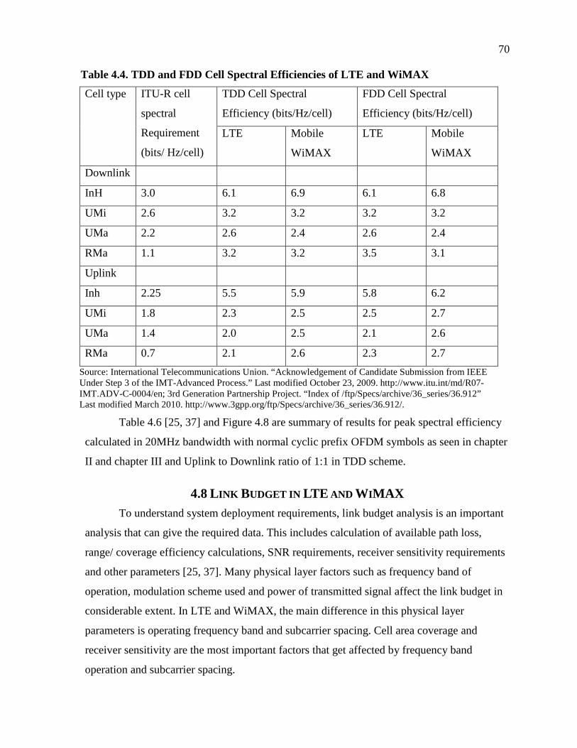
70
Table 4.4. TDD and FDD Cell Spectral Efficiencies of LTE and WiMAX
Cell type ITU-R cell
spectral
Requirement
(bits/ Hz/cell)
TDD Cell Spectral
Efficiency (bits/Hz/cell)
FDD Cell Spectral
Efficiency (bits/Hz/cell)
LTE Mobile
WiMAX
LTE Mobile
WiMAX
Downlink
InH 3.0 6.1 6.9 6.1 6.8
UMi 2.6 3.2 3.2 3.2 3.2
UMa 2.2 2.6 2.4 2.6 2.4
RMa 1.1 3.2 3.2 3.5 3.1
Uplink
Inh 2.25 5.5 5.9 5.8 6.2
UMi 1.8 2.3 2.5 2.5 2.7
UMa 1.4 2.0 2.5 2.1 2.6
RMa 0.7 2.1 2.6 2.3 2.7
Source: International Telecommunications Union. “Acknowledgement of Candidate Submission from IEEEUnder Step 3 of the IMT-Advanced Process.” Last modified October 23, 2009. http://www.itu.int/md/R07-IMT.ADV-C-0004/en; 3rd Generation Partnership Project. “Index of /ftp/Specs/archive/36_series/36.912”Last modified March 2010. http://www.3gpp.org/ftp/Specs/archive/36_series/36.912/.
Table 4.6 [25, 37] and Figure 4.8 are summary of results for peak spectral efficiency
calculated in 20MHz bandwidth with normal cyclic prefix OFDM symbols as seen in chapter
II and chapter III and Uplink to Downlink ratio of 1:1 in TDD scheme.
4.8 LINK BUDGET IN LTE AND WIMAX
To understand system deployment requirements, link budget analysis is an important
analysis that can give the required data. This includes calculation of available path loss,
range/ coverage efficiency calculations, SNR requirements, receiver sensitivity requirements
and other parameters [25, 37]. Many physical layer factors such as frequency band of
operation, modulation scheme used and power of transmitted signal affect the link budget in
considerable extent. In LTE and WiMAX, the main difference in this physical layer
parameters is operating frequency band and subcarrier spacing. Cell area coverage and
receiver sensitivity are the most important factors that get affected by frequency band
operation and subcarrier spacing.

71
Table 4.5. Cell Edge Spectral Efficiencies for LTE and WiMAX
Cell type ITU-R cell spectral
Requirement (bits/
Hz/cell)
TDD Cell Edge Spectral
Efficiency (bits/Hz/cell)
FDD Cell Edge Spectral
Efficiency (bits/Hz/cell)
LTE Mobile
WiMAX
LTE Mobile
WiMAX
Downlink
InH 3.0 0.24 0.26 0.24 0.253
UMi 2.6 0.096 0.092 0.22 0.097
UMa 2.2 0.082 0.069 0.073 0.069
RMa 1.1 0.089 0.093 0.099 0.091
Uplink
InH 2.25 0.39 0.426 0.42 0.444
UMi 1.8 0.071 0.111 0.086 0.119
UMa 1.4 0.097 0.109 0.099 0.114
RMa 0.7 0.093 0.119 0.13 0.124
Source: International Telecommunications Union. “Acknowledgement of Candidate Submission from IEEEUnder Step 3 of the IMT-Advanced Process.” Last modified October 23, 2009. http://www.itu.int/md/R07-IMT.ADV-C-0004/en; 3rd Generation Partnership Project. “Index of /ftp/Specs/archive/36_series/36.912” Lastmodified March 2010. http://www.3gpp.org/ftp/Specs/archive/36_series/36.912/.
Figure 4.6. Cell spectral efficiencies comparison of LTE and WiMAX.
0
1
2
3
4
5
6
7
InH UMi UMa RMa
6.1
3.22.6
3.2
6.9
3.2
2.43.2
bit
s/H
z/ce
ll
Cell Type
TDD Downlink Cell Spectral efficiency ForLTE and WiMAX
LTE
WiMAX

72
Figure 4.7. Uplink cell edge spectral efficiency comparison for LTEand WiMAX.
Table 4.6. Peak Spectral Efficiency for LTE and WiMAX
TDD Peak Spectral
Efficiency (bits/s/Hz)
FDD Peak Spectral
Efficiency (bits/s/Hz)
LTE Mobile
WiMAX
LTE Mobile
WiMAX
Downlink 16.0 16.13 16.3 17.37
Uplink 8.1 9.21 8.4 9.4
Source: International Telecommunications Union. “Acknowledgement of Candidate Submission from IEEEUnder Step 3 of the IMT-Advanced Process.” Last modified October 23, 2009. http://www.itu.int/md/R07-IMT.ADV-C-0004/en; 3rd Generation Partnership Project. “Index of /ftp/Specs/archive/36_series/36.912” Lastmodified March 2010. http://www.3gpp.org/ftp/Specs/archive/36_series/36.912/.
4.8.1 Inter Carrier Interference as a Function ofSubcarrier Spacing
The subcarrier spacing is an important factor that influences inter carrier interference
(ICI). Increase in ICI increases the Bit Error Rate (BER) and decreases system throughput
[13]. In practice, the sub-carrier spacing is not the same among different subcarriers due to
mismatched oscillators, Doppler shift, and timing synchronization errors, resulting in Inter-
Carrier Interference (ICI) and loss of orthogonality. ICI can be approximated as,
2
fICI k
0.39
0.071 0.097
0.093
0.426
0.111 0.109
0.119
0
0.05
0.1
0.15
0.2
0.25
0.3
0.35
0.4
0.45
InH UMi UMa RMa
bit
s/H
z/ce
ll
Cell Type
TDD Uplink Cell Edge Spectral efficiency ForLTE and WiMAX
LTE
WiMAX

73
Figure 4.8. Peal spectral efficiency comparison for LTE and WiMAX.
Where η is constant, Δf is subcarrier spacing and δ is frequency offset due to synchronization
mismatch, oscillator mismatch or Doppler frequency shift [10]. WiMAX selects subcarrier
spacing Δf = 10.94 KHz and LTE uses subcarrier spacing Δf = 15KHz. Hence ICI in LTE is
less as compared to WiMAX in normal operation and also in high Doppler spread operation
when user is moving at higher speeds [10]. This can be overcome by increasing Signal to
Noise Ratio (SNR) at the receiver to obtain desired BER. So for WiMAX required SNR is
larger than in LTE.
4.8.2 Propagation Losses and Operating Frequency
Propagation losses are the major losses that affect cell coverage area. These losses are
distance dependent. If a signal is transmitted with a power Pt then received signal power Pr is
dependent on the distance d and wavelength λ of the transmitted frequency. This can be
formulated as,
2
4
d
G
p
p l
t
r
Where lG is the product of the transmit and receive antenna field radiation patterns in LOS
direction [28]. For non directional antennas, the received power decreases with decrease in λ,
that is increase in frequency. WiMAX operates in the frequency bands of 2.3, 2.5 and 3.4
GHz, whereas LTE operates mainly in 900 MHz to1800 MHz frequency bands. Also
16
8.1
16.13
9.21
0
2
4
6
8
10
12
14
16
18
Downlink Uplink
bit
s/s/
Hz
Direction
TDD PeakSpectral efficiency For LTE andWiMAX
LTE
WiMAX

74
penetration loss of frequency band 2.3, 2.5 and 3.4 GHz band is more as compared to
1800MHz, 1900MHz frequency band [28]. Considering all these losses, receiver sensitivity
of the WiMAX receiver is increased to achieve the desired bit rate [13]. Penetration losses
directly affect data rate as lower received signal strength may force to adapt lower order
modulation schemes at the transmitter or increased BER.
4.8.3 Link Budget Comparison
Depending on the factors such as subcarrier spacing and operating frequency, the
required SNR and receiver sensitivity for WiMAX increases as compared to LTE to achieve
the same Bit Error Rate. The link budget parameters from 3GPP and IEEE specifications are
summarized in Table 4.7 [25, 37] and Figure 4.9.
Table 4.7. Link Budget Parameters for LTE and WiMAX
UMa Cell.Downlink UMa Cell.Uplink
LTE Mobile WiMAX LTE Mobile WiMAX
Carrier Frequency (GHz) 2 2 2 2
BS Antenna Heights (m) 25 25 25 25
MS Antenna Heights (m) 1.5 1.5 1.5 1.5
Total Transmit Power
(dBm)
49 49 24 24
Required SNR for the
Control
Channel (dB)
-4.2 -1.95 -10.1 -3.97
Required SNR for the Data
Channel (dB)
-1.7 -0.21 -5.1 -0.82
Coverage Area for Control
Channel (km2/site)
4.34 2.50 3.01 0.99
Coverage Area for Data
Channel (km2/site)
4.97 2.09 1.60 0.73
Source: International Telecommunications Union. “Acknowledgement of Candidate Submission from IEEEUnder Step 3 of the IMT-Advanced Process.” Last modified October 23, 2009. http://www.itu.int/md/R07-IMT.ADV-C-0004/en; 3rd Generation Partnership Project. “Index of /ftp/Specs/archive/36_series/36.912” Lastmodified March 2010. http://www.3gpp.org/ftp/Specs/archive/36_series/36.912/.

75
Figure 4.9. Cell coverage area comparison for LTE and WiMAX.
Hence LTE needs lower cost of deployment as compared to WiMAX as it can cover
the same area in less number (Almost one half) of Base Stations. This is a major factor that
affects the selection of the 4G technology for deployment. In the next section the similarities
and differences of the two technologies are discussed to summarize the comparison.
4.9 MAJOR SIMILARITIES BETWEEN LTE AND WIMAX
Evolution of LTE and WiMAX over the period of time has brought together these
two technologies to share similar performances and hence qualify as IMT-Advanced (4G)
technologies. Following is the list of some of the similarities in the two technologies.
Both LTE and WiMAX exceed the IMT-Advanced requirement specifications andqualify for 4G network air interface.
Both use OFDMA as a modulation scheme in downlink.
Both support almost same number of active VoIP users.
Both have similar controlling and messaging overheads.
Both exhibit similar spectral efficiencies in all cell types.
4.10 MAJOR DIFFERENCES IN LTE AND WIMAX
Though there are similarities in the LTE and WiMAX the differences what makes
them to have different characteristics that helps selecting the technology as oer the
0
1
2
3
4
5
Control Channelcoverage area
Data Channel coveragearea
4.344.97
2.52.09
Km
2/s
ite
Cell Coverage Area for LTE and WiMAX
LTE
WiMAX

76
deployment conditions. Following are some of the major differences in the LTE and WiMAX
technologies summarized.
LTE uses SC-FDMA in uplink whereas WiMAX uses OFDMA in the uplink.
Reduced battery consumption and cost for user terminals in LTE less as compared toWiMAX due to low PAPR SC-FDMA modulation scheme used in the uplink.
Primary and secondary synchronization signaling periodicity is 5ms in LTE whereasin WiMAX, primary preamble is transmitted every 20ms and secondary preamble istransmitted every 10ms. This increases the latency for WiMAX.
Control channel effective coding rates for LTE are greater (for ex. 1/48 in case ofbroadcast channel) than in WiMAX ( for ex. 1/24 in case of broadcast channel). Thisincreases the reception reliability of the control channel at the cell edge in LTE ascompared to WiMAX, but increases overhead in LTE.
Subcarrier Spacing in WiMAX is Δf = 10.94 KHz, whereas subcarrier spacing in LTE is Δf = 15 KHz. This reduces ICI in LTE as compared to WiMAX in normal operation and in high speed mobility.
Number of Resource Elements in WiMAX is greater than in LTE. This increases thecell spectral efficiency for WiMAX with small margin over LTE.
WiMAX operates in frequency bands of 2.3GHz, 2.5GHz and 3.4GHz. on the otherhand, LTE operates in 1800MHz and 1900MHz bands.
Propagation loss for LTE is less as compared to WiMAX due to lower frequency ofoperation.
WiMAX requires larger SNRs as compared to LTE to achieve the same BER due toincreased ICI and propagation losses.
LTE achieves greater coverage area (almost double) under similar power transmissionand channel conditions as compared to WiMAX due to reduced losses, increasedsubcarrier spacing and robust control channel designs.
4.11 CONCLUSION
LTE and WiMAX both have evolved tremendously in a short time with efforts from
all levels. These technologies have enabled telecommunication industry to really reach the
next generation data rate cap of 100Mbps and 1Gbps and mobility up to 350Km/Hr, which
itself is a great achievement. Both technologies are equally capable and have their own
advantages and disadvantages. The question now is not who the best is, but what is next? For
completeness the comparison is given below.
For a 4G technology, backward compatibility with existing network infrastructures,
inter operation of the existing technologies, deployment cost, improved spectral efficiency,

77
reduced user device cost, improved battery power efficiency and reduced latency are the
major important factors affecting the technology selection decision.
LTE and WiMAX both exceed the requirement specification of IMT-Advanced to
qualify for the 4G air interfaces. Both show similar cell spectral efficiencies, number of
active users supported, similar latency of operation and similar mobility support. So both
LTE and WiMAX are equally qualified for the 4G air interfaces and can be adopted for the
deployment.
On the other side of coin, LTE supports backward compatibility with existing
networks as it is developed by the same group which developed previous wireless
communication technologies, also LTE supports less battery consumption and reduced cost
for user devices using SC-FDMA in the uplink. Cell coverage area is also a plus side in LTE
air interface due to its frequency of operation, lower required SNR requirements, less
propagation losses with reduced receiver sensitivity.
All factors mentioned above and as per the present market technology infrastructure,
LTE becomes the choice of 4G air interface and take the wireless industry to the next
generation.
4.12 FUTURE
Evolution on WiMAX continues to improve the coverage and increase overall system
performance. There are many limitations involved in the area of signal reception at the user
end. Whereas LTE is an emerging technology with many new services added to the
technology. One such improvement in the area of carrier aggregation is the future facility and
area of research. Carrier aggregation enables aggregating the distributed spectrum band to
make a large frequency resource to increase the system throughput. Coordinated transmission
and MIMO are also future areas of research which enable coordinated transmission from
many base stations to the User devices to improve performance at the cell edge and use of
spatial multiplexing to boost the data rates. These new techniques can be future research
areas in the wireless communication’s domain to further improve data rates and overall
performance.

78
REFERENCES
[1] Complextoreal.com. “Orthogonal Frequency Division Modulation (OFDM) Tutorial.”Last modified 2004. http://www.complextoreal.com/chapters/ofdm2.pdf.
[2] Sesia, Stefania, Issam Toufik, and Matthew Baker. LTE – The UMTS Long TermEvolution from Theory to Practice. Hoboken: John Wiley & Sons, 2009.
[3] Yan, Chunlin, Jiayi Fang, Youxi Tang, Shaoqian Li, and Yingtao Li. “OFDMSynchronization Using PN Sequence and its Performance.” Personal, Indoor andMobile Radio Communications 1, (2003): 936-939.
[4] IEEE Xplore. “IEEE Standard for Local and Metropolitan Area Networks Part 16:Air Interface for Broadband Wireless Access Systems Amendment 3: Advanced AirInterface.” Last modified May 6, 2011. http://ieeexplore.ieee.org/xpl/mostRecentIssue.jsp?punumber=5765734.
[5] InetDaemon. “History of the Public Switched Telephone Network (PSTN).” Lastmodified 2005. http://www.inetdaemon.com/tutorials/telecom/pstn/history.shtml.
[6] Bernstein, S. N. “On the Work of P. L. Chebyshev in Probability Theory.” In TheScientific Legacyof P. L. Chebyshev. First Part: Mathematics, edited by S. N.Bernstein, 174. Moscow-Leningrad: Academiya Nauk, 1945.
[7] Ixia.com. “SC-FDMA Single Carrier FDMA in LTE, 915-2725-01 Rev A.” Lastmodified 2009. http://www.ixiacom.com/pdfs/library/white_papers/SC-FDMA-INDD.pdf.
[8] Hyung. G., Junsung Lim Myung, and David J. Goodman. “Single Carrier FDMA forUplink Wireless Transmission.” IEEE Vehicular Technology 1, no. 3 (2006): 30-38.
[9] InfoTech Review. “Wireless Everywhere? Not Quite Yet...”. Last modifiedSeptember 10, 2008. http://www.infotechreview.co.cc/2008/09/wireless-everywhere-not-quite-yet.html.
[10] Ahmadi, Sassan. Mobile WiMAX A Systems Approach to Understanding IEEE802.16m Radio Access Technology. Burlington: Elsevier Press, 2011.
[11] ETSI Technical Specification. "Evolved Universal Terrestrial Radio Access (E-UTRA); Multiplexing and Channel Coding". Last modified 2006.http://www.etsi.org/deliver/etsi_ts/136200_136299/136212/09.02.00_60/ts_136212v090200p.pdf.
[12] IEEE. IEEE Standard for Local and Metropolitan Area Networks Part 16: AirInterface Broadband Wireless Access Systems. New York: IEEE, 2009.
[13] Pollet, Thieny, Mark Van Blade, and Marc Moeneclaey. “BER Sensitivity of OFDMSystems to Carrier Frequency Offset and Wiener Phase Noise.” IEEE Transactionson Communications 43, no. 2/3/4 (1995): 191-193.

79
[14] Chu, J. D. C. “Polyphase Codes with Good Periodic Correlation Properties.” IEEETransactions on Information Theory 18, (1972): 531–532.
[15] Frank, R., S. Zadoff, and R. Heimiller. “Phase Shift Pulse Codes with Good PeriodicCorrelation Properties.” IEEE Transactions on Information Theory 8, (1962): 381–382.
[16] Popovic, B. M. “Generalized Chirp-Like Polyphase Sequences with OptimumCorrelatio Properties.” IEEE Transactions on Information Theory 38, (1992): 1406–1409.
[17] Zadoff, Solomon Flushing, and William Abourezk. Signal identification andalignment system. US Patent 3,008,125, issued November 7, 1961.
[18] Popovic, B. M. “Generalized Chirp-Like Polyphase Sequences with OptimumCorrelation Properties.” IEEE Transactions on Information Theory 38, (1992): 1406–1409.
[19] 3rd Generation Partnership Project. “Index of /ftp/Specs/archive/36_series/36.201.”Last modified 2010. http://www.3gpp.org/ftp/Specs/archive/36_series/36.201/.
[20] Shea, John. “History of Wireless Communication.” Last modified 2011.http://wireless.ece.ufl.edu/jshea/HistoryOfWirelessCommunication.html.
[21] ITU's History. “ITU Library and archive services.” Last modified 2010.http://www.itu.int/en/history/overview/Pages/history.aspx 3GPP.
[22] 3rd Generation Partnership Project. “Index of /ftp/Specs/archive/36_series/36.211.”Last modified 2011. http://www.3gpp.org/ftp/Specs/archive/36_series/36.211/.
[23] International Telecommunications Union. “IMT-Advanced Submission andEvaluation Process.” Last modified 2010. http://www.itu.int/ITU-R/index.asp?category=study-groups&rlink=rsg5-imt-advanced&lang=en.
[24] International Telecommunications Union. “Acknowledgement of CandidateSubmission from 3GPP Proponent (3GPP Organization Partners of ARIB, ATIS,CCSA, ETSI, TTA AND TTC) Under Step 3 of the IMT-Advanced Process (3GPPTechnology).” Last modified October 23, 2009. http://www.itu.int/md/R07-IMT.ADV-C-0008/en.
[25] International Telecommunications Union. “Acknowledgement of CandidateSubmission from IEEE Under Step 3 of the IMT-Advanced Process.” Last modifiedOctober 23, 2009. http://www.itu.int/md/R07-IMT.ADV-C-0004/en.
[26] 3rd Generation Partnership Project. “Index of /ftp/Specs/archive/36_series/36.321.”Last modified 2012. http://www.3gpp.org/ftp/Specs/archive/36_series/36.321/.
[27] Pareit, Daan, Bart Lannoo, Ingrid Moerman, Piet Demeester. “The History ofWiMAX: A Complete Survey of the Evolution in Certification and Standardizationfor IEEE 802.16 and WiMAX.” Communications Surveys & Tutorials 99, (2011): 1 –29.
[28] Goldsmith, Andrea. Wireless Communications. Stanford: Stanford University, 2005.

80
[29] IEEE Xplore. “IEEE Standard for Local and Metropolitan Area Networks Part 16:Air Interface for Broadband Wireless Access Systems.” Last modified May 29, 2009.http://ieeexplore.ieee.org/xpl/mostRecentIssue.jsp?punumber=5062428.
[30] Seagraves, Ernest, Christopher Berry, and Feng Qian. “Robust Mobile WiMAXPreamble Detection.” Paper presented at the Military Communications Conference,San Diego, CA, 2008.
[31] International Telecommunications Union. “Report M.2133.” Last modifiedNovember 2008. http://www.itu.int/pub/R-REP-M.2133.
[32] International Telecommunications Union. “ITU Global Standard for InternationalMobile Telecommunications, IMT-Advanced.” Last modified 2010.http://www.itu.int/ITU-R/index.asp?category=information&rlink=imt-advanced&lang=en.
[33] International Telecommunications Union. “List of ITU-R Reports on IMT.” Lastmodified 2011. http://www.itu.int/ITU-R/index.asp?category=information&rlink=imt-advanced-rep&lang=en.
[34] International Telecommunications Union. “Report M.2134 (2008).” Last modifiedNovember 2008. http://www.itu.int/pub/R-REP-M.2134-2008/en.
[35] International Telecommunications Union. “Report M.2135-1.” Last modifiedDecember 2009. http://www.itu.int/dms_pub/itu-r/opb/rep/R-REP-M.2135-1-2009-PDF-E.pdf.
[36] 3rd Generation Partnership Project. “Index of /ftp/Specs/archive/36_series/36.104.”Last modified 2012. http://www.3gpp.org/ftp/Specs/archive/36_series/36.104/.
[37] 3rd Generation Partnership Project. “Index of /ftp/Specs/archive/36_series/36.912.”Last modified March 2010. http://www.3gpp.org/ftp/Specs/archive/36_series/36.912/.
[38] Voice Over IP Calculator. “Voice Over IP for Communication.” Last modified 2010.http://www.voip-calculator.com/protocols.html.