sickle bar assembliessupport.tiger-mowers.com/pdf/parts manuals/other_manuals...sickle bar...
TRANSCRIPT

PARTS LISTING WITHMOUNTING AND OPERATINGINSTRUCTIONS
SICKLE BARASSEMBLIES
Tiger Corporation3301 N. Louise Ave.
Sioux Falls, SD 571071-800-843-68491-605-336-7900
www.tiger-mowers.com
Current as of 12/12/2011
06090005

TO THE OWNER / OPERATOR / DEALERAll implements with moving parts are potentially hazardous. There is no substitute for a cautious,
safe-minded operator who recognizes the potential hazards and follows reasonable safety practices.The manufacturer has designed this implement to be used with all its safety equipment properly at-tached to minimize the chance of accidents.
BEFORE YOU START!! Read the safety messages on the implement and shown in this manual.Observe the rules of safety and use common sense!
READ AND UNDERSTAND THIS MANUAL! Non–English speaking operators will need to GETTHE MANUAL TRANSLATED as needed!
Warranty Information: Read and understand the complete Warranty Statement found in this manual. Fill out theWarranty Registration form in full and return it within 90 days. Make certain the Serial Number of the machine isrecorded on the Warranty Card, and form that you retain.

FORWARD
This manual contains information about many features of the Tiger mowingand roadside maintenance equipment. Some of these include: Safety precautions,Assembly instructions, Operations, Maintenance and Parts. This manual will alsoassist you in the proper break-in, daily care, and troubleshooting of your newmower.
We recommend that you read carefully the entire manual before operating theunit. Also, time spent in becoming fully acquainted with its performance features,adjustments, and maintenance schedules will be repaid in a long and satisfactorylife of the equipment.
Troubleshooting - Please, before you call, help us to help you!Please look at the equipment to observe what is happening, then:• Classify the problem
• Hydraulic, electrical or mechanical - Read the trouble shooting section• Tractor or Truck chassis - Contact vehicle dealer
• If unable to correct the problem yourself, contact your local Tiger Dealer after gathering:
• Machine model _______________________• Serial number ________________________• Dealer name _________________________• Detailed information about the problem including results of troubleshooting
Attention Owner / Operator / Dealer: It is your obligation to read, and understand,the warranty information section located at the back of this manual denoting that thepurchaser understands the safety issues relating to this machine and has receivedand will read a copy of this manual.
If at any time, you have a service problem with your Tiger mower, Contactyour local dealer for service and parts needed.
MANUFACTURED BY: DISTRIBUTED BY:Tiger Corporation _____________________3301 N. Louise Ave. _____________________Sioux Falls, SD 57107 1-_____-_____-________1-800-843-6849 1-_____-_____-________1-605-336-7900www.tiger-mowers.com


TABLE OF CONTENTS
SAFETY_____________________________________________ 1-1Safety Information__________________________________ 1-2
ASSEMBLY / MOUNTING SECTION_______________________2-1
OPERATION SECTION_________________________________ 3-1
MAINTENANCE SECTION______________________________ 4-1
PARTS SECTION_____________________________________ 5-1Parts Ordering Guide_______________________________ 5-2Parts Table of Contents______________________________ 5-3
Common Parts Section____________________________ 6-1
WARRANTY INFORMATION_____________________________ 7-1
This symbol means:CAUTION – YOUR SAFETY IS AT RISK!
When you see this symbol, read andfollow the associated instructions carefullyor personal injury or damage may result.
Tiger is a registered trademark.


ASSEMBLYSECTION
Assembly Section 2-1

Assembly Section 2-2
ASSEMBLY
Before attempting to mount or service your Tiger mower,it is important to read and understand all of the informationin the Safety section of this manual.
Check complete shipment list against the packing list to make sure there are noshortages. Make certain the tractor model is the appropriate one for the mower received!
Always use a floor jack, hoist or fork lift to lift and raise heavy parts.
Read and understand the entire assembly section instructions before attemptingto mount your Tiger mower. Refer to the parts section of this manual for detailedillustrations to locate all parts.

Assembly Section 2-3
ASSEMBLY
MAIN FRAME INSTALLATIONWith an overhead hoist, raise the frame up to the correctly matching mounting
holes. Install pins and all other hardware as shown in main frame parts section tosecure the main frame to the boat.
HYDRAULIC TANK & MOTOR INSTALLATIONInstall all fittings and hoses onto the tank as shown in the parts section.The tank is part of a contained package with the motor and pump which should be
bolted to the Aluminum Main Frame with the hardware shown in the parts section.
FILLING HYDRAULIC RESERVOIRRefer to the maintenance section for filling specifications and hydraulic oil
requirements.
NOTE: Starting or running your Tiger mower before filling reservoir will causeserious damage to hydraulic pump.

Assembly Section 2-4
ASSEMBLY
CABLE VALVE MOUNTAlign the cable valve mount to the holes at the desired height. Secure the bracket to
the base of the boom with the supplied hardware as shown in the parts section. Thenplace and secure the lift valve on top of the mounting plate. Route the hydraulic linesfrom the lift valve to the hydraulic cylinders as noted on the lift valve page of the partssection.

Assembly Section 2-5
ASSEMBLY
MAIN BOOM INSTALLATIONInstall the Boom Mount onto the main frame as shown in the parts section using a
hoist. Secondly, attach the Main Boom section into the Boom Mount. Attach the MainBoom Cylinder. Next, attach the Secondary Boom section to the Main Boom. Attachthe Secondary Boom Cylinder. Once the Secondary Boom is attached, install the Linkagesand Linkage Cylinder. Lastly, bolt the mower (with attached motor) to the SecondaryBoom.
GREASE HINGE PIN ZERKS ON BOOM AFTER ASSEMBLY, ONCE UNDER LOADWITH BOOM ELEVATED AND AGAIN AT REST WITH BOOM SUPPORTED
INSTALLING O-RING FITTINGSInstalling straight, 45° and 90° O-rings requires that the O-ring and washer be up
against the swivel body. Insert the swivel and turn in until the swivel is pointed in thedesired direction and O-ring contact is made. Hold swivel in set direction with a wrenchand turn the O-ring nut away from the swivel body and carefully tighten.

Assembly Section 2-6
ASSEMBLY
BOOM HYDRAULIC DIAGRAM

Assembly Section 2-7
ASSEMBLY
SYSTEM HYDRAULIC SCHEMATIC

Assembly Section 2-8
ASSEMBLY
FINAL PREPARATION FOR OPERATIONPlace operators safety and operation decals on the valve mount and hydraulic tank
where they are clearly visible to the operator. These decals should be understood byeach operator of the machine in conjunction with the safety and operation section of thisbook. The decals are to be maintaned in good condition as a reminder to the operator,and should be replaced if damaged.
Finally, all bosses, pins and pivot points will need to be greased as instructed in themaintenance section of this manual. The hydraulic reservoir can also be filled with therecommended fluid (see maintenance section) and the filter installed in the the tank.Double check all fittings and fasteners BEFORE starting tractor. Also secure anyloose hoses together with zip ties and wrap with split hoses where friction may occuron the hoses.
BEFORE starting or operating the tractor you must read and understandthe safety and operation sections of this manual completely.
BE SURE THE BALL VALVES ARE OPEN! Start tractor and allow instruments tostabilize. Using a piece of paper or cardboard as noted in the safety and maintenancesections, check all fittings and connections for hydraulic leaks.
If a leak is found, you must shut down the tractor, set the cutter on the ground.Before attempting to fix the leak, you must actuate the lift valve handles several times torelieve any pressure in the lines.
Before operating the mower, the cutter head and boom should be slowly movedthroughout the full range of motion. Watch for any condition that would cause pinchingor excess stress on the hoses.
MOWER TESTINGTake the boat to a place free of loose objects in the water. Operate the cylinders
through their full range of motion again, to clear the lines of air. Follow the instructionsin the operation section to operate the mower. Vibration of the mower should be minimalat all times.
If any parts of this assembly section, or any other section of this manualare not clearly understood you must contact your dealer or the address onthe front of this manual for assistance!

OPERATIONSECTION
Operation Section 3-1

Operation Section 3-2
OPERATION
Safety is of primary importance to the owner / operator and to the manufacturer.The first section of this manual includes a list of Safety Messages, that, if followed, willhelp protect the operator and bystanders from injury or death. Many of the messageswill be repeated throughout the manual. The owner / operator / dealer should knowthese Safety Messages before assembly and be aware of the hazards of operating thismower during assembly, use, and maintenance.
The Safety Alert Symbol combined with a signal word, as seen below, isintended to warn the owner / operator of impending hazards and the degree of injurypossible during operation.
Indicates an imminently hazardous situation that, if not avoided, WILL result in DEATHOR VERY SERIOUS INJURY.
Indicates an imminently hazardous situation that, if not avoided, COULD result inDEATH OR SERIOUS INJURY.
Indicates an imminently hazardous situation that, if not avoided, MAY result in MINORINJURY.
Identifies special instructions or procedures that, if not strictly observed, could resultin damage to, or destruction of the machine, attachments or the enviroment.
NOTE: Identifies points of particular interest for more efficient or convienient operation orrepair. (SG-1)
Many varied objects, such as wire, cable, rope, or chains, can becomeentangled in the operating parts of the mower head. Such a situation isextremely hazardous and could result in serious injury or even death.Inspect the cutting area for such objects before mowing. Remove any likeobject from the site. Never allow the cutting blades to contact such items.(SGM-6)
IMPORTANT!

Operation Section 3-3
OPERATION
STARTING BOAT AND MOWER
Check the operators manual received from the boat manufacturer, fortheir recommendation and procedures pertaining to your particular make and model.
When mower parts are in motion, serious injury may occur if caution isnot used or danger is not recognized. Never allow bystanders within 60feet of the machine when mower is in operation.
Be sure the ball valves on the mower hydraulic tank are OPEN beforestarting the tractor. Serious damage to the hydraulic system can occur ifthe valves are not open.
Check to make sure mower switch is in the “OFF” position. The unit isdesigned not to start if the switch is in the “on” position. If tractor startswith switch on, turn off tractor and contact your local Tiger dealership forassistance.
Extreme care should be taken when operating near loose objects suchas gravel, rocks, wire, and other debris. Inspect the area beforemowing. Foreign objects should be removed from the site to preventmachine damage and/or bodily injury or even death. Any objects thatcannot be removed must be clearly marked and carefully avoided bythe operator. Stop mowing immediately if blades strike a foreignobject. Repair all damage before resuming mowing. (SGM-5)
Before any operation of boat and mower, the user should read andunderstand the safety and operating instructions for both the boat andthe mower. The user should also be familiar with the location andfunctions of the units instruments and controls. Being familiar with themachine and it’s controls will increase efficiency and reduce possibility of
serious injury or damage to the unit. The operator should work slowly and carefully untilhe feels comfortable with the machine. Speed and skill will be attained much easier ifthe necessary time is spent to familiarize yourself with the machine and its operations.

Operation Section 3-4
OPERATION
Start the motor and allow the engine to stabilize. Without starting the mower, practicepositioning the boom and mower. Remember, speed and skill will be attained easier ifthe necessary time is spent familiarizing yourself with the machine and its operations.When you feel comfortable at controlling the position of the mower, return the mower tothe travel position, and transport the mower to the desired mowing location.
If mowing for the first time, we recommend choosing a shore area relatively flat witha minimum of sign posts, guard rails, etc. As always, you should inspect the area forother objects that can cause potential hazards and removing them before mowing.
LEARNING BOOM AND MOWER OPERATION

Operation Section 3-5
OPERATION
VALVE CONTROLSA control lever decal similar to the one shown below should be near the control valve
to remind the operator of the lever functions.
The main control valve on the Tiger Boom Mower has four sections with taperedspools, located near the drivers seat. The malfunction of a section of the valve doesnot necessitate the replacement of the entire “bank”, only the faulty section. Eachsection of the valve controls a certain position of the boom or mower. Seated in theoperators seat, the controls from left to right are #1 - primary(main) boom,#2 – secondary boom, #3 – mower tilt, #4 – motor on-off.
#1
#2#3
#4

Operation Section 3-6
OPERATION
LEVER #1MAIN BOOM
LEVER #2SECONDARY BOOM
LEVER #3MOWER TILT

Operation Section 3-7
OPERATION
MOWER OPERATIONWhen parts are in motion, serious injury may occur if caution is not
used or danger is not recognized. Never allow bystanders within 60 feet ofthe machine when in operation. Extreme care should be taken whenoperating near loose objects – such as gravel, rocks and debris. Theseconditions should be avoided.
The parts in this machine have been designed and tested for rugged use. However,they could fail upon impact with heavy solid objects – such as steel guard rails, concreteabutments, etc., causing them to be thrown at a very high velocity. Never allow cutterhead to contact such objects. Inspecting the cutting area for such objects and removingthem prior to mowing can help eliminate these potential hazards.
Once on location, lower the mower in front of the material to be cut, so the mowerdoes not have to start under a load. With the boat at an idle, engage mower. Bringmower up to two-third of maximum R.P.M. and slowly move boat forward into the material.
A sickle bar mower should be carried so that the mower weight is carried by theboom when mowing. When the sickle bar mower is carried this way, the ground willnot: cause damage to the knives, cause damage to the boom, and possibly move theboat in an unexpected manner.
SICKLE BAR BOOM MOWERThe sickle bar boom mower was designed for cutting brush and foliage up to 2
inches in diameter or multiple branches that have a total cross section area equivalentto one 2 inch branch.
During mower operation, the throttle must be used to set engine speed at two-thirdsof maximum R.P.M. This reduces the possibility of cutter assembly damage.
The horizontal positioning action of the boom is designed to position the cuttinghead and provide a limited pressure relief when excessive pressure is applied to theboom. Do not force the cutting head into heavy branches or stumps. Damage to theunit may result.
When using the mower for trimming small branches or thick grass,let the mower saw into them. Do not lower the mower head down directlyonto a bush. The mower blades are designed to cut with the front, andmisuse cause damage to the mower and a hazardous situation for theoperator.

Operation Section 3-8
OPERATION
After the first day of operation, all bolts should be checked and tightened securely.This should be done periodically to ensure the bolts do not become loose and causedamage to the tractor or mower, or injury to the operator.
Powering the boom down, forcing mower onto the ground may damagemower and it’s attachment to the boom, creating a potentiallyhazardous situation.
To ensure a clean cut, engine speed should be maintained at approximately tow-thirds of the maximum R.P.M.
DO NOT use excessive force when positioning cutting head into heavybranches or stumps. Damage to the unit may result. It is best to let thecutter head “eat away” slowly at heavy cutting jobs.
The mower will operate more efficiently in tougher conditions and with less powerif the knives are kept sharp. If the mower begins to vibrate, stop the boat, check for wirewrapped around the mower or damaged knives. When replacing knives, it isrecommended that you replace all knives with new knives to ensure proper balance sothe mower will not vibrate serverely or bind. Severe vibration mayresult if knives withunequal wear are used.
If bystanders approach within 60 feet while mower is in operation turnmower lever to “OFF” immediately! After shutdown, never leave theboat or allow bystanders to approach within 60 FEET of the unit until allmotion stops completely.
If cutter jams and stops, turn mower lever to “OFF”, and move the boat “AFT”.Normally this action will clear the cutter head. If not, tilt mower until adjacent to thesecondary boom, then stow the boom in the boomrest. Shut off the boat and allow allmotion to cease. At that point it is safe to leave the boat and clear the cutter headmanually.

Operation Section 3-9
OPERATION
TRANSPORTING MOWERTransporting under the units own power:
When transporting between job sites or between cutting passes, the followingprocedure should be followed: Shut off the power to the cutting head and allow allmotion to come to a complete stop. Raise the boom above ground material or foilage,being cautious of overhead obstructions such as highline wires. Tilt the deck completelytowards the secondary boom. Stow the boom in the boomrest. Secure the sickle barmower.
Transporting unit by trailer:Shut off the power to the cutting head and allow all motion to come to a complete
stop. Raise the boom above ground material or foilage, being cautious of overheadobstructions such as highline wires. Tilt the deck completely towards the secondaryboom. Stow the boom in the boomrest. Secure the sickle bar mower. Drive the boatonto center of trailer to avoid uneven distribution of weight and staying within local widthrestrictions. Tie down the boat as needed.
Retract swivel cylinder and place clear of boom. Pivot boom forward to the centerof flat bed. Lower deck onto the trailer bed, and shut off the tractor. The tractor and themower head should now be chained down securely to the trailer bed.
If any part of this operating section, or any other section of this manual isnot completely understood, contact your Tiger dealer or the address onthe cover of this manual for assistance

Operation Section 3-10
OPERATION
INSPECTION SHEETS

Operation Section 3-11
OPERATION
BOOM MOWER PRE-OPERATION InspectionMower ID#_____________ Make___________________
Date:__________________ Shift____________________
Before conducting the inspection, make sure the Tractor engine is off, allrotation has stop and the tractor is in the Park with the parking brake engaged.The Mower head is resting on the ground (or is securely blocked up and sup-ported) and all hydraulic pressure has been relieved.
Operators Signature:___________________________________________________________________
DO NOT OPERATE an UNSAFE TRACTOR or MOWER

Operation Section 3-12
OPERATION

MAINTENANCESECTION
Bengal Boom Maintenance Section 4-1

Maintenance Section 4-2
MAINTENANCE
Tiger Mowers are designed for high performance and rugged durability, yet withsimplified maintenance. The purpose of this section of the manual is to help the operatorin the regular servicing of the mower. Regular maintenance at the intervals mentionedwill result in the maximum efficiency and long life of the Tiger Mower.
When you purchase a Tiger Mower you also acquire another valuable asset, Tiger’sparts organization. Our rapid and efficient service has guaranteed the customersatisfaction for many years. Tiger parts keep up with the demands for efficiency, safetyand endurance expected of the Tiger Mower.
MAINTENANCE PRECAUTIONS· Be sure end of grease gun and zerks are clean before using. Debris injected intobearings, etc. with grease will cause immediate damage.· DO NOT use a power grease gun to lubricate bearings. These require very smalland exact amounts of lubrication. Refer to the detailed maintenance section for specificlubrication instructions. DO NOT over-grease bearings.· Be alert to maintenance indicators such as the in-tank filter pressure gauge, hydraulicreservoir sight gauge, etc. Take the required action to correct any problems immediately.· Release of energy from pressurized systems may cause inadvertent actuation ofcylinders, or sudden release of compressed springs. Before disconnecting any hosesrelieve pressure by shutting tractor off, setting cutter on ground and actuating lift valvehandles.
DO NOT use hands to check for suspected leaks in hydraulic hoses!Hydraulic fluid escaping under pressure can have sufficient force topenetrate skin and cause serious injury. If fluid is injected into skin, itmust be surgically removed within a few hours or gangrene may result.Use a small piece of wood or cardboard, not hands, to search for pinhose leaks. Be sure all pressure is relieved whenever disconnectinglines. Be sure all connections are tight and hoses and lines are notdamaged before applying pressure.
BREAK IN PERIODIn addition to following the break in instructions for your particular boat, the in-line
hydraulic fluid filter should be replaced after the first 50 hours of service. Thereafter thefilter should be replaced every 500 hours, or yearly, which ever comes first.

Maintenance Section 4-3
MAINTENANCE
DANGER! Never work under the Implement, the framework, or any lifted compo-nent unless the Implement is securely supported or blocked up toprevent sudden or inadvertent falling which could cause serious injuryor even death. (SG-14)
WARNING! Do not modify or alter this Implement. Do not permit anyone to modifyor alter this Implement, any of its components or any Implementfunction. (SG-8)
WARNING! Relieve hydraulic pressure prior to doing any maintenance or repairwork on the Implement. Place the Mower Head on the ground orsecurely supported on blocks or stands and turn off the engine. Pushand pull the control Levers several times to relieve pressure prior tostarting any maintenance or repair work. (SBM-6)
DANGER! Always disconnect the wire leads from the mower pump solenoidbefore performing service on the Boat or Mower. Use caution whenworking on the Boat or Mower. Boat engine must be stopped beforeworking on Mower or Boat. The Mower Blades could inadvertently beturned on without warning and cause immediate dismemberment, injuryor death. (SBM-12a)

Maintenance Section 4-4
MAINTENANCE
REGULAR MAINTENANCEThe intervals at which regular servicing should be done are based on hours of
operation. Use the tractors hour meter to determine when regular servicing isrequired.
DAILY OR EVERY 8 HOURS
ITEM SERVICE COMMENTSPivot Points Lubricate Inject grease until it
appears at endsHydraulic Fittings Check for leaks Tighten when needed.
Do Not use hands tocheck for leaks, seemaint. Precautions
Knives Check Inspect for missing or damaged knives,change as needed
Knife mounting bolts Check Re-torque bolts to torque specificationsinthis section
Main Frame and Check Retorque bolts to torque specifications inDeck this sectionHydraulic Fluid Level Check Add if required per fluid recommendations

Maintenance Section 4-5
MAINTENANCE
WEEKLY OR EVERY 50 HOURSITEM SERVICE COMMENTSIn-line Hyd. Fluid Change Change after first 50Filter hours only, then every(10 micron filter) 500 hours or yearly
In-Tank Hyd. Screen Clean Clean after first 50hours only, then every500 hours or yearly
MONTHLY OR EVERY 150 HOURSHydraulic Fluid Level Check Add as needed
Hyd. Tank Breather Clean / Check / Replace Clean or replaceElement as required
YEARLY OR EVERY 500 HOURSHyd. Tank Fluid Change
In-line Hyd. Fluid Filter Change(10 micron filter)
In-Tank Hyd. Screen Clean
Hyd. Tank Breather Change
TROUBLESHOOTINGSYMPTOMS CAUSE REMEDYVibration 1. Loose bolts 1. Check all bolts and tighten to
recommended torque specs.2. Mower assembly 2a. Check for damaged blades.
unbalanced Replace if needed.2b. Check for wire, rope, etc.
entangled in mower assemblyMower will not lift 1. Hyd. Fluid low 1. Check and refill Hyd. Fluid
Check In-Tank Hyd. Screen2. Leaks in line 2. Tighten or replace fittings and hoses3. Faulty relief valve 3. Check pressure in line. Line
pressure in Control Valve should beat least 2500 P.S.I.
4. Kinked or blocked 4. Clean or replace lines5. Faulty cylinder 5. Inspect, repair or replace cylinder

Maintenance Section 4-6
MAINTENANCE
SYMPTOMS CAUSE REMEDYMower will not start 1. Low oil level 1. Check Hyd. tank and fillor run 2. Line leak 2. Check all fittings and lines,
re-tighten or replace
Motor turns slowly 1. Contaminants 1. Remove large nut on side of largeor not at all. restricting spool valve block. Remove spring, and use
movement in needle nose vise grip to pull spoolvalve body. from block. Check block and spool
for contaminates and scratches.Clean parts or replace if scratched.
2. Suction lines 2. Check for kinkes or obstruction inobstructed suction hose.
3. Low oil level 3. Check Hyd. tank level and fill.Pump will not work 1. Excessive wear 1. Disassemble and repair.
on internal partsMotor will not work 1. Excessive wear 1. Disassemble and repair.
on internal parts
NOTE: If flow meter is available, check pressure and flow volume for allsuspected hydraulic problems.
If the solution to your problem cannot be found in this section, call theTechnical Service representative at the number shown on the front cover ofthis manual.

Maintenance Section 4-7
MAINTENANCE
TORQUE SPECIFICATIONS
* These are intended to be general specifications. See tractor operators or servicemanual for exact specifications for your unit.

Maintenance Section 4-8
MAINTENANCE
LUBRICATION RECOMMENDATIONSDescription Application General Specification Recomended
Mobil LubricantMower Hydraulics Reservoir ECO friendly Mobil EAL224H
Boom Grease Lithium-Complex Mobilgrease CM-SGun
Pivot Assembly Grease Lithium-Complex Mobilgrease CM-SGun
Cylinders Grease Lithium-Complex Mobilgrease CM-SGun
9-13-02
Maintenance Section 4-9
MAINTENANCE
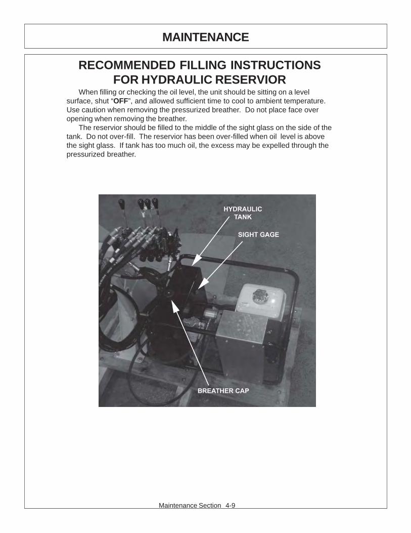
RECOMMENDED FILLING INSTRUCTIONSFOR HYDRAULIC RESERVIOR
When filling or checking the oil level, the unit should be sitting on a levelsurface, shut “OFF”, and allowed sufficient time to cool to ambient temperature.Use caution when removing the pressurized breather. Do not place face overopening when removing the breather.
The reservior should be filled to the middle of the sight glass on the side of thetank. Do not over-fill. The reservior has been over-filled when oil level is abovethe sight glass. If tank has too much oil, the excess may be expelled through thepressurized breather.

Maintenance Section 4-10
MAINTENANCE
GREASING POINTS ON BOOM AND PIVOTLocate grease zerks on deck pivot assembly, at main / secondary boom joint, and
at main boom / main frame joint. Inject Lithium-Complex Extreme Pressure greaseconforming to NLGI2-ISO 320 specifications until grease begins to protrude from ends.
PIVOT ASSY
BOOM

Maintenance Section 4-11
MAINTENANCE
GREASING BOOM CYLINDER(S) PIVOT POINTSLocate the zerk on the butt end tang of cylinder and on rod end tang. Inject Lithium-
Complex Extreme Pressure grease conforming to NLGI2-ISO 320 specifications untilgrease begins to protrude from ends. This procedure is to be used on the main boomcylinder, secondary boom cylinder, mower pivot cylinders daily or at 8 hour intervals.

Maintenance Section 4-12
MAINTENANCE
DAILY MAINTENANCE SCHEDULE
The following services should be performed daily or every 8 hoursof service, following the detailed maintenance instructions in the operatorsmanual.
______ Pivot points: Inject grease until it appears at ends.
______ Hydraulic fittings: Check for leaks with paper or cardboard. Tighten fittings or replace hoses immediately.
______ Knives: Inspect for missing or damaged knives, change (onlycomplete sets) as needed.
______ Main Frame / Deck: Unless otherwise specified retorque boltsaccording to torque specifications in thissection.
______ Hydraulic Fluid Level: Add, if required, per fluid recommendations.
Service performed by:_______ Date:____/____/____ HourMeter:__________
Maintenance Section** This page may be copied and used as part of the daily maintenance routine.

PARTSSECTION
SICKLE BAR MOWER
Parts Section 5-1

Parts Section 5-2
The following instructions are offered to help eliminate needless delay and error inprocessing purchase orders for the equipment in this manual.
1. The Parts Section is prepared in logical sequence and grouping of parts thatbelong to the basic machine featured in this manual. Part Numbers andDescriptions are given to help locate the parts and quantities required.
2. The Purchase Order must indicate the Name and Address of the person ororganization ordering the parts, who should be charged, and if possible, the serialnumber of the machine for which the parts are being ordered.
3. The purchase order must clearly list the quantity of each part, the completeand correct part number, and the basic name of the part.
4. The manufacturer reserves the right to substitute parts where applicable.
5. Some parts may be unlisted items which are special production items notnormally stocked and are subject to special handling. Request a quotation for suchparts before sending a purchase order.
6. The manufacturer reserves the right to change prices without prior notice.
NOTE: When ordering replacement decals, refer to the part numbers anddescriptions listed in the safety section in the front of this manual.
For maximum safety and to guarantee optimum product reliability,always use genuine Tiger replacement parts. The use of inferiorreplacement parts may cause premature or catastrophic failurewhich could result in serious injury or death.
Direct any questions regarding parts to:
Tiger Corporation3301 N. Louise Ave.
Sioux Falls, SD 571071-800-843-6849 1-605-336-7900
PARTS ORDERING GUIDE

Parts Section 5-3
PARTS SECTION TABLE OF CONTENTS
SECTION PAGE
BOOM ASSEMBLY 1 5-4
BOOM ASSEMBLY 2 5-6
HYDRAULICS ASSEMBLY 5-8
SICKLE BAR DRIVE ASSEMBLY 5-10
SICKLE BAR KNIFE ASSEMBLY 5-12
VALVE BREAKDOWN 5-14

Parts Section 5-4
SICKLE BAR MOWER - BOOM ASSEMBLY

Parts Section 5-5R 00-00
SICKLE BAR MOWER - BOOM ASSEMBLY
ITEM P/N QTY DESCRIPTION1 06310120 1 MNT,BOOM2 06310121 1 BOOM,MAIN3 06310122 1 BOOM,SEC4 06310123 1 LINKAGE,15 06310124 1 LINKAGE,26 06770046 3 CYLINDER ASSEMBLY,TAPPED7 06520431 1 SICKLE BAR,ESM8 06520420 1 KIT,ENGINE9 52107-4 3 PIN YDP, 1.00 X 5.25"10 40332 1 PIN SHAFT11 33503 4 PIN,1X5.75",W/HOLE12 06360002 2 PIN,1.00x5.87,W.25HOLE,CAP13 6T3207 5 GREASE ZERK,1/4"14 21734 6 CAPSCREW, 1/2 x 2-1/4,NC15 21727 6 NYLOCK NUT, 1/216 22018 12 FLATWASHER,1/2",WIDE17 21577 3 HEX NUT,NYLOCK,5/16" NC18 21627 5 NYLOCK NUT,3/8",NC19 21585 3 CAPSCREW, 5/16 x 2 1/4,NC20 21635 5 CAPSCREW,3/8x2 1/4,NC21 21688 1 CAPSCREW,7/16" X 3-1/4" NC22 33880 1 FLATWASHER,3/4",GR 8,SAE23 22533 1 COTTER PIN,3/16 X 224 06537021 2 ROLL PIN, 5MM x 50MM25 27508 4 CAPSCREW,8MMx20MM(1.25 PITCH)26 21677 1 HEX NUT,NYLOCK,7/16" NC27 6T3211 6 GREASE ZERK, 1/8”28 06520432 1 MOTOR

Parts Section 5-6
SICKLE BAR MOWER - BOOM ASSEMBLY 2

Parts Section 5-7
SICKLE BAR MOWER - BOOM ASSEMBLY 2
ITEM P/N QTY DESCRIPTION1 06310120 1 MNT,BOOM2 06310121 1 BOOM,MAIN3 06310122 1 BOOM,SEC4 06770046 3 CYLINDER ASSEMBLY,TAPPED5 06505117 4 CLAMP KIT,HOSE,.63x2,.5x6,2PST6 06505119 1 CLAMP KIT,HOSE,.63x2,2PST7 06505120 2 CLAMP KIT,HOSE,.63x2,.5x3,2PST8 06505121 1 CLAMP KIT,HOSE,.63x4,.5x6,3PST9 32901 4 ADAPTER,3/8MORx3/8MJ10 06503146 2 ADAPTER,3/8MORx3/8MJ,CHCK RES11 06503137 1 KIT,FLANGE,30mm12 06503138 1 KIT,FLANGE,40mm13 06503144 2 ELBOW,3/8BSPPx3/8MJ

Parts Section 5-8
SICKLE BAR MOWER - HYDRAULICS ASSEMBLY

Parts Section 5-9
SICKLE BAR MOWER - HYDRAULICS ASSEMBLY
ITEM P/N QTY. DESCRIPTION1 06310120 1 MNT,BOOM,WEEDOO2 REF 1 KIT,ENGINE,WEEDOO3 6T3207 3 GREASE ZERK,1/4"4 06550056 1 DECAL,CNTRL,WEEDOO5 21530 3 CAPSCREW,1/4" X 1" NC6 21527 5 HEX NUT,NYLOCK,1/4" NC7 21534 2 CAPSCREW,1/4 x 2 NC8 21635 2 CAPSCREW,3/8x2 1/4,NC9 21627 2 NYLOCK NUT,3/8",NC10 06505121 1 CLAMP KIT,HOSE,.63x4,.5x6,2PST11 06502118 1 VLV,4SP,BRAND,WEEDOO12 06502122 1 FLW CNTRL,WEEDOO13 06340034 1 VLV MNT,WEEDOO14 32901 15 ADAPTER,3/8 MOR X 3/8 MJ15 32902 1 ELBOW,3/8MORx3/8MJ16 33399 1 ELBOW,1/2MPX3/8MJ 9017 06503048 1 RUN TEE,3/8MJ x 3/8FJX x 3/8MJ18 06503145 1 ADAPTER,3/16MORx1/4MJ19 06520452 1 SUCTION STRAINER20 33382 1 ELBOW,1/2 MJx1/2 ORB21 06500505 2 HOSE,#6x230(6FJXx6FJX90)22 33561 2 HOSE,#4x10⁵(6FJX90x6FJX)23 06500061 2 HOSE,#4x166(6FJXx6FJX90)24 06500164 2 HOSE,#4x216(6FJX90x6FJX)25 06500506 1 HOSE,#6x101(6FJX90x6FJX)26 33411 1 HOSE,#4x24(6FJX90x6FJX)27 06500434 1 HOSE,#4x18(6FJXx6FJX90)28 06500507 1 HOSE,#6x97(6FJXx6FJX)29 06500508 1 HOSE,#4x22(4FJX90x6FJX)30 06500531 1 HOSE,#8x18(8FJXx12MP)31 06520451 1 CAP,BREATHER32 06520450 1 ELEMENT,FILTER33 06520442 1 PUMP34 06520440 1 ENGINE35 06520445 1 SIGHT GLASS36 06505128 1 TANK,WEEDOO

Parts Section 5-10
SICKLE BAR MOWER - DRIVE ASSEMBLY

Parts Section 5-11
SICKLE BAR MOWER - DRIVE ASSEMBLY
ITEM PN DESCRIPTION1 273 0060 CARRIER
280 0740 SUPPORT2 280 0730 ARTICULATION3 285 0150 FLANGE4 590 0520 GROOVED BALL BEARING,6305 2RS5 300 5050 SHAFT6 555 1250 SHIM RING,SS,50x62x37 590 2190 INNER RING,LR,25x30x20,58 590 1440 NEEDLE BUSHING,H3020 2RS9 566 0140 RETAINING RING,50x2,010 323 1150 COUPLER11 557 0010 GREASE NIPPLE
13 560 2650 HEXAGON BOLT M10x3514 565 0120 LOCKWASHER A1015 537 0410 HEXAGON NUT16 281 1640 CRANK DISK
280 1160 CONNECTING ROD CPLT17 280 1140 CONNECTING ROD18 502 0120 BUSHING GFM19 324 0590 BUSHING20 590 0450 GROOVED BALL BEARING21 566 0210 RETAINING RING
22 367 0500 WASHER23 560 3130 HEXAGON BOLT M16x4524 565 0170 LOCKWASHER A1625 324 1650 CLUTCH BUSHING27 562 0410 SCREW WITH RIPP FLANGE M8x1228 276 0120 SAFETY COVER30 363 1030 SHIM 0.2MM31 363 1040 SHIM 0.5MM32 332 1210 GUIDE PLATE FRONT33 555 0200 WASHER,10.534 565 0120 SPRING WASHER,A1035 560 2630 HEXAGON BOLT,10x25

Parts Section 5-12
SICKLE BAR MOWER - KNIFE ASSEMBLY

Parts Section 5-13
SICKLE BAR MOWER - KNIFE ASSEMBLY
ITEM PN DESCRIPTION260 1700 MOWER KNIFE
1 544 0111 CTSK RIVET 5x122 544 0151 CTSK RIVET 5x175 344 1331 KNIFE SECTION6 344 1311 DOUBLE KNIFE SECTION7 344 1321 DOUBLE KNIFE SECTION10 355 1350 KNIFE BACK12 304 0730 BAR BACK15 321 0021 BAR SECTION16 321 1061 DOUBLE BAR SECTION18 267 0860 KNIFE HOLDER19 560 2230 HEXAGON BOLT20 537 0610 LOCKNUT21 537 0420 HEXAGON NUT M823 332 0280 GUIDE PIECE24 559 0130 ROUND HEAD SCREW M8x4526 559 0030 ROUND HEAD SCREW M8x2327 555 0810 CONICAL SPRING WASHER,8
247 2590 KNIFE HEAD28 247 2580 KNIFE HEAD29 332 1240 GUIDE PLATE30 332 1230 GUIDE PLATE31 544 0601 CTSK RIVET 8 x 25
33 324 0780 SPACER BUSH34 565 0200 SPRING WASHER C12,535 560 0910 HEXAGON BOLT,M12x5536 537 0810 LOCKNUT,NM1237 562 0410 SCREW WITH RIPP FLANGE M8x12
137 0100 DRIVE ASSEMBLY - PREVIOUS PAGE39 560 0610 HEXAGON BOLT,M10x4040 560 0600 HEXAGON BOLT,M10x5042 321 2010 CUTTING PLATE44 332 1220 GUIDE PLATE REAR45 363 1030 SHIM 0.2MM46 363 1040 SHIM 0.5MM47 363 1320 SHIM 3.0MM48 555 0200 WASHER 10.549 565 0120 SPRING WASHER A1050 537 0410 HEXAGON NUT M10
925 0120 PVC PROTECTION

Parts Section 5-14
SICKLE BAR MOWER - VALVE BREAKDOWN

Parts Section 5-15
SICKLE BAR MOWER - VALVE BREAKDOWN
ITEM P/N QTY. DESCRIPTION- 06502118 REF VALVE,SICKLE BAR MOWER1 20PG1B25 1 INLET2 REF 1 DRAIN BLOCK3 20BFST4SB 3 WORK SECTION,SPRING CENTERED4 REF 1 SERIES BLOCK5 20BFMICB25 1 MIDINLET6 20BFO42DB 1 WORK SECTION,DETENT7 20TG1 1 OUTLET8 20TR6 1 TIE-ROD KIT9 20HB 4 HANDLE10 SUB-20B2 2 RELIEF11 20BK - SEAL KIT - BETWEEN SECTIONS12 20CK - SEAL KIT - INLET SECTION13 20AK-S - SEAL KIT - WORK SECTION,SPRING CENTERED14 20AK - SEAL KIT - WORK SECTION,DETENT

Parts Section 5-16
NOTES

WARRANTYSECTION
Warranty Section 7-1

.

WARRANTY INFORMATION
Tiger Corporation, 3301 N. Louise, Sioux Falls, South Dakota, warrants to theoriginal Retail Customer, the new Tiger equipment is free of defects in material andworkmanship. Any part of equipment that in Tiger’s judgement, show evidence ofsuch defects will be repaired or replaced without charge, provided that the failure ofpart(s) shall have occurred within twelve (12) months from the date of delivery ofsaid equipment to the Retail Customer. Expendable components such as knives,oil, chain sprockets, skid shoes, knife mounting disks and the like are excluded butnot limited to this warranty.
The Retail Customer must pay the transportation cost to and from the TigerDealer’s service shop for warranty service. Warranty service will be performed bythe Tiger Dealer from whom the equipment was purchased, during service shopregularly scheduled days and hours of operation.
All Tiger obligation under this warranty shall be terminated if the equipment ismodified or altered in ways not approved in writing by Tiger, if repair parts other thangenuine Tiger repair parts have been used, or if the equipment has been subject tomisuse, neglect, accident, improper maintenance or improper operation.
Tiger Corporation reserves the right to make improvements in design orchanges in specification at any time without incurring any obligation to owners ofequipment previously sold.
No agent or person has authority to alter, add to or waive the above warrantieswhich are agreed to be in the only warranties, representations or promises,expressed or implied, as to the quality or performance of the products covered andwhich do not include any implied warranty of merchantability or fitness. In no eventwill Tiger be liable for incidental or consequential damages or injuries, including, butnot limited to, loss of profits, rental or substitute equipment or other commercialloss.
THERE ARE NO WARRANTIES WHICH EXTENDBEYOND THOSE EXPRESSED HEREIN.
It is the Purchasers obligation to sign the warranty registration form AFTER he /she has Read and Understands the Operation and Safety Instructions statedwithin this manual.

ONE LAST WORDThis manual cannot possibly cover all of the
potentially hazardous situations you willencounter. By being familiar with the
safety rules, operating and maintenanceinstructions in this manual you can help preventaccidents. The objective of this manual is to
help make you a better operator. Remember,SAFETY IS YOU!
Your safety and the safety of those around youdepends on YOU. Common sense should
play a large role in the operation of this machine.
Since we at Tiger Corporation are constantly striving to improve out products, wereserve the right to change specifications or design at any time.

TO THE OWNER / OPERATOR / DEALER
To keep your implement running efficiently and safely, read your manual thoroughly and followthese directions and the Safety Messages in this manual and on the machine. The table ofcontents clearly identifies each section where you can easily find the information you need.
The Occupational Safety and Health Act (OSHA 1928.51 subpart C) makes the followingminimum requirements for tractor operators.
OWNER REQUIREMENTS:
1. Provide a Roll-Over-Protective Structure that meets the requirements of this Standard; and2. Provide Seatbelts that meet the requirements of this Standard and SAE J3C; and3. Ensure that each employee uses such Seatbelt while the tractor is moving; and4. Ensure that each employee tightens the Seatbelt sufficiently to confine the employee to the
protected area provided by the ROPS.
OPERATOR REQUIREMENTS:
1. Securely fasten seatbelt it the tractor has a ROPS.2. Where possible, avoid operating the tractor near steep ditches, embankments, and holes.3. Reduce speed when turning, crossing slopes, and on rough, slick, or muddy surfaces.4. Stay off slopes too steep for safe operation.5. Watch where you are going – especially at row ends, on roads, and around trees.6. Do Not permit others to ride.7. Operate the tractor smoothly – no jerky turns, starts, or stops.8. Hitch only to the draw-bar and hitch points recommended by the tractor manufacturer.9. When the tractor is stopped, set brakes securely and use park lock, if available

Printed in USA© Tiger Corporation