siare srio s2 - service manual
TRANSCRIPT

DU5051114
( rev.4) 01.06.2005
LUNG VENTILATOR
Sirio S2 / T
SERVICE MANUAL


Sirio S2 / T Service Manual
DU5051114 3 ( 30 ) ( rev.4) 01.06.2005
INDEX
1 INTRODUCTION ............................................................................................................................. 5 1.1 Main characteristics of SIRIO S2/T .......................................................................................... 5 1.2 Operating.................................................................................................................................. 6 1.3 Norms....................................................................................................................................... 6 1.4 Warnings .................................................................................................................................. 7
2 DESCRIPTION OF SIRIO S2/T LUNG VENTILATOR ................................................................... 9 2.1 Front view................................................................................................................................. 9 2.2 Left and right side views......................................................................................................... 10 2.3 Bottom side view .................................................................................................................... 10
3 PREPARATION TO USE .............................................................................................................. 11 3.1 Electric connection ................................................................................................................. 11
3.1.1 External battery supply............................................................................................................... 11 3.1.2 Safety fuses ............................................................................................................................... 11 3.1.3 Connection to other equipments ................................................................................................ 11
3.2 Medical gas connection.......................................................................................................... 11 3.3 Silicone patient circuit connection .......................................................................................... 12
4 HOW TO USE THE SIRIO S2/T LUNG VENTILATOR................................................................. 13 4.1 General................................................................................................................................... 13 4.2 Operating MODES ................................................................................................................. 13
4.2.1 OFF............................................................................................................................................ 13 4.2.2 AUT + AST................................................................................................................................. 13 4.2.3 PSV............................................................................................................................................ 13 4.2.4 CPAP ......................................................................................................................................... 13
4.3 Optional operations ................................................................................................................ 14 4.3.1 Vehicular power supply .............................................................................................................. 14 4.3.2 Internal battery ........................................................................................................................... 14 4.3.3 PEEP ......................................................................................................................................... 14 4.3.4 Variable TRIGGER .................................................................................................................... 14
5 MAINTENANCE ............................................................................................................................ 15 5.1 General................................................................................................................................... 15 5.2 Scheduled Maintenance (performed by the operator) ........................................................... 15
5.2.1 Cleaning of the housing ............................................................................................................. 15 5.2.2 Washing ..................................................................................................................................... 16 5.2.3 Disinfecting by cold immersion................................................................................................... 16
5.3 Spare parts............................................................................................................................. 16 5.4 Special waste materials ......................................................................................................... 16
6 SERVICE ....................................................................................................................................... 17 6.1 Electric and pneumatic calibration ......................................................................................... 17
6.1.1 Electric calibration...................................................................................................................... 17 6.1.2 Pneumatic calibration................................................................................................................. 18
6.2 Testing.................................................................................................................................... 18 7 DRAWINGS ................................................................................................................................... 23
7.1 Electric connections ............................................................................................................... 23 7.2 Pneumatic drawing................................................................................................................. 24 7.3 Electronic boards.................................................................................................................... 25
7.3.1 Main board ................................................................................................................................. 25 7.3.2 Power board............................................................................................................................... 26 7.3.3 Analogic board ........................................................................................................................... 27 7.3.4 Logic board ................................................................................................................................ 28
8 TECHNICAL DATA SHEET .......................................................................................................... 29 8.1 Legend of abbreviations and symbols.................................................................................... 30

Service Manual Sirio S2 / T
( rev.4) 01.06.2005 4 ( 30 ) DU5051114
Warning !!
“SIARE” is used throughout this manual as an abbreviation for:
SIARE HOSPITAL SUPPLIES S.r.l. Via Giulio Pastore, 18 - 40056 Crespellano (BO) - ITALY
Tel.: 051.969802 / Fax: 051.969101
In quality of Manufacturer of the equipment described in the present manual.

Sirio S2 / T Service Manual
DU5051114 5 ( 30 ) ( rev.4) 01.06.2005
1 INTRODUCTION This manual is expressly intended for SIARE qualified personnel or for qualified technical personnel, officially authorized by SIARE to maintain the SIRIO S2/T.
The present manual describes the SIRIO S2/T and its operation principles, by the aid of constructive, electrical and pneumatic drawings.
The SIARE qualified personnel or the qualified technical personnel officially authorized by SIARE, must know the complete content of the present manual, before performing the operations described here below.
The technician authorized by SIARE is equipped with proper tools and spares and he is instructed to operate for products preservation.
! SIARE declines all responsibilities arising from technical intervention performed on the equipment without a formal authorization by SIARE.
A proper and safe use of SIRIO S2/T lung ventilator both for the patient and the operator requires the perfect knowledge of the recommendations and instructions indicated in the present manual.
1.1 Main characteristics of SIRIO S2/T The portable SIRIO S2/T lung ventilator is specially designed to be used in emergency, first-aid, intra-hospital transportation and it is destined to be applied on adults, children and newborns.
The following ventilation modes are featured: • at continuous flow (CPAP);
• automatic ventilation through a time cycled breathing activity synchronized with the patient’s spontaneous activity (AUT+ AST);
• assisted with pressure support (PSV - Pressure Support Ventilation).
Among the default functions the following can be adjusted: • breathing cycle frequency in AUT+AST mode (Fix I:E Ratio 1:1,5);
• delivered minute volume or flow;
• max airway pressure limit in AUT+AST mode;
• pressure support level in PSV;
• oxygen concentration (MIXER 50 or 100%).
SIRIO S2/T measures and displays: • the instant airways pressure;
• the spontaneous patient activity in AUT+ AST and PSV modes;
• an eventual alarm status (LOW PAW/APNEA, GAS SUPPLY, LOW BATT, HIGH PAW/LIMIT, POWER FAILURE).
! The ventilation of critical patients without continuous control must be effected by using an external spirometer having alarms on minute volume.

Service Manual Sirio S2 / T
( rev.4) 01.06.2005 6 ( 30 ) DU5051114
1.2 Operating For a correct and complete operating the equipment must be connected to the medical gas distribution system outlet or to the cylinder outlet.
In order to supply mixtures at 21% O2 the equipment can be connected to medical compressed air. In this case the adjustment of the mixer at 50% and 100% values will not affect the concentration.
SIRIO S2/T has a built-in battery that allows it to operate for at least 6 hours when the battery is fully charged and in good operating order.
An external 12 Vdc battery (from an ambulance, helicopter, etc...) can also be used as a source of power for SIRIO S2/T .
SIRIO S2/T includes an airway pressure gauge for measuring the patient’s airway pressure, a patient’s spontaneous activity sensor and a sensor that activates an alarm for low airway pressure.
It is necessary to check these sensors before using them, in order to avoid incorrect evaluation of the patient’s ventilation. The test procedures are described in chapter 4 of this manual.
The electrical and medical gas system connections should be made as per the procedures described in chapter 4.
1.3 Norms SIRIO S2/T is a lung ventilator manufactured according to the following norms:
CEI 62-5 : 1991 (EN 60601-1) Electromedical Equipment.
Part 1: General Safety Norms
UNI EN 794-3 Particular requirements for emergency and transport ventilators
CEI 62-50 :1993 (EN 60601-1-2) Electromedical Equipment.
Part 1: General Safety Norms.
Part 2: Collateral Norms: Electromagnetic Compatibility –
Recommendations and tests.
CEI 64-4 Electrical Installation in locations used for medical practice.
IEC 601-4 Programmable devices
ISO 5356 (EN 1281) Connectors
Dir. 93/42/CEE
Dir. 89/336/CEE
Medical devices
Electromagnetic compatibility

Sirio S2 / T Service Manual
DU5051114 7 ( 30 ) ( rev.4) 01.06.2005
1.4 Warnings
This symbol means that an important note or information is following.
! This symbol means that a very important remark for the patient’s and operator ‘s safety is following.
In order to grant maximum reliability and to ensure the patient and operator’s safety, SIRIO S2/T was designed and manufactured following warranty standards of quality of the product and its components.
Therefore safety of SIRIO S2/T is warranted only if it is used following the procedures described in the user’s manual.
For safety reasons, it is necessary to perform the scheduled maintenance described in this manual.
Maintenance and replacement of spare parts should be made by personnel authorized by SIARE only and original SIARE spare parts or spare parts checked by SIARE should be used without exceptions.
SIARE is not held liable (Civil Law or Penal Code) in the following situations. 1) If SIRIO S2/T is used not for the aims or in the conditions described in the present manual.
2) For lack or omission of performance of the scheduled maintenance as described in this manual.
3) For maintenance not performed by SIARE authorized.
4) If non-original spare parts or parts not checked by SIARE were used.
5) If connected to devices not in conformity with governmental safety norms for the recommended use.
!
Do not use this equipment near flammable gases. Make an inspection prior to use. Do not connect the equipment to the patient by using conductive antistatic tubes.
Regarding the general safety of the electro-medical equipment, it is important to follow all rules regarding the interaction between the equipment and the patient, the operator and the nearby environment.
In order to ensure proper and safe use of the equipment, it is crucial to follow the instructions and pay attention to the notes furnished in this user’s manual.
In order to use this equipment, it is vital to know all the instructions present in this manual.

Service Manual Sirio S2 / T
( rev.4) 01.06.2005 8 ( 30 ) DU5051114
The equipment must be checked and inspections must be performed by SIARE authorized personnel every 800 operating hours, or in case of limited use of the unit, at least every 6 months. All maintenance performed by SIARE authorized personnel is recorded in the equipment’s maintenance file.
Every repair must be performed by SIARE authorized personnel.
SIARE is not liable for direct or indirect damage to people or things, due to technical assistance by SIARE non-authorized personnel or improper use of the equipment, that is to say a use not described in the user’s or technical manuals.
In order to repair the equipment malfunctioning, defects or broken parts, the operator should contact SIARE or its authorized local service dealer.
It is important, when requesting service, to specify the model and serial number of the equipment.
It is recommended to have a maintenance and assistance contract with a SIARE authorized service dealer, in order to guarantee the scheduled maintenance required to operate the equipment in a safe and correct manner.
Use the recommended accessories only.
The use of other accessories is authorized only by a written authorization from SIARE as per the safety directives in effect.
Operation of the equipment is authorized only in areas which are in conformity with the safety directives in effect.
!
This unit is not approved for use in areas with danger of explosion. This unit cannot be used in the presence of explosive gases. Before connecting the unit with other electrical equipment not described in this manual, check with the manufacturer.

Sirio S2 / T Service Manual
DU5051114 9 ( 30 ) ( rev.4) 01.06.2005
2 DESCRIPTION OF SIRIO S2/T LUNG VENTILATOR
2.1 Front view The SIRIO S2/T lung ventilator is composed of the following parts.
9
3
2
1
7
8
5 4
6
1 PAW AIRWAYS PRESSURE: mechanic airway pressure gauge which displays the instantaneous airway pressure.
2 ALARM RESET: for safety reasons the acoustic alarm silencer operates for 20 seconds, the alarm is enabled again whenever the airway pressure exceeds 8 cmH2O.
This key also allows to silence the POWER FAILURE ALARM. In critical patients, especially when the operator is not present, it is good practice to connect a breathing monitor in order to verify the ventilation from a volumetric point of view also, not just from a pressure point of view.
3 MINUTE VOLUME: it is a control knob permitting to set the liters per minutes to be delivered to the patient. The suggested settings for adult and pediatric patients are marked on the scale.
4 MODES: knob for selection of the following operating modes: OFF, AUT+AST, PSV, CPAP.
5 RATE: this scale is used in the AUT+AST mode.
6 PRESSURE LIMIT: it is a knob that regulates the maximum airway pressure limit.
7 MIXER: option to select between 50% O2 and 50% AIR or 100% O2.(operating only in case of connection to O2)
8 PEEP: knob to set the end tidal positive pressure.
9 Handle for transport and fixing on 30x10 mm bar.
!
Service Manual Sirio S2 / T
( rev.4) 01.06.2005 10 ( 30 ) DU5051114
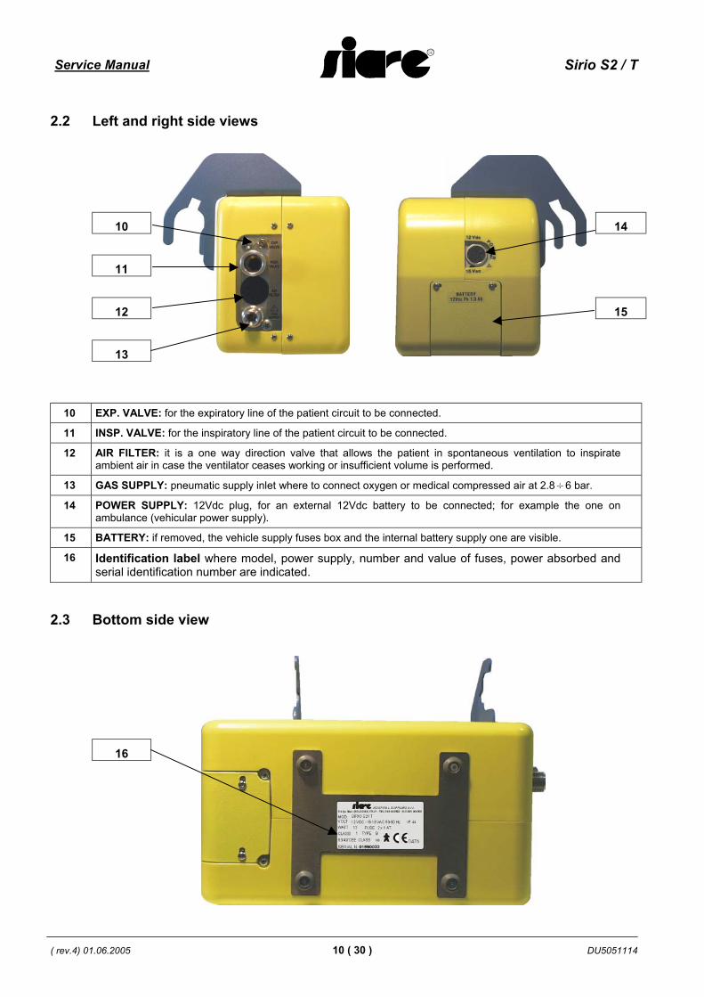
2.2 Left and right side views
10 14
11
12 15
13
10 EXP. VALVE: for the expiratory line of the patient circuit to be connected.
11 INSP. VALVE: for the inspiratory line of the patient circuit to be connected.
12 AIR FILTER: it is a one way direction valve that allows the patient in spontaneous ventilation to inspirate ambient air in case the ventilator ceases working or insufficient volume is performed.
13 GAS SUPPLY: pneumatic supply inlet where to connect oxygen or medical compressed air at 2.8÷6 bar.
14 POWER SUPPLY: 12Vdc plug, for an external 12Vdc battery to be connected; for example the one on ambulance (vehicular power supply).
15 BATTERY: if removed, the vehicle supply fuses box and the internal battery supply one are visible.
16 Identification label where model, power supply, number and value of fuses, power absorbed and serial identification number are indicated.
2.3 Bottom side view
16

Sirio S2 / T Service Manual
DU5051114 11 ( 30 ) ( rev.4) 01.06.2005
3 PREPARATION TO USE
3.1 Electric connection The electrical connection of the unit is a very important phase, because incorrect connections or connection to electrical installations not in conformity to the specifications can be risky for the patient and operator’s safety.
The electrical installation should conform to the local norms for medical installations type "A" (CEI 64.4). Check that the data on the identification label ( power supply, frequency and consumption ) are compatible with the electrical installation.
3.1.1 External battery supply Connect the 12Vdc external battery to the plug [ 14 ] by using our cable.
!
WARNING!! Check polarity. The red cable should be connected to the positive ( + ) pole of the battery.
Turn the MODES selector on the front panel and check that the unit is switched on.
3.1.2 Safety fuses Replace the safety fuse according to the parameters on the label. Fuses with incorrect values can compromise the operation and safety of the unit.
3.1.3 Connection to other equipments If the equipment to be connected is a SIARE unit, all the instructions necessary for the connection can be found in the documentation enclosed. If the equipment to be connected is not a SIARE unit, please contact the manufacturer or a qualified technician for assistance.
This unit conforms to norms IEC 60601-1-2 for electro-magnetic compatibility. It is a good rule to install it together with other devices which are also in conformity to the same norms for a good operation.
3.2 Medical gas connection This unit can be connected to the hospital main gas (O2 or AIR) supply or to an oxygen cylinder.
!
WARNING !! The assembly of the compatible connectors with the hospital main gas supply, as allmaintenance operations and/or the replacement of all medical gas supply tubes shouldbe exclusively performed by highly qualified technicians in order to avoid gasinversions that can kill the patient.
• Insert the connector of the oxygen tube ( 21 ) (included) to the main gas connector [ 13 ] in order to use the main system; the technician has to perform the connection of the inlet (23 not included) compatible with the hospital main medical gas supply to the tube.
• If an oxygen cylinder is used, connect the oxygen connector ( 20 ) to the main supply one [ 13 ], then insert the tube ( 22 ) into the pressure reducer of the cylinder and open the valve.
The medical gas pressure should be 2.8 – 6 bar.

Service Manual Sirio S2 / T
( rev.4) 01.06.2005 12 ( 30 ) DU5051114
NOTE The compressed air should be classified for medical use, and therefore it should not contain oil and it should be filtered.
For installation to other units always check the proper manuals.
3.3 Silicone patient circuit connection
[ 10 ] Expiratory valve control tube connection
[ 11 ] Inspiratory patient circuit connection
[ 24 ] D 15 corrugated tube patient circuit inspiratory line
[ 25 ] Airways pressure reading tube
[ 26 ] Expiratory valve
Sirio S2 / T Service Manual
DU5051114 13 ( 30 ) ( rev.4) 01.06.2005
4 HOW TO USE THE SIRIO S2/T LUNG VENTILATOR
4.1 General The outcome of the preliminary functional test must be positive in order to ensure the proper functioning of SIRIO S2/T.
After the inspection phase, SIRIO S2/T can be connected to the patient by using the patient circuit.
!
ATTENTION !!
To follow the instructions and the warnings, reported in the User’s Manual enclosed with the SIRIO PLUS machine.
4.2 Operating MODES
4.2.1 OFF When the MODE [ 4 ] selector knob is on OFF, the unit is off.
4.2.2 AUT + AST When the MODES [ 4 ] selector is on AUT+AST the ventilator operates as a synchronized (with assisted breaths) time-cycled ventilator. When there are no spontaneous breaths, the ventilator effects an automatic time cycled ventilation.
If the pressure limit knob is set to values higher than the ventilation pressure, the ventilator operates as a volumetric ventilator and the Minute Volume can be set with the relative regulator [ 3 ] .
If the pressure limit knob is set to values lower than the ventilation pressure, the ventilator operates as a time-cycled pressure metric ventilator and the flow can be set with the relative regulator [ 3 ] .
4.2.3 PSV When the MODES [ 4 ] selector is on PSV, the ventilator operates an assisted ventilation with pressure support. In this mode the machine only helps in the breathing work. The value of supplied pressure increases according to the set HIGH PRESSURE LIMIT.
When the HIGH PRESSURE LIMIT is set to ZERO the unit performs only the flow that the patient can generate spontaneously, therefore without pressure support.
When the patient stops breathing, after approx. 20 seconds the ventilator automatically switches in AUT+AST (APNEA BACK-UP) mode.
4.2.4 CPAP With MODES [ 4 ] selector on CPAP the ventilator delivers a continuous flow into the patient circuit. In this way the patient is free to breathe spontaneously into the circuit.
During spontaneous breathing the pressure must oscillate around the set value and must decrease when the patient inspires and increase when he expires. If this oscillation is too extended (more than 30%) it is necessary to set an higher flow, so that the oscillation decreases.

Service Manual Sirio S2 / T
( rev.4) 01.06.2005 14 ( 30 ) DU5051114
4.3 Optional operations
4.3.1 Vehicular power supply SIRIO S2/T can operate with an external 12 Vdc battery, such as the vehicular battery, when connected to a 12Vdc plug located on the side [ 14 ].
4.3.2 Internal battery SIRIO S2/T is equipped with an internal battery that, when fully charged and in proper working condition, guarantees at least 6 hours of autonomy. Its charge level is always checked, therefore when there is about 5 minutes of operating time left, a LOW BATT. alarm is enabled.
SIRIO S2/T incorporates also a system for recharging the battery through the main power supply [ 15 ].
4.3.3 PEEP Turn the PEEP knob [ 8 ] in order to set the end tidal positive pressure which can vary from 0 to 20 cmH20; the relative value is displayed on the bronchomanometer [ 1 ] .
4.3.4 Variable TRIGGER The trigger level, which detects the spontaneous activity of the patient is set by default at –1 cmH20 . The operator can vary the level from –1 to –6 cmH20 anyway by acting as follows:
• switch the ventilator on using the MODES knob [ 4 ] and at the same time keep the ALARM RESET key pressed [ 2 ], as long as led 1 on the alarm section is on;
• then push again the ALARM RESET key [ 2 ], in order to change the level of sensitivity from –1 to –6 cmH20;
• once the value is set, wait for 3 seconds and the level of sensitivity will be maintained till the unit is switched off.
When the ventilator SIRIO S2/T is switched on again, the set value will be the default one, i.e. –1 cmH20.

Sirio S2 / T Service Manual
DU5051114 15 ( 30 ) ( rev.4) 01.06.2005
5 MAINTENANCE
5.1 General
!
WARNING !! To ensure the patient and operator’s safety, SIRIO S2/T has to be checked and inspected every 800 operating hours, or in case of limited use of the unit, at least every 6 months.
These inspections and tests require a perfect knowledge of the equipment and therefore must be performed by highly qualified and specifically trained personnel only who has been formally authorized by SIARE.
The anesthetist or doctor is responsible for the ordinary maintenance of the unit, as described in this chapter.
Instructions about how and how often it is suggested cleaning, disinfecting, sterilizing and replacing parts are indicated in this manual and should be strictly followed in order to avoid damage to the equipment and also endanger the patient and operator’s safety.
The components have been selected after technical and comparative tests in the designing phase of the machine. Furthermore, the same components have been tested during the manufacturing cycle in order to obtain the maximum level of safety and reliability for the operator and patient.
For the above mentioned reasons whenever a part needs to be replaced, it must be an original spare part, which has been checked and tested by SIARE.
The scheduled inspections and maintenance are performed automatically if a maintenance contract is signed with SIARE or with an authorized dealer. For more information, please contact SIARE to have the coordinates of an authorized service dealer in your area.
When you require service, please indicate the serial number of the unit and the problem to SIARE or to your authorized technicians.
SIARE assumes responsibility for all provisions of the law, if the unit is used and maintained as per the instructions in this manual and the technical manual.
The Technical Assistance Report, signed by the authorized SIARE technician, is proof of the completion of the scheduled maintenance.
5.2 Scheduled Maintenance (performed by the operator)
5.2.1 Cleaning of the housing The case of the unit does not require special provisions for its cleaning. It can be done whenever necessary, by using a disposable cloth moistened with regular detergent.
Disinfectants ( i.e. Buraton 10F, diluted as per manufacturer’s instruction with regular detergent) can also be used as needed.
Ensure that no liquid enters into the internal parts of the unit.
The following detergents should not be used as they can damage the unit:
• halogenated compounds;
• strong organic acids;
• oxygenated compounds.

Service Manual Sirio S2 / T
( rev.4) 01.06.2005 16 ( 30 ) DU5051114
5.2.2 Washing Wash the disassembled components with a pH of 4 to 8,5 detergent.
Rinse with running water.
5.2.3 Disinfecting by cold immersion Place the disassembled components in a solution of disinfectant, following its instructions.
Rinse with water (preferably decalcified) and shake well in order to remove any residual water. Let it dry well.
5.3 Spare parts Use only original SIARE spare parts or spare parts checked by SIARE.
In absence of indications, the parts can be replaced upon Physician or Technician’s opinion in case of failure or worm parts.
The scheduled replacement for ordinary maintenance concerns the patient circuit: see codes on the technical data sheet 8 “Standard Accessories” table (replacement every 6 months is highly suggested).
The replacement of 12Vdc battery – 1.3Ah (code: E96512000) is to be effected every 24 months.
5.4 Special waste materials Batteries, accumulators and O2 cells:
• do not put them in the fire, explosion risk;
• do not open them, corrosion danger;
• do not recharge batteries.
The batteries and the accumulators are special waste materials and they must be put in appropriate containers in conformity to local norms for getting rid of such waste materials. For further information contact the competent authorities for the environmental and public health monitoring or municipality section for environmental services.

Sirio S2 / T Service Manual
DU5051114 17 ( 30 ) ( rev.4) 01.06.2005
6 SERVICE This chapter is expressly intended for SIARE qualified personnel or for qualified technical personnel, officially authorized by SIARE to maintain the SIRIO S2/T and it describes the SIRIO S2/T and its operation principles, by the aid of constructive, electrical and pneumatic drawings.
The SIARE qualified personnel or the qualified technical personnel officially authorized by SIARE, must know the complete content of the present manual, before performing the operations described here below.
The technician authorized by SIARE is equipped with proper tools and spares and he is instructed to operate for products preservation.
For electric and pneumatic connections drawing refer to chapter 7.
6.1 Electric and pneumatic calibration
Tools/devices and consumables
• Multimeter
• Manometer –20 +100 cmH2O
• Oscilloscope
• Flow analyzer tester for analog lung ventilator
Perform the following connections
• Make the electric and pneumatic connections relevant to the ventilator to be calibrated.
• Power the circuit and select the AUT mode.
6.1.1 Electric calibration
Necessary tools/devices • Frequency-meter
• Voltmeter
• Compressor
Proceed as described here below (see layout on page 25)
a) Connect the frequency-meter between GND and the 4 pin of U5.
b) Rotate the potentiometer present on the panel at the maximum rate.
c) Regulate the trimmer R2 to read a frequency of around 7850Hz +/- 50Hz.
d) Rotate the potentiometer present on the panel to the minimum rate.
e) Regulate the trimmer R3 to read the frequency of around 620Hz +/- 10Hz.
f) Connect the voltmeter between GND and the 2 pin of U4.
Service Manual Sirio S2 / T
( rev.4) 01.06.2005 18 ( 30 ) DU5051114
g) Rotate the trimmer R30 to read 1 Volt on device.
h) Apply 20 cmH2O to pressure transducer.
i) Rotate the trimmer R40 to read 2,4 Volts on device
l) Take off pressure from transducer and repeat the points g, h, i, j until it is no more necessary to intervene on trimmers.
m) Apply 30 cmH2O to pressure transducer and verify that the device displays around 3,1 Volts .
6.1.2 Pneumatic calibration 1. Connect the compressed air source at 4 bar.
2. Completely open FR1 (Minute Volume).
3. Position the mixer on 50%.
4. Connect the Flow Analyzer unit to the inspiratory connector.
5. Activate CPAP mode.
6. Calibrate the PR1 pressure regulator until obtaining a flow of 40.5 l/min.
7. Verify all FR1 regulator scale, eventually adjust the indicator position.
8. Open the FR2 regulator (Pressure Limit) at cmH2O.
9. Always in CPAP mode connect the lung simulator and close FR6 until obtaining 20 cmH2O on simulator.
10. Verify all the FR2 regulator scale, eventually adjust the indicator position.
11. Regulate FR5 at 20 l/min (Flow Analyzer Tester) with the mixer on100%.
12. Verify all the FR7 regulator scale, eventually adjust the indicator position.
13. Regulate FR5 at 40 l/min (Flow Analyzer Tester) with the mixer on100%.
6.2 Testing
Perform the following connections • Connect the electric power cable to the equipment and to the main power supply.
• Connect the compressed air at 3,5 bar to O2 inlet.
• Connect the patient circuit of 120 cm to the equipment and patient simulator.
1. Verify the external aspect Verify if the equipment shows damages, bruises (electric cable and pneumatic circuits) and broken parts or any other kind of defect concerning each external component of the unit.
Verify if all the fixing nuts are correctly positioned and tightened (in particular in case of use with other machines) and in general, if there are situations which could compromise the correct safe operation of the SIRIO S2/T in order to preserve ventilator integrity.
2. Verify the label presence Check that the identification label with data relevant to predisposed power supply for the equipment, is present.

Sirio S2 / T Service Manual
DU5051114 19 ( 30 ) ( rev.4) 01.06.2005
3. Verify the operative mode: AUT+AST Select the AUT+AST operative mode with the operative modes selector.
Set the following parameters:
- Rate = 20 BPM
- High Press limit = 50 cmH2O
- Minute volume = 9 LPM
Check that the Airways pressure manometer indicates a value between 15 cm H2O and 25 cm H2O.
At the end of expiratory phase generate a depression in the patient circuit by pull out the patient simulator bellows.
Verify that the inspiration leds become red and that the inspiration act is generated.
4. Verify the operative mode: PSV
Select the PSV operative mode by pressing the corresponding button on the front pane.
Set the following parameters:
- Rate = 15 BPM
- High Press limit = 20 cmH2O
- Minute volume = 9 LPM
Generate a depression in patient circuit by pulling out the patient simulator bellow.
Verify that the inspiration leds become red and an inspiratory act is generated so to reach the pressure level of 20±2 cmH2O.
5. Verify the operative mode: PEEP Select the AUT+AST operative mode with the operative modes selector.
Set the following parameters:
- Rate = 15 BPM
- High Press limit = 20 cmH2O
- Minute volume = 9 LPM
- PEEP = 20 cmH2O
Verify that the airways pressure manometer indicates between 35 cm H2O and 45 cmH2O as pressure peak and 20±2 cmH2O as end expiration level.
6. Verify the operative mode: CPAP
Select the CPAP operative mode with operative mode selector.
Set the following parameters:
- High Press limit = 10 cmH2O
Verify that the airway pressure gauge indicates 10±1 cmH2O.
- High Press limit = 20 cmH2O
Verify that the airway pressure gauge indicates 20±2 cmH2O.

Service Manual Sirio S2 / T
( rev.4) 01.06.2005 20 ( 30 ) DU5051114
7. Verify the RATE
Connect the patient circuit to the HIGH FLOW range inlet of flow analyzer unit.
Set the following parameters:
- Operative mode: AUT+AST
- High Press limit = 50 cmH2O
- Minute volume = 9 LPM
Verify that the following setted frequencies (RATE) are within the corresponding acceptance limits read on flow analyzer unit.
Setted Rate Lower acceptance limit
(values read on flow analyzer unit) Upper acceptance limit
(values read on flow analyzer unit)
10 9 11
15 13.5 16.5
40 36 44
70 63 77
8. Verification the oxygen mixer !
Connect the O2.
Set the following parameters:
- Operative mode: AUT+AST
- Rate =15
- High Press limit = 50 cmH2O
- Minute volume = 9 LPM
Set the following O2 conc. values and verify that the value read on referring oxymeter is within the corresponding acceptance limits.
Setted O2 conc. O2 conc. Lower acceptance limit O2 conc. Upper acceptance limit
50 45 55
100 90 110
9. Verify the power supply failure (power supply failure alarm) Set the AUT operative mode AUT+AST.
Disconnect the electric power supply.
Verify that:
- ON LINE led switch-off and that ON BATT leds switch-on;
- the ventilator continues working;
When the battery is low the red led lights-on with consequent not resettable acoustic alarm indicating a 5 minutes operation left.

Sirio S2 / T Service Manual
DU5051114 21 ( 30 ) ( rev.4) 01.06.2005
10. Verify the bronchomanometer !
Connect the patient circuit by a T to patient simulator and to inlet of flow analyzer unit ( with PEAK option ).
Set the following parameters:
- Operative mode = AUT+AST
- Rate = 15
Act on Volume Minute knob so to display on ventilator manometer the following peak pressure and verify that the values displayed on flow analyzer unit are within in corresponding acceptance limits.
Setted pressure Lower acceptance limit
(read on flow analyzer unit) Upper acceptance limit
(read on flow analyzer unit)
20 18 22
10 9 11
11. Verify leakages absence !
Leakage test from valves group to the patient (low pressure circuit leakage)
Connect the patient circuit to a patient simulator.
Set the following parameters:
- Operative mode = AUT+AST (or PCV or PSV in Apnoea BACK-UP).
- RATE = 5.
Verify that on ventilator and patient simulator manometer display remains displayed a pressure of 20 cmH2O ± 2 cmH2O for all setted time (10 seconds).
12. Verify the low pressure/apnoea alarm !
Switch-on the ventilator in AUT+AST mode.
Regulate the Minute Volume so that the displayed pressure on the manometer of the patient simulator and ventilator is over 10 cmH2O.
Reduce the Minute Volume so that the pressure decrease to 9 cmH2O.
Verify that within 30 secs the alarm sounds and that the APNOEA led lights-on (on front panel).
Disconnect the patient circuit from the simulator.
Verify that within 30 secs the alarm sounds and APNEA led lights-on.

Service Manual Sirio S2 / T
( rev.4) 01.06.2005 22 ( 30 ) DU5051114
13. Verify the high pressure alarm !
Set the following parameters:
- Operative mode: AUT+AST.
- Minute Volume = 9 LPM.
- Rate = 10 bpm.
Set high pressure alarm at maximum.
Obstruct the Y connector of patient circuit and verify that an high pressure acoustic alarm sounds and that the max. displayed pressure on ventilator manometer do not reach 50 cmH2O (max. mechanic limit).
14. Verify the gas supply alarm
Set the following parameters:
- Operative mode: IPPV (or AUT+AST).
Connect the patient circuit to the simulator.
Close the pneumatic supply.
Verify that an alarm sounds, and that the corresponding led lights-on.
15. Verify the functionality
Select the AUT+AST operative mode.
Connect the patient circuit to High flow range inlet of flow analyzer unit.
Set the following Minute Volume values and for each of them its corresponding value of RATE as per table.
Verify that the displayed Tidal Volume values on flow analyzer unit are within the corresponding acceptance limits (see table).
MINUTE VOLUME SETTING (Liters)
RATE SETTING (BPM)
ACCEPTANCE MIN.LIMIT (Liters)
MAX ACCEPTANCE LIMITS (Liters)
5 20 0.225 0.275
9 20 0.41 0.50
11 20 0.50 0.60
15 20 0.675 0.825

Sirio S2 / T Service Manual
DU5051114 23 ( 30 ) ( rev.4) 01.06.2005
7 DRAWINGS
7.1 Electric connections
INLET PRESSURE
SENSOR
ELECTROVALVE
BOARD FOR BACKPANEL
SWITCH Yellow-green cable to connectto earth (DEVICE HOUSING)
CONNECTOR FOR
EXTERNAL POWER SUPPLY
RED
BLAC
K
BLAC
K
BLU
E
BLU
E R
ED
WHITE RED BLACK
RED
O
RAN
GE
WH
ITE YELLO
W
VIOLET
BLAC
K
EMERGENCY BATTERY
MAIN BOARD
CONNECTOR FOR FLAT
CABLE

Service Manual Sirio S2 / T
( rev.4) 01.06.2005 24 ( 30 ) DU5051114
7.2 Pneumatic drawing

Sirio S2 / T Service Manual
DU5051114 25 ( 30 ) ( rev.4) 01.06.2005
7.3 Electronic boards
7.3.1 Main board

Service Manual Sirio S2 / T
( rev.4) 01.06.2005 26 ( 30 ) DU5051114
7.3.2 Power board

Sirio S2 / T Service Manual
DU5051114 27 ( 30 ) ( rev.4) 01.06.2005
7.3.3 Analogic board

Service Manual Sirio S2 / T
( rev.4) 01.06.2005 28 ( 30 ) DU5051114
7.3.4 Logic board
Sirio S2 / T Service Manual
DU5051114 29 ( 30 ) ( rev.4) 01.06.2005
8 TECHNICAL DATA SHEET
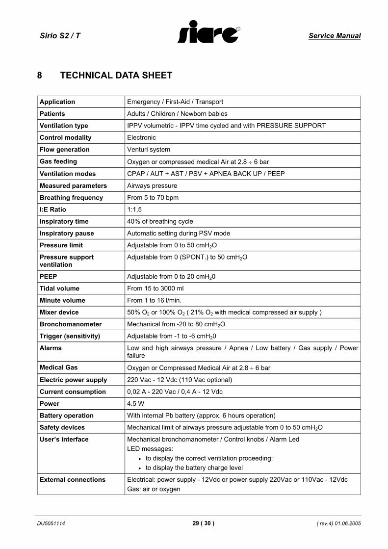
Application Emergency / First-Aid / Transport
Patients Adults / Children / Newborn babies
Ventilation type IPPV volumetric - IPPV time cycled and with PRESSURE SUPPORT
Control modality Electronic
Flow generation Venturi system
Gas feeding Oxygen or compressed medical Air at 2.8 ÷ 6 bar
Ventilation modes CPAP / AUT + AST / PSV + APNEA BACK UP / PEEP
Measured parameters Airways pressure
Breathing frequency From 5 to 70 bpm
I:E Ratio 1:1,5
Inspiratory time 40% of breathing cycle
Inspiratory pause Automatic setting during PSV mode
Pressure limit Adjustable from 0 to 50 cmH2O
Pressure support ventilation
Adjustable from 0 (SPONT.) to 50 cmH2O
PEEP Adjustable from 0 to 20 cmH20
Tidal volume From 15 to 3000 ml
Minute volume From 1 to 16 l/min.
Mixer device 50% O2 or 100% O2 ( 21% O2 with medical compressed air supply )
Bronchomanometer Mechanical from -20 to 80 cmH2O
Trigger (sensitivity) Adjustable from -1 to -6 cmH20
Alarms Low and high airways pressure / Apnea / Low battery / Gas supply / Power failure
Medical Gas Oxygen or Compressed Medical Air at 2.8 ÷ 6 bar
Electric power supply 220 Vac - 12 Vdc (110 Vac optional)
Current consumption 0,02 A - 220 Vac / 0,4 A - 12 Vdc
Power 4.5 W
Battery operation With internal Pb battery (approx. 6 hours operation)
Safety devices Mechanical limit of airways pressure adjustable from 0 to 50 cmH2O
User’s interface Mechanical bronchomanometer / Control knobs / Alarm Led LED messages:
• to display the correct ventilation proceeding; • to display the battery charge level
External connections Electrical: power supply - 12Vdc or power supply 220Vac or 110Vac - 12Vdc Gas: air or oxygen

Service Manual Sirio S2 / T
( rev.4) 01.06.2005 30 ( 30 ) DU5051114
Dimensions 23 x 13 x 15 cm ( W x D x H )
Weight 3.5 Kg
Standard accessories (supplied)
- Power supply cable 12 Vdc (code G30147100) - Silicone patient circuit with expiratory valve (code 102631/SLU) - Disposable patient circuit in PVC with expiratory valve (code A36.049001) - Feeder 220 Vac - 12Vdc (code G30146100) - O2 tube (code G60005100) - User’s manual
Conformity to Norms Internationals Nationals International
Generals IEC 601-1 CEI 62-5
Lung Ventilators for Emergency and Transport
UNI EN 794-3
Medical devices D.93/42/CEE
Electromagnetic Compatibility (EMC)
IEC 601-1-2 : 1993 CEI 62-50 Dir. 89/336
Electric equipment in medical environments CEI 64-4
Programmable devices IEC 601-1-4
Anaesthesia and resuscitation machine – Tapered connections
EN1281-1
ISO 5356
Dir. 93/42 Class and type Class IIb
CEI Class and type Class S.E.I. Type B
Environmental conditions Temperature from 10 to 40°C.
Relative humidity from 10 to 90% non-condensing.
Atmospheric pressure from 70 to 110 kPa.
8.1 Legend of abbreviations and symbols
Abbreviation Description PAW Airway pressure APNEA ALARM Apnea alarm RATE Set breathing rate MINUTE VOLUME Minute volume LOW PAW ALARM Low airway pressure alarm GAS SUPPLY ALARM Lack of gas supply alarm from pneumatic installation LOW BATT ALARM Low battery level alarm BATT LEVEL Battery level