short sisal fibre reinforced - semantic scholar€¦ · 102 short sisal fibre reinforced...
TRANSCRIPT

Chapter
3
MECHANICAL PROPERTIES OF SHORT SISAL FIBRE-POLYSTYRENE
COMPOSITES
Abstract
Short sisal fibre reinforced polystyrene composites were prepared by
solution mixing technique. The influence of fibre length, fibre content
and fibre orientation on the mechanical properties such as tensile
strength, Young’s modulus, elongation at break, flexural properties and
impact properties of the composites were evaluated. The tensile strength
of the composites showed an initial reduction at 10% fibre loading
followed by an increase at 20% fibre loading. However, at higher
loading the properties levelled off. The tensile properties were found to
be almost independent of the fibre length although the ultimate tensile
strength shows marginal improvements at 10mm fibre length. The effect
of fibre loading, fibre length and fibre orientation on the impact energy
and flexural properties of the composites were also studied.
Part of the results discussed in this chapter have been (a) published in
Journal of Applied Polymer Science, 60, 1483, 1996 and (b) submitted for
publication in Journal of Applied Polymer Science.
3.1 Introduction
Several cellulosic products and wastes such as shell flour, wood flour and pulp
have been used as fillers in thermoplastics primarily to achieve cost savings1. The
use of cellulosic fillers of fibrous nature has been of greater interest, as they
would give composites with improved mechanical properties compared to those
containing non-fibrous fillers. The performance of short fibre reinforced
composites depends on factors like aspect ratio, orientation of fibres, and fibre
matrix adhesion2. In the case of fibre reinforced composites there exists a critical
aspect ratio at which the mechanical properties are maximised. Fibre orientation
has a significant influence on the mechanical properties of the composite in that
the stress value is maximum along the axis of orientation of the fibre. The
processing conditions also influence the properties of the composites due to the
chance for fibre breakage during the processing. The ultimate properties of the
composites depend on the extent of stress transfer from matrix to fibres. The
efficiency of this stress transfer depends on a number of factors such as fibre
concentration, fibre dispersion, orientation of fibre, geometry of the fibre and
fibre- matrix interfacial adhesion. Various researchers 3-6 have studied the tensile
properties of short natural fibre reinforced composites. Pavithran et al. have
reported the impact behaviour of unidirectionally oriented sisal fibre composites7.
Vipulanandan and Mebarkia8 reported on the flexural strength, toughness, and
fracture properties of particle filled, fibre reinforced polyester composites. Jancar
et al.9 studied the effects of deterioration of matrix and matrix fibre interface
caused by moisture, on the flexural properties of unidirectional E-glass fibre

Short Sisal Fibre Reinforced Polystyrene Composites 100
reinforced thermoplastics. Rozman et al.10 used hexamethylene diisocyanate
modified ALCELL lignin as a coupling agent in oil palm empty fruit bunch-
polypropylene composites and obtained a greater flexural strength. Gassan et al.11
studied the effects of interphase formed by a silicone interlayer on the mechanical
properties of natural fibre reinforced poly urethanes and an improvement of about
35% was found. The weak interlayer in this case led to a general improvement of
charpy impact energy depending on interphase thickness.
In this chapter a detailed investigation has been carried out on the effects of fibre
length, fibre loading and fibre orientation on tensile, impact and flexural
properties of short sisal fibre reinforced polystyrene composites. A comparison of
the experimental tensile strength and modulus of the composite with theoretical
models such as modified rule of mixtures, series, Halpin-Tsai and Bowyer-Bader
are also discussed in this chapter.
3.2 Results and discussion
3.2.1 Fibre length distribution
In the case of brittle fibres like glass there is chance for fibre breakage during
mixing and extrusion. However, in the case of sisal fibre, most of the fibres retain
their original length after mixing. This is clear from the number average ( nL )
and weight average ( wL ) fibre lengths of fibres before and after mixing given in
Table 3.1. This can be attributed to the flexible nature of cellulose fibre. This is in
agreement with the works reported by Czarnecki and White12. Table 3.1 also
summarises the poly dispersity index (PDI) values of fibres before mixing and

Mechanical Properties of Short Sisal Fibre - Polystyrene Composites 101
that of fibres extracted from the composites based on 100 fibres. The low values
of wL / nL indicate a narrow fibre length distribution before and after mixing.
Table 3.1 Fibre length distribution of chopped sisal fibre and
fibre in composite
Sample
nL (mm)
wL (mm)
wL / nL
Chopped sisal
fibre
6.02 6.12 1.02
Sisal fibre
extracted from
composite
5.69 5.75 1.01
3.2.2 Tensile properties of sisal fibre-PS composites
(a) Effect of fibre length In the case of fibre-reinforced composites, there exist a critical aspect ratio at
which the mechanical properties of the composites are maximized. The critical
aspect ratio depends on the volume fraction of the fibre and also on the ratio of
the modulus of fibre to the matrix modulus13. At low fibre volume fraction, the
fibres play no major role and the strength of the composite is matrix dominated.
The strength of the composite was found to increase above a critical volume
fraction of the fibre, which in fact depends on the aspect ratio. The critical
volume fraction was found to decrease with increase in aspect ratio. At relatively
low fibre volume fraction, the critical aspect ratio remains almost constant,
which, however shows a sharp decrease at higher fibre loading14. As the fibre

Short Sisal Fibre Reinforced Polystyrene Composites 102
length increases, there is a chance for better orientation, which may also lead to
an improvement in mechanical properties of the composite. In the case of low
density polyethylene/sisal fibre system a critical length of 6mm15 and for
NR/sisal fibre system16 and NR/coir system17 a critical fibre length of 10mm was
reported.
Table 3.2 Tensile properties of PS-Sisal fibre composites as a
function of fibre length (fibre loading 20 wt%)
Fibre length
(mm)
Ultimate
tensile
strength
(MPa)
Young’s
modulus
(MPa)
Elongation
at break
(%)
2 36.18 958 5.6
6 43.2 1000 7.8
10 46.87 1047 8.2
To study the effect of fibre length on the tensile properties of the present system
20% fibre loaded composites with average fibre length of 2,6,and 10mm were
prepared. The tensile properties of the composites (Table 3.2) show no
considerable variation with change in fibre length, although the ultimate tensile
strength showed marginal increase at 10mm fibre length.
(b) Effect of fibre loading and orientation
The tensile properties of highly viscous thermoplastics or rubber materials are
governed by several factors such as dispersion (agglomerate formation), increase
of stress concentration points at fibre ends and entrapped air during mixing
(wetting problem) 18. In the case of polystyrene specimens Murray and Hull19 and

Mechanical Properties of Short Sisal Fibre - Polystyrene Composites 103
Hull20 observed that micro voids and cavities occurred within the crazes at the
fibre ends and coalesced to generate planar cavities and or cracking within the
crazes. The chances for some amount of opened cleavage –type fracture during
the pullout process of fibres were also reported21. The broken ends of fibres
formed during the tensile deformation may induce crazes and cracks in the matrix
and may lead to a decrease in the tensile strength19-20. This phenomenon is more
pronounced in the case of samples where the probabilities of breaking of fibres
are higher. Fig.3.1 shows a typical stress-strain curve of sisal fibre-PS composite
at different fibre loadings.
Fig.3.1 Atypical stress-strain curve of sisal fibre-PS composite
Table 3.3 and Figs. 3.2 to 3.6 show the effect of fibre loading and orientation on
the tensile properties of sisal fibre–polystyrene composites. In the case of
longitudinally oriented composite, a reduction in ultimate tensile strength was
observed at lower fibre loading (Table-3.3 and Fig. 3.2). However, increase in
Short Sisal Fibre Reinforced Polystyrene Composites 104
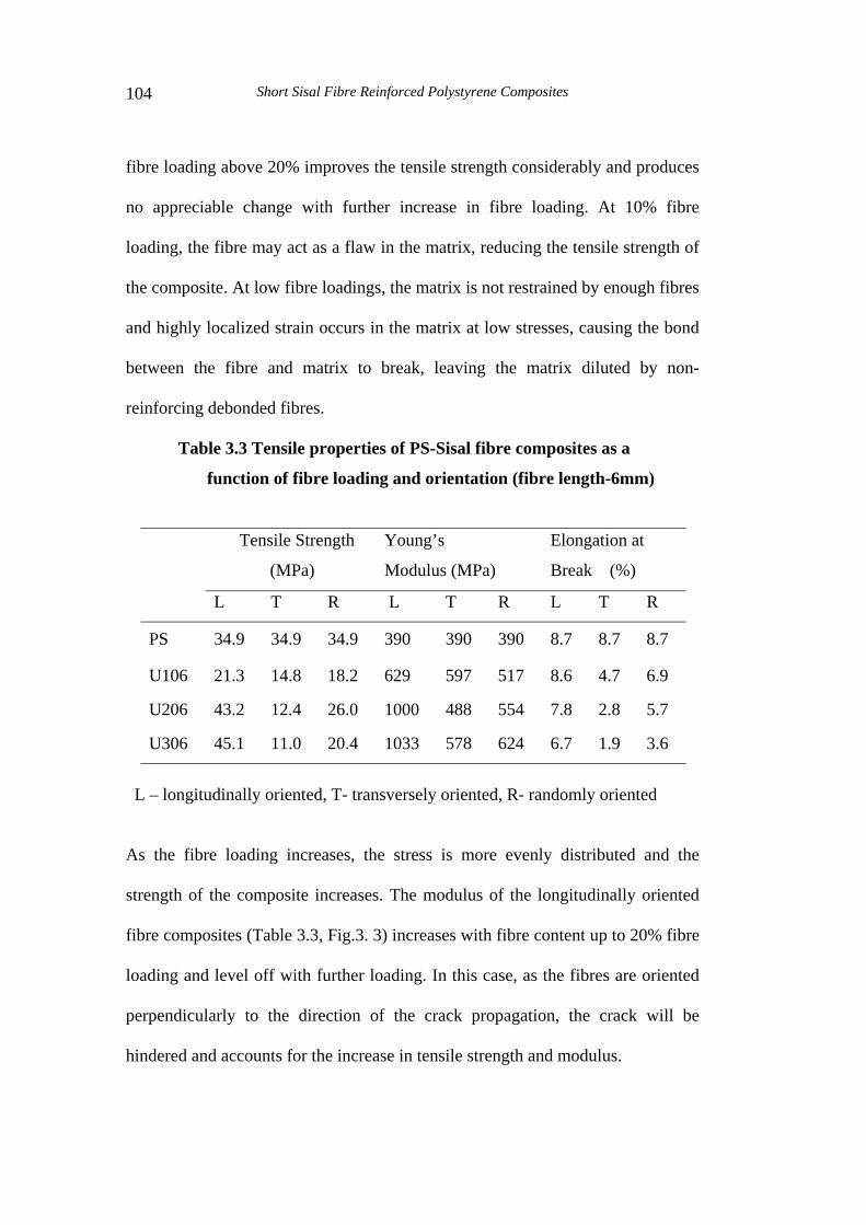
fibre loading above 20% improves the tensile strength considerably and produces
no appreciable change with further increase in fibre loading. At 10% fibre
loading, the fibre may act as a flaw in the matrix, reducing the tensile strength of
the composite. At low fibre loadings, the matrix is not restrained by enough fibres
and highly localized strain occurs in the matrix at low stresses, causing the bond
between the fibre and matrix to break, leaving the matrix diluted by non-
reinforcing debonded fibres.
Table 3.3 Tensile properties of PS-Sisal fibre composites as a
function of fibre loading and orientation (fibre length-6mm)
Tensile Strength
(MPa)
Young’s
Modulus (MPa)
Elongation at
Break (%)
L T R L T R L T R
PS 34.9 34.9 34.9 390 390 390 8.7 8.7 8.7
U106 21.3 14.8 18.2 629 597 517 8.6 4.7 6.9
U206 43.2 12.4 26.0 1000 488 554 7.8 2.8 5.7
U306 45.1 11.0 20.4 1033 578 624 6.7 1.9 3.6
L – longitudinally oriented, T- transversely oriented, R- randomly oriented
As the fibre loading increases, the stress is more evenly distributed and the
strength of the composite increases. The modulus of the longitudinally oriented
fibre composites (Table 3.3, Fig.3. 3) increases with fibre content up to 20% fibre
loading and level off with further loading. In this case, as the fibres are oriented
perpendicularly to the direction of the crack propagation, the crack will be
hindered and accounts for the increase in tensile strength and modulus.

Mechanical Properties of Short Sisal Fibre - Polystyrene Composites 105
0 5 10 15 20 25 30
10
15
20
25
30
35
40
45
50
55
U(R)U(T)
U(L) B C D
Tens
ile s
treng
th (M
Pa)
Fibre content (wt%)
Fig. 3.2 - Variation of tensile strength of PS-sisal fibre composite as a function of fibre loading.
0 5 10 15 20 25 30
400
500
600
700
800
900
1000
U(R)
U(T)U(L) B
C D
Youn
g's
Mod
ulus
(MPa
)
Fibre content (wt %)
Fig. 3.3- Variation of Young’s modulus of PS-sisal fibre composite as a function of fibre loading.

Short Sisal Fibre Reinforced Polystyrene Composites 106
In the case of transversely oriented fibre composites, Fig.-3.2 shows a
considerable deterioration in strength with increase in fibre loading. In this case
the crack propagates in the direction of fibre alignment. The transversely oriented
fibres acts as a barrier and prevents the distribution of stresses throughout the
matrix, and this in turn causes higher concentration of localized stresses. This
explains the reduction in the tensile properties of transversely oriented composite.
In this case, the modulus shows a value higher than that of neat PS and lower
than those of longitudinally oriented composites (Table3.3, Fig.3.3).
0 5 10 15 20 25 30
2
3
4
5
6
7
8
9
U(R)
U(T)
U(L) B C D
Elon
gatio
n at
bre
ak (%
)
Fibre content (wt%)
Fig. 3.4- Variation of elongation at break (%) of PS-sisal fibre composite as a function of fibre loading.
Randomly oriented fibre composite shows tensile strength that lies between those
of longitudinally and transversely oriented fibre composites as expected
(Table3.3, Fig.3.2). At 20 and 30% fibre loading the modulus values also show a

Mechanical Properties of Short Sisal Fibre - Polystyrene Composites 107
similar trend. However, at 10% fibre loading the modulus shows a value less than
that of transversely and longitudinally oriented fibre composite. The reason for
this reduction is not clear.
The data given in Table3.3 and Fig.3.4 also show that in almost all experiments
the ultimate elongation of composites is less than that of unfilled polymer and
decreases with increasing fibre concentration.
3.2.2 Impact properties
The fracture toughness of the composite materials is one of the important
engineering properties. Generally, the impact strength may increase by the
presence of fibres. The presence of filler can impede crack growth due to the
possibility of imposing a greater tendency for plastic deformation in the matrix.
The increase in impact strength is associated with an ability to produce an
increase in the cohesive strength of the matrix or to the change in the distribution
stresses over a larger area. The actual mechanisms for the increase in the impact
strength are numerous and vary depending on the nature of the composites,
temperature and test conditions. During impact testing, the craze formed at a
point of maximum strain grows until it meets another particle or till the stress
concentration at the craze tip falls to zero. Thus, instead of producing large crazes
leading to cracks, when filler is present a large number of micro cracks are
formed. Another possibility that leads to enhance impact resistance is that of
shear yielding in toughened plastics or a combination of crazing and yielding.
In the case of fibre reinforced resins the improvement in impact strength may
also be attributed to the extra energy needed for fibre pullout, debonding or

Short Sisal Fibre Reinforced Polystyrene Composites 108
redistribution of stress, involving creation of new surfaces. Factors affecting the
mode of fracture in fibre reinforced composites are (a) Fibre and matrix strength
(b) Load transfer efficiency (c) Resistance to crack propagation (d) Bond strength
between fibre and matrix and (e) Volume concentration of the fibre and its
geometrical organization22. In the case of short fibre reinforced thermoplastic
composites, the fracture is controlled by fibre pullout. Cracks are found to form at
the fibre ends and misaligned fibres are pulled through the matrix along with
some fibre fracture. In the case of short fibre reinforced composites, fibre length
is also found to be an important parameter in controlling the impact strength, and
the best results are obtained with fibres having critical fibre length. Inter laminar
shear strength also affects the impact strength and increases with increasing shear
strength. Impact strength can be improved by a number of ways23 (a) by using
intrinsically tough matrices, (b) by the application of a soft coating to the fibres
that will act as an interlayer after the composite is fabricated, (c) Utilization of
the energy required to debond the fibres from the matrix and then to pull the
fibres completely out of the matrix and (d) by using a weak interface between
fibre and the matrix.
(a) Effect of fibre loading
Fig 3.5 shows the effect of fibre loading on the impact strength of longitudinally
oriented sisal fibre reinforced PS composites. From this figure, it is clear that at
10% fibre loading the impact strength shows a sharp decrease followed by an
increase at 20 and 30% fibre loading. The maximum impact strength is observed
with 30% fibre loading. At low loading levels, fibres introduce a

Mechanical Properties of Short Sisal Fibre - Polystyrene Composites 109
disproportionately high degree of critical defects to the composite structure,
perhaps in the form of voids or poorly bonded interface regions and reduce the
impact strength. As the fibre loading is increased, reinforcing nature of the
cellulose counterbalances the inclusion of defects and imparts improved
toughness24. The extra energy needed to fibre pullout, debonding and
redistribution of stresses are also responsible for the improvement in impact
strength.
0
5
10
15
20
25
30U306 L
U206 L
U106 L
PS
Impa
ct E
nreg
y (K
J/M
2 )
Fig.3.5- Variation of impact energy of sisal fibre-PS composites as a function of fibre loading
(b) Effect of fibre length and orientation
In the case of short fibre reinforced composites, there exist a critical fibre length
at which the mechanical properties are maximized. In the case of banana fibre

Short Sisal Fibre Reinforced Polystyrene Composites 110
epoxy composites Tobias23 reported that smaller fibre length leads to higher
impact strength at constant fibre loading.
0
5
10
15
20
25
30
35
U2010(T)
U202(T)
U206(L)
U206(T)
PS
Impa
ct E
nerg
y (K
J/m
2 )
Fig.3.6- Variation of impact energy of sisal fibre-PS composites as a function of fibre orientation and length
In the case of oriented system fracture energy is maximum in the direction of
fibre. As mentioned earlier, one of the mechanisms utilized to improve the impact
strength is to utilize the energy to debond the fibres from the matrix and then to
pull the fibres completely out of the matrix. Fibres shorter than Lc will be pulled
out from the matrix, rather than broken, when a crack passes through the
composite sample. This means that for maximum toughness it is desirable to have
a weak interface or use fibres having length L< Lc. Fig.3.6 shows the effect of
fibre length and orientation on the impact strength of PS- sisal composites. It is
observed that the impact energy increases with fibre length up to 6mm followed
Mechanical Properties of Short Sisal Fibre - Polystyrene Composites 111
by a decrease at 10mm fibre length at 20% fibre loading. This is in agreement
with the Cottrell model 25 for unidirectional reinforcement, which includes all the
energy dissipation mechanism like matrix fracture, fibre fracture, debonding and
pullout. As per the model predictions, the impact energy is expected to increase
with increasing fibre length up to fibre lengths equal to the critical fibre length.
At fibre lengths above the critical fibre lengths the impact energy is expected to
decrease again25. This occurrence of a maximum in impact strength can be
attributed to the predicted change in failure mode from fibre pullout at short fibre
lengths (sub critical) to fibre breakage at high fibre length (supercritical) fibre
lengths. This theory is applicable for systems where pullout is the major fracture
mechanism. In thermoplastic composites, no maximum in toughness is observed
but plateau is reached with increasing fibre length26-29. In the present study we
observe a maximum in impact energy at 6mm fibre length followed by a decrease
at 10mm fibre length.
In the case of oriented systems fracture energy is higher for composites with
fibres oriented in the direction of applied force and the highest impact strength is
observed with critical fibre length and poor fibre- matrix bonding. However, for
transverse loading a good bonding is preferred for better impact strength. From
Fig.3.6, it is clear that for sisal fibre- PS composites, the impact energy follows
the order U206 (L)> U206 (T) as expected. It may be noted that in impact testing
U206 (L) corresponds to U206 (T) in tensile testing and vice versa as the force is
applied in different directions in these testing.

Short Sisal Fibre Reinforced Polystyrene Composites 112
3.2.4 Flexural properties
(a) Effect of fibre loading
The loading in flexure in an ideal case causes normal stresses in the direction of
fibres and shear stresses in the plane perpendicular to the loading nose. The
mode of failure of unidirectional composites in flexure is very complex.
Unidirectional composites, when loaded in flexure can fail in tension either
longitudinally or transversely, or in shear in the matrix, interface or fibre30 The
most common modes of failure are transverse splitting, brittle tensile failure, with
fibre pullout, interfacial shear failure, compressive failure due to micro buckling
or localized kinking of fibres and intra-laminar shear failure. When the span /
thickness L/d ratio is less than 25, the failure occurred by fibre buckling localized
in very narrow bands (kink bands). This was reported to be the mechanism of
failure mode in carbon fibre reinforced epoxy. When loaded, either in flexure or
in compression30-32, some relief of local stresses accompanies the micro processes
as the crack propagates from compressive side to the neutral plane. Further
deflection of the beam causes a tensile failure of fibres on the tensile side of the
beam, which leads to catastrophic failure of the specimen. In some cases, some
amounts of inter laminar shear failure, initiated from the kink bands, was
observed on the compressive side8. Constraints imposed on the beam by contact
with the load pin may also inhibit the initiation of bukling in flexural testing.
Fig. 3.7, 3.8 and 3.9 show the effect of fibre loading, fibre length and fibre
orientation on the flexural strength, flexural modulus and flexural strain of sisal
fibre-PS composites.

Mechanical Properties of Short Sisal Fibre - Polystyrene Composites 113
0
20
40
60
80
100
120
U20
6 T
U20
10 L
U20
2 L
U30
6 L
U20
6L
U10
6 L
PS
Flex
ural
stre
ngth
(Mpa
)
Fig. 3.7 – Variation of flexural strength of sisal fibre –PS composite as a function of fibre loading, orientation and length
0
1000
2000
3000
4000
5000
6000
7000
8000
9000
U20
6 T
U20
10 L
U20
2 L
U30
6 L
U20
6 L
U10
6 L
PS
Flex
ural
mod
ulus
(MPa
)
Fig. 3.8– Variation of flexural modulus of sisal fibre –PS composite as a function of fibre loading, orientation and length
Short Sisal Fibre Reinforced Polystyrene Composites 114
0.000
0.005
0.010
0.015
0.020
0.025
0.030
0.035
0.040
0.045
U20
6 T
U20
10 L
U20
2 L
U30
6 L
U20
6 L
U10
6 L
ps
Flex
ural
stra
in
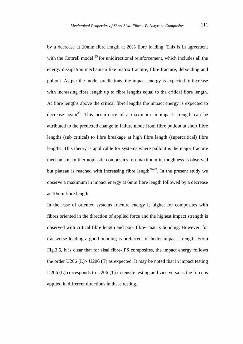
Fig. 3.9 – Variation of flexural strain of sisal fibre –PS composite as a function of fibre loading, orientation and length
From the figures it is clear that the flexural strength and modulus increases with
fibre loading. It is also interesting to note that the addition of 10% fibre reduces
the flexural strain of PS followed by improvement at higher fibre loadings. The
maximum flexural strain was observed at 30% fibre loading (Fig.3.9).
(b) Effect of fibre length and orientation
The effect of fibre length on the flexural strength, modulus and strain is given in
Figs.3.7, 3.8 and 3.9 respectively and shows that all the flexural properties
increases with increase in fibre length and follows the order U210 >U206 >
U202. Ultimate failure is controlled by the strain magnification caused by the
presence of fibres. It is also interesting to note that the flexural strain of 2mm
composites is less than that of neat PS. The effect of fibre orientation on the

Mechanical Properties of Short Sisal Fibre - Polystyrene Composites 115
flexural properties of composites given in Fig.3.7, 3.8 and 3.9 show that the,
when the fibres are oriented perpendicular to the applied force, flexural properties
are maximum.
3.3 Theoretical modelling of tensile properties
The modulus of a material depends primarily on geometry, particle size
distribution and concentration of the filler. In addition to the above factors,
tensile strength depends strongly on the geometry of filler particle and
polymer/filler interaction. In literature a number of models have been developed
to predict the tensile properties of the composites. The suitability of some
important models for predicting the tensile strength and modulus of sisal fibre –
PS composites is examined in below.
(a) Modified rule of mixtures (MROM)
The modified rule of mixtures (MROM) 33 to predict the tensile properties of the
composites can be written as
( ) )1.3........(..........1 ffufmcu VV σσσ +−=
Where,
cuσ is the ultimate strength of the composite, mσ is the matrix strength at the
failure strain of the fibre, fuσ is the ultimate strength of the fibre, is the volume
fraction of fibre and is the effective volume fraction of the fibre. The
effective fibre volume fraction is given in terms of the fibre volume fraction and
the ratio of real contribution as follows
fV
feV
( ) )2.3.......(..........1 PVV ffe −=

Short Sisal Fibre Reinforced Polystyrene Composites 116
Where,
P is the degradation parameter for the effective fibre volume fraction and 0<P<1.
P can be calculated from the micro geometry of the composite component and
depends only on the fibre volume fraction because the micro geometry depends
mainly on fibre volume fraction under identical manufacturing conditions.
P can be calculated from the equation
)3.3......(..........ffu
cu
VP
σσΔ
=
Where,
cuσΔ is the difference between the experimentally measured strength and the
strength predicted from the rule of mixtures.
(b) Parallel and series model
According to these models, Young’s modulus and tensile strength and modulus
of the composite is given by,
Series model
)4.3......(..........mfufm
fmcu VV σσ
σσσ
+=
)5.3......(..........mffm
fmc VEVE
EEE
+=
Where, Ec, Em, and Ef are the Young’s moduli of the composite, matrix and fibre
respectively. cuσ , mσ and fuσ are the ultimate strength of the composite, matrix,

Mechanical Properties of Short Sisal Fibre - Polystyrene Composites 117
and the fibre respectively. In this model the stress was assumed to be uniform in
both matrix and fibre34.
(c) Hirsch model
Hirsch model is a combination of both parallel and series models35. According to
this model the tensile strength and Young’s modulus are calculated using
equations
( ) ( ) )6.3......(..........1mfufm
fumffummcu VV
xVVxσσσσ
σσσ+
−++=
( ) ( ) )7.3......(..........1mffm
fmffmmc VEVE
EExVEVExE
+−++=
Where,
‘x’ is a parameter, which determines the stress transfer between fibre and matrix
and the value of ‘x’ mainly depends on fibre orientation, fibre length and stress
amplification effect at the fibre ends.
(d) Halpin –Tsai model
This model can predict the modulus of the blends and oriented composites and
can be represented by the equation
)8.3......(....................1
1⎟⎟⎠
⎞⎜⎜⎝
⎛
−
+=
f
fmc V
VAEE
η
Where,
)9.3........(..................../
1/AEE
EE
mf
mf
+
−=η and
‘A’ is measure fibre geometry, fibre distribution and fibre loading conditions.

Short Sisal Fibre Reinforced Polystyrene Composites 118
0 5 10 15 20 25 300
20
40
60
80
100
120
140
Series modelMROM model
Bowyer model
Hirsh model
Experimental B C D E G
Tens
ile s
treng
th (M
Pa)
Fibre content (wt %)
Fig.3.10 - Comparison of experimental and theoretical tensile strength values of PS-sisal fibre composites.
0 5 10 15 20 25 300
300
600
900
1200
1500
1800
2100
Series modelBowyer modelHalpin- Tsai modelHirsh modelExperimental B
C D E G
Youn
g's
mod
ulus
(MP
a)
Fibre content (wt%)
Fig.3.11 - Comparison of experimental and theoretical modulus values of PS-sisal fibre composites.

Mechanical Properties of Short Sisal Fibre - Polystyrene Composites 119
(e) Bowyer and Bader model
As discussed in chapter 1, according to this model, the tensile strength of short
fibre reinforced composite is the sum of contributions from sub critical and
supercritical fibres and that from the matrix36. According to this model, the
tensile strength is given by
)10.3........(..........21 fufmmcu VKKV σσσ +=
Where, K1 and K2 are the fibre orientation and fibre length factor respectively.
Depending on the fibre orientations the value of K1 changes. K2, the fibre length
factor is given by, K2 = L- Lc /2L ( for fibres with L>Lc) and, K2 =Lc /2l (for
fibres with L< Lc) . In these equations L is the length of the fibre and Lc is the
critical fibre length.
Theoretical tensile strength values of PS-sisal composites calculated using
different models given in Fig 3.10 shows that the models give tensile strength
values comparable to experimental values except at 10% fibre loading.
Theoretical modulus values calculated using different models given in Fig 3.11
shows that Halpin-Tsai model gives good agreement with experimental values up
to 20% fibre loading. All other models give modulus values much lower than the
experimental values. The deviation from the models could be due to various
factors. The chance for the formation of micro voids between the fibre and matrix
during the preparation of composites greatly influence the tensile properties of
the composites. This factor is not accounted for in any of the models used.
Moreover, in all models used it is assumed that the fibres are cylindrically

Short Sisal Fibre Reinforced Polystyrene Composites 120
shaped. However, the actual shape of the sisal fibre is not perfectly cylindrical
due to surface irregularities.
3.4 References
1. G.R.Lightsey, in Polymer Application of Renewable Resource Materials,
C.E.Carraher, Jr. and L.H.Sperling, Eds., Pleanum Press, New
York,1983,p.193.
2. W.D.Callister.Jr., Materials Science and Engineering, John Wiley and
Sons, Inc., New York, 1985.
3. B.Sing, M.Gupta and A.Verma, Polymer Composites, 17,910,1996.
4. J.K.Kim, S.Lu and Y.W.Mai, J.Mater. Sci., 29,554,1994.
5. A.R.Sanadi, S.V.Prasad and P.K.Rohatgi, J.Mater. Sci., 21,4299,1986.
6. P.R.Hornsby, E.Hinrichsen and K.Tarverdi, J.Mater. Sci., 32,1009,1997.
7. C.Pavithran, P.S. Mukherjee, M.Brahmakumar and A..D.Damodaran,
J. Mater. Sci. Lett., 7, 882, 1987.
8. C.Vipulanandan, S. Mebarkia, J. Appl. Polym. Sci., 50, 1159,1993.
9. J.Jancar, A.T. Dibienedetto, J. Mater. Sci. Mater.Med., 4,562,1993.
10. HD Rozman, KW Tan, RN.Kumar, A.Abubakar, Polym. International,
50,561,2001.
11. J.Gassan, AK Bledzki, Angew. Makro. Chemie., 272,17,1999.
12. L. Czarnecki, and J.L.White, J. Appl.Polym. Sci., 25, 1217,1980.
13. Y.Termonia, J.Mater.Sci., 22, 504, 1987.
14. Y.Termonia, J.Mater.Sci., 25, 4644, 1990.
15. K.Joseph , S.Thomas, C.Pavithran, and M.Brahmakumar, J. Appl. Polym.
Sci., 47, 1731,1993.
16. S.Vargese, B.Kuriakose, S.Thomas and A.T.Koshy, Ind. J. Nat.Rubber
Res., 5(1&2), 18,1992.
Mechanical Properties of Short Sisal Fibre - Polystyrene Composites 121
17. V.G.Geethamma, R.Joseph, and S.Thomas, J.Appl. Polym. Sci., 55,
583,1995.
18. Q.Wang, A.Ait- Kadi and S.Kaliaguine, Polym. Comp., 13,414,1992.
19. J.Murray and D.Hull, Polymer, 10,451,1969.
20. D.Hull in Polymeric Materials, E.Baer,ed., ASM, Ohio, 1975, pp 487-
550.
21. N.S.Choi, and K.Takahashi, Colloid Polym. Sci., 270, 659, 1992.
22. R.P.Sheldon, Composite Polymeric Materials, Applied Science
Publishers, 1982.
23. BC.Tobias, Tensile and impact behavior of natural fibre reinforced
composite polymeric materials in advanced composite materials, In:
T.Chandra, AK. Dhingra eds., The minerals, Metals and Materials
Society, 1993.
24. Gillessebe, N.S.Cetin, C.A.S.Hill and M.Hughes, Appl. Comp. Materials,
7, 341,2000.
25. A.H.Cottrell, Proceedings Royal Society, A282, 2, 1964.
26. J.L.Thomson and M.A.Vlug, Composites Part A, 28A, 277,1997.
27. J.K.Wells and P.W.R Beaumont, J. Material. Sci., 20,1275,1985.
28. J.K.Wells and P.W.R Beaumont, J. Material. Sci., 23,1274,1988.
29. V.B.Gupta, R.K.Mittal and P.K.Sharma, Polymer Composites, 10 (1),
16,1989.
30. T.V. Parry and A.S. wornsky, J. Mater. Sci., 16,439,1981.
31. C.R.Chaplin, ibid, 12, 347,1977.
32. C.R.Weaver and J.G. Williams, ibid, 10,1323, 1975
33. C.Lee and W.H.Wang, J. Mater. Sci., 17,160,1981.
34. L.J. Broutman and R.H.Krock, Modern Composite Materials, Addison
Wesley, Reading, MA, 1967.
35. T.J.Hirsch, J.Am. Com. Inst., 59, 427,1962.
36. W.H.Bowyer and M.G.Bader, J.Mater. Sci., 7,1315,1972.