corrosion resistance of steel fibre reinforced · pdf filecorrosion resistance of steel fibre...
TRANSCRIPT
1 DTU Civil Engineering, Technical University of Denmark
Corrosion resistance of steel fibre reinforced structuresVictor Marcos Meson123, Gregor Fischer11 DTU, Department of Civil Engineering, Lyngby, Denmark2 COWI A/S, Tunnel Department, Lyngby, Denmark3 VIA Building, Energy & Environment, VIA University College, Horsens, Denmark
Workshop Instituto Eduardo Torroja, Madrid12/10/2016
2 DTU Civil Engineering, Technical University of Denmark
Acknowledgements
• Supervision team• DTU: Gregor Fischer, Alexander Michel• COWI: Carola Edvardsen, Anders Solgaard• VIA UC: Torben Lund Skovhus
• Sponsors• DTU, COWI, VIA UC• InnovationsFonden, COWIfonden• VDS (Krampeharex, Arcelor‐Mittal, Bekært), Vejdirektoratet, Mapei
• Others• Students: Jakob Jensen, Oliver Thorpe, Simon Bozick, Viktor Balaz• DTU 3D Imaging centre: Carsten Gundlach
3 DTU Civil Engineering, Technical University of Denmark
Contents
1.Introduction
2.Project description
3.Preliminary results
4.Summary
4 DTU Civil Engineering, Technical University of Denmark
1. IntroductionBackground
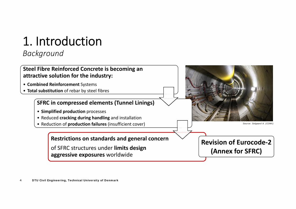
Source: Solgaard A. (COWI)
Steel Fibre Reinforced Concrete is becoming an attractive solution for the industry:• Combined Reinforcement Systems• Total substitution of rebar by steel fibres
SFRC in compressed elements (Tunnel Linings)• Simplified production processes• Reduced cracking during handling and installation• Reduction of production failures (insufficient cover)
Restrictions on standards and general concernof SFRC structures under limits design aggressive exposures worldwide
Revision of Eurocode‐2 (Annex for SFRC)
5 DTU Civil Engineering, Technical University of Denmark
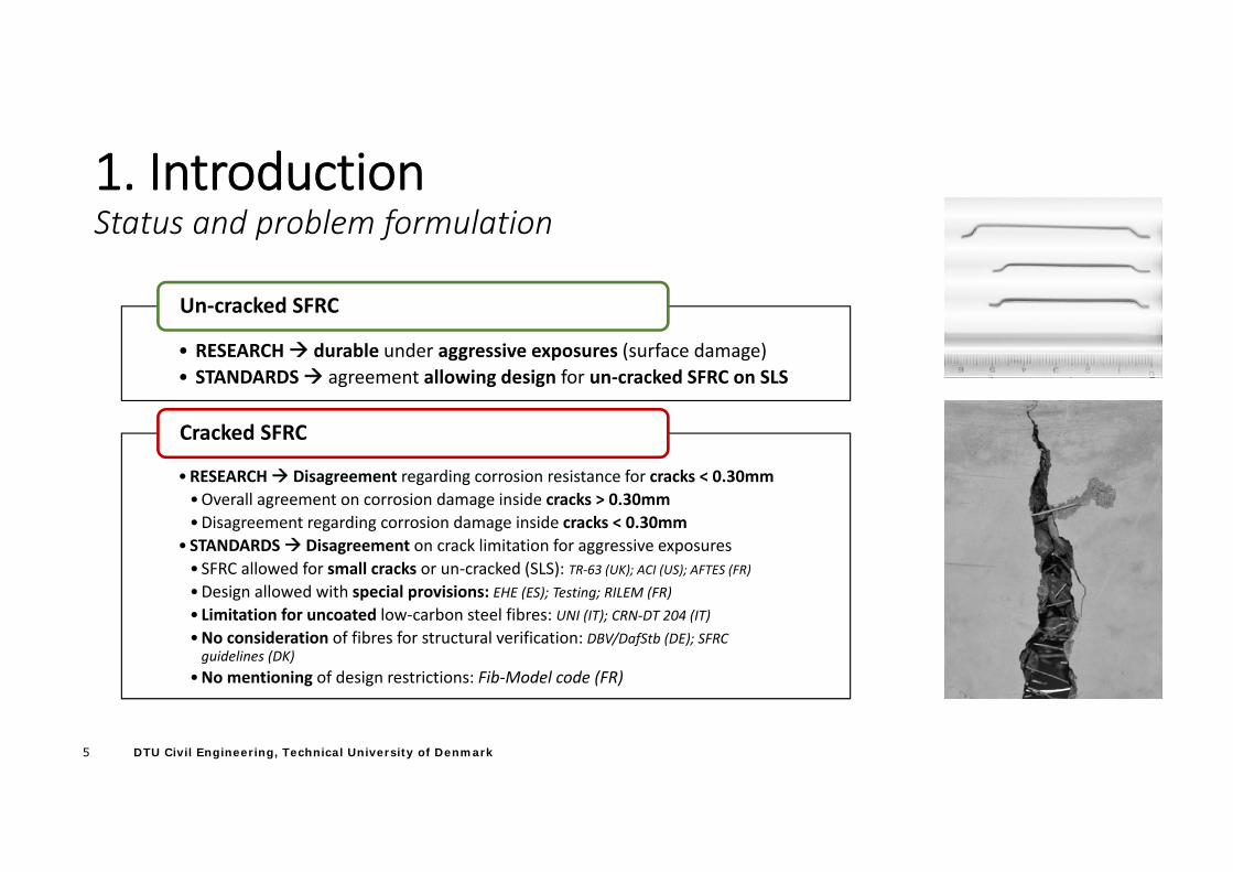
1. IntroductionStatus and problem formulation
• RESEARCH durable under aggressive exposures (surface damage)• STANDARDS agreement allowing design for un‐cracked SFRC on SLS
Un‐cracked SFRC
•RESEARCH Disagreement regarding corrosion resistance for cracks < 0.30mm•Overall agreement on corrosion damage inside cracks > 0.30mm•Disagreement regarding corrosion damage inside cracks < 0.30mm
• STANDARDS Disagreement on crack limitation for aggressive exposures• SFRC allowed for small cracks or un‐cracked (SLS): TR‐63 (UK); ACI (US); AFTES (FR)•Design allowed with special provisions: EHE (ES); Testing; RILEM (FR)• Limitation for uncoated low‐carbon steel fibres: UNI (IT); CRN‐DT 204 (IT)•No consideration of fibres for structural verification: DBV/DafStb (DE); SFRC guidelines (DK)
•No mentioning of design restrictions: Fib‐Model code (FR)
Cracked SFRC
6 DTU Civil Engineering, Technical University of Denmark
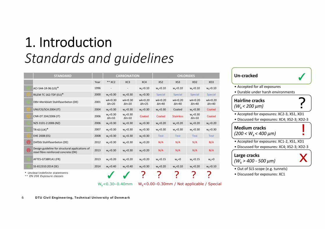
1. IntroductionStandards and guidelines
STANDARD CARBONATION CHLORIDES
Year ** XC2 XC3 XC4 XS2 XS3 XD2 XD3
ACI‐544‐1R‐96 (US)* 1996 ‐ ‐ wk<0.10 wk<0.10 wk<0.10 wk<0.10 wk<0.10
RILEM TC 162‐TDF (EU)* 2000 wk<0.30 wk<0.30 wk<0.30 Special Special Special Special
DBV‐Merkblatt Stahlfaserbeton (DE) 2001 wk<0.30Δh>20
wk<0.30Δh>20
wk<0.20Δh>25
wk<0.20Δh>40
wk<0.20Δh>40
wk<0.20Δh>40
wk<0.20Δh>40
UNI/CIS/SC4:2004 (IT) 2004 wk<0.30 wk<0.30 wk<0.30 wk<0.30 Coated wk<0.30 Coated
CNR‐DT 204/2006 (IT) 2006 wk<0.30Δh>10
wk<0.30Δh>10 Coated Coated Stainless wk<0.30
Δh>10 Coated
NZS 3101‐2:2006 (NZ) 2006 wk<0.30 wk<0.30 wk<0.30 wk<0.20 wk<0.20 wk<0.20 wk<0.20
TR‐63 (UK)* 2007 wk<0.30 wk<0.30 wk<0.30 wk<0.30 wk<0.30 wk<0.30 wk<0.30
EHE 2008 (ES) 2008 wk<0.30 wk<0.30 wk<0.30 Test Test Test Test
DAfStb Stahlfaserbeton (DE) 2012 wk<0.30 wk<0.30 wk<0.20 N/A N/A N/A N/A
Design guideline for structural applications of steel fibre reinforced concrete (DK) 2013 wk<0.30 wk<0.30 wk<0.20 N/A N/A N/A N/A
AFTES‐GT38R1A1 (FR) 2013 wk<0.20 wk<0.20 wk<0.20 wk<0.15 wk=0 wk<0.15 wk=0
SS‐812310:2014 (SE) 2014 wk<0.40 wk<0.40 wk<0.30 wk<0.20 wk<0.10 wk<0.20 wk<0.10
* Unclear/indefinite statements** EN 206 Exposure classes ✓ ✓ ? ? ? ??
Wk<0.30–0.40mm Wk<0.00–0.30mm / Not applicable / Special
Un‐cracked
• Accepted for all exposures• Durable under harsh environments
Hairline cracks(Wk < 200 µm)• Accepted for exposures: XC2‐3, XS1, XD1• Discussed for exposures: XC4; XS2‐3; XD2‐3
Medium cracks(200 < Wk < 400 µm)• Accepted for exposures: XC1‐2, XS1, XD1• Discussed for exposures: XC4; XS2‐3; XD2‐3
Large cracks(Wk > 400 ‐ 500 µm)• Out of SLS scope (e.g. tunnels)• Discussed for exposures: XC1
?
✓
x
!
7 DTU Civil Engineering, Technical University of Denmark
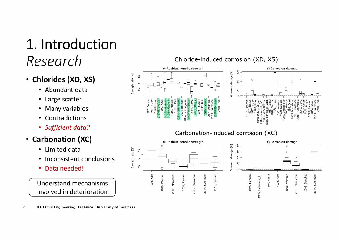
1. IntroductionResearch• Chlorides (XD, XS)
• Abundant data• Large scatter• Many variables• Contradictions• Sufficient data?
• Carbonation (XC)• Limited data• Inconsistent conclusions• Data needed!
1977
, Bat
son
1977
, Mor
se19
78, R
ider
1987
, Man
gat
1990
, Kos
a19
98, W
eyde
rt19
99, B
alou
ch19
99, H
anse
n19
99, O
neil
2000
, Nem
egee
r20
04, B
erna
rd20
04, M
ante
gazz
a20
05, N
ords
trom
2008
, Ser
na20
09, R
oque
2011
, Bur
atti
2011
, Sun
2014
, Abb
as20
14, A
nand
an20
14, K
aufm
ann
2015
, Ber
nard
2015
, Tra
n
-50
050
c) Residual tensile strength
Stre
ngth
ratio
[%]
1975
, Han
nant
1977
, Bat
son
1977
, Mor
se19
78, R
ider
1985
, Sch
upac
k_AU
1985
, Sch
upac
k_BA
T19
85, S
chup
ack_
LI19
85, S
chup
ack_
WES
1987
, Kam
al19
87, M
anga
t19
90, K
osa
1998
, Wey
dert
1999
, Bal
ouch
1999
, Dha
nase
kar
1999
, Han
sen
1999
, One
il20
05, N
ords
trom
2006
, Gan
esan
2008
, Kop
ecks
ko20
08, S
erna
2009
, Gra
eff
2009
, Roq
ue20
09, S
anch
ez20
14, A
bbas
2014
, Kau
fman
n20
15, T
ran
020
6010
0
d) Corrosion damage
Cor
rosi
on d
amag
e [%
]
Chloride-induced corrosion (XD, XS)
1991
, Ker
n
1998
, Wey
dert
2000
, Nem
egee
r
2004
, Ber
nard
2005
, Nor
dstro
m
2014
, Kau
fman
n
2015
, Ber
nard
-40
040
c) Residual tensile strength
Stre
ngth
ratio
[%]
1975
, Han
nant
1985
, Sch
upac
k_AU
1987
, Kam
al
1991
, Ker
n
1998
, Wey
dert
2005
, Nor
dstro
m
2009
, San
chez
2014
, Kau
fman
n
020
4060
80
d) Corrosion damage
Cor
rosi
on d
amag
e [%
]
Carbonation-induced corrosion (XC)
Understand mechanisms involved in deterioration
8 DTU Civil Engineering, Technical University of Denmark
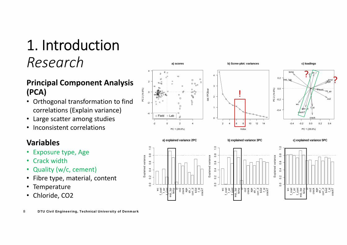
1. IntroductionResearchPrincipal Component Analysis (PCA)• Orthogonal transformation to find correlations (Explain variance)
• Large scatter among studies• Inconsistent correlations
Variables• Exposure type, Age• Crack width• Quality (w/c, cement)• Fibre type, material, content• Temperature• Chloride, CO2
-2 0 2 4
-4
-2
0
2
4
a) scores
PC 1 (28.6%)
PC
2 (1
4.8%
)
2 4 6 8 10 12 14
0
1
2
3
4
b) Scree-plot: variances
Index
dat.1
PC
$var
-0.4 -0.2 0.0 0.2 0.4
-0.4
-0.2
0.0
0.2
c) loadings
PC 1 (28.6%)
PC
2 (1
4.8%
)
wc
f_strf_cont
exp_typ
tempcl
co2
crack
age
str_r
corr_d
bind
f_ld
crackT
??
!
□ Field ○ Lab
wc
f_co
atf_
str
f_co
ntex
p_ty
pte
mp cl
co2
crac
kag
est
r_r
corr
_dbi
nd f_ld
crac
kT
a) explained variance 2PCE
xpla
ined
var
ianc
e
0.0
0.2
0.4
0.6
0.8
1.0
wc
f_co
atf_
str
f_co
ntex
p_ty
pte
mp cl
co2
crac
kag
est
r_r
corr
_dbi
nd f_ld
crac
kT
b) explained variance 3PC
Exp
lain
ed v
aria
nce
0.0
0.2
0.4
0.6
0.8
1.0
wc
f_co
atf_
str
f_co
ntex
p_ty
pte
mp cl
co2
crac
kag
est
r_r
corr
_dbi
nd f_ld
crac
kT
c) explained variance 5PC
Exp
lain
ed v
aria
nce
0.0
0.2
0.4
0.6
0.8
1.0
9 DTU Civil Engineering, Technical University of Denmark
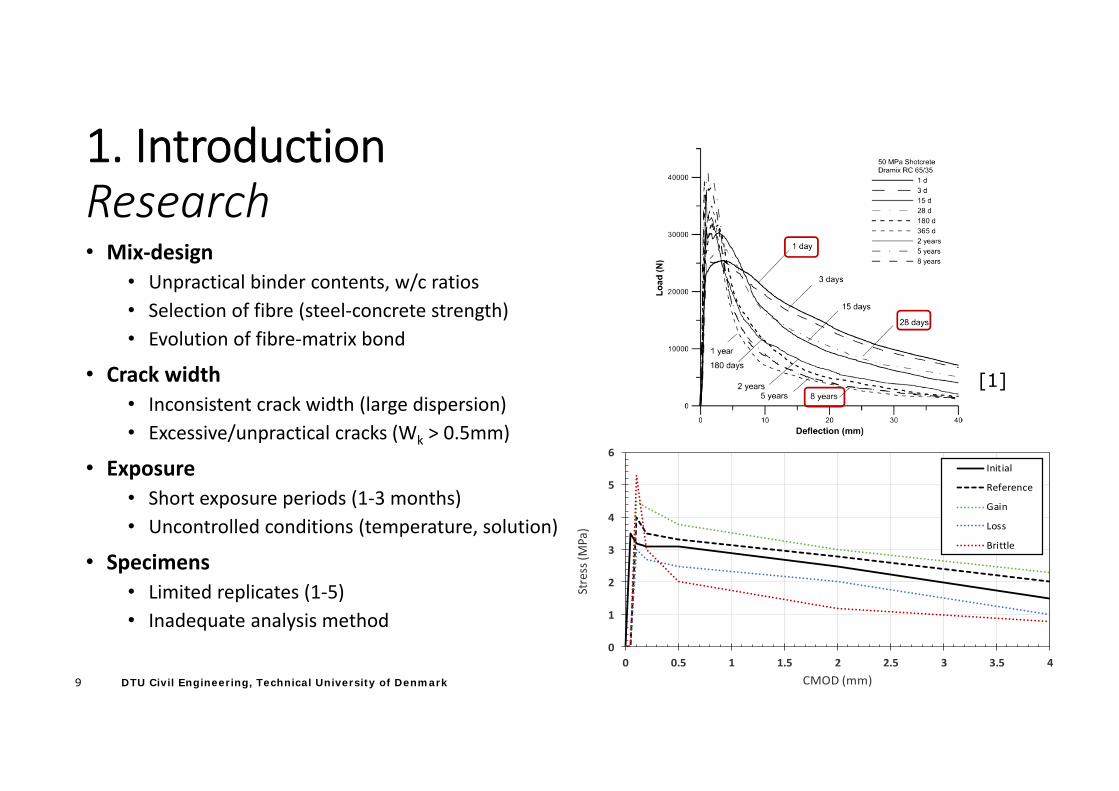
1. IntroductionResearch• Mix‐design
• Unpractical binder contents, w/c ratios• Selection of fibre (steel‐concrete strength)• Evolution of fibre‐matrix bond
• Crack width• Inconsistent crack width (large dispersion)• Excessive/unpractical cracks (Wk > 0.5mm)
• Exposure• Short exposure periods (1‐3 months)• Uncontrolled conditions (temperature, solution)
• Specimens• Limited replicates (1‐5)• Inadequate analysis method
0
1
2
3
4
5
6
0 0.5 1 1.5 2 2.5 3 3.5 4
Stress (M
Pa)
CMOD (mm)
Initial
Reference
Gain
Loss
Brittle
[1]
10 DTU Civil Engineering, Technical University of Denmark
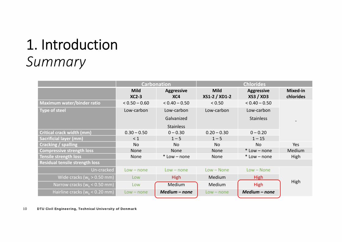
1. IntroductionSummary
Carbonation ChloridesMildXC2‐3
AggressiveXC4
MildXS1‐2 / XD1‐2
AggressiveXS3 / XD3
Mixed‐in chlorides
Maximum water/binder ratio < 0.50 – 0.60 < 0.40 – 0.50 < 0.50 < 0.40 – 0.50
‐
Type of steel Low‐carbon Low‐carbon
Galvanized
Stainless
Low‐carbon Low‐carbon
Stainless
Critical crack width (mm) 0.30 – 0.50 0 – 0.30 0.20 – 0.30 0 – 0.20Sacrificial layer (mm) < 1 1 – 5 1 – 5 1 – 15Cracking / spalling No No No No YesCompressive strength loss None None None * Low – none MediumTensile strength loss None * Low – none None * Low – none HighResidual tensile strength loss
Un‐cracked Low – none Low – none Low – None Low – None
HighWide cracks (wk > 0.50 mm) Low High Medium High
Narrow cracks (wk < 0.50 mm) Low Medium Medium HighHairline cracks (wk < 0.20 mm) Low – none Medium – none Low – none Medium – none
11 DTU Civil Engineering, Technical University of Denmark
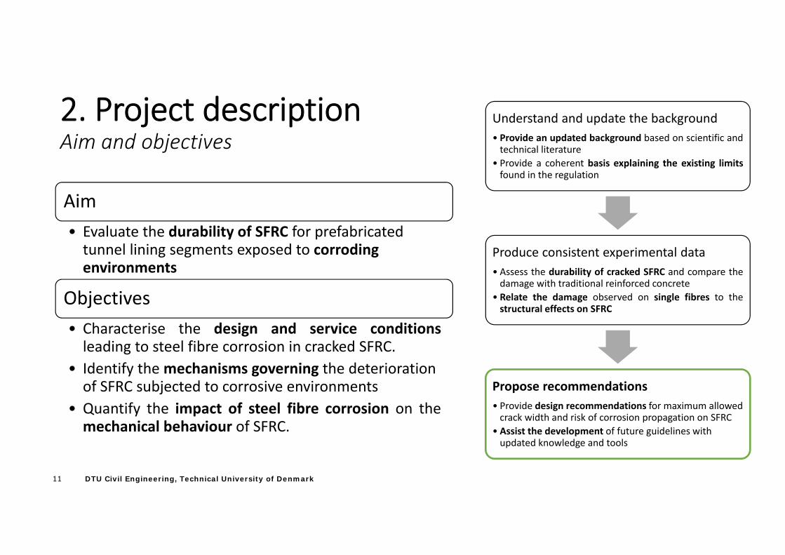
2. Project descriptionAim and objectives
Aim • Evaluate the durability of SFRC for prefabricated tunnel lining segments exposed to corroding environments
Objectives• Characterise the design and service conditionsleading to steel fibre corrosion in cracked SFRC.
• Identify the mechanisms governing the deterioration of SFRC subjected to corrosive environments
• Quantify the impact of steel fibre corrosion on themechanical behaviour of SFRC.
Understand and update the background• Provide an updated background based on scientific andtechnical literature
• Provide a coherent basis explaining the existing limitsfound in the regulation
Produce consistent experimental data• Assess the durability of cracked SFRC and compare thedamage with traditional reinforced concrete
• Relate the damage observed on single fibres to thestructural effects on SFRC
Propose recommendations• Provide design recommendations for maximum allowed crack width and risk of corrosion propagation on SFRC
• Assist the development of future guidelines with updated knowledge and tools
12 DTU Civil Engineering, Technical University of Denmark
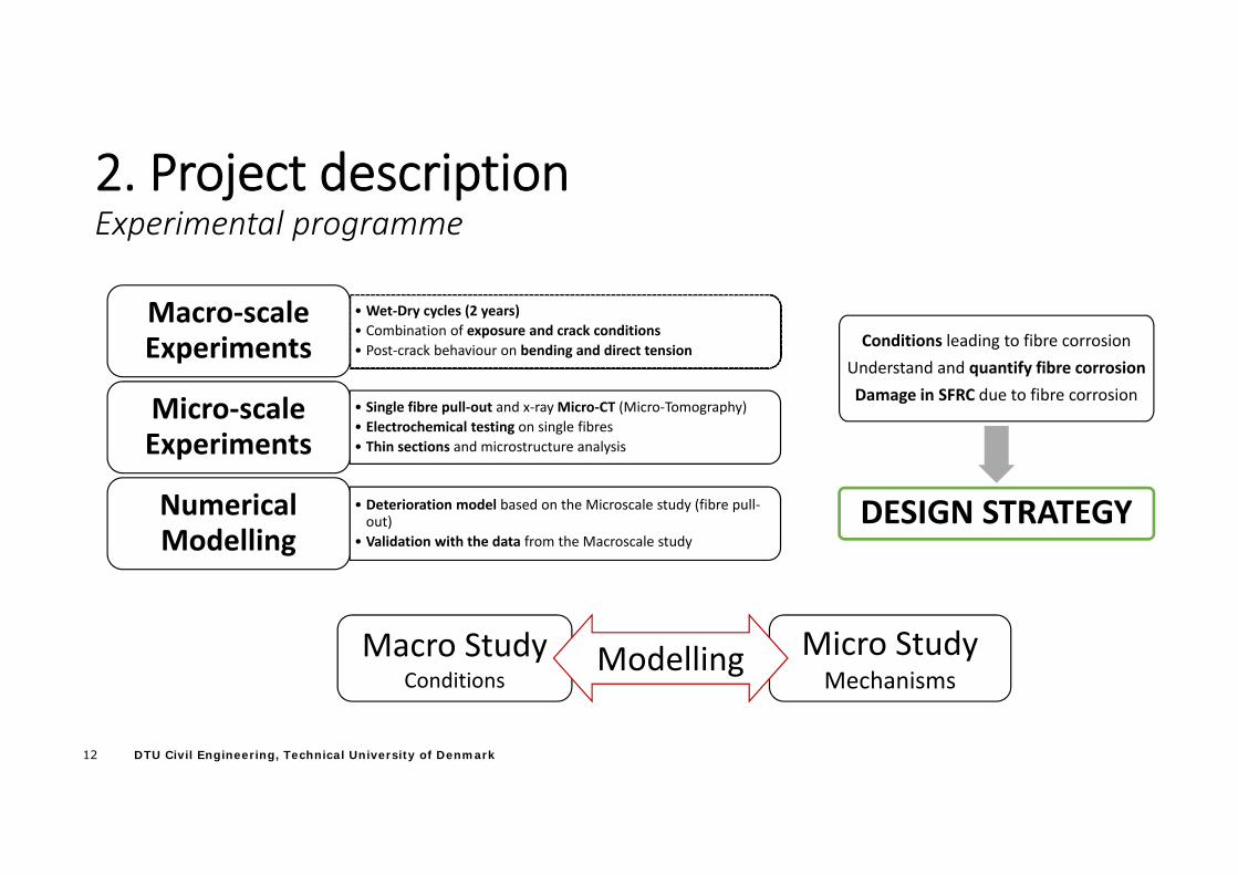
2. Project descriptionExperimental programme
• Wet‐Dry cycles (2 years)• Combination of exposure and crack conditions• Post‐crack behaviour on bending and direct tension
Macro‐scale Experiments
• Single fibre pull‐out and x‐ray Micro‐CT (Micro‐Tomography)• Electrochemical testing on single fibres• Thin sections and microstructure analysis
Micro‐scale Experiments
• Deterioration model based on the Microscale study (fibre pull‐out)
• Validation with the data from the Macroscale study
Numerical Modelling
Conditions leading to fibre corrosion Understand and quantify fibre corrosionDamage in SFRC due to fibre corrosion
DESIGN STRATEGY
Macro StudyConditions
Micro StudyMechanisms
Modelling
13 DTU Civil Engineering, Technical University of Denmark
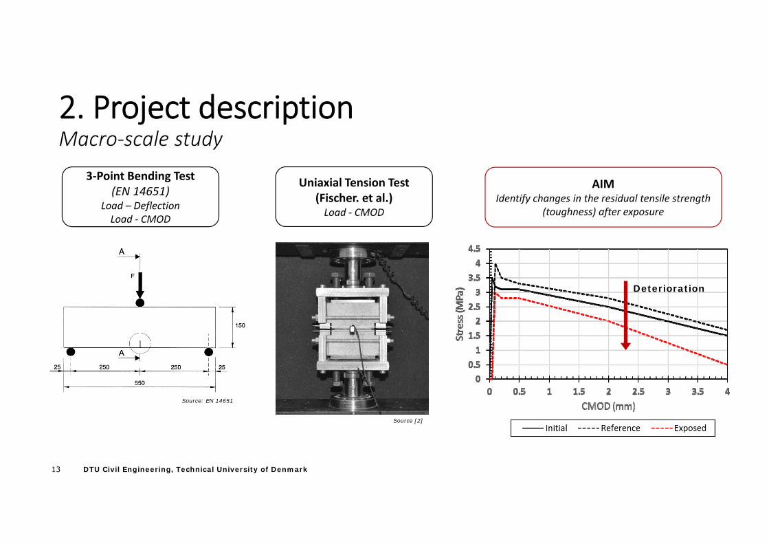
2. Project descriptionMacro‐scale study
3‐Point Bending Test(EN 14651)
Load – DeflectionLoad ‐ CMOD
Source: EN 14651
Uniaxial Tension Test(Fischer. et al.)Load ‐ CMOD
Source [2]
AIMIdentify changes in the residual tensile strength
(toughness) after exposure
Deterioration
14 DTU Civil Engineering, Technical University of Denmark
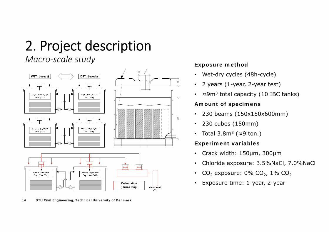
2. Project descriptionMacro‐scale study
Exposure method
• Wet-dry cycles (48h-cycle)
• 2 years (1-year, 2-year test)
• ≈9m3 total capacity (10 IBC tanks)
Amount of specimens
• 230 beams (150x150x600mm)
• 230 cubes (150mm)
• Total 3.8m3 (≈9 ton.)
Experiment variables
• Crack width: 150µm, 300µm
• Chloride exposure: 3.5%NaCl, 7.0%NaCl
• CO2 exposure: 0% CO2, 1% CO2
• Exposure time: 1-year, 2-year
15 DTU Civil Engineering, Technical University of Denmark
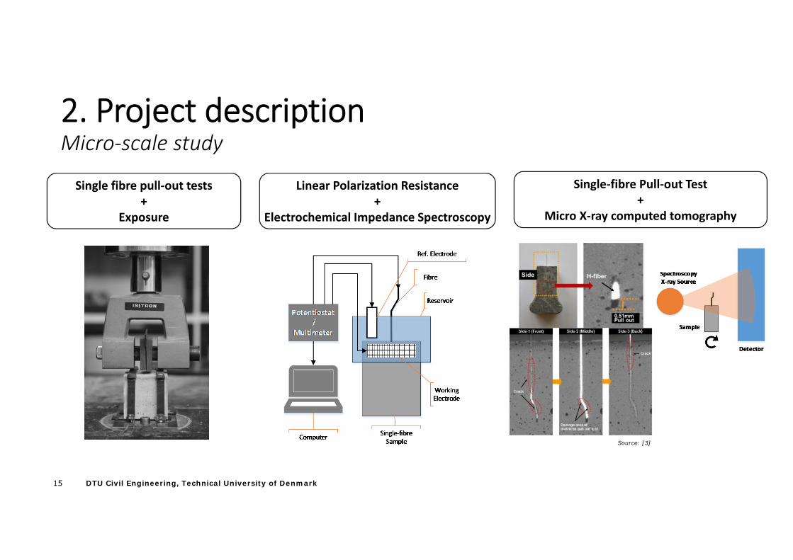
2. Project descriptionMicro‐scale study
Source: [3]
Single‐fibre Pull‐out Test+
Micro X‐ray computed tomography
Linear Polarization Resistance+
Electrochemical Impedance Spectroscopy
Single fibre pull‐out tests+
Exposure
16 DTU Civil Engineering, Technical University of Denmark
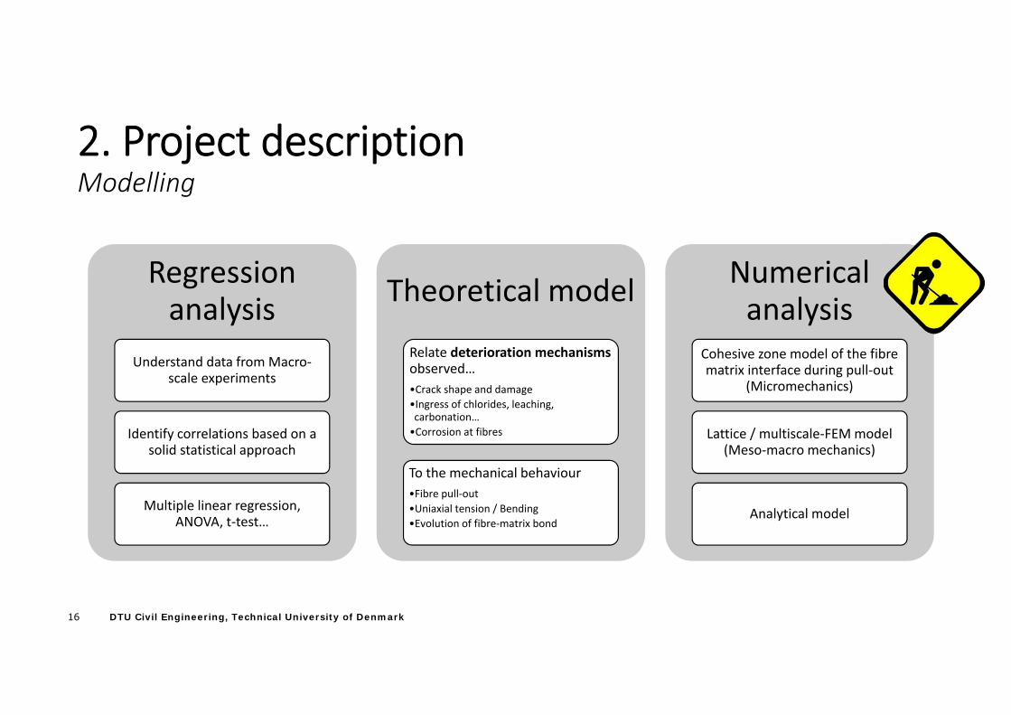
2. Project descriptionModelling
Regression analysis
Understand data from Macro‐scale experiments
Identify correlations based on a solid statistical approach
Multiple linear regression, ANOVA, t‐test…
Theoretical model
Relate deterioration mechanisms observed…•Crack shape and damage•Ingress of chlorides, leaching, carbonation…•Corrosion at fibres
To the mechanical behaviour•Fibre pull‐out•Uniaxial tension / Bending •Evolution of fibre‐matrix bond
Numerical analysis
Cohesive zone model of the fibre matrix interface during pull‐out
(Micromechanics)
Lattice / multiscale‐FEM model (Meso‐macro mechanics)
Analytical model
17 DTU Civil Engineering, Technical University of Denmark
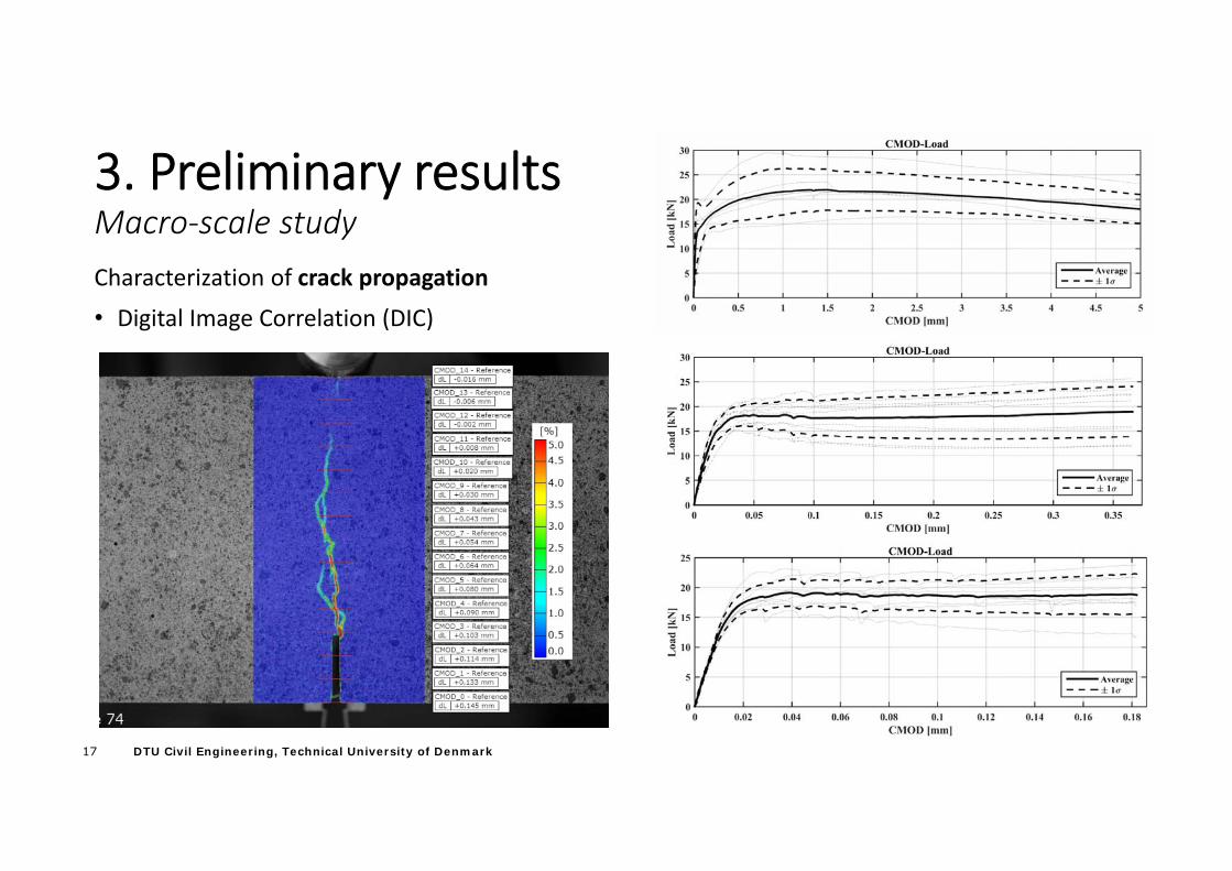
3. Preliminary resultsMacro‐scale studyCharacterization of crack propagation
• Digital Image Correlation (DIC)
18 DTU Civil Engineering, Technical University of Denmark
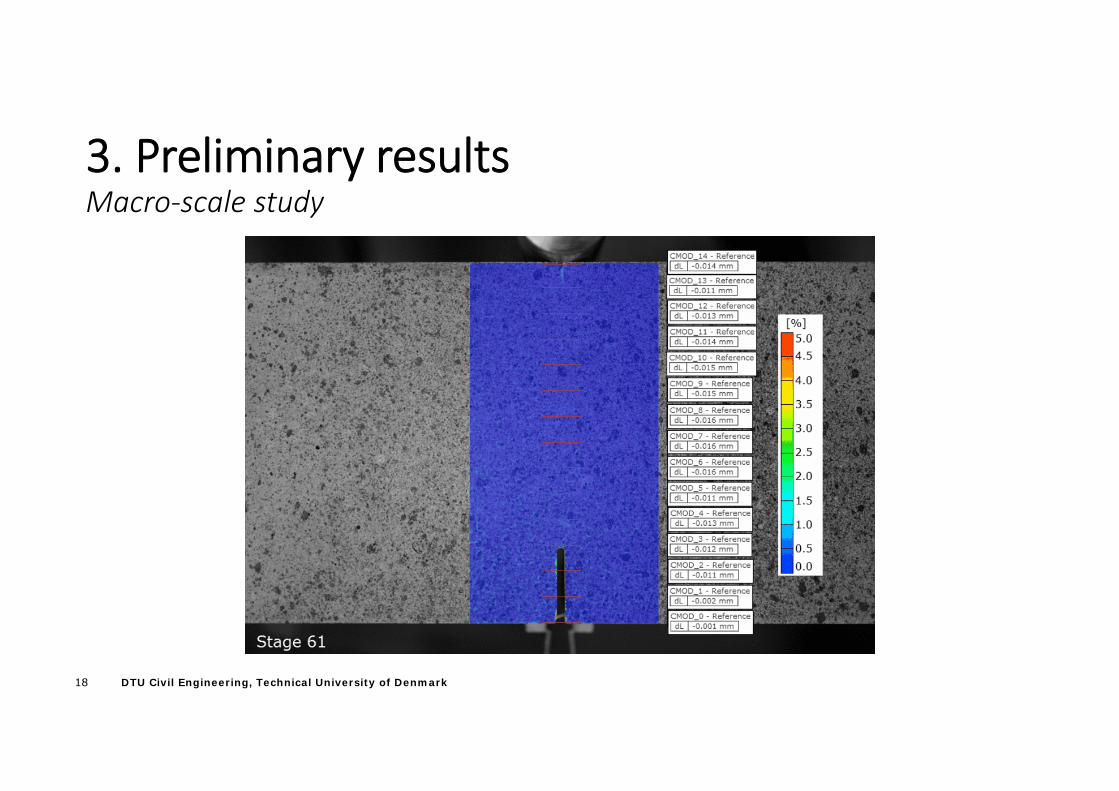
3. Preliminary resultsMacro‐scale study
19 DTU Civil Engineering, Technical University of Denmark
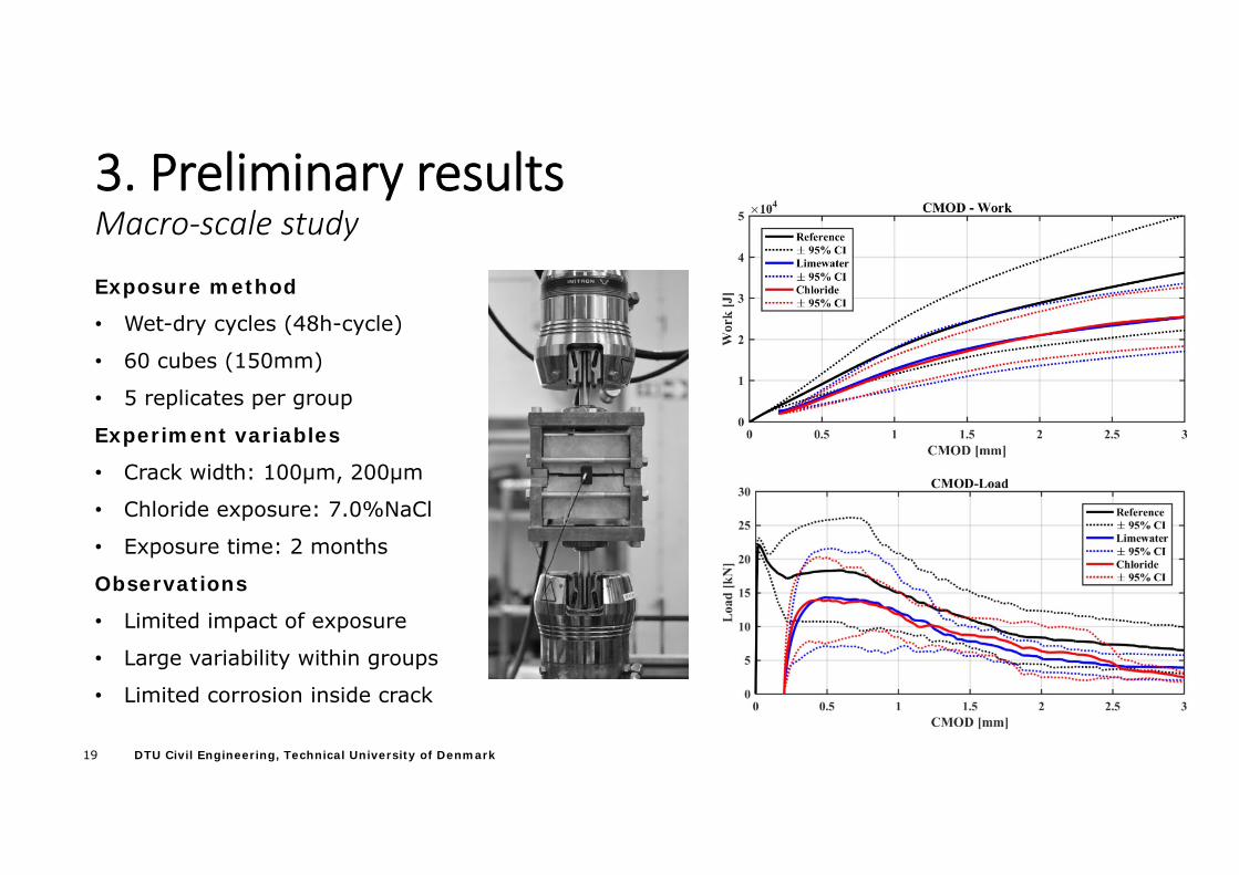
3. Preliminary resultsMacro‐scale study
Exposure method
• Wet-dry cycles (48h-cycle)
• 60 cubes (150mm)
• 5 replicates per group
Experiment variables
• Crack width: 100µm, 200µm
• Chloride exposure: 7.0%NaCl
• Exposure time: 2 months
Observations
• Limited impact of exposure
• Large variability within groups
• Limited corrosion inside crack
20 DTU Civil Engineering, Technical University of Denmark
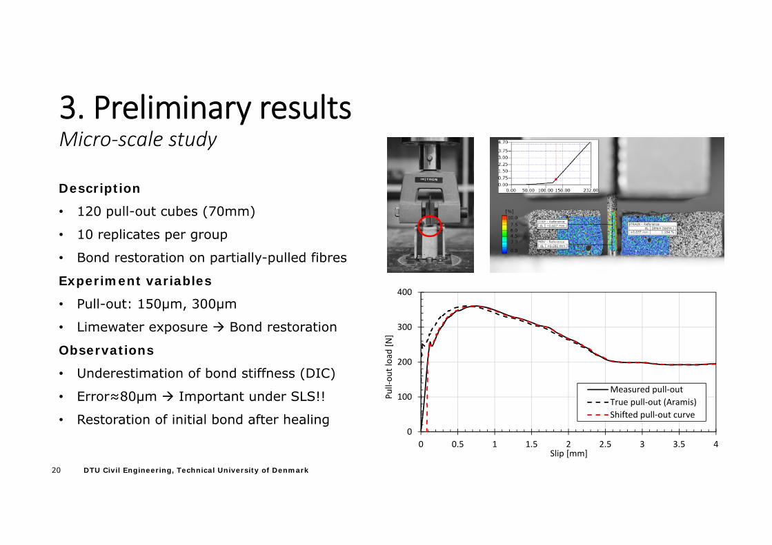
3. Preliminary resultsMicro‐scale study
Description
• 120 pull-out cubes (70mm)
• 10 replicates per group
• Bond restoration on partially-pulled fibres
Experiment variables
• Pull-out: 150µm, 300µm
• Limewater exposure Bond restoration
Observations
• Underestimation of bond stiffness (DIC)
• Error≈80µm Important under SLS!!
• Restoration of initial bond after healing0
100
200
300
400
0 0.5 1 1.5 2 2.5 3 3.5 4
Pull‐ou
t load [N]
Slip [mm]
Measured pull‐outTrue pull‐out (Aramis)Shifted pull‐out curve
21 DTU Civil Engineering, Technical University of Denmark
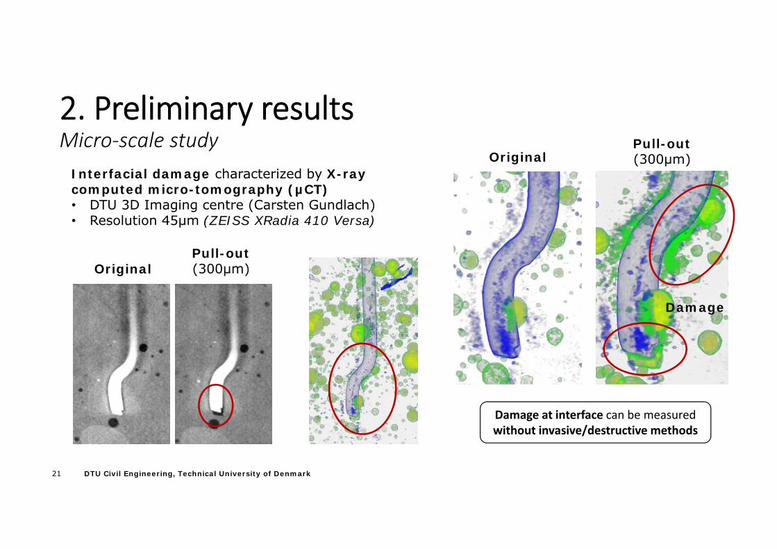
2. Preliminary resultsMicro‐scale study
OriginalPull-out(300µm)
Damage
Damage at interface can be measured without invasive/destructive methods
OriginalPull-out(300µm)
Interfacial damage characterized by X-ray computed micro-tomography (µCT)• DTU 3D Imaging centre (Carsten Gundlach)• Resolution 45µm (ZEISS XRadia 410 Versa)
22 DTU Civil Engineering, Technical University of Denmark
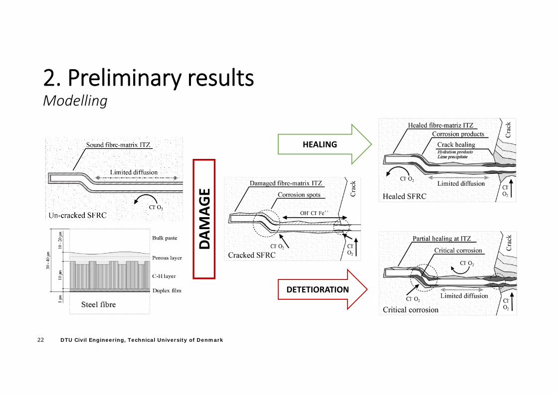
2. Preliminary resultsModelling
HEALING
DETETIORATION
DAMAG
E
23 DTU Civil Engineering, Technical University of Denmark
4. Summary
• Discrepancies regarding durability of SFRC exposed to chlorides and carbonation limit the use of SFRC in civil infrastructure
• Former research does not focus on damage mechanisms and provides a limited explanation for the damage reported
• Multiscale investigation combines performance data (macro‐scale) with explanation of mechanisms (Micro‐scale) trough numerical modelling
• Preliminary Macro‐scale results show a large variability within same SFRC group and limited corrosion damage at short exposures
• Preliminary Micro‐scale results reveal underestimation of fibre‐matrix bond stiffness and show damage at fibre‐matrix interface during pull‐out
24 DTU Civil Engineering, Technical University of Denmark
4. References[1] E. S. Bernard, “Age‐dependent changes in post‐crack performance of fibre reinforced shotcrete linings,” Tunn. Undergr. Sp. Technol., vol. 49, pp. 241–248, Jun. 2015.[2] I. Paegle, Characterization and modeling of fiber reinforced concrete for structural applications in beams and plates. 2015.[3] T. H. Ahn, D. J. Kim, and S. H. Kang, “Crack Self‐Healing Behavior of High Performance Fiber Reinforced Cement Composites Under Various Environmental Conditions,” in Earth and Space 2012, 2012, pp. 635–640.
S. Abbas, “Structural and Durability Performance of Precast Segmental Tunnel Linings,” University of Western Ontario, 2014.B. De Rivaz, “Durability issue for SFRC precast segment in tunnelling application,” in WUTC2010, 2010, pp. 1–10.R. Weydert and P. Schiessl, “Korrosion von Stahlfasern in gerissenem und ungerissenem Stahlfaserbeton. Abschlussbericht,” Bergisch Gladbach (Germany), 1998.D. J. Hannant and J. Edgington, “Durability of steel fibre concrete,” in Rilem Symposium 1975: Fibre reinforced cement and concrete, 1975, pp. 159–169.D. C. Morse and G. R. Williamson, “Corrosion behavior of steel fibrous concrete,” Dept. of Defense Dept. of the Army Corps of Engineers Construction Engineering Research Laboratory ;, Champaign Ill., 1977.P. S. Mangat and K. Gurusamy, “Corrosion resistance of steel fibres in concrete under marine exposure,” Cem. Concr. Res., vol. 18, no. 1, pp. 44–54, Jan. 1988.P. S. Mangat, “Long‐term properties of steel fibre reinforced marine concrete,” Mater. Struct. Matériaux Constr., vol. 20, no. 4, pp. 273–282, 1987.P. S. Mangat and K. Gurusamy, “Permissible crack widths in steel fibre reinforced marine concrete,” Mater. Struct., vol. 20, no. 5, pp. 338–347, Sep. 1987.K. Kosa and A. E. Naaman, “Corrosion of Steel Fiber Reinforced Concrete,” ACI Mater. J., vol. 87, no. 1, pp. 27–37, 1990.J.‐L. Granju and S. U. Balouch, “Corrosion of steel fibre reinforced concrete from the cracks,” Cem. Concr. Res., vol. 35, no. 3, pp. 572–577, Mar. 2005.D. Nemegeer, J. Vanbrabant, and H. Stang, “Final report on Durability of Steel Fibre Reinforced Concrete,” Copenhagen, Denmark, 2000.E. Nordström, “Durability of Sprayed Concrete Steel fibre corrosion in cracks,” Lulea University of Technology, 2005.R. Roque, N. Kim, B. Kim, and G. Lopp, “Durability of Fiber‐Reinforced Concrete in Florida Environments,” Florida, USA, 2009.E. S. Bernard, “Effect of Exposure on Post‐crack Performance of FRC for Tunnel Segments,” in SEE Tunnel:Promoting Tunneling in SEE Region ‐ ITA WTC 2015, 2015, p. 13.C. Frazão, A. Camões, J. Barros, and D. Gonçalves, “Durability of steel fiber reinforced self‐compacting concrete,” Constr. Build. Mater., vol. 80, no. 2015, pp. 155–166, Apr. 2015.E. S. Bernard, “Age‐dependent changes in post‐crack performance of fibre reinforced shotcrete linings,” Tunn. Undergr. Sp. Technol., vol. 49, pp. 241–248, Jun. 2015.E. S. Bernard, “Durability of cracked fibre reinforced shotcrete,” in Shotcrete: More Engineering Developments: Proceedings of the Second International Conference on Engineering Developments in Shotcrete, 2004, pp. 59–66.C. G. Berrocal, I. Löfgren, and K. Lundgren, “Experimental Investigation on Rebar Corrosion in Combination with Fibres,” in XXII Nordic Concrete Research Symposium, 2014, pp. 1–4.C. Dauberschmidt, “Untersuchungen zu den Korrosionsmechanismen von Stahlfasern in chloridhaltigem Beton,” Munich University, 2006.

25 DTU Civil Engineering, Technical University of Denmark
THANK YOU
Questions?