short-circuits in es
TRANSCRIPT

- 1 -
Short-circuits in ES
Short-circuit: • cross fault, quick emergency change in ES • the most often fault in ES • transient events occur during short-circuits
Short-circuit formation: • fault connection between phases or between phase(s) and the ground
in the system with the grounded neutral point
Main causes: • insulation defect caused by overvoltage • direct lightning strike • insulation aging • direct damage of overhead lines or cables
- 2 -
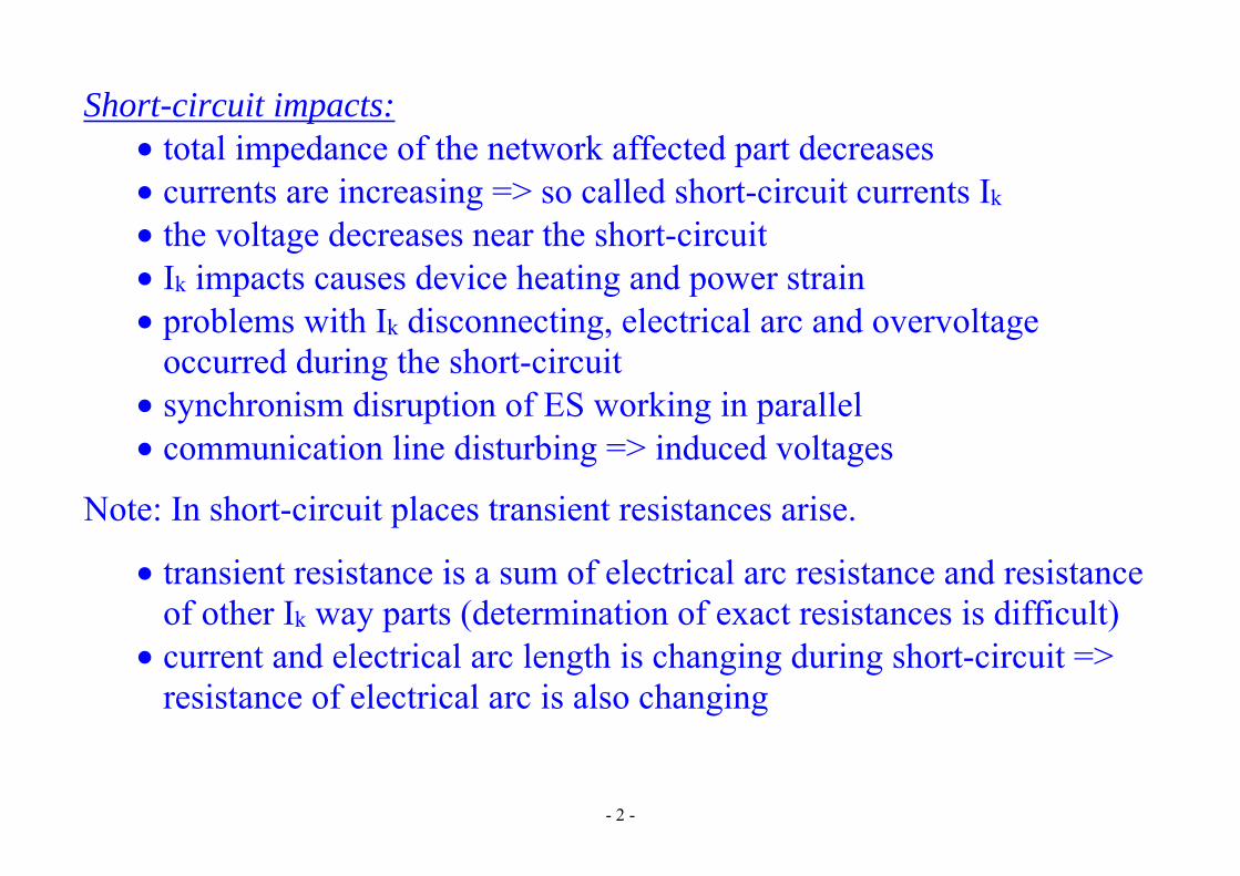
Short-circuit impacts: • total impedance of the network affected part decreases • currents are increasing => so called short-circuit currents Ik • the voltage decreases near the short-circuit • Ik impacts causes device heating and power strain • problems with Ik disconnecting, electrical arc and overvoltage
occurred during the short-circuit • synchronism disruption of ES working in parallel • communication line disturbing => induced voltages
Note: In short-circuit places transient resistances arise.
• transient resistance is a sum of electrical arc resistance and resistance of other Ik way parts (determination of exact resistances is difficult)
• current and electrical arc length is changing during short-circuit => resistance of electrical arc is also changing

- 3 -
• transient resistances are neglected for Ik calculation (dimensioning of electrical devices) → perfect short-circuits
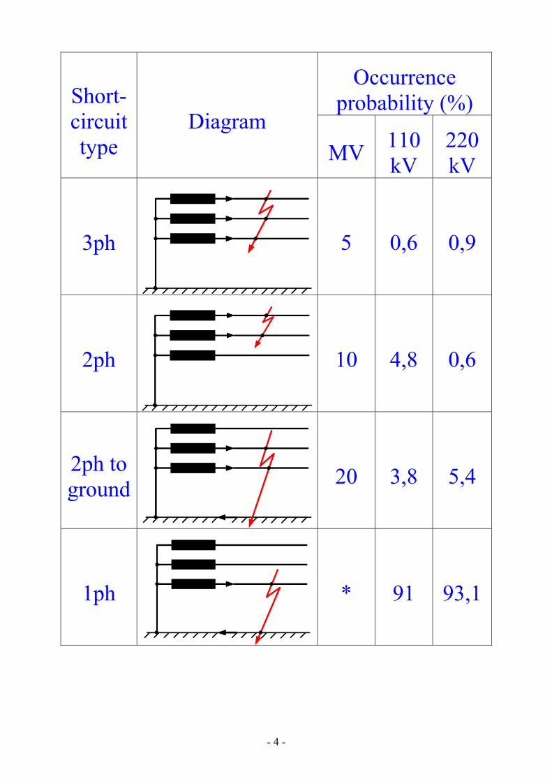
Short-circuits types
Symmetrical short-circuits: • Three-phase short-circuit => all 3 phases are affected by short-circuit
little occurrence in the case of overhead lines the most occurrences in the case of cable lines => other kinds of
faults change to 3ph short-circuit due to electrical-arc impact
Unbalanced (asymmetrical) short-circuits: • phase-to-phase short-circuit • double-phase-to-ground short-circuit • single-phase-to-ground short-circuit:
in MV a different kind of fault => so called ground fault in case of ground fault in MV (insulated or indirectly grounded
neutral point) => no change in LV (grounded neutral point)
- 4 -
Short-circuit type
Diagram
Occurrence probability (%)
MV 110 kV
220 kV
3ph 5 0,6 0,9
2ph 10 4,8 0,6
2ph to ground 20 3,8 5,4
1ph * 91 93,1
- 5 -
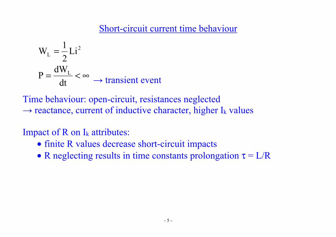
Short-circuit current time behaviour
2L Li
21W =
∞<=dt
dWP L → transient event
Time behaviour: open-circuit, resistances neglected → reactance, current of inductive character, higher Ik values
Impact of R on Ik attributes:
• finite R values decrease short-circuit impacts • R neglecting results in time constants prolongation τ = L/R
- 6 -
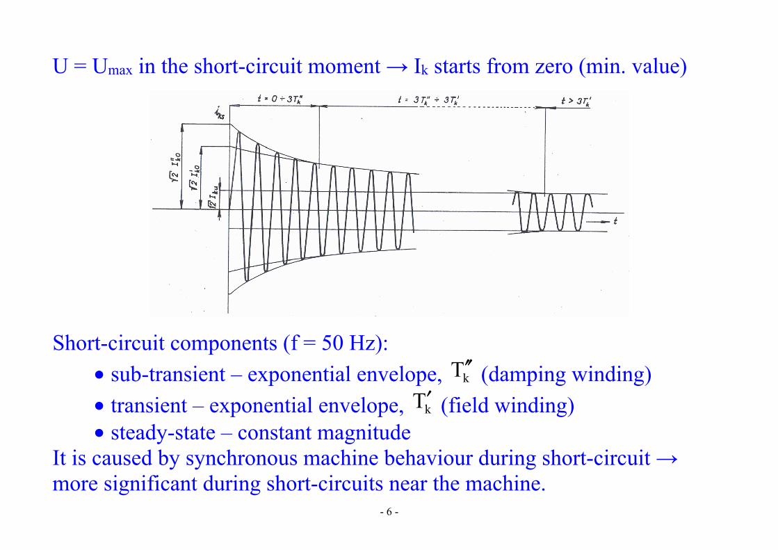
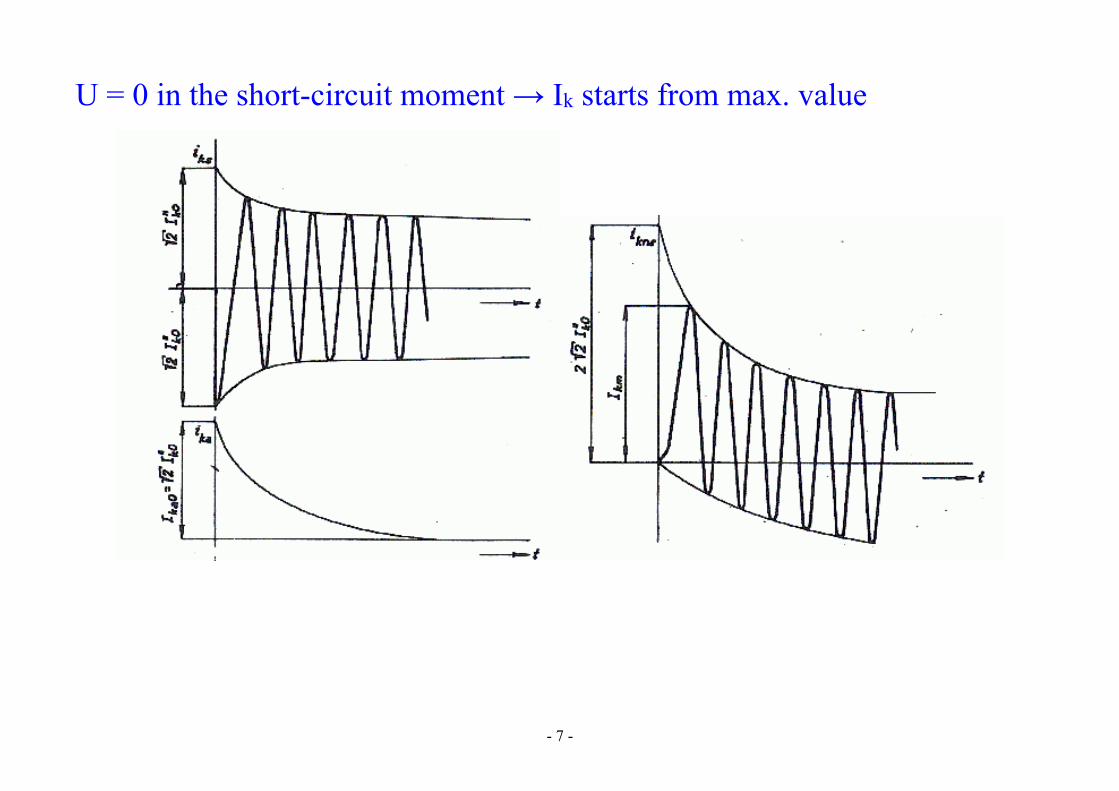
U = Umax in the short-circuit moment → Ik starts from zero (min. value)
Short-circuit components (f = 50 Hz): • sub-transient – exponential envelope, kT ′′ (damping winding) • transient – exponential envelope, kT′ (field winding) • steady-state – constant magnitude
It is caused by synchronous machine behaviour during short-circuit → more significant during short-circuits near the machine.
- 7 -
U = 0 in the short-circuit moment → Ik starts from max. value
- 8 -
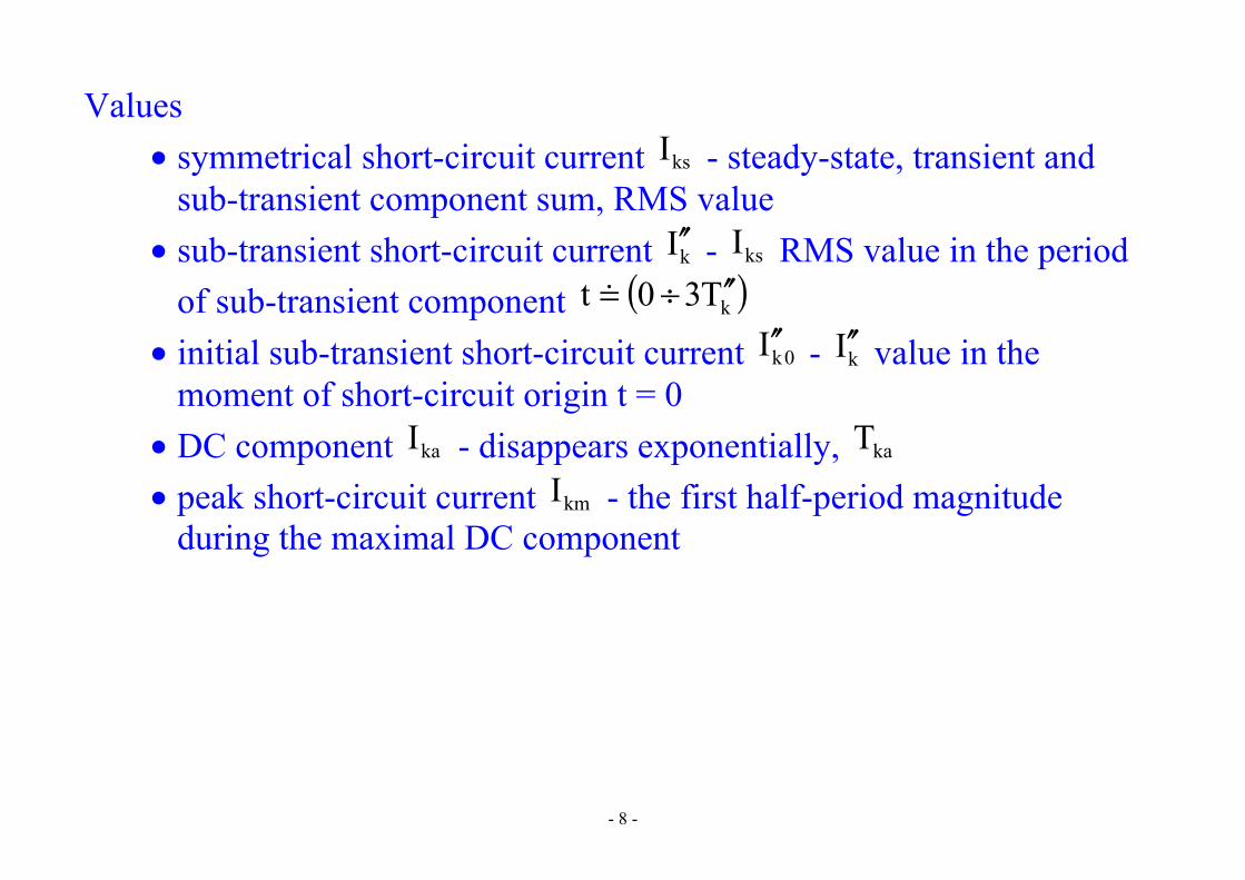
Values • symmetrical short-circuit current ksI - steady-state, transient and
sub-transient component sum, RMS value • sub-transient short-circuit current kI ′′ - ksI RMS value in the period
of sub-transient component ( )kT30t ′′÷= • initial sub-transient short-circuit current 0kI ′′ - kI ′′ value in the
moment of short-circuit origin t = 0 • DC component kaI - disappears exponentially, kaT • peak short-circuit current kmI - the first half-period magnitude
during the maximal DC component

- 9 -
Short-circuits in 3ph system
Conversion between phase values and symmetrical components
( ) ( )( )120
0
2
1
2
2
C
B
A
ABC UTUUU
1aa1aa111
UUU
U =
=
=
( ) ( )( )ABC1
C
B
A2
2
0
2
1
120 UTUUU
111aa1aa1
31
UUU
U −=
=
=
Impedance matrix in symmetrical components (for series sym. segment)
( )
′+′−
′−=
=Z2Z00
0ZZ000ZZ
Z000Z000Z
Z
0
2
1
120

- 10 -
3ph system during short-circuit – internal generator voltage E (or Ui)
( ) ( )( ) ( )ABCABCABCABC UIZE +=
Symmetrical system (independent systems 1, 2, 0)
( ) ( )( ) ( )120120120120 UIZE += 0000
2222
1111
UIZE
UIZE
UIZE
+=
+=
+=

- 11 -
Generator symmetrical voltage → only positive sequence component Reference phase A:
( ) ( )( )
=
=
== −
00E
00
E
EaEa
E
111aa1aa1
31ETE
A
A
A2
A2
2
ABC1
120
+
=
=
0
2
1
0
2
1
0
2
1
0
2
1
UUU
III
Z000Z000Z
00E
EEE
Negative and zero sequence are caused by voltage unbalance in the faulted place.
- 12 -
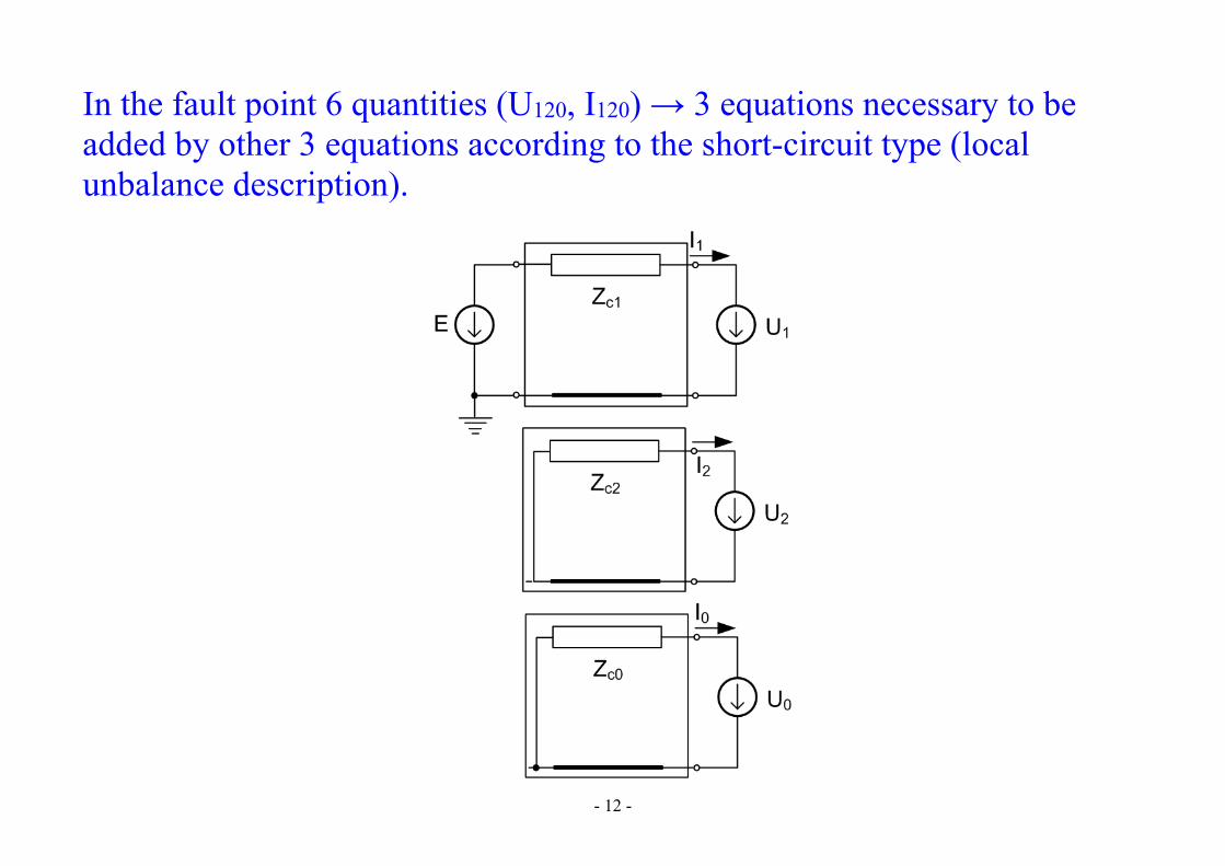
In the fault point 6 quantities (U120, I120) → 3 equations necessary to be added by other 3 equations according to the short-circuit type (local unbalance description).
- 13 -
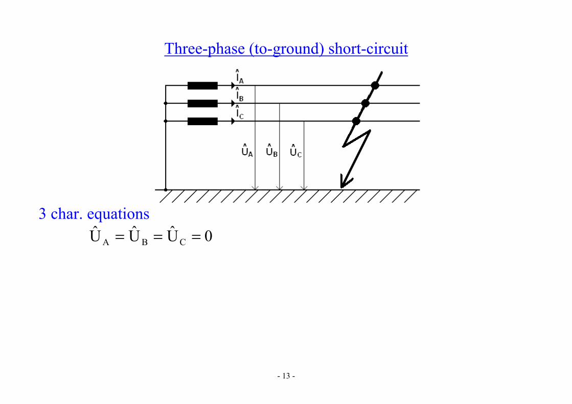
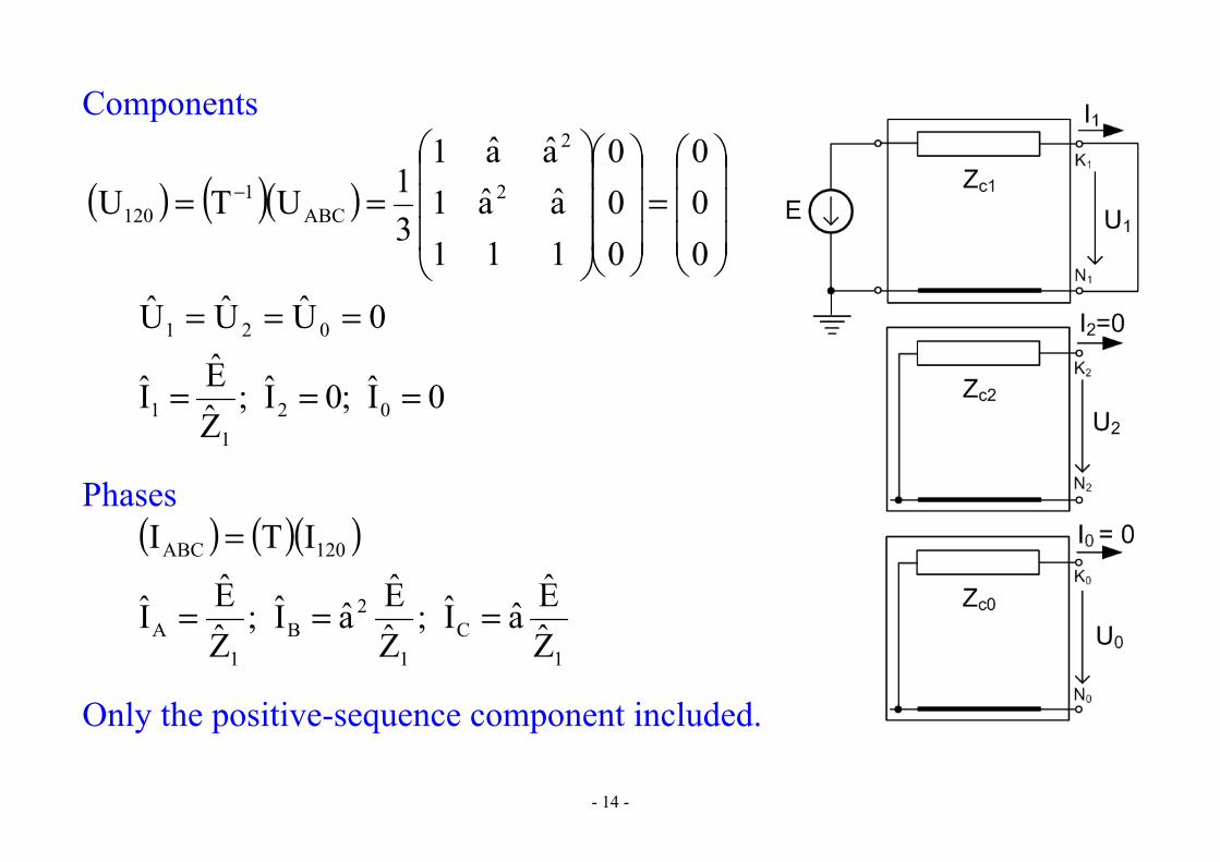
Three-phase (to-ground) short-circuit
3 char. equations
0UUU CBA ===
- 14 -
Components
( ) ( )( )
=
== −
000
000
111aa1aa1
31UTU 2
2
ABC1
120
0UUU 021 ===
0I;0I;ZEI 02
11 ===
Phases ( ) ( )( )120ABC ITI =
1C
1
2B
1A Z
EaI;ZEaI;
ZEI ===
Only the positive-sequence component included.

- 15 -
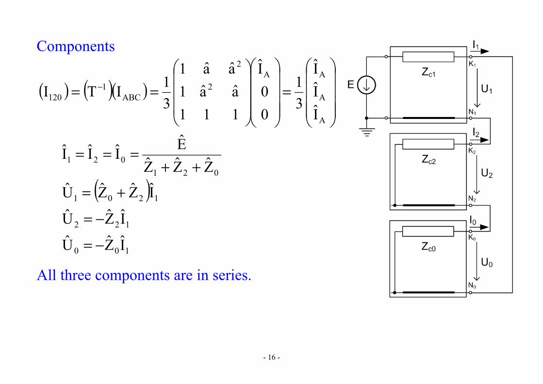
Single-phase-to-ground short-circuit
3 char. equations
0II;0U CBA ===
- 16 -
Components
( ) ( )( )
=
== −
A
A
AA2
2
ABC1
120
III
31
00I
111aa1aa1
31ITI
021
021 ZZZEIII
++===
( )
100
122
1201
IZU
IZU
IZZU
−=
−=
+=
All three components are in series.

- 17 -
Phases
( ) ( )( )
=
==
00I3
III
1aa1aa111
ITI1
1
1
1
2
2120ABC
0I;0I;ZZZ
E3I CB021
A ==++
=
( ) ( )( )( )
( ) ( )( ) ( )
1
022
02
22
10
12
120
2
2120ABC I
Z1aZaaZ1aZaa
0
IZIZ
IZZ
1aa1aa111
UTU
−+−−+−=
−−
+
==

- 18 -
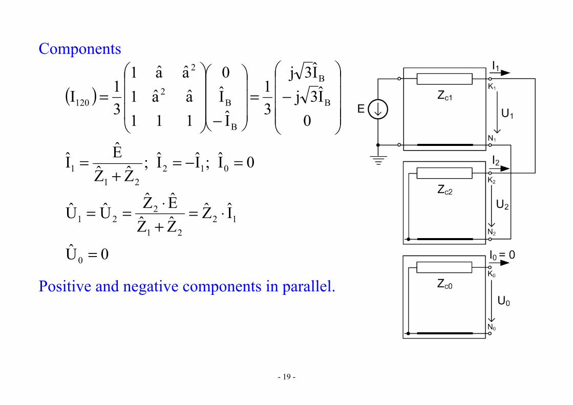
Phase-to-phase short-circuit
3 char. equations
0I;II;UU ACBCB =−==
- 19 -
Components
( )
−=
−
=0
I3jI3j
31
II0
111aa1aa1
31I B
B
B
B2
2
120
0I;II;ZZ
EI 01221
1 =−=+
=
0U
IZZZEZUU
0
1221
221
=
⋅=+⋅==
Positive and negative components in parallel.
- 20 -
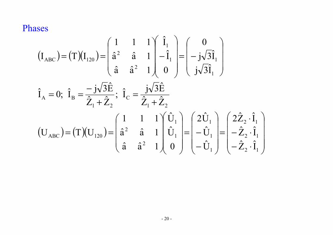
Phases
( ) ( )( )
−=
−
==
1
11
1
2
2120ABC
I3jI3j
0
0I
I
1aa1aa111
ITI
21C
21BA ZZ
E3jI;ZZE3jI;0I
+=
+−==
( ) ( )( )
⋅−⋅−⋅
=
−−=
==
12
12
12
1
1
1
1
1
2
2120ABC
IZIZIZ2
UUU2
0UU
1aa1aa111
UTU
- 21 -
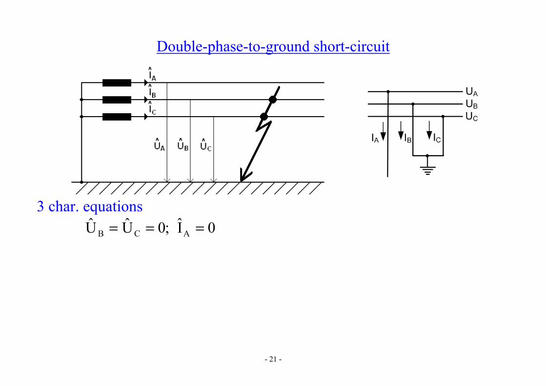
Double-phase-to-ground short-circuit
3 char. equations
0I;0UU ACB ===

- 22 -
Components
( )
=
=
A
A
AA2
2
120
UUU
31
00
U
111aa1aa1
31U
120
201
20
02
20
201
1
IZZ
ZI;IZZ
ZI
ZZZZZ
EI
+−=
+−=
++
=
20
201
20
20
021
ZZZZZ
ZZZZE
UUU
++
+===

- 23 -
All three components are in parallel.
Phases ( ) ( )( )120ABC ITI =
( )201021
22
20
B ZZZZZZ)1a(Z)aa(ZEI
++−+−=
( )201021
22
0C ZZZZZZ
)1a(Z)aa(ZEI++
−+−=
( ) ( )( )
=
==
00U3
UUU
1aa1aa111
UTU1
1
1
1
2
2120ABC
- 24 -
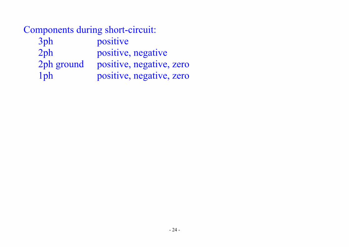
Components during short-circuit: 3ph positive 2ph positive, negative 2ph ground positive, negative, zero
1ph positive, negative, zero

- 25 -
Short-circuits calculation by means of relative values
Relative values – related to a defined base.
base power (3ph) Sv (VA) base voltage (phase-to-phase) Uv (V) base current Iv (A) base impedance Zv (Ω)
vvv IU3S =
v
vfv I
UZ =
Relative impedance
2v
v2vf
v
vf
vf
vf
v
v
vfv USZ
U3SZ
U3U3
UIZ
IUZ
ZZz =====

- 26 -
Initial sub-transient short-circuit current (3ph short-circuit)
1
fA0k
Z
UII ==′′
v
2v
11 SUzZ =
v
1v
v
1
v
2v
1
v
0k Iz1
U3S
z1
SUz
3U
I ===′′
Initial sub-transient short-circuit power
v11
vv0kv0k S
z1
zIU3IU3S ==′′=′′

- 27 -
Similarly for 1ph short-circuit
v021
)1(0k I
zzz3I
++=′′
2ph short-circuit
v21
)2(0k I
zz3I
+=′′
Note: Sometimes it is respected generator loading, more precisely higher internal generator voltage than nominal one.
v1
0k Iz1kI =′′
k > 1

- 28 -
( ) )3(k
)1(k I5,10I ′′÷=′′
)3(k
)2(k I
23I ′′=′′
)3(k
)z2(k I3
23I ′′
÷=′′

- 29 -
Short-circuit currents impacts
Mechanical impacts Influence mainly at tightly placed stiff conductors, supporting insulators, disconnectors, construction elements,… Forces frequency 2f at AC → dynamic strain.
Force on the conductor in magnetic field )N(sinlIBF α⋅⋅⋅= )T(HB ⋅μ= )m/H(104 7
0−⋅π=μ
α – angle between mag. induction vector and the conductor axis (current direction)
Magnetic field intensity in the distance a from the conductor
)m/A(a2
IHπ
=
- 30 -
2 parallel conductors → force perpendicular to the conductor axis (sin α = 1) → it is the biggest
)N(laI102lI
a2I104F
277 −− ⋅=⋅
π⋅π=
The highest force corresponds to the highest immediate current value → peak short-circuit current Ikm (1st magnitude after s.-c. origin)
( ) )A(I2e1I2I 0kT/01,0
0kkmk ′′κ=+′′= −
κ – peak coefficient according to grid type (κLV = 1,8; κHV = 1,7) theoretical range κ = 1 ÷ 2 Tk – time constant of equivalent short-circuit loop (Le/Re) i.e. for DC component of short-circuit current 0kI ′′ - initial sub-transient short-circuit current
Real value differs according to the short-circuit origin moment. AC component decreasing slower than for DC therefore neglected.
- 31 -
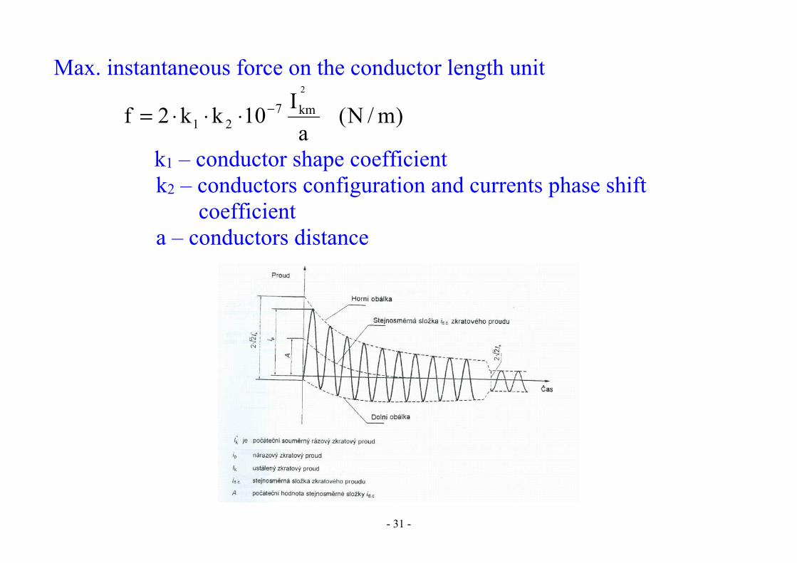
Max. instantaneous force on the conductor length unit
)m/N(a
I10kk2f2
km721
−⋅⋅⋅= k1 – conductor shape coefficient
k2 – conductors configuration and currents phase shift coefficient
a – conductors distance
- 32 -
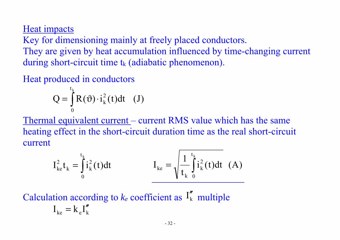
Heat impacts Key for dimensioning mainly at freely placed conductors. They are given by heat accumulation influenced by time-changing current during short-circuit time tk (adiabatic phenomenon).
Heat produced in conductors
)J(dt)t(i)(RQkt
0
2k ⋅ϑ=
Thermal equivalent current – current RMS value which has the same heating effect in the short-circuit duration time as the real short-circuit current
=kt
0
2kk
2ke dt)t(itI
)A(dt)t(it1I
kt
0
2k
kke =
Calculation according to ke coefficient as kI ′′ multiple keke IkI ′′=

- 33 -
Ground fault in three-phase systems
MV grids without a directly grounded neutral point (distribution systems) → single-phase ground fault has a different character than short-circuits (small capacitive current).
Fault current proportional to the system extent. A5Ip > → arc formation → conductors, towers, insulators burning →
→ 2ph, 3ph short-circuits (mainly at cables)
GF compensation → uninterrupted system operation (until the failure clearance, short supply break), arc self-extinguishing
Ground fault • resistive (100x Ω), metal and arc (x Ω)
- 34 -
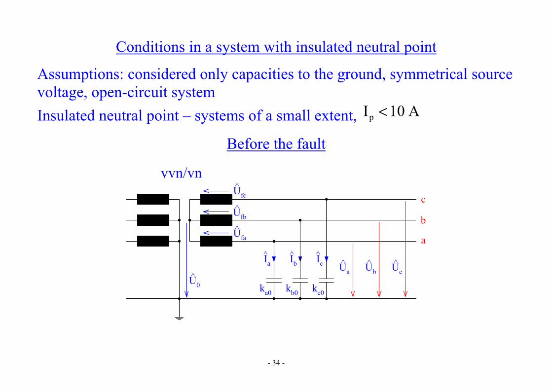
Conditions in a system with insulated neutral point
Assumptions: considered only capacities to the ground, symmetrical source voltage, open-circuit system Insulated neutral point – systems of a small extent, A10Ip <
Before the fault
c
b
a
Ua^ Ub
^ Uc^
ka0 kb0 kc0
Ia^ Ib
^ Ic^
Ufc^
Ufb^
Ufa^
vvn/vn
U0^

- 35 -
0UUU c,b,fa0c,b,a =−− c,b,a0c,b,ac,b,a UkjI ω=
System with insulated neutral point 0III cba =++
Symmetrical source fafcfa
2fb UaU,UaU ==
Neutral point voltage
fa0c0b0a
0c0b2
0a0 U
kkkkakakU
++++−=
Unbalanced capacities 0U0 ≠ Symmetrical capacities 0Ukkkk 000c0b0a ====
- 36 -
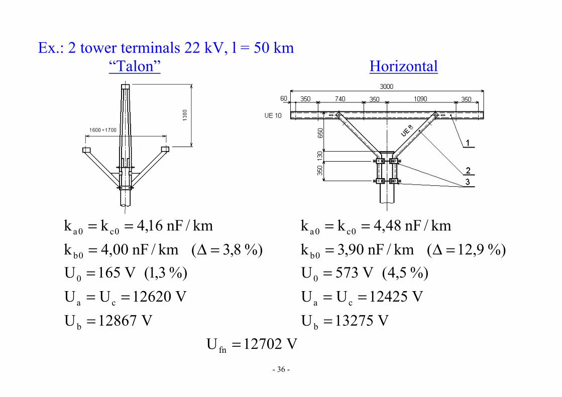
Ex.: 2 tower terminals 22 kV, l = 50 km “Talon” Horizontal
%)8,3(km/nF00,4kkm/nF16,4kk
0b
0c0a
=Δ===
%)9,12(km/nF90,3kkm/nF48,4kk
0b
0c0a
=Δ===
V12867UV12620UU
%)3,1(V165U
b
ca
0
===
=
V13275UV12425UU%)5,4(V573U
b
ca
0
===
=
V12702Ufn =
- 37 -
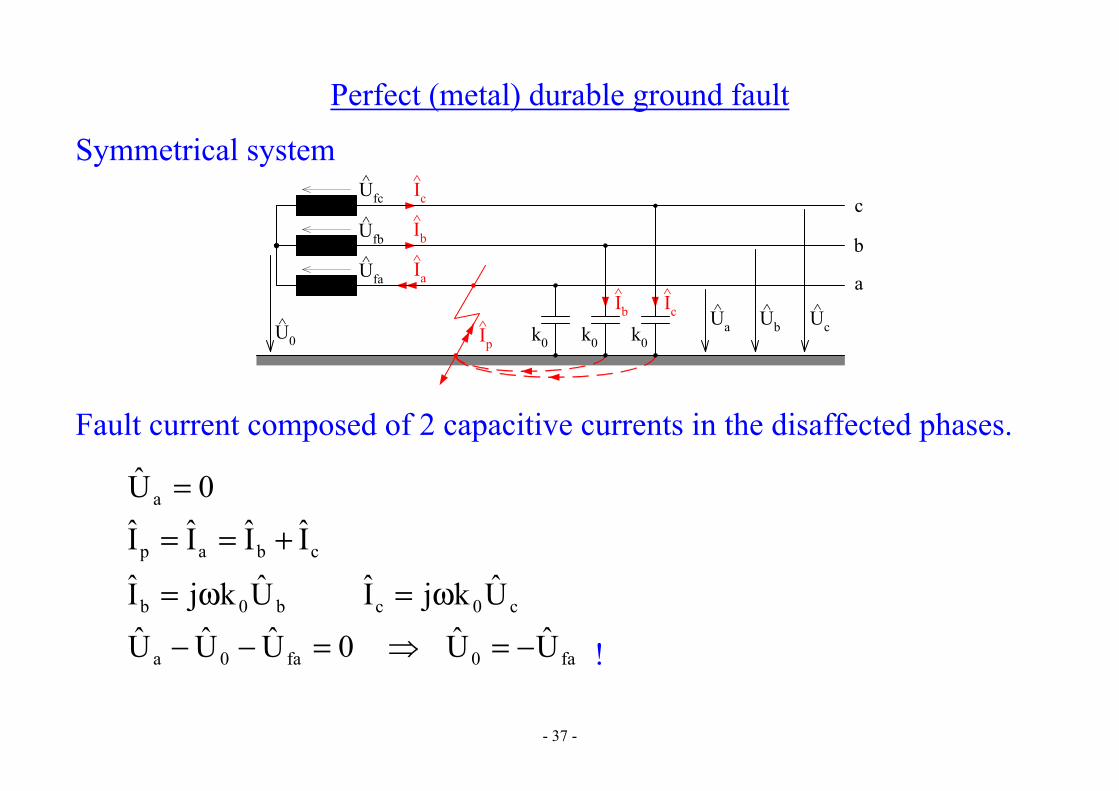
Perfect (metal) durable ground fault
Symmetrical system c
b
a
Ua^ Ub
^ Uc^
k0 k0 k0
Ia^
Ib^
Ic^Ufc
^
Ufb^
Ufa^
U0^
Ic^Ib
^
Ip^
Fault current composed of 2 capacitive currents in the disaffected phases.
0Ua =
cbap IIII +==
b0b UkjI ω= c0c UkjI ω=
fa0fa0a UU0UUU −==−− !

- 38 -
( ) fa30j
fa2
fb0bfb0b Ue3Ua1UUU0UUU
−=+−=+==−− ! ( ) fa
30jfafc0cfc0c Ue3Ua1UUU0UUU
−−=+−=+==−− !
→ affected phase voltage – zero neutral point voltage – phase-to-ground value disaffected phases voltage – phase-to-phase value
Ground fault current ( )cb0cbp UUkjIII +ω=+= ( ) ( )[ ] fa
20 Ua1a1kj +−++−ω= ( ) fa
20 U11aa2kj −+++−ω=
( )V,F,s;AUkj3Ukj3I 100fa0p
−ω=ω−=
- 39 -
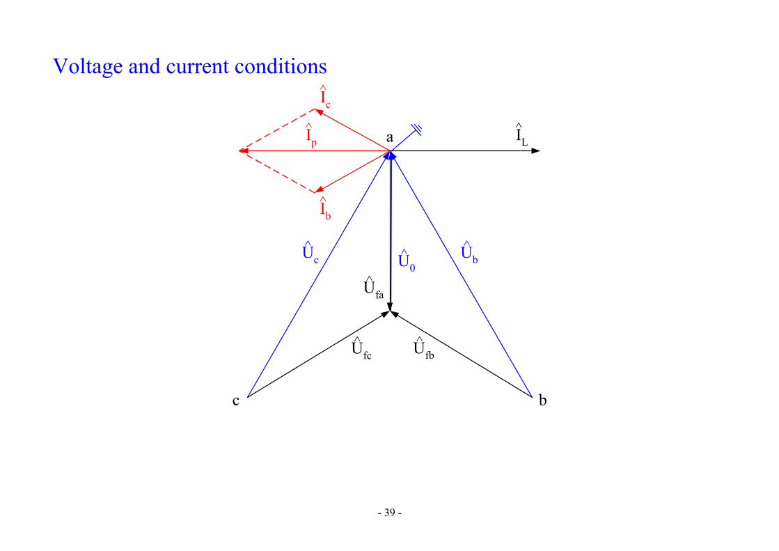
Voltage and current conditions
U0^ Ub
^Uc^
Ufa^
Ufb^Ufc
^
c b
aIp^
Ic^
Ib^
IL^

- 40 -
Fault current depends on the total system extent and almost doesn’t depend on the fault point distance from the transformer.
( )V,km,km/F,s;AlUk3I 1f01p
−ω=
Ip^
Ip^
- 41 -
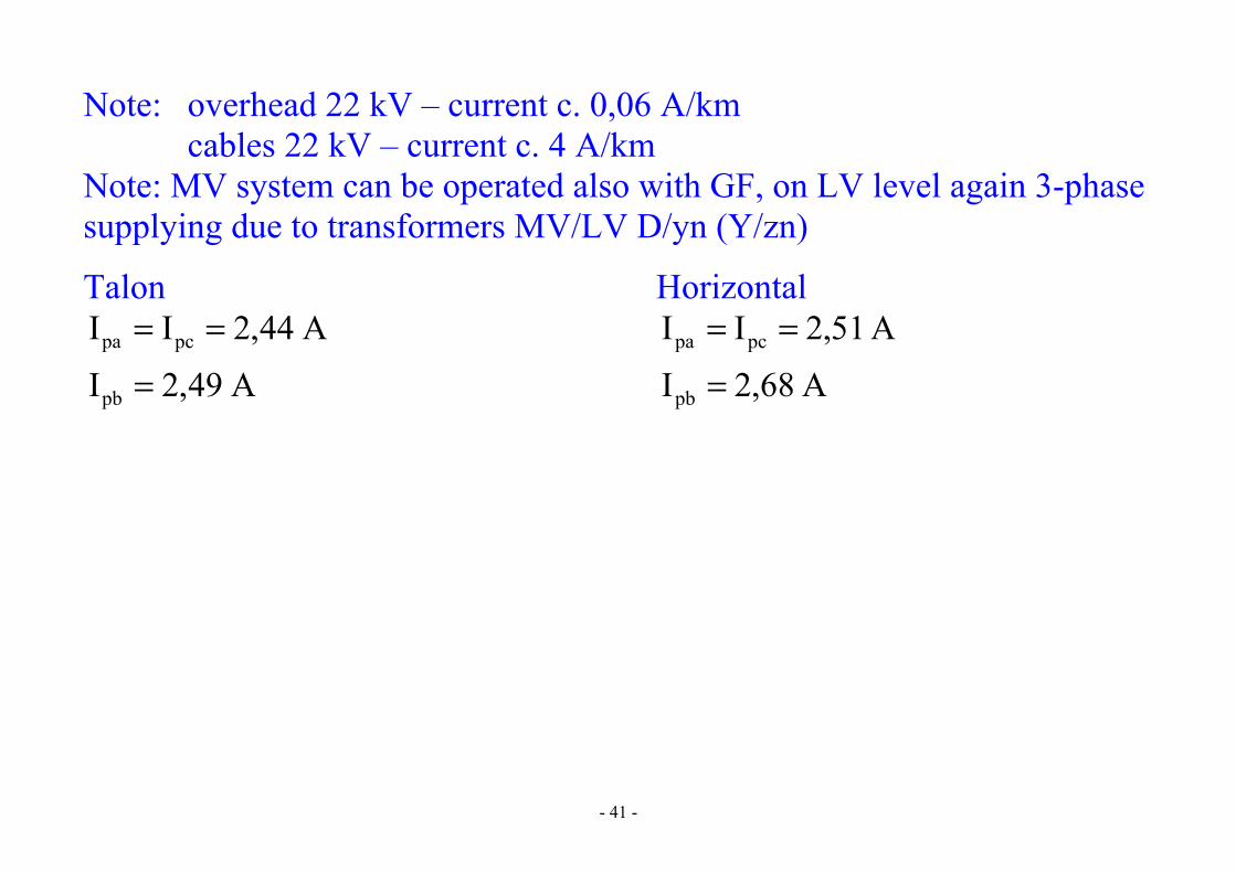
Note: overhead 22 kV – current c. 0,06 A/km cables 22 kV – current c. 4 A/km Note: MV system can be operated also with GF, on LV level again 3-phase supplying due to transformers MV/LV D/yn (Y/zn)
Talon Horizontal
A49,2I
A44,2II
pb
pcpa
=
== A68,2I
A51,2II
pb
pcpa
=
==

- 42 -
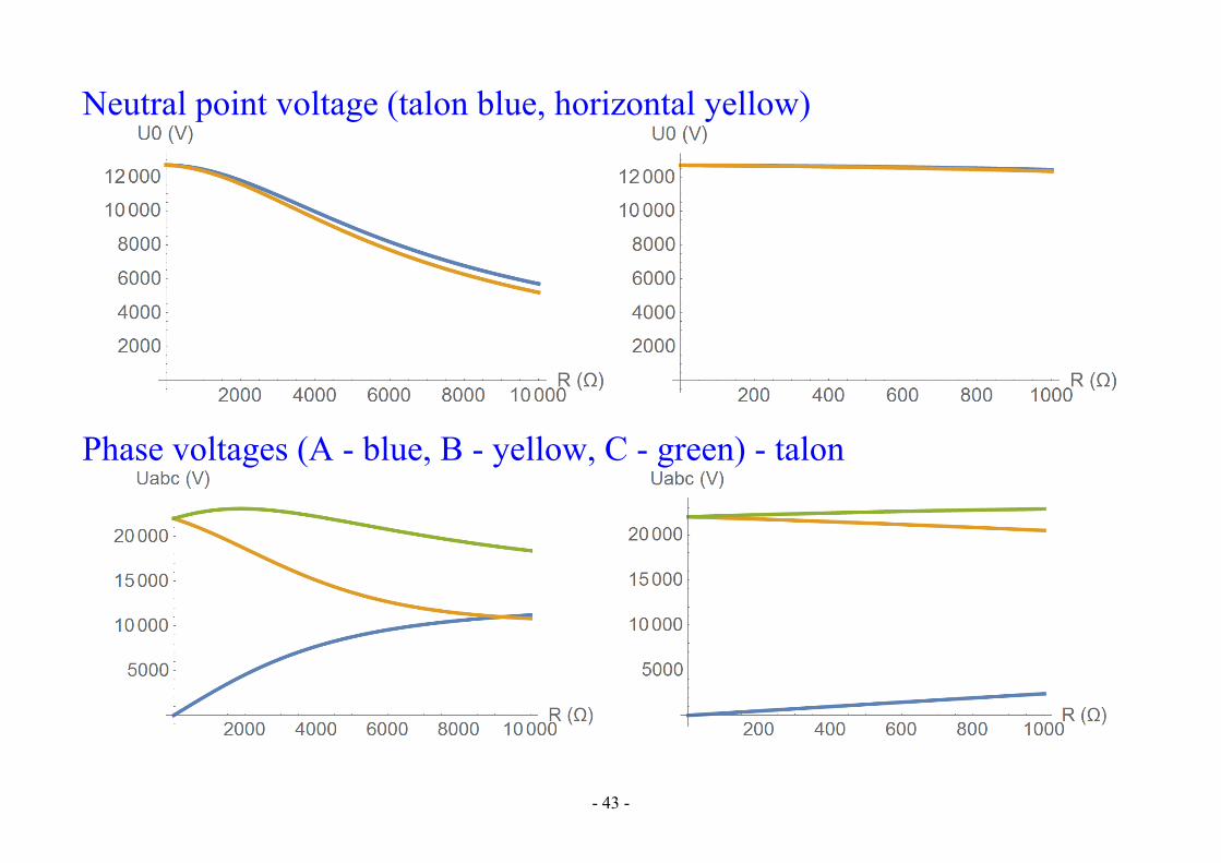
Resistive ground fault
c
b
a
Ua^ Ub
^ Uc^
k0 k0 k0
Ip-Ia^
Ib^
Ic^Ufc
^
Ufb^
Ufa^
U0^
Ic^Ib
^Ip^ Ia
^
^
Rp
Affected phase voltage non-zero
cbapap IIIR/UI ++=−= Neutral point voltage
( )( ) fa1
p0c0b0a
1p0c0b
20a
0 URkkkj
RkakakjU −
−
+++ω+++ω
−=
0R p = fa0 UU −= ∞=pR 0U0 = (for symmetrical capacities)
- 43 -
Neutral point voltage (talon blue, horizontal yellow)
Phase voltages (A - blue, B - yellow, C - green) - talon
- 44 -
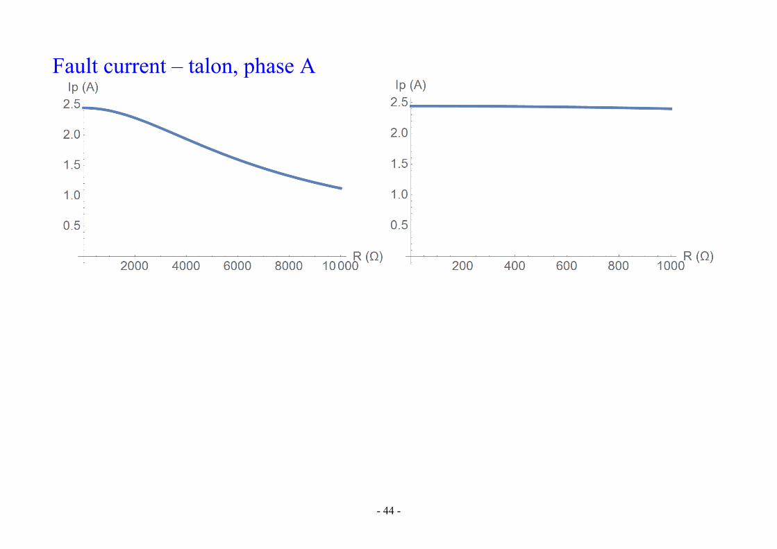
Fault current – talon, phase A

- 45 -
Ground fault current compensation
Compensation in systems where A5Ip > - suitable A10Ip > - necessary Method: continuously controlled arc-suppression coil (Petersen coil) between the transformer neutral point and the ground (in case of transformers with D winding by means of grounding transformer with Zn, Yn – artificial neutral point)
c
b
a
U0^
k0 k0 k0Ip^
L
IL^
IL^
Ib^ Ic
^
Ib^
Ic^
Ia^
- 46 -
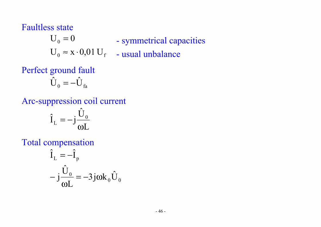
Faultless state 0U0 = - symmetrical capacities f0 U01,0xU ⋅≈ - usual unbalance
Perfect ground fault fa0 UU −=
Arc-suppression coil current
LUjI 0
L ω−=
Total compensation
pL II −=
000 Ukj3L
Uj ω−=ω
−
- 47 -
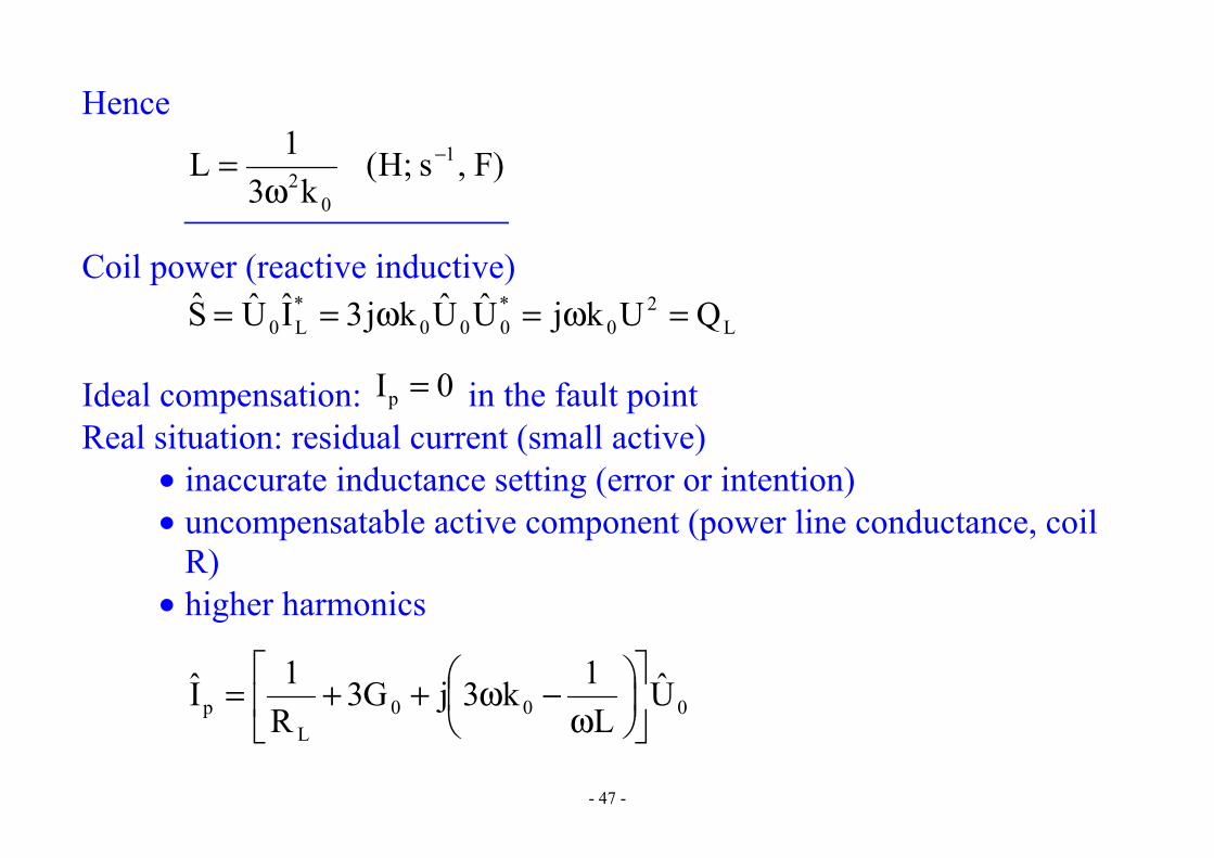
Hence
)F,s;H(k3
1L 1
02
−
ω=
Coil power (reactive inductive) L
20
*000
*L0 QUkjUUkj3IUS =ω=ω==
Ideal compensation: 0Ip = in the fault point Real situation: residual current (small active)
• inaccurate inductance setting (error or intention) • uncompensatable active component (power line conductance, coil
R) • higher harmonics
000L
p UL
1k3jG3R1I
ω−ω++=

- 48 -
U0^ Ub
^Uc^
Ufa^
Ufb^Ufc
^
c b
a
Ip^
Ib+Ic^^ IL
^
ILL^
ILR^
- 49 -
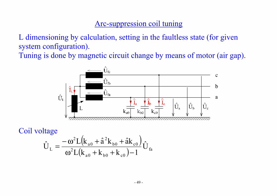
Arc-suppression coil tuning
L dimensioning by calculation, setting in the faultless state (for given system configuration). Tuning is done by magnetic circuit change by means of motor (air gap).
Coil voltage ( )
( ) fa0c0b0a
20c0b
20a
2
L U1kkkL
kakakLU−++ω
++ω−=

- 50 -
Resonance dependence
( )LfUU
fa
L = ( )0c0b0a2REZ kkk
1L++ω
=
L (H)LREZ
CABLE
OHL
ΔL
UL
Ufa
∼ΔU
0
- 51 -
Overhead power lines • higher capacitive unbalance • maximum limited by resistances • LREZ compensates GF totally → resonance coil • setting by UL measurement • with small R the transformer neutral point is strained too much in
resonance → intended (small) detuning → dissonance coil
Cable power lines • small capacitive unbalance → flat curve → difficult tuning
- 52 -

- 53 -
Neutral point voltage (talon blue, horizontal violet)
talon H45,16LREZ = horizontal H76,15LREZ =

- 54 -
Fault current for coil detuning (talon blue, horizontal violet)
phase A phase B
- 55 -
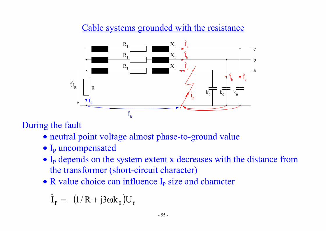
Cable systems grounded with the resistance
c
b
a
UR^
k0 k0 k0Ip^
R
IR^
IR^
Ib^ Ic
^
Ic^
Ib^
Ia^
R1
R1
R1
X1
X1
X1
During the fault
• neutral point voltage almost phase-to-ground value • Ip uncompensated • Ip depends on the system extent x decreases with the distance from
the transformer (short-circuit character) • R value choice can influence Ip size and character
( ) f0P Uk3jR/1I ω+−=
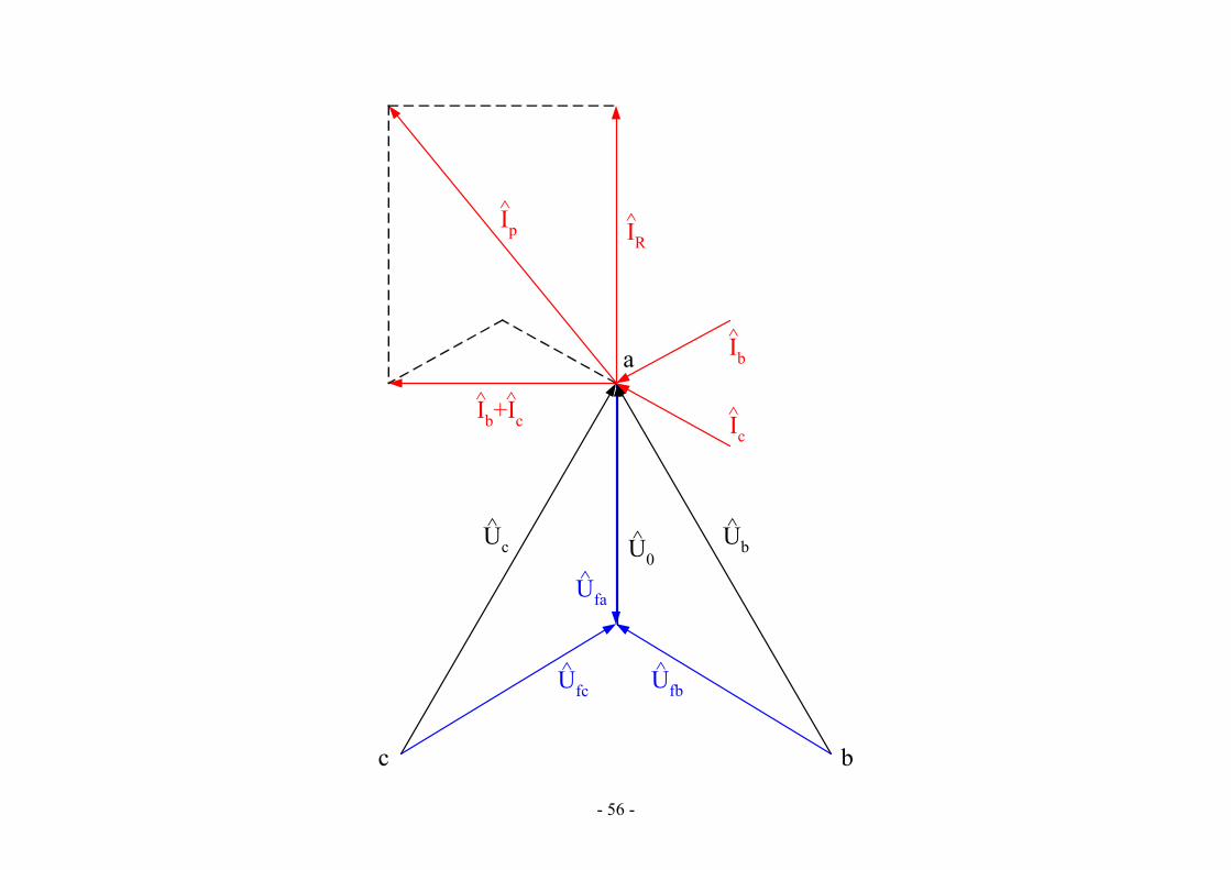
- 56 -
U0^ Ub
^Uc^
Ufa^
Ufb^Ufc
^
c b
a
Ip^
Ib^
Ic^Ib+Ic
^
IR^
^
- 57 -
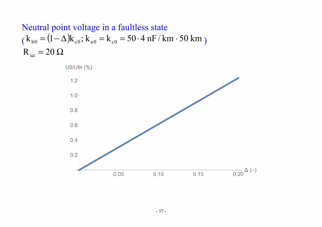
Neutral point voltage in a faultless state ( ( ) km50km/nF450kk;k1k 0c0a0c0b ⋅⋅==Δ−= )
Ω= 20R uz