shore protection guidelinesepsmg.jkr.gov.my/images/7/7d/shore_protection_guidelines.pdf · jabatan...
TRANSCRIPT
SHO
CAWA
JABATAN KERJA RAYA MALAYSIA
Shore Protection
Shoreline Processes The erosion Problem
Shore Protection Structures
Bulkheads & Seawalls Revetments
Gabions Groins
Beach Fills Vegetation
Infiltration & Drainage Controls Slope Flattening
Perched Beach Geotextiles
Selection of structures
Breakwater
Function of Breakwater Types of Breakwater
Design Guidelines Construction of breakwater
Coastal & hydraulic Study
Module of Analysis Computer Software of Analysis
Checklist of Hydraulic Study
RE PROTECTION GUIDELINES
UNIT MARITIM NGAN PANGKALAN UDARA DAN MARITIM
IBU PEJABAT JKR MALAYSIA KUALA LUMPUR

Maritime Unit Shore Protection Guidelines
Page
CONTENT i
CHAPTER 1 INTRODUCTION 1
1.0 Objectives
1.1 Shoreline Processes
1.1.1 Wave Action
1.1.2 Sediment Transport
1.1.3 Current
1.1.4 Seasonal Change
1.1.5 Water level Variations
1.1.5.1 Astronomical Tides
1.1.5.2 Storm Effects
1.2 Erosion Problem
1.2.1 Importance of Shoreform
1.2.1.1 Bluff and Cliff Shorelines
1.2.1.2 Low Erodible Plains and Sand
Beaches
1.2.1.3 Wetlands
1.2.2 The Causes of Erosion
1.2.2.1 Wave Action
1.2.2.2 Littoral Material Supply
1.2.2.3 Wind
1.2.3 The Effects of Erosion
1
1
1
3
5
5
5
5
7
7
7
8
9
10
10
10
10
11
11
CHAPTER 2 SHORE PROTECTION STRUCTURES 12
2.0 Available Option
2.1 Bulkheand and Seawalls
2.2 Revetments
2.2.1 Stone Revetments
12
13
14
16
i

Maritime Unit Shore Protection Guidelines
2.2.1.1 Rubble Revetments
2.2.1.2 Qarrystone
2.2.1.3 Concrete Revetments
2.2.1.4 Concrete Block Revetments
2.2.1.5 Concrete Masonry Blocks
2.2.2 Stacked Bag or Mat Revetments
2.2.3 Riprap Revetments
2.3 Gabions
2.4 Groins
2.5 Beach Fills
2.6 Vegetation
2.7 Infiltration and Drainage Controls
2.8 Slope Flattening
2.9 Perched Beach
2.10 Structures and Fills
2.11 Structures and Vegetations
2.12 Geotextiles in Coastal Protection
2.12.1 Geotextile filters
2.12.2 Riprap Protection
2.12.3 Concrete Block Protection
2.14.4 Gabion Mattress Protection
2.13 Selection Among Available options
2.13.1 Shoreform Compatibility
2.13.1.1 Bluff Shorelines
2.13.1.2 Sand Beaches or Low Plains
2.13.2 Effects On Coastal Processes And Adjacent
Properties
2.13.3 Effects on Shoreline Uses
2.13.4 Effects on the Environment
2.13.5 Implications for Coastal Zone Management
2.13.5.1Bluff Shorelines
2.13.5.2Beach Shorelines
2.13.5.3Wetlands and Marshes
16
17
17
17
18
18
19
20
21
23
24
25
26
26
27
27
27
28
28
31
32
32
32
32
33
33
34
36
37
37
38
39
ii

Maritime Unit Shore Protection Guidelines
2.14 Glossary
2.15 References
APPENDIX
39
47
48
CHAPTER 3 SHORE PROTECTION: BREAKWATER 49
3.0 Introduction
3.1 Function
3.2 Types of Breakwater
3.3 Example of Types of Breakwater
3.4 Design Guidelines
3.4.1 Principle of Design
3.4.2 Layout of Breakwater
3.4.3 Influence of Breakwaters on Site Selection
3.4.4 Design Conditions and Parameters
3.4.5 Phases (Work Flow)
3.5 Design of a Rubble Mound Breakwater
3.5.1 Alignment
3.5.2 Cross Section
3.6 Typical Rubble Mound Breakwaters
3.7 Construction
3.8 Reference
APPENDIX
49
49
50
52
53
53
53
53
55
55
56
56
56
63
64
65
66
CHAPTER 4 COASTAL AND HYDRAULIC STUDY 67
4.0 Pengenalan
4.1 Objectives Kajian Hidraulik
4.2 Senarai Module
4.3 Senarai Model Komputer
4.3.1 Short Description of the Numerical Model
MIKE 21
4.3.2 List of Model MIKE 21
4.3.3 Methodology of MIKE 21 Modeling Works
4.4 Arrangement of Report
67
68
68
68
70
71
72
72
iii
Maritime Unit Shore Protection Guidelines
4.5 Senarai Semakan Bagi Kajian Hidraulik
4.5.1 Input Data
4.5.2 Penentukuran
4.5.3 Verifikasi
4.5.4 Pelaksanaan Model
4.5.5 Rumusan dan Cadangan
4.6 References
APPENDIX
73
73
74
75
75
76
76
77
iv
Maritime Unit Shore Protection: Introduction
CHAPTER 1
SHORE PROTECTION: INTRODUCTION 1.0 OBJECTIVES
This database is intended for planning, regulatory, and etc for local government officials whose duties include some involvement in shoreline erosion prevention measures. The discussion is limit to the shorelines of sheltered waters that are not subject to the direct action of undiminished oceanic waves.
The erosion problems that are experienced today are often caused by failure to
recognize that shorelines have the areas of continuous and sometimes dramatic change. This lack understanding of shoreline processes has been catastrophic for both private and public. The objective of the report is to show that the situation is not without remedies and large variety of reasonably low cost alternatives are available Therefore before any action is taken, it is important to recognize and understand the natural forces at work in the general area of a propos project. By considering the overall view rather than condition just at the site, a broader perspective of the problem and possible solutions is developed, and a more informed decision can be made.
The database is aimed to slow or arrest erosion problems. However, successful use of
the material presented depends on numerous factors that are peculiar to individual situations. 1.1 SHORELINE PROCESSES
The first requirement in solving an erosion problem or reviewing a proposed solution is to understand the processes and forces at work. Without such basic knowledge, any solutions are likely to be misguided and inappropriate. The following presents basic information about shoreline processes as a foundation for the subsequent discussion. 1.1.1 Wave Action
While waves are always present on the open coast, they are not continuously active in sheltered waters. Nonetheless, they are still the major cause of erosion in all coastal areas. Understanding how wave action influences shoreline processes requires familiarity with several basic characteristics of waves: height, period, and length (Figure 1.1). Wave height is
1

Maritime Unit Shore Protection: Introduction
the vertical distance between the wave crest and trough. Wave period is the time it takes two successive wave crests to pass a stationary point, and wavelength is the distance between successive crests.
As a wave moves through deep water (depths greater than one half the wavelength),
these basic characteristics do not change. When a wave approaches shallower water near the shore, the period remains constant, the forward speed and wavelength decrease, and the height slightly increases. The wave begins to feel the “bottom", and its profile steepens as its gently rolling shape sharpens to a series of pointed crests with intervening flat troughs. When the wave height is about 80 percent of the water depth, the wave can no longer steepen and it breaks. For example, a 5-foot wave breaks in a water depth of about 6.5 feet.
Important wave properties are demonstrated when a series of regular waves meet a
solid barrier, such as a breakwater (Figure 1.2). Wave diffraction occurs when the waves pass the barrier, and part of their energy is transferred along the crests to the quiet area in the shadow of the structure. Diffraction causes waves to form in the shadow zone that are smaller than waves in the adjacent unprotected zones.
Wave reflection occurs on the offshore side of the breakwater. While waves passing
the structure are diffracted, the portions striking the breakwater are reflected like a billiard ball from a cushion. If the structure is a smooth vertical wall, the reflection is nearly perfect, and if the wave crests are parallel with the breakwater, the reflected and incoming waves will reinforce each other to form standing waves, which are twice as high as the incoming waves. These can cause considerable scouring of the bottom. If the waves approach at an angle, no standing waves form, but the resulting sea-state is choppy because the reflected waves cross the path of incoming waves. This could also contribute to bottom scour.
The final important wave characteristic is evident when waves break either on a beach
or structure. The uprush of water after breaking is called runup and it expends the wave’s remaining energy. The runup height depends on the roughness and steepness of the structure or beach and the characteristics of the wave.
Figure 1.1: Characteristic of Waves
2

Maritime Unit Shore Protection: Introduction
The wave generation process depends on several important factors, the most
prominent being wind, although the movements of pleasure craft and large vessels are also significant sources of wave activity. The height of wind-driven waves depends on the wind speed, duration, fetch length, and water depth. Wind speed is obviously important, but duration (length of time the wind blows) must also be considered because wind action must be sustained for wave growth. Fetch is the over-water distance wind travels while generating waves. At a given site, the maximum fetch length, or longest over-water distance, is generally the most important. Less important, but still critical, is the average water depth along the fetch. Deeper water allows for somewhat larger waves because of decreased bottom friction.
Figure 1.2: wave Diffraction and Reflection
1.1.2 Sediment Transport
The large variety of shoreline materials ranges from rock cliffs to boulders, cobbles, gravel, sand, silt, and clays. Geologists and engineers have developed several classification systems for these materials and an example is given in Table 1.1.
Table 1.1: Classification of Shoreline Materials
Particle Size Range Size Description (Inches) (mm) Boulder greater than 10 greater than 256 Cobble 10 – 3 256 - 76 Gravel 3 - 0.18 76 – 4.8 Sand 0.18 - 0.003 4.8 -0.07 Silt 0.003 - 0.00015 0.07 -0.004 Clay smaller than 0.00015 smaller than 0.004
3
Maritime Unit Shore Protection: Introduction
Littoral (shoreline) materials are derived from the deterioration and erosion of coastal bluffs and cliffs; the weathering of rock materials found inland and transported to the shore by rivers and streams; the disintegration of shells, coral or algae and the production of organic material (generally peat) by coastal wetlands.
Failure or erosion of a bluff causes material to be deposited at the base. Waves sort
this material and carry the fine-grained silts and clays far offshore where they settle to the bottom. The original deposit is eventually reduced to sand and gravel, which form a beach. If no other littoral material is carried to the sit by waves, even the sand and fine gravel will eventually disappear down the coast or offshore, leaving only coarse gravel behind However, a new supply of material may be deposited on the beach by a fresh failure of the bluff, and the process begins again. In most cases, littoral materials comprising beaches are derived from erosion of the shoreline itself.
Rivers and streams carry sediments eroded from mountain forests, and fields,
particularly during floods. The sediments are usually smaller than sand because the coarser particles are not easily transported by the streams. Except where streams traverse sand drainage basins, the contribution to beach building from this source is usually smaller than from the first source.
Coral reefs, shells, and other plant or animal matter are another material source. They
gradually break and weather in carbonate particles, which are, for instance, the primary component of beaches south of Palm Beach, Florida. Swamps, marshes, a coastal wetlands produce peats and other organic matter. Too light to remain in place under continued wave action, they are ultimately washed offshore unless stabilized.
Littoral materials are transported along the shore by wave action. As waves approach
the shore, they move to progressive shallower water where they bend or refract until finally breaking at an angle to the beach. The broken wave creates considerable turbulence, lifting bottom materials into suspension and carrying them up the beach face in the general direction of wave approach. A short distance up the beach, the motion reverses direction back down the beach slope. In this case, the downrush does not follow the path of the advancing wave but instead, moves down the slope in response to gravity. The next wave again carries the material upslope, repeating the process, so that each advancing wave and the resulting downrush move material along the beach in the downdrift direction. As long as waves approach from the same direction, the alongshore transport direction remains the same.
Littoral materials are also moved by the longshore current. Arising from the action of
breaking waves, this current is generally too weak, alone, to move sand. However, the turbulence of breaking wave’s places sand temporarily in suspension and permits the longshore current to carry it downdrift. The sand generally settles out again within a short distance, but the next wave provides the necessary turbulence for additional movement. The downdrift movement of material is thus caused by zigzag motion up and down the beach, and the turbulence and action of the wave-generated longshore current.
4

Maritime Unit Shore Protection: Introduction
1.1.3 Currents
The water at the shore is constantly in motion due to currents as well as waves. Tides produce currents in sheltered bays connected to the open sea. As the tide begins to rise in the ocean (flood tide), the bay's water surface elevation lags behind, generating a current into the bay. As the tide falls (ebbs), the ocean surface drops more quickly so that the bay surface becomes higher and current flows out of the bay. Tidal currents are generally not strong enough to cause erosion problems except in the throat area of tidal inlets connecting bays to the ocean. 1.1.4 Seasonal Change
The most notable seasonal change at sheltered sites is the frequency, direction, and severity of high winds. Storms generate strong winds that often approach from entirely different directions than winter squalls. The manners in which storm winds align with fetch lengths at the site figures prominently in evaluating the potential for wave damage. If the most severe winds striking a site are generally along the longest fetch length, structures should be built more strongly than if severe winds rarely approach from that direction.
1.1.5 Water Level Variations
The water surface elevation itself constantly changes with time. The Stillwater level, the water level with no waves present, changes because of astronomical tides and storms.
1.1.5.1 Astronomical Tides
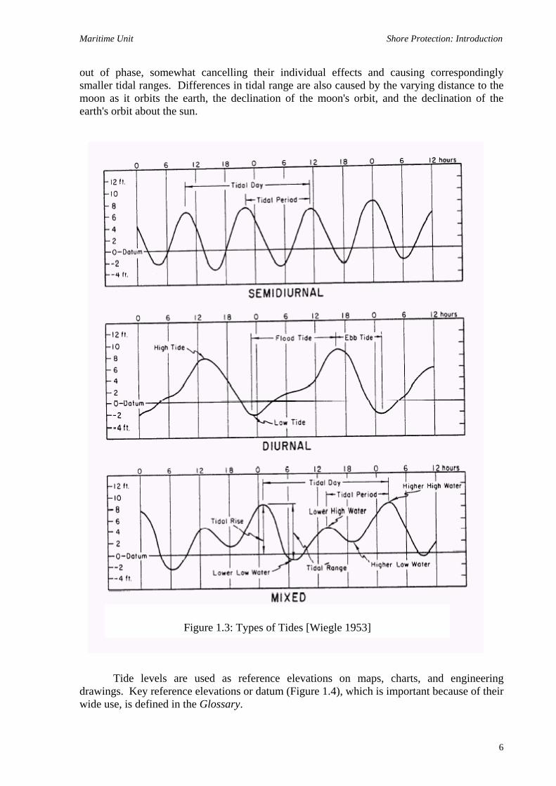
Tides are caused by the gravitational attraction between the earth, moon, and sun, and are classified as diurnal, semidiurnal, or mixed. Diurnal tides have only one high and low each day. Semidiurnal tides have two approximately equal highs and two approximately equal lows daily. Mixed tides, on the other hand, exhibit a distinct difference in the elevation of either the two successive highs or two successive lows. In addition, at locations with mixed tides, the characteristics of the tide may change to diurnal or semidiurnal at certain times during the lunar month (Figure 1.3).
In addition, the tidal range, or difference between the high and low, tends to fluctuate
throughout the lunar month. Spring tides have larger than average ranges with higher high and lower low tides. Neap tides are exactly opposite with smaller ranges, lower highs, and higher lows. Spring tides occur with full and new moons because the gravitational attraction of both the sun and moon act along the same line, tending to exaggerate the difference between the high and low tides. At neap tides (during quarter moons), the pull of the sun and moon are
5
Maritime Unit Shore Protection: Introduction
out of phase, somewhat cancelling their individual effects and causing correspondingly smaller tidal ranges. Differences in tidal range are also caused by the varying distance to the moon as it orbits the earth, the declination of the moon's orbit, and the declination of the earth's orbit about the sun.
Tide levels are used as reference elevations on maps, charts, and engineering
drawings. Key reference elevations or datum (Figure 1.4), which is important because of their wide use, is defined in the Glossary.
Figure 1.3: Types of Tides [Wiegle 1953]
6

Maritime Unit Shore Protection: Introduction
Figure 1.4: Illustration of Tides Datums [After Harris 1981]
1.1.5.2 Storm Effects
Storms tend to increase the stillwater level because of atmospheric pressure differences, high winds, and the effects of large breaking waves. Atmospheric pressure differences across a large water body can commonly cause one or two foot rises in the water level in the lower pressure area. The stress on the water surface from high storm winds also tends to drive the water on shore to above normal levels (storm setup) until balanced by the tendency for the water to flow back to a lower level. These high winds also generate large waves, which tend to pile water on shore as they break, raising the stillwater level further.
Enclosed water bodies can also respond to storm forces by seiching. This occurs when
storm winds drive the water surface higher at the downwind end of a lake. As the storm passes, this pent-up water is released, causing it to move toward the opposite end of the lake, resulting in oscillations. This back and forth movement (seiching) will noticeably continue for several cycles. 1.2 EROSION PROBLEM 1.2.1 Importance of Shoreform
The land-sea boundary is characterized by many shapes and configurations. Geologists
have devised elaborate classification systems to describe these various features. For the purpose of understanding basic shoreline processes and for designing appropriate corrective measures, however it will only be necessary to informally classify shorelines as either bluffs, low erodible plains (including sandy beaches), or wetlands. Many shorelines, of course contain two or even all three basic features. For instance, a shoreline may be a high bluff with a sand beach at the base, or a gently sloping plain -fronted by a marsh. In that case, one must consider the interaction of these features with the erosive forces and then single out the most important for further study.
7

Maritime Unit Shore Protection: Introduction
1.2.1.1 Bluff and Cliff Shorelines
Cliff shorelines consist primarily of resistant rock. On the other hand, bluff shorelines are composed of such sediments as clays, sands and gravels, or erodible rock. Cliffs rarely suffer severe or sudden erosion but undergo slow, steady retreat under wave action over a long period.
Erosion problems are most common along bluff shorelines where a variety of forces
and processes act together. The most prevalent causes of bluff erosion and recession are scour at the toe (base) by waves and instability of the bluff materials themselves. Slope stability problems are highly technical and can only be analyzed correctly using methods of geotechnical engineering. Therefore, they are beyond the scope of this report. A brief discussion of factors affecting slope stability and how to recognize potential problems is presented below. It is suggested that if there are slope stability problem, a registered professional geotechnical engineer should be contacted.
Soils are not generally stable at a vertical face, but form a slope that varies with the
soil and groundwater conditions. This slope forms as a result of a series of failures whose nature depends on whether the soil is cohesive (clay) or granular (sand, silt, gravel, etc.). Cohesive soils generally slide along a circular or curved arc, the soil moving downward as it rotates along the failure surface. Granular soils, on the other hand, fail when vertical-sided blocks drop to the bottom or when the soil suddenly flows down an inclined plane. Height is a factor because high bluffs (over 20 feet) impose greater stresses and are likely to suffer more severe stability problems than low bluffs. The internal strength of soils can be decreased by groundwater and seepage flows within the bluff. For instance, rainwater is naturally absorbed and seeps down to lower levels. Soils, such as coarse sand, which allow rapid and free passage of water, are permeable. On the other hand, impermeable soils, such as clay, do not allow the free flow of water except through cracks or other openings. The large tree's roots penetrate the clay layer and provide a path for seepage to the sand layer beneath. Likewise, as the clay fails, cracks form at the surface which provides a path for seepage to penetrate the soil, further weaken it, and accelerate the failure process. Water can also enter the clay along the existing circular failure surface, leading to further movement.
Once seepage penetrates the clay and reaches the permeable sand layer, it passes
freely to the lower clay layer where it flows along the clay's surface and exits the bluff face. This seepage can increase the risk of slope failure. In addition, surface runoff can erode the bluff face, causing gullies and deposits of eroded material on the beach below. The seepage exiting the bluff at the clay layer can also cause surface erosion.
The added weight or loading of buildings and other structures can increase soil
stresses and contribute to slope failure. Structures located near the top edge of the bluff have the greatest impact. An in-ground pool, even when filled, weighs less than the soil it replaces and would not adversely affect stability, provided no leakage exists and splashing is minimized.
The other major cause of bluff shoreline problems is wave action at the toe. Waves
move clays and silts offshore while leaving sands and gravels for the beach. During storms, however, waves can reach the bluff itself and erode or undercut the toe. Depending on the
8

Maritime Unit Shore Protection: Introduction
bluff soil characteristics, only a short time may be needed under such conditions for the entire bluff face to fail.
The slope of the offshore bottom is important to wave action on a bluff. If the
offshore slopes are steep, deep water is closer to shore, more severe wave activity is possible, and maintenance of a protective beach is more difficult. Flat offshore slopes, on the other hand, result in shallower water near the shoreline, which inhibits heavy wave action at the bluff and provides for potentially better protective beaches. 1.2.1.2 Low Erodible Plains and Sand Beaches
Beaches and erodible plains are composed of loose sediments ranging from silts to gravel that slope gently up and away from the water's edge. Because they seldom reach more than five to ten feet above Stillwater level, such shorelines are susceptible to flooding as well as erosion. Erosion problems are caused by wave action, although wind can be important in some cases.
Figure 1.5 depicts an idealized beach profile. Waves approach from offshore, finally
breaking and surging up the foreshore. At the crest, the profile flattens considerably, forming a broad berm inaccessible to normal wave activity. The beach berm is often backed by a low scarp formed by storm waves, a second berm, and eventually a bluff or dune.
During periods of either increased water levels or wave heights, the sand above the
low water level is eroded, carried offshore, and deposited in a bar. Eventually, enough sand collects to effectively decrease the depths and cause the storm waves to break farther offshore. This reduces wave action on the beach, and helps re-establish equilibrium. At open coast sites, the process eventually reverses, and long-period swells again return the sand to the beach after storms. At sheltered sites where no exposure to oceanic swells exists, the recovery does not occur, and storm caused erosion becomes permanent.
Figure 1.5: An Idealized Beach Profiles [After U.S. Army Corps of Engineers 1977c]
9
Maritime Unit Shore Protection: Introduction
1.2.1.3 Wetlands
Wetlands usually occur in combination with sand beaches or low erodible plains. Wetlands are defined as:
Those areas that are inundated or saturated by surface or groundwater at a frequency
and duration sufficient to support, and that under normal circumstances do support, a prevalence of vegetation typically adapted for life in saturated soil conditions. Wetlands generally include swamps, marshes, bogs, and similar areas" [U.S. Army Corps of Engineers (1977b).
Marsh plants are primarily herbaceous (lacking woody stems), such as grasses, sedges,
and rushes. The species present depend on location and whether the marsh is low (regularly flooded) or high (irregularly flooded).
Until recently, wetlands were regularly drained and filled for new development or
agriculture. They are now recognized as a vital link in the food chain of the aquatic community and for their capacity to absorb water-borne pollutants. However, more importantly, they provide shore protection by absorbing energy of approaching waves and trapping sediment carried along by currents.
The shore protection qualities of wetlands are particularly important when they
provide a buffer zone in front of a sandy beach or other area vulnerable to erosion. While not providing full protection, they effectively diminish wave energy and allow for less massive and costly backup protection. 1.2.2 The Causes of Erosion 1.2.2.1 Wave Action
Wave action is the most obvious cause of erosion. 1.2.2.2 Littoral Material Supply
Waves keep the littoral materials constantly moving downdrift. As long as equal quantities of material are transported from the updrift direction, the shoreline remains stable. When the updrift supply exceeds the amount moving downdrift, the shoreline accretes (material accumulates). However, when the updrift supply is deficient, the shoreline retreats.
Much of the littoral material supplied to shorelines results from updrift erosion.
Therefore, if large amounts of updrift shoreline are suddenly protected, material is lost to the
10

Maritime Unit Shore Protection: Introduction
littoral system. This decreases the supply to the downdrift shores, resulting in erosion problems unless they are also protected.
Determining the transport direction is necessary in some cases but usually difficult
because of variations in wave directions throughout the year. Summer winds (and waves) may be primarily from one direction, while winter storm winds may come from an entirely different quadrant. When winds and waves change direction, the transport direction also will changes (transport reversal). The gross longshore transport rate is the total amount of sand that annually moves past a point regardless of direction. The net transport rate is the quantity moved in one direction minus that moved in the other direction. For example, if the amount of sand moved in one direction in one year was equal to the amount moved in the other direction, the net transport rate would be zero. 1.2.2.3 Wind
Wind is a problem where large volumes of sand may be transported by prevailing breezes to form dunes. This mechanism seldom occurs along sheltered shorelines. 1.2.3 The Effects of Erosion
The most obvious and noticeable effect of erosion is the loss of shor6front property. Less apparent are the increases in sedimentation caused by erosion in adjoining areas since all materials eroded from a shoreline at one point are eventually deposited elsewhere. It is likely this will occur in deeper water such as a navigation channel crossing or closely paralleling the shore. This can be as serious a problem, in terms of total utilization of the shoreline, as the eroding property. All possible effects of increasing or decreasing sediment movement by any actions should be carefully considered. Significant effects of either kind will probably make it impossible to obtain required federal and state permits.
11

Maritime Unit Shore Protection Structures
CHAPTER 2
SHORE PROTECTION STRUCTURES
2.0 AVAILABLE OPTION
Three options are available when confronted with an erosion problem: take no action, relocate endangered structures, or take positive action to halt the erosion. The latter includes devices that armor the shoreline, intercept or diminish wave energy offshore, or retain earth slopes against sliding. Any alternative requires evaluation of the shoreform, planned uses of the land, money and time available, and other effects of the decision.
a. No Action
The no action alternative is used to help evaluate different options. When confronted with an erosion problem, the first, reaction is to act immediately. What is not realized at first is the expense of even low cost solutions. Therefore, it is advisable to estimate the losses involved in doing nothing, particularly if only undeveloped land or relatively inexpensive structures are threatened
b. Relocation
No action is generally unacceptable, and in most cases, steps must be taken. Before investing in shore protection, however, physical relocation of endangered structures should be considered. This could involve moving them either to a different area or farther from the water on the same lot. Moving a building involves considerable expense which could be wasted if it is not moved back far enough. Therefore, it is necessary to evaluate the erosion rate (feet/year) and the likelihood that this rate will continue at or below historical levels through the required life of the setback.
c. Take positive action to halt the erosion
Take positive action to construct shore protection structures such as bulkheads,
seawalls, revetment, vegetation, infiltration, drainage controls and etc to protect the shore from erosion.
12

Maritime Unit Shore Protection Structures
2.1 BULKHEADS AND SEAWALLS
"Bulkheads" and "seawalls" are terms often used interchangeably in referring to shore protection structures. Bulkheads are retaining walls, however, whose primary purpose is to hold or prevent sliding of the soil. While they also provide protection from wave action, large waves are usually beyond their capacity. Seawalls, on the other hand, are massive structures used to protect backshore areas from heavy wave action. Their size generally places them beyond the range of low cost shore protection. They are also not generally needed in sheltered waters where large waves do not occur.
Bulkheads may be employed to protect eroding bluffs by retaining soil at the toe,
thereby increasing stability, or by protecting the toe from erosion and undercutting. Bulkheads are also used for reclamation projects where a fill is needed at a position in advance of the existing shore. Finally, bulkheads are used for marina and other structures, where water depth is needed directly at the shore (Figure 2.1).
Construction of a bulkhead does not insure stability of a bluff. If a bulkhead is placed
at the toe of a high bluff steepened by erosion to the point of incipient failure, the bluff above the bulkhead may slide, burying the structure or moving it toward the water. To increase the chances of success, the bulkhead should be placed somewhat away from the bluff toe, and if possible, the bluff should be graded to a flatter, more stable slope.
Figure 2.1: Uses of Bulkheads
13
Maritime Unit Shore Protection Structures
Bulkheads may be either thin structures penetrating deep into the ground (e.g., sheet piling) or massive structures resting on the surface (e.g., sand or grout filled bags). Sheet pile bulkheads require adequate ground penetration to retain soil. Stacked bag structures do not require heavy pile-driving equipment and are appropriate where subsurface conditions hinder pile penetration. However, they need firm foundation soils to adequately support their weight. Because they do not generally penetrate the soil, they often cannot prevent slides where failure occurs beneath the surface. This limits their effectiveness to sites where the backfill and structure are low.
Bulkheads protect only the land immediately behind them and offer no protection to
adjacent areas up and down the coast or to the fronting beach. In fact, because bulkheads normally have vertical faces, wave reflections are maximized, wave heights and overtopping may increase, and scour in front of the structure is more likely. In addition, if downdrift beaches were previously nourished by the erosion of land now protected, they may erode even more quickly. If a beach is to be retained adjacent to a bulkhead, additional structures such as groins or breakwaters may be required.
Since scour can be a serious problem, toe protection is necessary for stability. Typical
toe protection consists of quarrystone large enough to resist movement by wave forces, with an underlying layer of granular material or filter cloth to prevent the soil from being washed through voids in the scour apron. Flanking (erosion of the shore around the ends of the structure) can also be a problem. This can be prevented by tying each end into existing shore protection devices or the bank.
Bulkheads may be either cantilevers or anchored (like sheet piling), or gravity
structures (like sand-filled bag). Cantilever bulkheads require adequate embedment to retain soil and are used where low heights are sufficient. Toe scour reduces their effective embedment and can cause failure. Anchored bulkheads are usually used where high structures are needed. They also require adequate embedment (although less than cantilever bulkheads) to function properly, but they tend to be less susceptible to toe scour.
Gravity structures eliminate the need for heavy piling driving equipment and are often
appropriate where subsurface conditions hinder pile penetration. However, they require strong foundation soils to adequately support their weight, and they normally do not sufficiently penetrate the ground to develop reliable soil resistance on the offshore side. Therefore, they depend primarily on shearing resistance along the base of the bulkhead to support applied loads. Gravity bulkheads also cannot prevent rotational slides in materials where the failure surface passes beneath the structure. Their use, therefore, is generally limited to relatively where their cost is comparable to cantilever sheet pile bulkheads. 2.2 REVETMENTS
A revetment is a heavy facing (armor) on a slope to protect it and the adjacent upland against wave scour (Figure 2.2). Revetments depend on the soil beneath them for support and should, therefore, be built only on stable shores or bank slopes. Slopes steeper than 1 on 1.5 (1 vertical on 1.5 horizontal) are unsuitable for revetments unless flattened. Fill material, when required to achieve a uniform slope, must be properly compacted.
14

Maritime Unit Shore Protection Structures
Figure 2.2: Typical Revetment Section
Like bulkheads, revetments protect only the land immediately behind them and provide no protection to adjacent areas. Erosion may continue on adjacent shores and may be accelerated near the revetment by wave reflection from the structure, although not as seriously as with vertical-faced bulkheads. Also, a downdrift shore may experience increased erosion if formerly supplied with material eroded from the now protected area. If a beach is to be retained adjacent to a revetment, additional structures such as groins or breakwaters may be required. Of the revetment's three components, the primary one, which determines the characteristics of the other two, is the armor layer, which must be stable against movement by waves. The second component, the underlying filter layer, supports the armor against settlement, allows groundwater drainage through the structure, and prevents the soil beneath from being washed through the armor by waves or groundwater seepage. The third component, toe protection, prevents settlement or removal of the revetment's seaward edge.
Overtopping by green water (not white spray) which may erode the top of the
revetment can be limited by a structure height greater than the expected runup height, or by protecting the land at the top of the revetment with an overtopping apron. Flanking, a potential problem with revetments, can be prevented by tying each end into adjacent shore protection structures or the existing bank. As the bank retreats, however, the ends must periodically be extended to maintain contact.
The armor layer of a revetment maintains its position under wave action either through
the weight of, or interlocking between, the individual units. Revetments are either flexible, semi-rigid, or rigid. Flexible armor retains its protective qualities even with severe distortion, such as when the underlying soil settles or scour causes the toe of the revetment to sink. Quarrystone, riprap, and gabions are examples of flexible armor. A semi-rigid armor layer, such as interlocking concrete blocks, can tolerate minor distortion, but the blocks may be displaced if moved too far to remain locked to surrounding units. Once one unit is completely displaced, such revetments have little reserve strength and generally continue to lose units (unravel) until complete failure occurs. Rigid structures may be damaged and fail completely if subjected to differential settlement or loss of support by underlying soil. Grout-filled mattresses of synthetic fabric and reinforced concrete slabs are examples of rigid structures.
15

Maritime Unit Shore Protection Structures
2.2.1 Stone Revetments 2.2.1.1 Rubble Revetments
Rubble revetments are constructed of one or more layers of stone or concrete pieces
derived from the demolition of sidewalks, streets, and buildings (Figures 2.3). Stone revetments are constructed of either two layers of uniform-sized pieces (quarry stone) or a gradation of sizes between upper or lower limits (riprap). Riprap revetments are somewhat more difficult to design and inspect because of the required close control of allowable gradations and their tendency to be less stable under large waves. They are, however, acceptable for the majority of low cost shore protection applications. In either case, stone revetments are time tested, highly durable, and often the most economical where stone is locally available.
Figure 2.3: Typical section of stone revetment
The primary advantage of a rubble revetment is its flexibility, which allows it to settle into underlying soil or experience minor damage and still continue to function. Because of its rough surface, a rubble revetment experiences less wave runup and overtopping than a smooth-faced structure. The primary disadvantage is that placement of the stone or concrete armor material generally requires heavy equipment.
Prior to construction, the existing ground should be stabilized by grading to an appropriate slope. In most cases, the steepest recommended slope would be 1 vertical on 2 horizontal (1on 2). Fill material should be added as needed to achieve uniformity, but it should be free of large stones and firmly compacted before revetment construction proceeds. Properly sized filter layers should be included to prevent the loss of slope material through voids in the revetment stone. When using filter cloth, an intermediate layer of smaller stone below the armor stone may help distribute the load and prevent rupture of the cloth. The revetment toe should be located about one design wave height (but at least three feet) below the existing bottom to prevent undercutting. In lieu of deep burial, a substantial sacrificial berm of additional rubble (with filtering) should be provided at the toe.
16

Maritime Unit Shore Protection Structures
2.2.1.2 Quarrystone Stone revetments, a proven method of shoreline protection, are durable and can be relatively inexpensive where there is a local source of suitable armor stone. Such stone should be clean, hard, dense, durable, and free of cracks and cleavages. If graded stone filter material is used, it generally will be much finer than the armor stone. An intermediate layer of stone between the armor and filter, one-tenth as heavy as the armor units, may provide the necessary transition to the filter material. 2.2.1.3 Concrete Revetments
A concrete rubble revetment utilizes a waste product otherwise difficult to dispose of in an environmentally acceptable manner. The concrete should have the strength to resist abrasion by water-borne debris and ice pressure. In addition, all protruding reinforcing bars should be burned off prior to placement. Numerous concrete rubble revetments have failed in the past, usually because of neglect of filter requirements. 2.2.1.4 Concrete Block Revetments
Concrete blocks, many of them patented, have various intermeshing or interlocking features (Figure 2.4), and the advantage of a neat, uniform appearance. Many units are light enough to be installed by hand once the slope has been prepared. Their disadvantage is that interlocking between units must be maintained. Once one block is lost, other units can dislodge, and complete failure may result. A good, stable foundation is required since settlement of the toe or subgrade can cause displacement of units and ultimate failure. Also, some concrete bl6ck revetments have smooth faces that can lead to significantly higher wave runup and overtopping.
For maximum effectiveness, concrete block systems should only be placed on a stable slope with the toe buried at least three feet below the existing ground line. Fill materials beneath the revetment should be uniform and well compacted and an adequate filter system, preferably with a properly sized woven filter cloth, should be provided. All concrete must be high quality; standard building blocks will probably deteriorate too quickly. Finally, blocks should not be used where they may be stolen or damaged by waveborne cobbles, ice, or debris.
17

Maritime Unit Shore Protection Structures
Figure 2.4: Typical section of concrete block revetment 2.2.1.5 Concrete Masonry Blocks Standard construction masonry blocks should be hand-placed on a filter cloth with their long axes perpendicular to the shoreline and the hollows vertical. Their general availability is a primary advantage, but their wide use also makes them susceptible to theft. They form a deep, tightly fitting section which is stable provided the toe and flanks are adequately protected. Their primary disadvantage is that standard concrete for building construction is not sufficiently durable to provide more than a few years service in a marine environment. 2.2.2 Stacked Bag or Mat Revetments Several manufacturers produce bags and mats, in various sizes and fabrics that are commonly filled with either sand or lean concrete for use in revetments. While no special equipment is required to fill bags with sand, a mixer and possibly a pump are needed for concrete-filled units. Bags should be filled and stacked against a prepared slope with their long axes parallel to the shoreline and joints offset as in brick work (Figure 2.5). Grout-filled bags can be further stabilized with steel rods driven down through the bags.
Figure 2.5: Typical section stacked bag revetment
18
Maritime Unit Shore Protection Structures
The advantage of a bag revetment is its moderate cost. Sand filled bags are relatively flexible and can be repaired if some are dislodged. They are particularly suited to temporary emergency protection measures. Among their disadvantages are limitation to low energy areas, a relatively short service life compared to other revetments, and their generally unattractive appearance. Since concrete-filled structures are rigid, any movement or distortion from differential settlement of the subgrade can cause a major failure that would be hard to repair. Sand-filled bags are highly susceptible to damage and possible failure from vandalism, impact by water-borne debris, and deterioration of material and seams by sunlight. The smooth, rounded contours of bags also present an interlocking problem and they should be kept flatter and underfilled for stability.
Bags should form a large mass of pillow-like concrete sections with regularly spaced filter meshes for the passage of water. Bags or mattresses should only be placed on a stable slope. While a stacked bag revetment can be placed on a steeper slope than a mattress, it should not exceed 1 vertical on 1.5 horizontal. Fill materials beneath the revetment should be uniform and well compacted and an adequate filter system should be provided. Some form of toe protection is usually required, or the toe should be buried well below the anticipated scour depth. A stacked bag revetment should be at least 2 bags thick, preferably outside layer concrete-filled, but the inner layer sand-filled. When sand is used as filler material, the fabric and its seams must be non-degradable (ultraviolet resistant). However, where vandalism or water-borne debris is likely, only concrete-filled units should be used. As with concrete block revetments, the structure’s integrity depends on the stability of the individual units. Once units are lost or damaged, or settle unevenly, the structure loses its strength. 2.2.3 Riprap Revetments
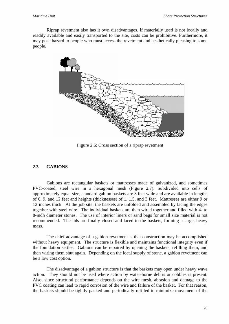
Riprap revetments are a very effective and popular method of controlling streambank erosion. A revetment is a facing of stone or other armoring material to protect a streambank or shoreline. A riprap revetment consists of layered, various-sized rocks placed on a sloping bank (Figure 2.6). The most commonly used material for riprap is broken limestone, dolomite or quartzite. The type of stone used usually determined by what is locally available. The variance in size and the rough angular surfaces of the rock allow the revetment to absorb the impact of the flowing water instead deflecting the flow which could cause erosion to an adjacent streambank area. The rough angular surfaces of the broken rocks also allows to fit together to form a dense layer of protection over the eroding bank.
Stones that appear to have smooth and rounded surface should be avoided if possible.
The surface of these stones does not allow the rocks to interlock which decreases resistance to movement. Broken asphalt should not be used because it has a low density and contains toxic chemicals which can leach out into the water.
Some of the advantages of riprap as an erosion treatment are that it is designed for high velocities and provides high degree of protection. Riprap is also relatively ease of installation and needs a minimal maintenance. In addition; riprap revetment system provides immediate long-term protection.
19
Maritime Unit Shore Protection Structures
Riprap revetment also has it own disadvantages. If materially used is not locally and readily available and easily transported to the site, costs can be prohibitive. Furthermore, it may pose hazard to people who must access the revetment and aesthetically pleasing to some people.
Figure 2.6: Cross section of a riprap revetment 2.3 GABIONS Gabions are rectangular baskets or mattresses made of galvanized, and sometimes PVC-coated, steel wire in a hexagonal mesh (Figure 2.7). Subdivided into cells of approximately equal size, standard gabion baskets are 3 feet wide and are available in lengths of 6, 9, and 12 feet and heights (thicknesses) of 1, 1.5, and 3 feet. Mattresses are either 9 or 12 inches thick. At the job site, the baskets are unfolded and assembled by lacing the edges together with steel wire. The individual baskets are then wired together and filled with 4- to 8-indh diameter stones. The use of interior liners or sand bags for small size material is not recommended. The lids are finally closed and laced to the baskets, forming a large, heavy mass.
The chief advantage of a gabion revetment is that construction may be accomplished without heavy equipment. The structure is flexible and maintains functional integrity even if the foundation settles. Gabions can be repaired by opening the baskets, refilling them, and then wiring them shut again. Depending on the local supply of stone, a gabion revetment can be a low cost option.
The disadvantage of a gabion structure is that the baskets may open under heavy wave action. They should not be used where action by water-borne debris or cobbles is present. Also, since structural performance depends on the wire mesh, abrasion and damage to the PVC coating can lead to rapid corrosion of the wire and failure of the basket. For that reason, the baskets should be tightly packed and periodically refilled to minimize movement of the
20

Maritime Unit Shore Protection Structures
stone and subsequent damage to the wire. Rusted and broken wire baskets also pose a safety hazard where traffic across them is required. Gabion structures require periodic inspections so that repairs are made before serious damage occurs.
Figure 2.7: Typical section of gabions 2.4 GROINS
Groins are constructed perpendicular to shore and extend out into the water. Used singly or in groups known as groin fields, they trap sand or retard its longshore movement along beaches. Sand accumulates in fillets on the updrift side of the groin, and the shoreline rotates to align itself with the crests of incoming waves. As the adjustment proceeds, the angle between the shoreline and the waves decreases and with it, the longshore transport rate. Sand fillets act as protective barriers, which waves can attack and erode without damaging the previously unprotected upland areas. A groin, without a sand fillet, cannot protect a shoreline from direct wave attack. A prime consideration with groin system design is evaluation of the net direction and amount of longshore sediment transport. Successful performance requires an adequate net longshore transport rate to form an updrift fillet. If the gross transport rate is high but nearly equally divided in both directions (small net transport), groins do not generally function well or successfully form large updrift fillets.
When first built, the sand trapped on a groin's updrift side is no longer available to replenish downdrift beaches, resulting in erosion. When a groin fills to capacity, material passes around or over it to the downdrift shore, but at a slower rate than before the groin was built. If downdrift erosion is unacceptable (it usually is), an alternative is to build more than one groin and fill the area between with sand (Figure 2.8 and 2.9). This will minimize downdrift damages and limit scour at the groin's shoreward end.
Groins are generally effective only when littoral materials are coarser than fine sand. Silts and clays tend to move in suspension and are not retained.
21

Maritime Unit Shore Protection Structures
Figure 2.9: Groins
Figure 2.9: Fill the area between groins with sand
Figure 2.10: Effects of Groins
22

Maritime Unit Shore Protection Structures
Important design considerations for groins include their height, length, and spacing (for a groin field). Height determines how much sand can pass over the structure; groins can be built either high or low with respect to the existing beach profile. Low groins, which essentially follow a foot or two above the natural beach profile, are widely used because they stabilize the beach but do not trap excessive amounts of sand and cause downdrift damages. High groins effectively block the supply of sand to downdrift beaches provided sand doesn't pass through them.
A groin's length must be sufficient to create the desired beach profile while allowing adequate passage of sand around its outer end. If a groin extends seaward past where waves break (breaker zone), sediment moving around the structure may be forced too far offshore to be returned to the downdrift beach. Therefore, the groin should not extend past the breaker zone, but it can be shorter provided that it traps a sufficient quantity of sand. All groins should be extended sufficiently landward to prevent their detachment from shore (flanking) if severe erosion occurs.
The correct spacing of groins depends on their length and the desired final shoreline shape. If groins are too far apart, excessive erosion can occur between them. If spaced too closely, they may not function properly, which is particularly critical for high, long groins where sand can only pass around the ends in a curved path back to the beach. If the groins are too close together, the sand is unable to reach the shore again before being forced seaward by the next downdrift groin. A common rule is to provide spacing equal to two or three times the groin length, measured from the water's edge.
Structurally, a groin must resist wave action, currents, the impact of floating debris, and earth pressures created by the difference in sand levels on the two sides. As other structures, a groin must also resist the scour created by waves breaking on the structure and by currents adjacent to it. 2.5 BEACH FILLS Beach fills are quantities of sand placed on the shoreline by mechanical means, such as dredging and pumping from offshore deposits, or overland hauling and dumping by trucks. The resulting beach provides some protection to the area behind it and also serves as a valuable recreational resource. The beach fill functions as an eroding buffer zone. As large waves strike it, sand is carried offshore and deposited in a bar. As the bar grows, it causes these large incoming waves to break farther offshore. The useful life of a fill, which depends on how quickly it erodes, can be completely eliminated in a short period of time by a rapid succession of severe storms. The owner must expect, therefore, to periodically add more fill as erosion continues. Beach fills generally have a relatively low initial cost but a regular maintenance cost of adding new fill (periodic renourishment). The rate at which new fill must be added depends on the relative coarseness of the fill material in relation to the native beach material. Ideally, fill and native beach materials should be perfectly matched, but this is virtually impossible. Generally speaking, if the fill
23
Maritime Unit Shore Protection Structures
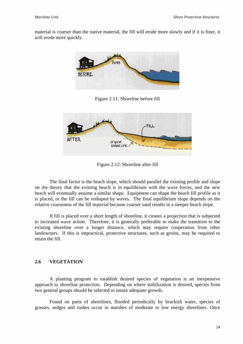
material is coarser than the native material, the fill will erode more slowly and if it is finer, it will erode more quickly.
Figure 2.11: Shoreline before fill
Figure 2.12: Shoreline after fill
The final factor is the beach slope, which should parallel the existing profile and slope on the theory that the existing beach is in equilibrium with the wave forces, and the new beach will eventually assume a similar shape. Equipment can shape the beach fill profile as it is placed, or the fill can be reshaped by waves. The final equilibrium slope depends on the relative coarseness of the fill material because coarser sand results in a steeper beach slope.
If fill is placed over a short length of shoreline, it creates a projection that is subjected to increased wave action. Therefore, it is generally preferable to make the transition to the existing shoreline over a longer distance, which may require cooperation from other landowners. If this is impractical, protective structures, such as groins, may be required to retain the fill. 2.6 VEGETATION
A planting program to establish desired species of vegetation is an inexpensive approach to shoreline protection. Depending on where stabilization is desired, species from two general groups should be selected to insure adequate growth.
Found on parts of shorelines, flooded periodically by brackish water, species of grasses, sedges and rushes occur in marshes of moderate to low energy shorelines. Once
24

Maritime Unit Shore Protection Structures
extensive and widely distributed, marsh areas were viewed in the past as useless and were subjected to filling and diking. However their destruction has lessened as their importance in the ecosystem and to shoreline protection has been realized.
Upland species (shrubs and trees but particularly grasses) are especially adapted to the low-nutrient, low-moisture environment of the higher beach elevations, where they are subject to abrasion by wind-blown sand particles. Used to trap sand and stabilize the beach, upland vegetation also improves the beauty of a shoreline, prevents erosion by intercepting raindrops, diminishes the velocity of overland flow, increases the soils infiltration rate, and provides a habitat for wildlife.
Even though vegetation provides significant help in stabilizing slopes and preventing erosion, vegetation alone cannot prevent erosion from heavy wave action, nor prevent movement of shoreline bluffs activated by groundwater action. In these instances, structural devices augmented with vegetation are recommended. The effectiveness of vegetation is also limited by characteristics of the site. For instance, the site requirements which determine the effectiveness of a tidal marsh planting include elevation and tidal regime, which determine the degree, duration, and timing of plant submergence; slope of the site; exposure to wave action; type of soil; salinity regime; and oxygen-aeration times. Plants which are specially adapted for higher beach elevations must tolerate rapid sand accumulation, flooding, salt spray, abrasion by wind-borne sand particles, wind and water erosion, wide temperature fluctuations, drought and low nutrient. Appropriate species also vary with geographical location, climate, and distance from the water (vegetative zone). 2.7 INFILTRATION AND DRAINAGE CONTROLS
Infiltration and drainage controls are often needed for stability along high bluff shorelines. Although many factors lead to slope stability problems, groundwater is one of the most important. The majority of slope failures and landslides occur during or after periods of heavy rainfall or increased groundwater elevations. Infiltration controls prevent water from entering the ground, while drainage controls remove water already present in the soil or on the surface.
Since water entering surface cracks can lead to further instability, these should be filled with compacted soil (preferably clay) as they develop. Surface runoff should also be diverted from critical areas of the bluff by either drainage ditches or swales.
The treatment of subsurface drainage problems is complex. Where such problems exist, a geotechnical engineer should be consulted. 2.8 SLOPE FLATTENING
25

Maritime Unit Shore Protection Structures
A bluff slope may be flattened to enhance its stability when adequate room exists at the top, and it does not interfere with the desired land use. Freshly excavated slopes should be planted to prevent erosion due to surface runoff. It may also be necessary to build a revetment or bulkhead at the toe of the slope to protect against wave action. 2.9 PERCHED BEACH
Perched beaches (Figure 2.13), which combine a low breakwater or sill and a fill, are beaches elevated (perched) above the normal level. They are suitable where offshore slopes are gradual enough to permit sill construction in reasonably shallow water at a distance from shore. The perched beach provides a broad buffer zone against wave action, while offering a potentially excellent recreational site.
Figure 2.13: Perched (elevated) beach
Perched beach sills can be built using most of the materials described for fixed breakwaters. They must be made sand-tight to retain the beach fill, however. Proper filtering should be provided beneath and behind the sill to prevent settlement and loss of the retained fill.
26

Maritime Unit Shore Protection Structures
This alternative provides broad buffer against wave action while offering a potentially
excellent recreational site. The sill can be constructed of various materials, but it must be impermeable to the passage of the retained beach sand by using, for instance, a filter cloth behind and beneath the structure. The cloth prevents the fill form escaping through any large voids in the sill and also stabilizes the structure against settlement. While a graded stone core could also be used in rock sill in place of filter cloth, the limited height of such sill generally precludes use of multi-layered structures of this kind. This figure also shows a splash apron which is provided to prevent scour and erosion of the beach fill from overtopping waves. 2.10 STRUCTURES AND FILLS
In addition to perched beaches, fills can also be incorporated in groin systems and with breakwaters. In fact, auxiliary fills are almost mandatory in most cases, because if such structures fill by natural accretion, serious erosion problems almost surely occur at downdrift. 2.11 STRUCTURES AND VEGETATIONS
While vegetation is one means of controlling shoreline erosion, its most serious deficiency is its restriction to areas of limited fetch because it cannot establish itself in heavy wave environments. By placing it in the shelter of a structure such as a breakwater, however, vegetation can be used in areas experiencing considerably heavier wave activity. The use of a temporary structure is particularly appealing because it protects the plants while they become established and it can be removed when the plant mature. 2.12 CEOTEXTILES IN COASTAL PROTECTION
Geotextiles are defined as permeable textiles used in conjunctions with soils or rocks, as integral part of a man-made project. The traditional method of controlling erosion is to shield the soil particles from the moving water with a flexible protective structure. There are many different forms of structure. There are many different forms of structure that can be utilized such as rip-rap (broken rocks) or heavy armour stones, concrete blocks, articulated concrete mattresses and gabion mattresses.
The weight of these protective structures also helps the soil particles in the bank to resist the effect of seepage into the waterway. However, the protective material is usually required to be permeable, in order to prevent the build up of hydrostatic pressure. The drainage openings, which can be very large in the case riprap, would expose the underlying soil to erosion, if other protective measures were not taken. A graded aggregate filter is therefore traditionally used between the natural soil and the protective material could make use of as many as five layers of differently graded aggregates necessary in such a granular
27

Maritime Unit Shore Protection Structures
filter. It can prove difficult and expensive to install a multi layer erosion protection and filtration system, especially if this has to be placed under moving water. 2.12.1 Geotextile filters
The use of geotextile filter can simplify construction of the erosion control
measures, as illustrated in Figure 2.14, where it is replaces several layers of granular filter beneath riprap armour. A geotextile filter can also be used in a similar manner, beneath gabion mattresses or articulated concrete mattresses. The geotextile is placed in contact with and down the gradient of soil to be drained. Water and any particles suspended in the water which are smaller than a given size flow through the geotextile. Those soil particles larger than the size are stopped and prevented from being carried away. The geotextile should be sized to prevent soil particle movement. The geotextile substitute for and serve the same function as the traditional granular filter
Figure 2.14: Geotextile filter replacing a multi-layer granular filter in bank protection scheme 2.12.2 Riprap Protection Figure 2.15 shows the most widely used system of protection, which is bonded riprap laid over a layer of thick composite geotextile. This is intended for use on the banks of waterways which have a side slope of between 1 in 4 and 1 in 3. The geotextile filter is laid on the prepared soil surface and is covered by the bonded riprap, without the use of any intermediate blanket layer Bonded riprap is less susceptible to wave induced movement than loose riprap, and smaller sized stones may therefore be utilized. This usually gives bonded riprap an economic
28

Maritime Unit Shore Protection Structures
advantage over loose riprap. Small quantities of either cement or hot bitumen are used as the bonding compound and are mixed with riprap stones before placing. When cement is used, care must be taken not to use too high a water content or too large a quantity of cement as this could smear the surface of the geotextile.
Figure 2.15: The bonded riprap protection systems for canal sides
In some soils, there is a tendency for the particle to become loosened in the wave zone, even when protected by the geotextile and the riprap. Without precautions, the loosened soil particles may move down the slope, to produce a bulge and a depression in the protection works, as shown in Figure 2.16. This problem can be avoided by using a composite geotextile in which a thick rough geotextile is bonded to a thinner geotextile filter layer.
Figure 2.16: Bulging due to soil migration beneath the geotextile
The weakest part in bank protection design is probably the toe of the revetment. If this is subjected to scour it will undermined and will initially bridge over the scour zone, due to the bonding material in the riprap. Without contact between riprap and the soil, the erosion rate increases until riprap collapses into the void. The toe of riprap is then so damaged that pieces break away in clumps. When the erosion protection is installed in dry conditions, the
29

Maritime Unit Shore Protection Structures
simplest form enhanced toe protection is to extend the riprap revetment into the bed of waterway to a depth exceeding the anticipated scour, as shown in Figure 2.17. An alternative method is to fold over and sew the end of the geotextile sheet (Figure 2.18), to produce a cylinder about 0.4m high and 0.6m wide, which is filled with clay. The riprap on the canal bed is left unbounded, ensuring that this section is fully flexible and is able to deform with the onset of scour, thereby maintaining the protection and limiting the rate of damage.
Figure 2.17: Extended toe to deal with scour
Figure 2.18: Clay filled geotextile toe used to control erosion 2.12.3 Concrete Block Protection Although it is possible to use loose, closely fitting, concrete blocks for bank protection, these do not have any significant advantages over riprap protection systems.
30

Maritime Unit Shore Protection Structures
However, if some means of linking the concrete blocks together is utilized, than this additional integrity enables a lighter weight of riprap protection. These flexibly jointed block systems are collectively known as articulated block revetments. The two most common forms of linking the concrete blocks together are; cables thread through the blocks (Figure 2.19) and individual connections to a continuous geotextile sheet (Figure 2.20).
Figure 2.19: An element of an articulated block revetment system
Figure 2.20: Prefabricated sheet of concrete blocks bonded to a geotextile 2.14.4 Gabion Mattress Protection
31

Maritime Unit Shore Protection Structures
The most common form of gabion used in bank protection is a rectangular gabion mattress. The outer mesh of gabion is usually formed from geotextile nets or steel mesh protected by zinc or PVC coating. 2.13 SELECTION AMONG AVAILABLE OPTIONS 2.13.1 Shoreform Compatibility
Certain approaches are better suited to particular shoreline configurations than others. It is important to choose a method appropriate to the dominant shoreform at the site. 2.13.1.1Bluff Shorelines
The no action alternative can be appropriate since it does not disrupt the natural shoreline processes and requires no investment for protective structures. The property, however, may eventually be totally destroyed by erosion. While relocation also does not disrupt shoreline processes and permanently eliminates any threat to buildings if done properly, it also requires special equipment and skills and can cost as much as or more than a protective structure.
Bulkheads are ideally suited either for full-height retention of low bluffs or as toe protection for high bluffs. They can be constructed of readily available materials, are easily repaired if damaged, and are particularly useful with steep offshore slopes. They can, however, induce toe scour and loss of remaining beach material from the force of reflected waves. They also have high initial costs and some require special pile driving equipment which may have difficulty reaching the work site. Revetments are sometimes effective in bluff situations. Low bluffs that can be re-graded to a stable slope may be effectively protected by revetments.
Revetments can protect the toes of high bluffs, either alone or in conjunction with another device. Breakwaters reduce wave energy reaching the bluff but do not provide positive protection to the toe. They may build or maintain a sand beach, which provides some protection against normal waves but would be ineffective against storm waves. They require an adequate sand supply and gentle offshore slopes. Groins provide only a buffer by building or holding a beach. Since they require a natural sand supply, they would not work in a clay or silt bluff area unless sand were imported. Beach fills only dissipate normal wave action and would not be effective during severe storms. Vegetation provides little protection until well established and, even then, does not positively protect against large storm waves.
Drainage controls are mandatory if groundwater and infiltration adversely affect slope stability. They provide no toe protection against wave action and can be expensive. Also, they are difficult to properly design, and may require the efforts of a qualified professional engineer. Slope flattening provides a permanent solution for slope stability problems but does
32

Maritime Unit Shore Protection Structures
not provide protection against continued wave action. It also requires adequate setback room at the top of the bluff for the slope. Perched beaches would protect the bluff from normal wave action but would not provide positive toe protection during storms. A combination approach can be the best solution. For instance, drainage controls should be used as needed, possibly with slope flattening as well. Toe protection could be provided with a revetment along with a fronting sand beach for additional protection (provided offshore slopes are mild). Vegetation planted on the re-graded slope would prevent erosion from runoff and also help to stabilize a beach fill. 2.13.1.2Sand Beaches or Low Plains
The no action and relocation alternatives are applicable. Bulkheads are generally inappropriate unless an elevated feature is needed, such as a promenade or parking lot. Vertical bulkheads induce toe scour and wave reflections, and could cause a total loss of beach. Revetments are suited for protecting features directly behind the beach since they absorb wave energy and are flexible if settlement occurs. However, they have an adverse aesthetic effect on the beach and can limit use or access to the shore. Their use by a single landowner is generally a problem because they are subject to flanking. Breakwaters are also well suited because they trap and hold sand moving both alongshore and on or offshore. However, they can cause extensive downdrift erosion damages and they are expensive to build. Groins can effectively build beaches on their updrift sides but can also cause accelerated downdrift erosion. Their functional behavior is complex and difficult to predict. Beach fill retain the natural form and character of the beach and enhance its recreational potential. Local sources of suitable sand are not always available, however, and fills require periodic renourishment. Vegetation, effective in low wave energy situations, has low initial costs and enhances natural appearance. Unfortunately, foot and vehicular traffic damage plantings. Drainage controls and slope flattening are not applicable to beach shorelines. Perched breaches are ideally suited as they increase the available beach area. Combination methods are often excellent, such as a perched beach that is further stabilized with vegetation. 2.13.2 Effects on Coastal Processes and Adjacent Properties Table 2.1 lists the effects of various options on shoreline processes.
Table 2.1: The effects of various options on shoreline processes
Option Effect
33

Maritime Unit Shore Protection Structures
No Action
Eroding shoreline will continue to supply material for transport to adjacent shores.
Relocation Eroding shoreline will continue to supply material for transport to adjacent shores.
Bulkheads Protect eroding shorelines that may have been supplying material to downdrift areas, which may then experience accelerated erosion. The fronting beach may experience increased erosion due to wave reflections.
Revetments Protect eroding shorelines that may have been supplying material to downdrift areas, which may then experience accelerated erosion.
Breakwaters Diminished wave energy behind such structures induces deposition. If the amount of sediment accumulation is significant, the downdrift shore may experience accelerated erosion. If wave energy is significantly reduced, the area behind the breakwater may not have sufficient circulation to maintain water quality.
Groins Impede longshore transport and induce sedimentation. The downdrift shoreline may experience accelerated erosion due to lack of material supply.
Beach Fills Provide a new supply of material to the littoral transport system. Increased suspended sediment loads could shoal adjacent navigation channels.
Vegetation If some material is retained that previously was transported alongshore, it is possible that the downdrift shoreline may experience minimal erosion damages.
Drainage Controls No significant effects.
Slope Flattening
No significant effects.
Perched Beaches
See "Beach Fills".
Structures and Fills
By filling the structures to near capacity with sand, the longshore transport may pass around the structure and continue to supply the downdrift shore.
Structures and Vegetation
The vegetation help the structure more effectively retain sand, which could cause increased downdrift erosion.
2.13.3 Effects on Shoreline Uses
Table 2.2 lists the significant effects of the various options on shoreline uses.
Table 2.2: Significant effects of the various options on shoreline uses Option Advantages Disadvantages
34

Maritime Unit Shore Protection Structures
No Action Relocation Bulkheads Revetments Groins Beach Fills Vegetation Drainage Control Slope Flattening Perched Beaches Structures and Fills Structures and Vegetation
• No consistent positive or negative effects on shoreline uses.
• No consistent or negative effects on
shoreline uses. • When used for wharves, provide
direct boat access to the shore. • Unless placed high on a beach, they
may binder swimming, jogging, walking or fishing.
• Unless fronted by a sufficient beach
width, they may binder swimming, jogging, walking or fishing.
• Rubble structures may provide a
habitat for aquatic life. • Can provide access to deeper water
for fishing • Trapped sand fillets increase the
available • beach area • Do not obstruct access to and from
the beach • Provide more beach area for
swimming, jogging, walking and fishing
• Do not restrict access to and from or along the beach.
• Provide a habitat for aquatic life • Creates an opportunity for nature
study • When a fronting beach already
exists, the potential for swimming, boating, jogging, etc., is unaffected.
• When a fronting beach already
exists, the potential for swimming, boating, jogging, etc., is unaffected.
• Access to the beach is enhanced. • Provide more beach to be used for
swimming, jogging, walking, and fishing.
• Do not restrict access to and from or along the beach.
• Provide more beach area for
swimming, jogging, walking and fishing
• Marsh plants provide a habitat for
aquatic life.
• Can limit access to beach so that stairs may be
required • Tend to cause erosion of existing fronting beach and
possibly adjacent shores. • Certain designs (e.g., gabions or quarrystone) limit
access to the beach so that stairs may be needed. • If the fronting beach is normally submerged at hight
tide, partially submerged revetments may pose a hazard to swimmers.
• May limit travel along the beach • Low groins, when submerged, can be a hazard to
boats if not appropriately marked • Rip currents may be induced along groins which
may be hazardous to bathers. • Increased turbidity during placement may cause
temporary impairment of fishing.
• Restricts beach use because plantings cannot be
subjected to traffic. • No impairment of shoreline uses.
• Reduce the land available at the top of the slope.
• The sudden drop off the end of the beach at the sill
can pose a hazard to bathers. • If not properly marked when submerged, the sill
can be a hazard to boaters. • Increased turbidity during fill placement may cause
temporary impairment of fishing. • Plantings may restrict beach use because they
cannot be subjected to traffic.
2.13.4 Effects on the Environment The environmental effects of low cost devices, because of their limited extent, will generally be minimal. Such impacts as may occur are summarized in Table 2.3.
35
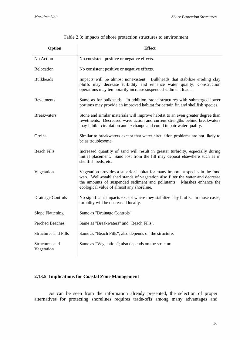
Maritime Unit Shore Protection Structures
Table 2.3: impacts of shore protection structures to environment
Option
Effect
No Action
No consistent positive or negative effects.
Relocation No consistent positive or negative effects.
Bulkheads Impacts will be almost nonexistent. Bulkheads that stabilize eroding clay bluffs may decrease turbidity and enhance water quality. Construction operations may temporarily increase suspended sediment loads.
Revetments Same as for bulkheads. In addition, stone structures with submerged lower portions may provide an improved habitat for certain fin and shellfish species.
Breakwaters Stone and similar materials will improve habitat to an even greater degree than revetments. Decreased wave action and current strengths behind breakwaters may inhibit circulation and exchange and could impair water quality.
Groins Similar to breakwaters except that water circulation problems are not likely to be as troublesome.
Beach Fills Increased quantity of sand will result in greater turbidity, especially during initial placement. Sand lost from the fill may deposit elsewhere such as in shellfish beds, etc.
Vegetation Vegetation provides a superior habitat for many important species in the food web. Well-established stands of vegetation also filter the water and decrease the amounts of suspended sediment and pollutants. Marshes enhance the ecological value of almost any shoreline.
Drainage Controls No significant impacts except where they stabilize clay bluffs. In those cases, turbidity will be decreased locally.
Slope Flattening
Same as "Drainage Controls".
Perched Beaches
Same as "Breakwaters" and "Beach Fills".
Structures and Fills
Same as "Beach Fills"; also depends on the structure.
Structures and Vegetation
Same as “Vegetation”; also depends on the structure.
2.13.5 Implications for Coastal Zone Management
As can be seen from the information already presented, the selection of proper alternatives for protecting shorelines requires trade-offs among many advantages and
36

Maritime Unit Shore Protection Structures
disadvantages. No single alternative will apply in every case and each has to be considered on its own merits.
Consistency in the planning or cost shore protection systems requires an encompassing set of guidelines or goals that should be established by each local jurisdiction. The desire is to satisfy a community's development plans without risking property or life, while simultaneously protecting its ecological resources. Each community has its own set of attitudes, social goals, and political styles which will determine the policies it develops.
The purpose of proper shoreline management is to look beyond each individual site to the whole community. Uncontrolled development may adversely affect the shoreline in a number of ways. Management policies should, therefore, be concerned with minimizing changes in patterns of drainage and runoff, preserving ecologically valuable areas such as dunes and wetlands, preserving natural protective forms such as dunes and beaches, avoiding adverse alternation of coastal configurations, protecting coastal waters from pollution, and restoring damaged areas to former conditions. These policies would be applied to the earlier identified shoreforms in relation to low cost shore protection as follows. 2.13.5.1Bluff Shorelines
Adverse uses of lands adjacent to the tops of banks or bluffs should be avoided. Clearing of trees and undergrowth, constructing buildings, or plowing could all destabilize existing slopes by increasing seepage and surface erosion or by adding extra weight (surcharge) which the bluff must supported. Surcharges, in particular, should be avoided. Changes in surface drainage patterns should be planned to divert the flow away from the bluff face.
Zoning regulations should be instituted to restrict development to areas landward of setback lines. These should be established based on projected shoreline recession amounts over a specified future time period. In fact, in localities threatened with erosion, these setback lines are required for endangered structures to qualify for insurance under the National Flood Insurance Program.
Activities should be discouraged that will alter or disturb the bluff face or toe. Stable bluffs should not be stripped of vegetation, nor should they be unnecessarily excavated, as this could lead to slides and slope failures. This does not eliminate slope flattening or drainage controls as alternatives, because these are used when the bluffs are inherently unstable and must be treated to restore stability. Plantings and other uses of vegetation should be encouraged on all excavated or natural slopes to increase stability and reduce erosion. Toe protection should be provided in all cases where wave attack undermines the bluff. Any appropriate device outlined within this report, subject to other engineering, shoreline use, or environmental criteria, would be acceptable. 2.13.5.2Beach Shorelines
37
Maritime Unit Shore Protection Structures
Activities should be discouraged that remove sand from the active beach zone, whether for fill at other areas, or for placement elsewhere on the beach profile. This would include dredging for beach fills, as a source of concrete aggregates, or as fill for bag structures.
New development should be located inland from the active beach to preclude the need for future shore protection. Setback lines should be established and observed. In most states, public domain is maintained as the area up to the mean high water line (MHHW on the west coast). In some states (e.g. Texas) public domain extends higher, to the point of permanent vegetation. In addition, local Governments in some areas have zoned additional setbacks of 30 feet or more from the MHW line, with the area designated for community recreational purposes.
Actions that adversely affect the littoral system should be discouraged. Accretion devices such as breakwaters and groins interfere with sand transport and may cause downdrift erosion. Sand permanently trapped behind such structures is also unavailable during transport reversals and could cause updrift erosion damages. Supplemental fill (preferably from inland sources) should be placed in the shadow zone of all such structures to minimize adjacent property damages.
Restoration of eroded beaches should be encouraged as part of any shore protection plan. Vegetation may be useful in some locations to further assist stability.
Excavation and removal of dunes should be discouraged because dunes serve as the natural front line of defense for the shore. Control should be exercised through local zoning ordinances or building codes that require special permits for excavation in dune areas. All new development should be located landward of dunes.
Existing vegetation, particularly on dunes, should be protected, primarily by restricting pedestrian or vehicular traffic. Special roads or walkways may be required in some cases.
Dunes should be restored and stabilized whenever possible as part of a comprehensive shore protection plan. Vegetation and snow fencing are principal means of accomplishing this. 2.13.5.3 Wetlands and Marshes
Alterations to the surface of marshes by excavating, filling, clearing, paving or grading should generally be prohibited. The value of marshes for shore protection and as ecological resources has been stressed. In cases of essential development, marsh areas that are destroyed may be replaced by newly developed marshes elsewhere as compensation and
38

Maritime Unit Shore Protection Structures
as a requirement for development. As an alternative, adjacent damaged marshes may be restored to their full function to replace those taken by development.
Diking or draining of marshes is generally harmful and should not be permitted. Permanent structures that would impair marsh functions should be discouraged. Placement of buildings on piles is often an acceptable alternative, as are elevated walkways, shelters, footbridges, and boat houses.
Discharge of pollutants should be restrained. Marshes serve a valuable water purification function but their ability to absorb pollutants is finite and limited.
Marshes should be restored to full function as part of any comprehensive shore protection plan. 2.14 GLOSSARY
Accretion - Accumulation of sand or other beach material at a point due to natural action of waves, currents and wind. A build-up of the beach. Alongshore - Parallel to and near the shoreline; same as LONGSHORE. Backhoe - Excavator similar to a power shovel except that the bucket faces the operator and is pulled toward him. Bar - Fully or partly submerged mound of sand, gravel, or other unconsolidated material built on the bottom in shallow water by waves and currents. Beach - Zone of sand or gravel extending from the low water line to a point landward where either the topography abruptly changes or permanent vegetation first appears. Beach Fill - Sand or gravel placed on a beach by mechanical methods. Beach, Perched - See PERCHED BEACH. Bluff - High, steep bank at the water’s edge. In common usage, a bank composed primarily of soil. See CLIFF. Boulders - Large stones with diameters over 10 inches. Larger than COBBLES. Breaker - A wave as it spills, plunges or collapses on a shore, natural obstruction, or man-made structure. Breaker Zone - Area offshore where waves break. Breaking Depth - Stillwater depth where waves break. Breakwater - Structure aligned parallel to shore, sometimes shore connected, that provides protection from waves.
39

Maritime Unit Shore Protection Structures
Bulkhead - A structure that retains or prevents sliding of land or protects the land from wave damage. Clay - Extremely fine-grained soil with individual particles less than 0.00015 inches in diameter. Cliff - High steep bank at the water's edge. In common usage, a bank composed primarily of rock. See BLUFF. Cobbles - Rounded stones with diameters ranging from 3 to 10 inches. Cobbles are intermediate between GRAVEL and BOULDERS. Crest - Upper edge or limit of a shore protection structure. Cross Section - View of a structure or beach as if it were sliced by a vertical plane. The cross section should display structure, ground surface, and underlying material. Culm - Single stem of grass. Current - Flow of water in a given direction. Current, Longshore - Current in the breaker zone moving essentially parallel to shore and usually caused by waves breaking at an angle to shore. Also called alongshore current. Deep Water - Area where surf ace waves are not influenced by the bottom. Generally, a point where the depth is greater than one-half the surface wavelength. Diffraction- Progressive reduction in wave height when a wave spreads into the shadow zone behind a barrier after the wave has passed its end. Diurnal - Period or cycle lasting approximately one day. A diurnal tide has one high and one low in each cycle. Downdrift - Direction of alongshore movement of littoral materials. Dune - Hill, bank, bluff, ridge, or mound of loose, wind-blown material, usually sand. Duration - Length of time the wind blows in nearly the same direction across a FETCH (generating area). Ebb Tide - Part of the tidal cycle between high water and the next low. The falling tide. Equilibrium - State of balance or equality of opposing forces. Erosion - Wearing away of land by action of natural forces. Fetch - Area where waves are generated by wind, which has steady direction and speed. Sometimes called FETCH LENGTH.
40

Maritime Unit Shore Protection Structures
Fetch Length - Horizontal direction (in the wind direction) over which a wind generates waves. In sheltered waters, often the maximum distance that wind can blow across water. Filter Cloth - Synthetic textile with openings for water to escape, but which prevents passage of soil particles. Flood Tide - Part of the tidal cycle between low water and the next high. The rising tide. Glacial Till - Unstratified glacial drift consisting of unsorted clay, sand, gravel, and boulders, intermingled. Longshore - Parallel to and near the shoreline: same as ALONGSHORE. Longshore Transport Rate - Rate of transport of littoral material parallel to shore. Usually expressed in cubic yards per year. Low Tide - Minimum elevation reached by each falling tide. Low Water Datum (LWD) - The elevation of each of the Great Lakes to which are referenced the depths shown on navigation charts and the authorized depths of navigation projects. Marsh - Area of soft, wet, or periodically inundated land, generally treeless, and usually characterized by grasses and other low growth. Mean Higher High Water (MHHW) - Average height of the daily higher high waters over a 19-year period. Only the higher high water of each pair of high waters of a tidal day is included in the mean. Mean High Water (MHW) - Average height of the daily high waters over a 19-year period. For semidiurnal or mixed tides, the two high waters of each tidal day are included in the mean. For diurnal tides, the single daily high water is used to compute the mean. Mean Lower Low Water (MLLW) - Average height of the daily lower-low waters of a 19-year period. Only the lower low water of each pair of low waters of a tidal day is included in the mean. Long used as the datum for Pacific coast navigation charts, it is now gradually being adopted for use across the United States. Mean Low Water (MLW) - Average height of the low waters over a 19-year period. For semidiurnal and mixed tides, the two low waters of each tidal day are included in the mean. For a diurnal tide, the one low water of each tidal day is used in the mean. Mean Low Water has been used as datum for many navigation charts published by the National Ocean Survey, but it is being phased out in favor of Mean Lower Low Water for all areas of the United States. Mean Sea Level - Average height of the sea surface over a 19-year period. Not necessarily equal to MEAN TIDE LEVEL.
41

Maritime Unit Shore Protection Structures
Mean Tide Level - Plane midway between MEAN HIGH WATER and MEAN LOW WATER. Not necessarily equal to MEAN SEA LEVEL. Also called half-tide level. Mixed Tide - A tide in which there is a distinct difference in height between successive high and successive low waters. For mixed tides there are generally two high and two low waters each tidal day. Mixed tides may be described as intermediate between semidiurnal and diurnal tides. Module - A structural component, a number of which are joined to make a whole. Neap Tides - Tides with decreased ranges that occur when the moon is at first or last-quarter- ;4nl in opposition to each other. The neap range is smaller than the mean range for semidiurnal and mixed tides. Nearshore - In beach terminology, an indefinite zone extending seaward from the shoreline well beyond the breaker zone Nourishment - Process of replenishing a beach either naturally by longshore transport or artificially by delivery of materials dredged or excavated elsewhere. Offshore - (1) (Noun) In beach terminology, comparatively flat zone of variable width extending from the breaker zone to the seaward edge of the Continental Shelf. (2) (Adjective) Direction seaward from the shore. Overtopping - Passing of water over a structure from wave runup or surge action. Peat - Residual product produced by partial decomposition of organic matter in marshes and bogs. Peat Pot (vegetation) - Pot formed from compressed peat and filled either with soil or peat moss in which a plant or plants, grown from seed, are transplanted without being removed from the pot. Perched Beach - Beach or fillet of sand retained above the otherwise normal profile level by a submerged dike or sill. Permeable - Having openings large enough to permit free passage of appreciable quantities of (1) sand or (2) water. Pile - Long, heavy section of timber, concrete or metal driven or jetted into the earth or seabed as support or protection. Pile, Sheet - Pile with a generally slender, flat cross section driven into the ground or seabed and meshed or interlocked with like members to form a diaphragm, wall, or bulkhead. Piling - Group of piles.
42
Maritime Unit Shore Protection Structures
Plug - Core containing both plants and underlying soil, usually cut with a cylindrical coring device and transplanted to a hole cut by the same device. Polyvinyl Chloride (PVC) - Plastic material (usually black) that forms a resilient coating suitable for protecting metal from corrosion. Profile, Beach - Intersection of the ground surface with a vertical plane that may extend from the top of the dune line to the seaward limit of sand movement. PVC - See POLYVINYL CHLORIDE. Ravelling - Progressive deterioration of a revetment under wave action. Refraction (of water waves) - (1) Process by which direction of a wave moving in shallow water at an angle to the contours is changed. Part of the wave advancing in shallower water moves more slowly than the part still advancing in deeper water, causing the wave crest to bend toward alignment with the underwater contours. (2) Bending of wave crests by currents. Revetment - Facing of stone, concrete, etc., built to protect a scarp, embankment, or shore structure against erosion by waves or currents. Rhizome - Underground stem or root stock. New shoots are usually produced from the tip of the rhizome. Riprap - Layer, facing, or protective mound of stones randomly placed to prevent erosion, scour, or sloughing of a structure or embankment; also, the stone so used. Rubble - (1) Loose, angular, waterworn stones along a beach. (2) Rough, irregular fragments of broken rock or concrete. Runup - The rush of water up a structure or beach on breaking of a wave. Amount of runup is the vertical height above stillwater level that the rush of water reaches. Sand - Generally, coarse-grained soils having particle diameters between 0.18 and approximately 0.003 inches. Sands are intermediate between SILT and GRAVEL. Sandbag - Cloth bag filled with sand or grout and used as a module in a shore protection device. Sand Fillet- Accretion trapped by a groin or other protrusion in the littoral zone. Scour - Removal of underwater material by waves or currents, especially at the base or toe of a shore structure. Screw Anchor - Type of metal anchor screwed into the bottom for holding power. Seawall - Structure separating land and water areas primarily to prevent erosion and other damage by wave action. See also BULKHEAD.
43
Maritime Unit Shore Protection Structures
Semidiurnal Tide - Tide with two high and two low waters in a tidal day, each high and each low approximately equal in stage. Setup, Wind - Vertical rise in the Stillwater level on a body of water caused by piling up of water on the shore due to wind action. Synonymous with wind tide and STORM SURGE. STORM SURGE usually pertains to the ocean and large bodies of water. Wind setup usually pertains to reservoirs and smaller bodies of water. Shallow Water - Commonly, water of such a depth that surface waves are noticeably affected by bottom topography. It is customary to consider water of depths less than one-twentieth the surface wavelength as shallow water. Sheet Pile - see PILE, SHEET. Shoot - Collective term applied to the STEM and leaves, or any growing branch or twig. Shore - Narrow strip of land in immediate contact with the sea, inc uding the zone between high and low water lines. A shore of unconsolidated material is usually called a beach. Shoreline - intersection of a specified plane of water with the shore or beach (e.g., the high water shoreline would be the intersection of the plane of mean high water with the shore or beach). Line delineating the shoreline on National Ocean Survey nautical charts and surveys approximates the mean high water line. Sill - Low offshore barrier structure whose crest is usually submerged, designed to retain sand on its landward side. Silt - Generally refers to fine-grained soils having particle diameters between 0.003 and 0.00015 inches. Intermediate between CLAY and SAND. Slope - Degree of inclination to the horizontal. Usually expressed as a ratio, such as 1:25 or 1 on 25, indicating 1-unit vertical rise in 25 units of horizontal distance; or in degrees from horizontal. Specifications - Detailed description of particulars, such as size of stone , quality of materials, contractor performance, terms, and quality control. Sprig - Single plant with its roots relatively bare, as pulled apart from a clump and used for transplanting. Stem - Main axis of a plant, leaf-bearing and flower-bearing, as distinguished from the root-bearing axis. Stillwater Level - Elevation that the surface of the water would assume if all wave action were absent. Storm Surge - Rise above normal water level on the open coast due to action of wind on the water surface. Storm surge resulting from a hurricane also includes the rise in
44

Maritime Unit Shore Protection Structures
level due to atmospheric pressure reduction as well as that due to wind stress. See SETUP, WIND. Swell - Wind-generated waves traveling out of their generating area. Swell characteristically exhibits a more regular and longer period, and has flatter crests than waves within their fetch. Tidal Range - Difference in height between consecutive high and low or higher high and lower low) waters. The mean range is the difference in height between mean high water and mean low water. The diurnal range is the difference in height between mean higher high water and mean lower low water. For diurnal tides, the mean and diurnal ranges are identical. For semidiurnal and mixed tides, the spring range is the difference in height between the high and low waters during the time of spring tides. Tide - Periodic rising and falling of water resulting from gravitational attraction of the moon, sun and other astronomical bodies acting upon the rotating earth. Although the accompanying horizontal movement of the water resulting from the same cause is also sometimes called tide, it is preferable to designate the latter as tidal current, reserving the name TIDE for vertical movement. Tide Station - Place at which tide observations are being taken. A primary tide station is a location where continuous observations are taken over a number of years to obtain basic tidal data for the locality. A secondary tide station is operated over a short period of time to obtain data for a specific purpose. Tie Rod - Steel rod used to tie back the top of a bulkhead or seawall. Also, a U-shaped rod used to tie Sandgrabber blocks together, or a straight rod used to tie Nami Rings together. Tiller - A plant SHOOT which springs from the root or bottom of the original plant stalk. Topography - Configuration of a surface, including relief, position of streams, roads, buildings, etc. Transplant - SHOOT or CULM removed from one location and replanted in another. Trough of Wave - Lowest part of a waveform between successive crests. Also, that part of a wave below Stillwater level. Updrift - Direction opposite the predominant movement of littoral materials in longshore transport. Wake (boat) - Waves generated by the motion of a vessel through water. Wale - Horizontal beam on a bulkhead used to laterally transfer loads against the structure and hold it in a straight alignment. Waterline - Juncture of land and sea. This line migrates, changing with the tide or other fluctuation in water level. Where waves are present on the beach, this line is
45
Maritime Unit Shore Protection Structures
also known as the limit of backrush. (Approximately, the intersection of land with Stillwater level.) Wave - Ridge, deformation, or undulation of the surface of a liquid. Wave Climate - Normal seasonal wave regimen along a shoreline. Wave Crest - Highest part of a wave or that part above Stillwater level. Wave Diffraction - See DIFFRACTION. Wave Direction - Direction from which a wave approaches. Wave Height - Vertical distance between a crest and the preceding trough. Wavelength - Horizontal distance between similar points on two successive waves measured perpendicular to the crest. Wave Period - Time in which a wave crest traverses a distance equal to one wavelength. Time for two successive wave crests to pass a fixed point. Wave Refraction - See REFRACTION (of water waves). Wave Steepness - Ratio of wave height to wavelength. Wave Trough - Lowest part of a wave form between successive crests. Also, that part of a wave below that part of a wave below Stillwater level. Weep Hole - Hole through a solid revetment, bulkhead, or seawall for relieving pore pressure. Wind Setup - See SETUP, WIND. Windward - Direction from which wind is blowing. Wind Waves - (1) Waves being formed and built up by wind. (2) Loosely, any waves generated by wind.
2.15 REFERENCES
1. The Conservation Foundation, "Coastal Environmental Management: Guidelines for Conservation of Resources and Protection Against Storm Hazards," Washington, D. C., 1980.
2. U.S. Army Corps of Engineers, "Shore Protection Manual", Coastal Engineering
Research Center, Ft. Beivoir, Virginia, 1977a.
3. U.S. Army Corps of Engineers, "Regulatory Program of the Corps of Engineers," Federal Register, Vol. 42, No. 138, Washington, D. C., 19 July 1977b.
46
Maritime Unit Shore Protection Structures
4. U. S. Army Corps of Engineers, "Pickering Beach, Delaware: Preconstruction Report", Engineer District, Philadelphia, January 1978.
5. U.S. Army Corps of Engineers, "Erosion Control With Smooth Cordgrass, Gulf
Cordgrass, and Saltmeadow Cordgrass on the Atlantic Coast," Coastal Engineering Research Center, TN-V-2, Washington D.C., March 1980.
6. U.S. Army Corps of Engineers, "Low Cost Shore Protection: Final Report on the
Shoreline Erosion Control Demonstration Program", Office, Chief of Engineers, U. S. Army Corps of Engineers, Washington, D. C., 1981.
7. Winterkorn, H. F., and Fang, H. Y., Foundation Engineering Handbook, Van
Nostrand Reinhold Company, New York, 1975.
47

Maritime Unit Shore Protection Structures
APPENDIX
48

EM 1110-2-161430 June 1995
US Army Corpsof Engineers
ENGINEERING AND DESIGN
Design of Coastal Revetments,Seawalls, and Bulkheads
ENGINEER MANUAL
DEPARTMENT OF THE ARMY EM 1110-2-1614U.S. Army Corps of Engineers
CECW-EH-D Washington, DC 20314-1000
ManualNo. 1110-2-1614 30 June 1995
Engineering and DesignDESIGN OF COASTAL REVETMENTS, SEAWALLS, AND BULKHEADS
1. Purpose. This manual provides guidance for the design of coastal revetment, seawalls, andbulkheads.
2. Applicability. This manual applies to HQUSACE elements, major subordinate commands (MSC),districts, laboratories, and field operating activities (FOA) having civil works responsibilities.
3. Discussion. In areas subject to wind-driven waves and surge, structures such as revetments,seawalls, and bulkheads are commonly employed either to combat erosion or to maintain developmentat an advanced position from the natural shoreline. Proper performance of such structures is pre-dicated on close adherence to established design guidance. This manual presents important designconsiderations and describes commonly available materials and structural components. All applicabledesign guidance must be applied to avoid poor performance or failure. Study of all available structuralmaterials can lead, under some conditions, to innovative designs at significant cost savings for civilworks projects.
FOR THE COMMANDER:
This manual supersedes EM 1110-2-1614, dated 30 April 1985.

DEPARTMENT OF THE ARMY EM 1110-2-1614U.S. Army Corps of Engineers
CECW-EH-D Washington, DC 20314-1000
ManualNo. 1110-2-1614 30 June 1995
Engineering and DesignDESIGN OF COASTAL REVETMENTS, SEAWALLS, AND BULKHEADS
Table of Contents
Subject Paragraph Page Subject Paragraph Page
Chapter 1IntroductionPurpose . . . . . . . . . . . . . . . . . . . . . 1-1 1-1Applicability . . . . . . . . . . . . . . . . . . 1-2 1-1References . . . . . . . . . . . . . . . . . . . 1-3 1-1Background. . . . . . . . . . . . . . . . . . . 1-4 1-1Discussion . . . . . . . . . . . . . . . . . . . 1-5 1-1
Chapter 2Functional DesignShoreline Use. . . . . . . . . . . . . . . . . 2-1 2-1Shoreline Form and
Composition . . . . . . . . . . . . . . . . . 2-2 2-1Seasonal Variations
of Shoreline Profiles . . . . . . . . . . . 2-3 2-1Design Conditions
for Protective Measures. . . . . . . . . 2-4 2-1Design Water Levels. . . . . . . . . . . . 2-5 2-1Design Wave Estimation. . . . . . . . . . 2-6 2-2Wave Height and Period Variability
and Significant Waves. . . . . . . . . . 2-7 2-2Wave Gauges and
Visual Observations. . . . . . . . . . . . 2-8 2-3Wave Hindcasts. . . . . . . . . . . . . . . . 2-9 2-4Wave Forecasts. . . . . . . . . . . . . . . . 2-10 2-4Breaking Waves . . . . . . . . . . . . . . . 2-11 2-4Height of Protection. . . . . . . . . . . . . 2-12 2-4Wave Runup. . . . . . . . . . . . . . . . . . 2-13 2-4Wave Overtopping. . . . . . . . . . . . . . 2-14 2-6Stability and Flexibility . . . . . . . . . . 2-15 2-8Armor Unit Stability . . . . . . . . . . . . 2-16 2-8Layer Thickness . . . . . . . . . . . . . . . 2-17 2-10Reserve Stability. . . . . . . . . . . . . . . 2-18 2-10Toe Protection. . . . . . . . . . . . . . . . . 2-19 2-11Filters . . . . . . . . . . . . . . . . . . . . . . .2-20 2-12Flank Protection . . . . . . . . . . . . . . . 2-21 2-16Corrosion . . . . . . . . . . . . . . . . . . . .2-22 2-16
Freeze-Thaw Cycles. . . . . . . . . . . .2-23 2-17Marine Borer Activity . . . . . . . . . .2-24 2-18Ultraviolet Light . . . . . . . . . . . . . .2-25 2-18Abrasion . . . . . . . . . . . . . . . . . . . .2-26 2-18Vandalism and Theft. . . . . . . . . . .2-27 2-18Geotechnical Considerations. . . . . . 2-28 2-18Wave Forces. . . . . . . . . . . . . . . . .2-29 2-18Impact Forces. . . . . . . . . . . . . . . .2-30 2-20Ice Forces. . . . . . . . . . . . . . . . . . .2-31 2-20Hydraulic Model Tests. . . . . . . . . .2-32 2-20Two-Dimensional Models. . . . . . . . 2-33 2-20Three-Dimensional Models. . . . . . . 2-34 2-20Previous Tests. . . . . . . . . . . . . . . .2-35 2-21
Chapter 3RevetmentsGeneral. . . . . . . . . . . . . . . . . . . . . 3-1 3-1Armor Types. . . . . . . . . . . . . . . . . 3-2 3-1Design Procedure Checklist. . . . . . . 3-3 3-1
Chapter 4SeawallsGeneral. . . . . . . . . . . . . . . . . . . . . 4-1 4-1Concrete Seawalls. . . . . . . . . . . . . 4-2 4-1Rubble-Mound Seawalls. . . . . . . . . 4-3 4-1Design Procedure Checklist. . . . . . . 4-4 4-1
Chapter 5BulkheadsGeneral 5-1 5-1Structural Forms . . . . . . . . . . . . . . 5-2 5-1Design Procedure Checklist. . . . . . . 5-3 5-1
Chapter 6Environmental ImpactsGeneral. . . . . . . . . . . . . . . . . . . . . 6-1 6-1Physical Impacts. . . . . . . . . . . . . . 6-2 6-1
i

EM 1110-2-161430 Jun 95
Subject Paragraph Page Subject Paragraph Page
Water Quality Impacts. . . . . . . . . . . 6-3 6-1Biological Impacts. . . . . . . . . . . . . . 6-4 6-1Short-term Impacts. . . . . . . . . . . . . . 6-5 6-2Long-term Impacts. . . . . . . . . . . . . . 6-6 6-2Socioeconomic and
Cultural Impacts . . . . . . . . . . . . . . 6-7 6-2Evaluation of Alternatives. . . . . . . . . 6-8 6-2
Appendix AReferences
Appendix BRevetments
Appendix CSeawalls
Appendix DBulkheads
Appendix ESample Problem
Appendix FGlossary
ii

EM 1110-2-161430 Jun 95
List of Figures
Figure Page Figure Page
2-1 Monthly lake level forecast. . . . . . . . . 2-32-2 Design breaker height. . . . . . . . . . . . . 2-52-3 Surf parameter and
breaking wave types. . . . . . . . . . . . . 2-62-4 Revetment toe protection. . . . . . . . . . . 2-132-5 Seawall and bulkhead
toe protection. . . . . . . . . . . . . . . . . . 2-142-6 Toe aprons for sheet-pile bulkheads. . . . 2-152-7 Value ofNs, toe protection
design for vertical walls. . . . . . . . . . . 2-152-8 Use of filter cloth under revetment
and toe protection stone. . . . . . . . . . . 2-162-9 Breaking wave pressures
on a vertical wall . . . . . . . . . . . . . . . 2-192-10 Wave pressure from broken waves. . . . 2-203-1 Typical revetment section. . . . . . . . . . . 3-13-2 Summary of revetment alternatives. . . . 3-24-1 Typical concrete seawall sections. . . . . 4-14-2 Summary of seawall alternatives. . . . . . 4-15-1 Summary of bulkhead alternatives. . . . . 5-2B-1 Quarrystone revetment at
Tawas Point, Michigan. . . . . . . . . . . B-1B-2 Quarrystone revetment cross section . . . B-1B-3 Large stone overlay revetment
at Oahe Reservoir, SD. . . . . . . . . . . . B-2B-4 Large stone overlay
revetment cross section. . . . . . . . . . . B-3B-5 Field stone revetment at
Kekaha Beach, Kauai, HI. . . . . . . . . . B-3B-6 Field stone revetment cross section. . . . B-4B-7 Broken concrete revetment
at Shore Acres, TX. . . . . . . . . . . . . . B-5B-8 Broken concrete revetment
cross section. . . . . . . . . . . . . . . . . . . B-5B-9 Asphaltic concrete revetment
cross section. . . . . . . . . . . . . . . . . . . B-6B-10 Concrete tribars (armor unit)
test section at CERC,Fort Belvoir, VA . . . . . . . . . . . . . . . B-7
B-11 Concrete tribar revetmentcross section. . . . . . . . . . . . . . . . . . . B-7
B-12 Formed concrete revetment,Pioneer Point, MD . . . . . . . . . . . . . . B-8
B-13 Formed concrete revetmentcross section. . . . . . . . . . . . . . . . . . . B-8
B-14 Concrete revetment blocks. . . . . . . . . . B-9B-15 Gobi block revetment,
Holly Beach, LA . . . . . . . . . . . . . . . B-10
B-16 Gobi block revetmentcross section. . . . . . . . . . . . . . . . . .B-10
B-17 Turf block revetment,Port Wing, WI . . . . . . . . . . . . . . . . .B-11
B-18 Turf block revetmentcross section. . . . . . . . . . . . . . . . . .B-11
B-19 Nami Ring revetment,Little Girls Point, MI . . . . . . . . . . . . B-12
B-20 Nami Ring revetment cross section. . . . B-12B-21 Concrete construction block
revetment, FontainebleauState Park, LA. . . . . . . . . . . . . . . . .B-13
B-22 Concrete construction blockrevetment cross section. . . . . . . . . . . B-13
B-23 Detail of erosion ofconcrete control blocks. . . . . . . . . . . B-14
B-24 Concrete control block revetment,Port Wing, WI . . . . . . . . . . . . . . . . .B-14
B-25 Concrete control block revetmentcross section. . . . . . . . . . . . . . . . . .B-15
B-26 Shiplap block revetment,Benedict, MD . . . . . . . . . . . . . . . . .B-15
B-27 Shiplap block revetmentcross section. . . . . . . . . . . . . . . . . . .B-16
B-28 Lok-Gard block revetment, JensenBeach Causeway, FL. . . . . . . . . . . . B-16
B-29 Lok-Gard block revetmentcross section. . . . . . . . . . . . . . . . . .B-17
B-30 Terrafix block revetment,Two Mile, FL . . . . . . . . . . . . . . . . .B-17
B-31 Terrafix block revetmentcross section. . . . . . . . . . . . . . . . . .B-18
B-32 Fabriform revetment,location unknown. . . . . . . . . . . . . . .B-18
B-33 Fabriform revetmentcross section. . . . . . . . . . . . . . . . . .B-19
B-34 Bag revetment atOak Harbor, WA . . . . . . . . . . . . . . .B-20
B-35 Bag revetment cross section. . . . . . . . B-20B-36 Gabion revetment, Oak Harbor, WA . . . B-22B-37 Gabion revetment cross section. . . . . . B-22B-38 Steel fuel barrel revetment,
Kotzebue, AK . . . . . . . . . . . . . . . . .B-23B-39 Steel fuel barrel revetment
plan and cross section. . . . . . . . . . . B-23B-40 Fabric revetments, Fontainebleau
State Park, LA. . . . . . . . . . . . . . . . .B-25B-41 Fabric revetment cross section. . . . . . . B-25
iii
EM 1110-2-161430 Jun 95
Figure Page Figure Page
B-42 Concrete slab revetment,Alameda, CA . . . . . . . . . . . . . . . . . . B-26
B-43 Concrete slab revetmentcross section. . . . . . . . . . . . . . . . . . . B-26
B-44 Soil cement revetment,Bonny Dam, CO. . . . . . . . . . . . . . . . B-27
B-45 Soil cement revetment cross section . . . B-27B-46 Tire mattress revetment,
Fontainebleau State Park, LA. . . . . . . B-28B-47 Tire mattress revetment
cross section. . . . . . . . . . . . . . . . . . . B-28B-48 Landing mat revetment. . . . . . . . . . . . B-28B-49 Windrow revetment. . . . . . . . . . . . . . . B-29B-50 Protective vegetative plantings. . . . . . . B-30C-1 Curved-face seawall Galveston, TX. . . . C-1C-2 Curved-face seawall cross section. . . . . C-1C-3 Stepped-face seawall,
Harrison County, MS . . . . . . . . . . . . C-2C-4 Stepped-face seawall cross section. . . . . C-2C-5 Combination stepped- and curved-face
seawall, San Francisco, CA. . . . . . . . C-3C-6 Combination stepped- and
curved-face seawall cross section. . . . C-3C-7 Rubble-mound seawall,
Fernandina Beach, FL. . . . . . . . . . . . C-4C-8 Rubble-mound seawall
cross section. . . . . . . . . . . . . . . . . . . C-4D-1 Sheet-pile bulkhead,
Lincoln Township, MI . . . . . . . . . . . . D-2D-2 Steel sheet-pile bulkhead
cross-section. . . . . . . . . . . . . . . . . . . D-2D-3 Timber sheet-pile bulkhead,
possibly at Fort Story, VA. . . . . . . . . D-3D-4 Construction details of
timber sheet pile bulkhead. . . . . . . . . D-3D-5 Aluminum sheet-pile bulkhead
cross section. . . . . . . . . . . . . . . . . . . D-4D-6 Concrete sheet-pile bulkhead,
Folly Beach, SC. . . . . . . . . . . . . . . . D-4D-7 Cellular steel sheet-pile bulkhead,
plan and cross section. . . . . . . . . . . . D-5D-8 Concrete slab and
king-pile bulkhead . . . . . . . . . . . . . . D-5D-9 Concrete slab and king-pile
bulkhead cross section. . . . . . . . . . . . D-6
D-10 Railroad ties and steelH-pile bulkhead, Port Wing, WI . . . . D-7
D-11 Railroad ties and steelH-pile bulkhead cross section. . . . . . D-7
D-12 Treated timber bulkhead,Oak Harbor, WA . . . . . . . . . . . . . . . D-8
D-13 Treated timber bulkheadcross section. . . . . . . . . . . . . . . . . . D-8
D-14 Untreated log bulkhead,Oak Harbor, WA . . . . . . . . . . . . . . . D-9
D-15 Untreated log bulkheadcross section . . . . . . . . . . . . . . . . . D-9
D-16 Hogwire fence and sandbagbulkhead, Basin BayouRecreation Area, FL. . . . . . . . . . . . .D-10
D-17 Hogwire fence and sandbagbulkhead cross section. . . . . . . . . . . D-10
D-18 Used rubber tire and timber postbulkhead, Oak Harbor, WA. . . . . . . . D-11
D-19 Used rubber tire and timber postbulkhead cross section. . . . . . . . . . . D-11
D-20 Timber crib bulkheadcross section. . . . . . . . . . . . . . . . . .D-12
D-21 Stacked rubber tirebulkhead, Port Wing, WI . . . . . . . . . D-12
D-22 Stacked rubber tire bulkheadcross section. . . . . . . . . . . . . . . . . .D-13
D-23 Used concrete pipe bulkhead,Beach City, TX . . . . . . . . . . . . . . . .D-13
D-24 Used concrete pipe bulkheadcross section. . . . . . . . . . . . . . . . . .D-14
D-25 Longard tube bulkhead,Ashland, WI . . . . . . . . . . . . . . . . . .D-15
D-26 Longard tube bulkheadcross section. . . . . . . . . . . . . . . . . .D-15
D-27 Stacked bag bulkheadcross section. . . . . . . . . . . . . . . . . .D-16
D-28 Gabion bulkhead, possibly inSand Point, MI . . . . . . . . . . . . . . . .D-16
D-29 Gabion bulkhead cross section. . . . . . . D-16E-1 Site conditions for sample problem. . . . E-1E-2 Revetment section alternatives. . . . . . . E-6E-3 Bulkhead section alternatives. . . . . . . . E-8
iv

EM 1110-2-161430 Jun 95
List of Tables
Table Page Table Page
2-1 Relationships AmongTp, Ts, andTz . . . . 2-42-2 Rough Slope Runup
Correction Factors. . . . . . . . . . . . . . . 2-72-3 Suggested Values for Use in
Determining Armor Weight(Breaking Wave Conditions). . . . . . . 2-9
2-4 Layer Coefficients and Porosityfor Various Armor Units . . . . . . . . . . 2-11
2-5 H/HD=0 for Cover Layer DamageLevels for Various Armor Types. . . . . 2-11
2-6 Galvanic Series in Seawater. . . . . . . . . 2-176-1 Environmental Design Considerations
for Revetments, Seawalls,and Bulkheads. . . . . . . . . . . . . . . . . 6-3
B-1 Shiplap Block Weights . . . . . . . . . . . . B-15E-1 Predicted Runup and Required
Crest Elevations for SampleRevetments Options. . . . . . . . . . . . . E-5
E-2 Estimated Toe Scour Depths forSample Revetment Options. . . . . . . . E-5
E-3 Summary of RevetmentDesign Options. . . . . . . . . . . . . . . . . E-7
E-4 Site Preparation Costs forRevetment Alternative. . . . . . . . . . . E-9
E-5 Material Costs for ArmorStone Revetment Alternative. . . . . . . E-9
E-6 Material Costs for ConcreteBlock Revetment Alternative. . . . . . . E-10
E-7 Material Costs for GabionRevetment Option. . . . . . . . . . . . . .E-10
E-8 Material Costs for Soil-Cement Revetment Option. . . . . . . . E-10
E-9 Summary of Initial Costsfor the Revetment Options. . . . . . . . E-10
E-10 Material Costs for SteelSheetpile Bulkhead Option. . . . . . . . E-11
E-11 Material Costs for Railroad Tiesand Steel H-Pile Bulkhead Option . . . E-11
E-12 Material Costs for GabionBulkhead Option . . . . . . . . . . . . . . .E-12
E-13 Summary of Initial Costs forthe Bulkhead Options. . . . . . . . . . . . E-12
E-14 Summary of Annual Costs forRevetment and Bulkhead Options . . . E-12
v

EM 1110-2-161430 Jun 95
Chapter 1Introduction
1-1. Purpose
This manual provides guidance for the design of coastalrevetments, seawalls, and bulkheads.
1-2. Applicability
This manual applies to HQUSACE elements, majorsubordinate commands, districts, laboratories, and fieldoperating activities having civil works responsibilities.
1-3. References
Required and related publications are listed in Appen-dix A. Bibliographic items are cited in the text by authorand year of publication, with full references listed inAppendix A. If any reference item contains informationconflicting with this manual, provisions of this manualgovern.
1-4. Background
Structures are often needed along either bluff or beachshorelines to provide protection from wave action or toretain in situ soil or fill. Vertical structures are classifiedas either seawalls or bulkheads, according to their func-tion, while protective materials laid on slopes are calledrevetments.
a. Revetments. Revetments are generally constructedof durable stone or other materials that will provide suf-ficient armoring for protected slopes. They consist of anarmor layer, filter layer(s), and toe protection. The armorlayer may be a random mass of stone or concrete rubbleor a well-ordered array of structural elements that inter-lock to form a geometric pattern. The filter assures drain-age and retention of the underlying soil. Toe protection isneeded to provide stability against undermining at thebottom of the structure.
b. Bulkheads and seawalls.The termsbulkheadand seawall are often used interchangeably. However, abulkhead is primarily intended to retain or prevent slidingof the land, while protecting the upland area against waveaction is of secondary importance. Seawalls, on the otherhand, are more massive structures whose primary purposeis interception of waves. Bulkheads may be either can-tilevered or anchored (like sheetpiling) or gravity struc-tures (such as rock-filled timber cribs). Their use islimited to those areas where wave action can be resistedby such materials. In areas of intense wave action, mas-sive concrete seawalls are generally required. These mayhave either vertical, concave, or stepped seaward faces.
c. Disadvantages. Revetments, bulkheads, andseawalls mainly protect only the upland area behind them.All share the disadvantage of being potential wave reflec-tors that can erode a beach fronting the structure. Thisproblem is most prevalent for vertical structures that arenearly perfect wave reflectors and is progressively lessprevalent for curved, stepped, and rough inclined struc-tures that absorb or dissipate increasing amounts of waveenergy.
1-5. Discussion
The designer is responsible for developing a suitable solu-tion which is economical and achieves the project’spurpose (see EM 1110-2-3300). Caution should be exer-cised, however, when using this manual for anythingbeyond preliminary design in which the primary goal iscost estimating and screening of alternatives. Final designof large projects usually requires verification by hydraulicmodel studies. The construction costs of large projectsoffer considerable opportunities for refinements and pos-sible cost savings as a result of model studies. Modelstudies should be conducted for all but small projectswhere limited budgets control and the consequences offailure are not serious.
1-1
EM 1110-2-161430 Jun 95
Chapter 2Functional Design
2-1. Shoreline Use
Some structures are better suited than others for particularshoreline uses. Revetments of randomly placed stonemay hinder access to a beach, while smooth revetmentsbuilt with concrete blocks generally present little difficultyfor walkers. Seawalls and bulkheads can also create anaccess problem that may require the building of stairs.Bulkheads are required, however, where some depth ofwater is needed directly at the shore, such as for use byboaters.
2-2. Shoreline Form and Composition
a. Bluff shorelines. Bluff shorelines that are com-posed of cohesive or granular materials may fail becauseof scour at the toe or because of slope instabilities aggra-vated by poor drainage conditions, infiltration, andreduction of effective stresses due to seepage forces.Cantilevered or anchored bulkheads can protect againsttoe scour and, being embedded, can be used under someconditions to prevent sliding along subsurface criticalfailure planes. The most obvious limiting factor is theheight of the bluff, which determines the magnitude of theearth pressures that must be resisted, and, to some extent,the depth of the critical failure surface. Care must betaken in design to ascertain the relative importance of toescour and other factors leading to slope instability. Grav-ity bulkheads and seawalls can provide toe protection forbluffs but have limited applicability where other slope sta-bility problems are present. Exceptions occur in caseswhere full height retention is provided for low bluffs andwhere the retained soil behind a bulkhead at the toe of ahigher bluff can provide sufficient weight to help counter-balance the active thrust of the bluff materials.
b. Beach shorelines. Revetments, seawalls, andbulkheads can all be used to protect backshore develop-ments along beach shorelines. As described in paragraph1-4c, an important consideration is whether wave reflec-tions may erode the fronting beach.
2-3. Seasonal Variations of Shoreline Profiles
Beach recession in winter and growth in summer can beestimated by periodic site inspections and by computedvariations in seasonal beach profiles. The extent of win-ter beach profile lowering will be a contributing factor indetermining the type and extent of needed toe protection.
2-4. Design Conditions for Protective Measures
Structures must withstand the greatest conditions forwhich damage prevention is claimed in the project plan.All elements must perform satisfactorily (no damageexceeding ordinary maintenance) up to this condition, or itmust be shown that an appropriate allowance has beenmade for deterioration (damage prevention adjusted accor-dingly and rehabilitation costs amortized if indicated). Asa minimum, the design must successfully withstand con-ditions which have a 50 percent probability of beingexceeded during the project’s economic life. In addition,failure of the project during probable maximum conditionsshould not result in a catastrophe (i.e., loss of life or inor-dinate loss of money).
2-5. Design Water Levels
The maximum water level is needed to estimate the maxi-mum breaking wave height at the structure, the amount ofrunup to be expected, and the required crest elevation ofthe structure. Minimum expected water levels play animportant role in anticipating the amount of toe scour thatmay occur and the depth to which the armor layer shouldextend.
a. Astronomical tides. Changes in water level arecaused by astronomical tides with an additional possiblecomponent due to meteorological factors (wind setup andpressure effects). Predicted tide levels are publishedannually by the National Oceanic and AtmosphericAdministration (NOAA). The statistical characteristics ofastronomical tides at various U.S. ports were analyzed inHarris (1981) with probability density functions of waterlevels summarized in a series of graphs and tables. Simi-lar tables are available for the Atlantic Coast in Ebersole(1982) which also includes estimates of storm surgevalues.
b. Storm surge. Storm surge can be estimated bystatistical analysis of historical records, by methodsdescribed in Chapter 3 of the Shore Protection Manual(SPM), or through the use of numerical models. Thenumerical models are usually justified only for large proj-ects. Some models can be applied to open coast studies,while others can be used for bays and estuaries where theeffects of inundation must be considered.
c. Lake levels. Water levels on the Great Lakesare subject to both periodic and nonperiodic changes.Records dating from 1836 reveal seasonal and annualchanges due to variations in precipitation. Lake levels(particularly Ontario and Superior) are also partially
2-1

EM 1110-2-161430 Jun 95
controlled by regulatory works operated jointly by Cana-dian and U.S. authorities. These tend to minimize waterlevel variations in those lakes. Six-month forecasts oflake levels are published monthly by the Detroit District(Figure 2-1).
2-6. Design Wave Estimation
Wave heights and periods should be chosen to producethe most critical combination of forces on a structure withdue consideration of the economic life, structural integrity,and hazard for events that may exceed the design con-ditions (see paragraph 2-4). Wave characteristics may bebased on an analysis of wave gauge records, visual obser-vations of wave action, published wave hindcasts, waveforecasts, or the maximum breaking wave at the site.Wave characteristics derived from such methods may befor deepwater locations and must be transformed to thestructure site using refraction and diffraction techniques asdescribed in the SPM. Wave analyses may have to beperformed for extreme high and low design water levelsand for one or more intermediate levels to determine thecritical design conditions.
2-7. Wave Height and Period Variability andSignificant Waves
a. Wave height.
(1) A given wave train contains individual waves ofvarying height and period. The significant wave height,Hs, is defined as the average height of the highestone-third of all the waves in a wave train. Other waveheights such asH10 and H1 can also be designated, whereH10 is the average of the highest 10 percent of all waves,and H1 is the average of the highest 1 percent of allwaves. By assuming a Rayleigh distribution, it can bestated that
(2-1)H10 ≈ 1.27Hs
and
(2-2)H1 ≈ 1.67Hs
(2) Available wave information is frequently given asthe energy-based height of the zeroth moment,Hmo. Indeep water,Hs and Hmo are about equal; however, theymay be significantly different in shallow water due toshoaling (Thompson and Vincent 1985). The followingequation may be used to equateHs from energy-basedwave parameters (Hughes and Borgman 1987):
(2-3)Hs
Hmo
exp
C0
d
gT2p
C1
where
C0, C1 = regression coefficients given as 0.00089 and0.834, respectively
d = water depth at point in question (i.e., toe ofstructure)
g = acceleration of gravity
Tp = period of peak energy density of the wavespectrum
A conservative value ofHs may be obtained by using0.00136 forC0, which gives a reasonable upper envelopefor the data in Hughes and Borgman. Equation 2-3should not be used for
(2-4)d
gT2p
< 0.0005
or where there is substantial wave breaking.
(3) In shallow water,Hs is estimated from deepwaterconditions using the irregular wave shoaling and breakingmodel of Goda (1975, 1985) which is available as part ofthe Automated Coastal Engineering System (ACES) pack-age (Leenknecht et al. 1989). Goda (1985) recommendsfor the design of rubble structures that if the depth is lessthan one-half the deepwater significant wave height, thendesign should be based on the significant wave height at adepth equal to one-half the significant deepwater waveheight.
b. Wave period. Wave period for spectral waveconditions is typically given as period of the peak energydensity of the spectrum,Tp. However, it is not uncom-mon to find references and design formulae based on theaverage wave period (Tz) or the significant wave period(Ts , average period of the one-third highest waves).Rough guidance on the relationship among these waveperiods is given in Table 2.1.
c. Stability considerations.The wave height to beused for stability considerations depends on whether the
2-2

EM 1110-2-161430 Jun 95
Figure 2-1. Monthly lake level forecast
structure is rigid, semirigid, or flexible. Rigid structuresthat could fail catastrophically if overstressed may warrantdesign based onH1. Semirigid structures may warrant adesign wave betweenH1 and H10. Flexible structures areusually designed forHs or H10. Stability coefficients arecoupled with these wave heights to develop variousdegrees of damage, including no damage.
2-8. Wave Gauges and Visual Observations
Available wave data for use by designers is often sparseand limited to specific sites. In addition, existing gaugedata are sometimes analog records which have not beenanalyzed and that are difficult to process. Project funding
2-3

EM 1110-2-161430 Jun 95
Table 2-1Relationships among Tp, Ts, and Tz
Tz /Tp Ts /Tp Comments γ
0.67 0.80 Severe surf zone conditions1 NA
0.74 0.88 Pierson-Moskowitz spectrum2 1.0
0.80 0.93 Typical JONSWAP spectrum2 3.3
0.87 0.96 Swell from distant storms2 10.0
1 Developed from data in Ahrens (1987).2 Developed from Goda (1987).
and time constraints may prohibit the establishment of aviable gauging program that would provide sufficientdigital data for reliable study. Visual observations fromshoreline points are convenient and inexpensive, but theyhave questionable accuracy, are often skewed by theomission of extreme events, and are sometimes difficult toextrapolate to other sites along the coast. A visual waveobservation program is described in Schneider (1981).Problems with shipboard observations are similar to shoreobservations.
2-9. Wave Hindcasts
Designers should use the simple hindcasting methods inACES (Leenknecht et al. 1989) and hindcasts developedby the U.S. Army Engineer Waterways Experiment Sta-tion (WES) (Resio and Vincent 1976-1978; Corson et al.1981) for U.S. coastal waters using numerical models.These later results are presented in a series of tables foreach of the U.S. coasts. They give wave heights andperiods as a function of season, direction of waveapproach, and return period; wave height as a function ofreturn period and seasons combined; and wave period as afunction of wave height and approach angle. Severalother models exist for either shallow or deep water. Spe-cific applications depend on available wind data as wellas bathymetry and topography. Engineers should stayabreast of developments and choose the best method for agiven analysis. Contact the Coastal Engineering ResearchCenter (CERC) at WES for guidance in special cases.
2-10. Wave Forecasts
Wave forecasts can be performed using the same method-ologies as those for the wave hindcasts. Normally, theCorps hindcasts waves for project design, and the Navyforecasts waves to plan naval operations.
2-11. Breaking Waves
a. Wave heights derived from a hindcast should bechecked against the maximum breaking wave that can besupported at the site given the available depth at thedesign still-water level and the nearshore bottom slope.Figure 2-2 (Weggel 1972) gives the maximum breakerheight,Hb, as a function of the depth at the structure,ds ,nearshore bottom slope,m, and wave period,T. Designwave heights, therefore, will be thesmaller of the maxi-mum breaker height or the hindcast wave height.
b. For the severe conditions commonly used fordesign,Hmo may be limited by breaking wave conditions.A reasonable upper bound forHmo is given by
(2-5)Hmo max0.10Lp tanh
2πdLp
whereLp is wavelength calculated usingTp andd.
2-12. Height of Protection
When selecting the height of protection, one must consid-er the maximum water level, any anticipated structuresettlement, freeboard, and wave runup and overtopping.
2-13. Wave Runup
Runup is the vertical height above the still-water level(swl) to which the uprush from a wave will rise on astructure. Note that it is not the distance measured alongthe inclined surface.
2-4

EM 1110-2-161430 Jun 95
Figure 2-2. Design breaker height
a. Rough slope runup.
(1) Maximum runup by irregular waves on riprap-covered revetments may be estimated by (Ahrens andHeimbaugh 1988)
(2-6)Rmax
Hmo
aξ1 bξ
where
Rmax = maximum vertical height of the runup abovethe swl
a, b = regression coefficients determined as 1.022and 0.247, respectively
ξ = surf parameter defined by
(2-7)ξ tanθ
2πHmo
gT2p
1/2
whereθ is the angle of the revetment slope with the hori-zontal. Recalling that the deepwater wavelength may bedetermined by
2-5
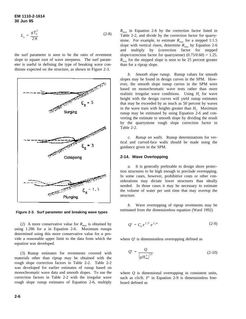
EM 1110-2-161430 Jun 95
(2-8)Lo
gT2p
2π
the surf parameter is seen to be the ratio of revetmentslope to square root of wave steepness. The surf param-eter is useful in defining the type of breaking wave con-ditions expected on the structure, as shown in Figure 2-3.
Figure 2-3. Surf parameter and breaking wave types
(2) A more conservative value forRmax is obtained byusing 1.286 fora in Equation 2-6. Maximum runupsdetermined using this more conservative value fora pro-vide a reasonable upper limit to the data from which theequation was developed.
(3) Runup estimates for revetments covered withmaterials other than riprap may be obtained with therough slope correction factors in Table 2-2. Table 2-2was developed for earlier estimates of runup based onmonochromatic wave data and smooth slopes. To use thecorrection factors in Table 2-2 with the irregular waverough slope runup estimates of Equation 2-6, multiply
Rmax in Equation 2-6 by the correction factor listed inTable 2-2, and divide by the correction factor for quarry-stone. For example, to estimateRmax for a stepped 1:1.5slope with vertical risers, determineRmax by Equation 2-6and multiply by (correction factor for steppedslope/correction factor for quarrystone) (0.75/0.60) = 1.25.Rmax for the stepped slope is seen to be 25 percent greaterthan for a riprap slope.
b. Smooth slope runup.Runup values for smoothslopes may be found in design curves in the SPM. How-ever, the smooth slope runup curves in the SPM werebased on monochromatic wave tests rather than morerealistic irregular wave conditions. UsingHs for waveheight with the design curves will yield runup estimatesthat may be exceeded by as much as 50 percent by wavesin the wave train with heights greater thanHs. Maximumrunup may be estimated by using Equation 2-6 and con-verting the estimate to smooth slope by dividing the resultby the quarrystone rough slope correction factor inTable 2-2.
c. Runup on walls. Runup determinations for ver-tical and curved-face walls should be made using theguidance given in the SPM.
2-14. Wave Overtopping
a. It is generally preferable to design shore protec-tion structures to be high enough to preclude overtopping.In some cases, however, prohibitive costs or other con-siderations may dictate lower structures than ideallyneeded. In those cases it may be necessary to estimatethe volume of water per unit time that may overtop thestructure.
b. Wave overtopping of riprap revetments may beestimated from the dimensionless equation (Ward 1992)
(2-9)Q′ C0 eC1F′ eC2m
whereQ′ is dimensionless overtopping defined as
(2-10)Q′ Q
gH 3mo
1/2
where Q is dimensional overtopping in consistent units,such as cfs/ft.F′ in Equation 2-9 is dimensionless free-board defined as
2-6

EM 1110-2-161430 Jun 95
Table 2-2Rough Slope Runup Correction Factors (Carstea et al. 1975b)
Armor Type Slope (cot θ)Relative SizeH / Kr
a,bCorrection Factorr
Quarrystone 1.5 3 to 4 0.60
Quarrystone 2.5 3 to 4 0.63
Quarrystone 3.5 3 to 4 0.60
Quarrystone 5 3 0.60
Quarrystone 5 4 0.68
Quarrystone 5 5 0.72
Concrete Blocksc Any 6b 0.93
Stepped slope with vertical risers 1.5 1 ≤ Ho’/Krd 0.75
Stepped slope with vertical risers 2.0 1 ≤ Ho’/Krd 0.75
Stepped slope with vertical risers 3.0 1 ≤ Ho’/Krd 0.70
Stepped slope with rounded edges 3.0 1 ≤ Ho’/Krd 0.86
Concrete Armor Units
Tetrapods random two layers 1.3 to 3.0 - 0.45
Tetrapods uniform two layers 1.3 to 3.0 - 0.51
Tribars random two layers 1.3 to 3.0 - 0.45
Tribars uniform one layer 1.3 to 3.0 - 0.50
a Kr is the characteristic height of the armor unit perpendicular to the slope. For quarrystone, it is the nominal diameter; for armor units,the height above the slope.b Use Ho’ for ds/Ho’ > 3; and the local wave height, Hs for ds/Ho’ ≤ 3.c Perforated surfaces of Gobi Blocks, Monoslaps, and concrete masonry units placed hollows up.d Kr is the riser height.
(2-11)F′ F
H 2moLo
1/3
where F is dimensional freeboard (vertical distance ofcrest above swl). The remaining terms in Equation 2-9are m (cotangent of revetment slope) and the regressioncoefficientsC0, C1, andC2 defined as
(2-12)
C0 0.4578
C1 29.45
C2 0.8464
The coefficients listed above were determined for dimen-sionless freeboards in the range 0.25 <F′ < 0.43, andrevetment slopes of 1:2 and 1:3.5.
c. Overtopping rates for seawalls are complicated bythe numerous shapes found on the seawall face plus the
variety of fronting berms, revetments, and steps. Infor-mation on overtopping rates for a range of configurationsis available in Ward and Ahrens (1992). For bulkheadsand simple vertical seawalls with no fronting revetmentand a small parapet at the crest, the overtopping rate maybe calculated from
(2-13)Q′ C0 exp
C1F′ C2
Fds
where Q′ is defined in Equation 2-10,F′ is defined inEquation 2-11,ds is depth at structure toe, and the regres-sion coefficients are defined by
(2-14)
C0 0.338
C1 7.385
C2 2.178
2-7

EM 1110-2-161430 Jun 95
For other configurations of seawalls, Ward and Ahrens(1992) should be consulted, or physical model tests shouldbe performed.
2-15. Stability and Flexibility
Structures can be built by using large monolithic massesthat resist wave forces or by using aggregations of smallerunits that are placed either in a random or in awell-ordered array. Examples of these are large rein-forced concrete seawalls, quarrystone or riprap revet-ments, and geometric concrete block revetments. Themassive monoliths and interlocking blocks often exhibitsuperior initial strength but, lacking flexibility, may notaccommodate small amounts of differential settlement ortoe scour that may lead to premature failure. Randomlyplaced rock or concrete armor units, on the other hand,experience settlement and readjustment under wave attack,and, up to a point, have reserve strength over designconditions. They typically do not fail catastrophically ifminor damages are inflicted. The equations in thischapter are suitable for preliminary design for majorstructures. However, final design will usually requireverification of stability and performance by hydraulicmodel studies. The design guidance herein may be usedfor final design for small structures where the conse-quences of failure are minor. For those cases, projectfunds are usually too limited to permit model studies.
2-16. Armor Unit Stability
a. The most widely used measure of armor unitstability is that developed by Hudson (1961) which isgiven in Equation 2-15:
(2-15)W
γr H 3
KD
γr
γw
1
3
cotθ
where
W = required individual armor unit weight, lb (orW50
for graded riprap)
γr = specific weight of the armor unit, lb/ft3
H = monochromatic wave height
KD= stability coefficient given in Table 2-3
γw = specific weight of water at the site (salt or fresh)
θ = is structure slope (from the horizontal)
Stones within the cover layer can range from 0.75 to1.25 W as long as 50 percent weigh at leastW and thegradation is uniform across the structure’s surface. Equa-tion 2-15 can be used for preliminary and final designwhen H is less than 5 ft and there is no major overtop-ping of the structure. For larger wave heights, modeltests are preferable to develop the optimum design.Armor weights determined with Equation 2-15 for mono-chromatic waves should be verified during model testsusing spectral wave conditions.
b. Equation 2-15 is frequently presented as a stabi-lity formula with Ns as a stability number. RewritingEquation 2-15 as
(2-16)Ns
H
Wγr
1/3
γr
γw
1
it is readily seen that
(2-17)Ns KD cotθ 1/3
By equating Equations 2-16 and 2-17,W is readilyobtained.
c. For irregular wave conditions on revetments ofdumped riprap, the recommended stability number is
(2-18)Nsz 1.14 cot1/6θ
where Nsz is the zero-damage stability number, and thevalue 1.14 is obtained from Ahrens (1981b), which rec-ommended a value of 1.45 and usingHs with Equation 2-16, then modified based on Broderick (1983), whichfound usingH10 (10 percent wave height, or average ofhighest 10-percent of the waves) in Equation 2-16 pro-vided a better fit to the data. Assuming a Rayleigh waveheight distribution,H10 ≈ 1.27 Hs. BecauseHs is morereadily available thanH10, the stability number in Equa-tion 2-17 was adjusted (1.45/1.27 = 1.14) to allowHs tobe used in the stability equation while providing the moreconservative effect of usingH10 for the design.
d. Stability equations derived from an extensiveseries of laboratory tests in The Netherlands were pre-sented in van der Meer and Pilarczyk (1987) and van der
2-8

EM 1110-2-161430 Jun 95
Table 2-3Suggested Values for Use In Determining Armor Weight (Breaking Wave Conditions)
Armor Unit n1 Placement Slope (cot θ) KD
Quarrystone
Smooth rounded 2 Random 1.5 to 3.0 1.2
Smooth rounded >3 Random 1.5 to 3.0 1.6
Rough angular 1 Random 1.5 to 3.0 Do Not Use
Rough angular 2 Random 1.5 to 3.0 2.0
Rough angular >3 Random 1.5 to 3.0 2.2
Rough angular 2 Special2 1.5 to 3.0 7.0 to 20.0
Graded riprap3 24 Random 2.0 to 6.0 2.2
Concrete Armor Units
Tetrapod 2 Random 1.5 to 3.0 7.0
Tripod 2 Random 1.5 to 3.0 9.0
Tripod 1 Uniform 1.5 to 3.0 12.0
Dolos 2 Random 2.0 to 3.05 15.06
1 n equals the number of equivalent spherical diameters corresponding to the median stone weight that would fit within the layer thickness.2 Special placement with long axes of stone placed perpendicular to the slope face. Model tests are described in Markle and David-son (1979).3 Graded riprap is not recommended where wave heights exceed 5 ft.4 By definition, graded riprap thickness is two times the diameter of the minimum W50 size.5 Stability of dolosse on slope steeper than 1 on 2 should be verified by model tests.6 No damage design (3 to 5 percent of units move). If no rocking of armor (less than 2 percent) is desired, reduce KD by approximately50 percent.
Meer (1988a, 1988b). Two stability equations were pre-sented. For plunging waves,
(2-19)Ns 6.2P 0.18
S
N
0.2
ξ0.5z
and for surging or nonbreaking waves,
(2-20)Ns 1.0P 0.13
S
N
0.2
cotθ ξPz
where
P = permeability coefficient
S = damage level
N = number of waves
P varies from P = 0.1 for a riprap revetment over animpermeable slope toP = 0.6 for a mound of armor stonewith no core. For the start of damageS = 2 for revetment
slopes of 1:2 or 1:3, orS = 3 for revetment slopes of 1:4to 1:6. The number of waves is difficult to estimate, butEquations 2-19 and 2-20 are valid forN = 1,000 toN =7,000, so selecting 7,000 waves should provide a conser-vative estimate for stability. For structures other thanriprap revetments, additional values ofP and S are pre-sented in van der Meer (1988a, 1988b).
e. Equations 2-19 and 2-20 were developed fordeepwater wave conditions and do not include a wave-height truncation due to wave breaking. van der Meertherefore recommends a shallow water correction given as
(2-21)Ns (shallow water)
1.40Hs
H2
Ns (deep water)
whereH2 is the wave height exceeded by 2 percent of thewaves. In deep water,H2 ≈ 1.40 Hs , and there is nocorrection in Equation 2-21.
2-9
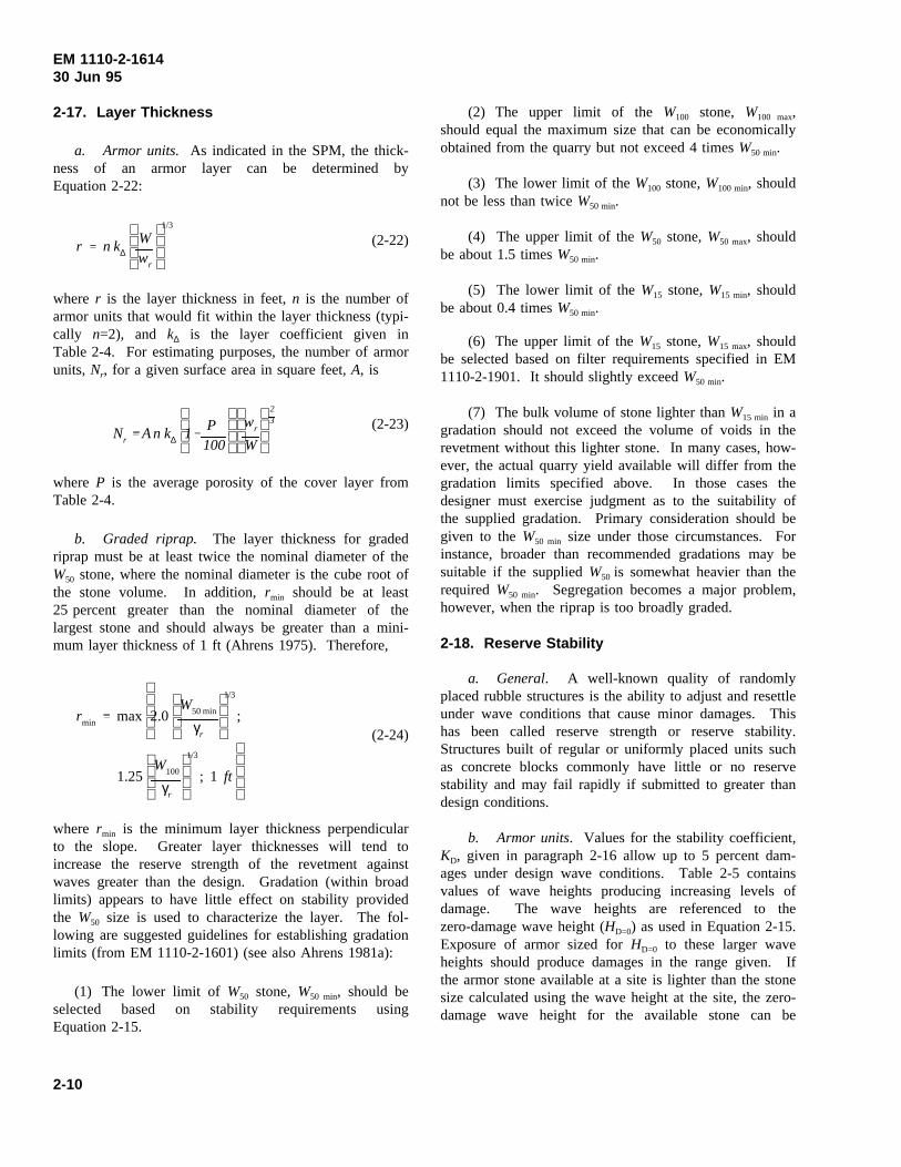
EM 1110-2-161430 Jun 95
2-17. Layer Thickness
a. Armor units. As indicated in the SPM, the thick-ness of an armor layer can be determined byEquation 2-22:
(2-22)r n k∆
Wwr
1/3
where r is the layer thickness in feet,n is the number ofarmor units that would fit within the layer thickness (typi-cally n=2), and k∆ is the layer coefficient given inTable 2-4. For estimating purposes, the number of armorunits, Nr, for a given surface area in square feet,A, is
(2-23)Nr A n k∆
1P100
wr
W
23
where P is the average porosity of the cover layer fromTable 2-4.
b. Graded riprap. The layer thickness for gradedriprap must be at least twice the nominal diameter of theW50 stone, where the nominal diameter is the cube root ofthe stone volume. In addition,rmin should be at least25 percent greater than the nominal diameter of thelargest stone and should always be greater than a mini-mum layer thickness of 1 ft (Ahrens 1975). Therefore,
(2-24)rmin max
2.0
W50 min
γr
1/3
;
1.25
W100
γr
1/3
; 1 ft
where rmin is the minimum layer thickness perpendicularto the slope. Greater layer thicknesses will tend toincrease the reserve strength of the revetment againstwaves greater than the design. Gradation (within broadlimits) appears to have little effect on stability providedthe W50 size is used to characterize the layer. The fol-lowing are suggested guidelines for establishing gradationlimits (from EM 1110-2-1601) (see also Ahrens 1981a):
(1) The lower limit of W50 stone,W50 min, should beselected based on stability requirements usingEquation 2-15.
(2) The upper limit of the W100 stone, W100 max,should equal the maximum size that can be economicallyobtained from the quarry but not exceed 4 timesW50 min.
(3) The lower limit of theW100 stone,W100 min, shouldnot be less than twiceW50 min.
(4) The upper limit of theW50 stone,W50 max, shouldbe about 1.5 timesW50 min.
(5) The lower limit of theW15 stone,W15 min, shouldbe about 0.4 timesW50 min.
(6) The upper limit of theW15 stone,W15 max, shouldbe selected based on filter requirements specified in EM1110-2-1901. It should slightly exceedW50 min.
(7) The bulk volume of stone lighter thanW15 min in agradation should not exceed the volume of voids in therevetment without this lighter stone. In many cases, how-ever, the actual quarry yield available will differ from thegradation limits specified above. In those cases thedesigner must exercise judgment as to the suitability ofthe supplied gradation. Primary consideration should begiven to theW50 min size under those circumstances. Forinstance, broader than recommended gradations may besuitable if the suppliedW50 is somewhat heavier than therequiredW50 min. Segregation becomes a major problem,however, when the riprap is too broadly graded.
2-18. Reserve Stability
a. General. A well-known quality of randomlyplaced rubble structures is the ability to adjust and resettleunder wave conditions that cause minor damages. Thishas been called reserve strength or reserve stability.Structures built of regular or uniformly placed units suchas concrete blocks commonly have little or no reservestability and may fail rapidly if submitted to greater thandesign conditions.
b. Armor units. Values for the stability coefficient,KD, given in paragraph 2-16 allow up to 5 percent dam-ages under design wave conditions. Table 2-5 containsvalues of wave heights producing increasing levels ofdamage. The wave heights are referenced to thezero-damage wave height (HD=0) as used in Equation 2-15.Exposure of armor sized forHD=0 to these larger waveheights should produce damages in the range given. Ifthe armor stone available at a site is lighter than the stonesize calculated using the wave height at the site, the zero-damage wave height for the available stone can be
2-10
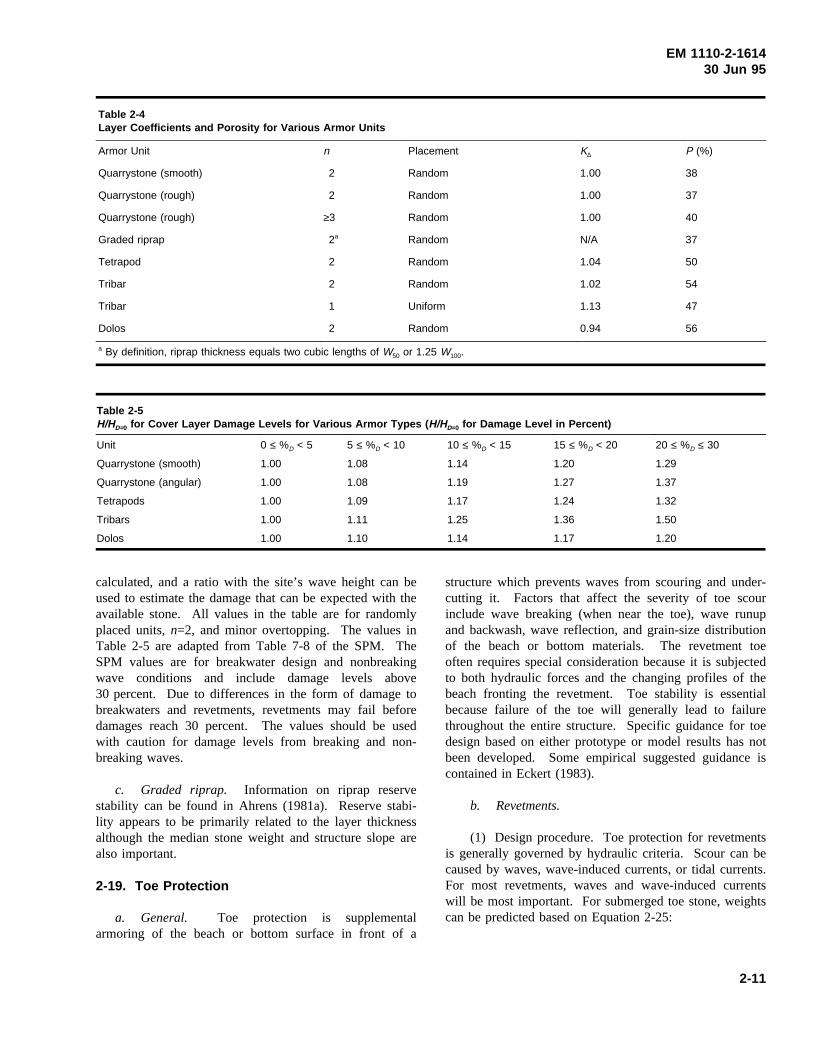
EM 1110-2-161430 Jun 95
Table 2-4Layer Coefficients and Porosity for Various Armor Units
Armor Unit n Placement K∆ P (%)
Quarrystone (smooth) 2 Random 1.00 38
Quarrystone (rough) 2 Random 1.00 37
Quarrystone (rough) ≥3 Random 1.00 40
Graded riprap 2a Random N/A 37
Tetrapod 2 Random 1.04 50
Tribar 2 Random 1.02 54
Tribar 1 Uniform 1.13 47
Dolos 2 Random 0.94 56
a By definition, riprap thickness equals two cubic lengths of W50 or 1.25 W100.
Table 2-5H/HD=0 for Cover Layer Damage Levels for Various Armor Types ( H/HD=0 for Damage Level in Percent)
Unit 0 ≤ %D < 5 5 ≤ %D < 10 10 ≤ %D < 15 15 ≤ %D < 20 20 ≤ %D ≤ 30
Quarrystone (smooth) 1.00 1.08 1.14 1.20 1.29
Quarrystone (angular) 1.00 1.08 1.19 1.27 1.37
Tetrapods 1.00 1.09 1.17 1.24 1.32
Tribars 1.00 1.11 1.25 1.36 1.50
Dolos 1.00 1.10 1.14 1.17 1.20
calculated, and a ratio with the site’s wave height can beused to estimate the damage that can be expected with theavailable stone. All values in the table are for randomlyplaced units,n=2, and minor overtopping. The values inTable 2-5 are adapted from Table 7-8 of the SPM. TheSPM values are for breakwater design and nonbreakingwave conditions and include damage levels above30 percent. Due to differences in the form of damage tobreakwaters and revetments, revetments may fail beforedamages reach 30 percent. The values should be usedwith caution for damage levels from breaking and non-breaking waves.
c. Graded riprap. Information on riprap reservestability can be found in Ahrens (1981a). Reserve stabi-lity appears to be primarily related to the layer thicknessalthough the median stone weight and structure slope arealso important.
2-19. Toe Protection
a. General. Toe protection is supplementalarmoring of the beach or bottom surface in front of a
structure which prevents waves from scouring and under-cutting it. Factors that affect the severity of toe scourinclude wave breaking (when near the toe), wave runupand backwash, wave reflection, and grain-size distributionof the beach or bottom materials. The revetment toeoften requires special consideration because it is subjectedto both hydraulic forces and the changing profiles of thebeach fronting the revetment. Toe stability is essentialbecause failure of the toe will generally lead to failurethroughout the entire structure. Specific guidance for toedesign based on either prototype or model results has notbeen developed. Some empirical suggested guidance iscontained in Eckert (1983).
b. Revetments.
(1) Design procedure. Toe protection for revetmentsis generally governed by hydraulic criteria. Scour can becaused by waves, wave-induced currents, or tidal currents.For most revetments, waves and wave-induced currentswill be most important. For submerged toe stone, weightscan be predicted based on Equation 2-25:
2-11

EM 1110-2-161430 Jun 95
(2-25)Wmin
γr H 3
N 3s
γr
γw
1
3
where Ns is the design stability number for rubble toeprotection in front of a vertical wall, as indicated in theSPM (see Figure 2-7). For toe structures exposed towave action, the designer must select either Equation 2-15which applies at or near the water surface or Equation 2-25 above. It should be recognized that Equation 2-25yields a minimum weight and Equation 2-15 yields amedian weight. Stone selection should be based on theweight gradations developed from each of the stoneweights. The relative importance of these factors dependson the location of the structure and its elevation withrespect to low water. When the toe protection is forscour caused by tidal or riverine currents alone, thedesigner is referred to EM 1110-2-1601. Virtually nodata exist on currents acting on toe stone when they are aproduct of storm waves and tidal or riverine flow. It isassumed that the scour effects are partially additive. Inthe case of a revetment toe, some conservatism is pro-vided by using the design stability number for toe protec-tion in front of a vertical wall as suggested above.
(2) Suggested toe configurations. Guidance containedin EM 1110-2-1601 which relates to toe design con-figurations for flood control channels is modified forcoastal revetments and presented in Figure 2-4. This isoffered solely to illustrate possible toe configurations.Other schemes known to be satisfactory by the designerare also acceptable. Designs I, II, IV, and V are for up tomoderate toe scour conditions and construction in the dry.Designs III and VI can be used to reduce excavationwhen the stone in the toe trench is considered sacrificialand will be replaced after infrequent major events. Athickened toe similar to that in Design III can be used forunderwater construction except that the toe stone is placedon the existing bottom rather than in an excavated trench.
c. Seawalls and bulkheads.
(1) General considerations. Design of toe pro-tection for seawalls and bulkheads must consider geotech-nical as well as hydraulic factors. Cantilevered, anchored,or gravity walls each depend on the soil in the toe areafor their support. For cantilevered and anchored walls,this passive earth pressure zone must be maintained forstability against overturning. Gravity walls resist slidingthrough the frictional resistance developed between thesoil and the base of the structure. Overturning is resisted
by the moment of its own weight supported by the zoneof bearing beneath the toe of the structure. Possible toeconfigurations are shown in Figure 2-5.
(2) Seepage forces. The hydraulic gradients ofseepage flows beneath vertical walls can significantlyincrease toe scour. Steep exit gradients reduce the neteffective weight of the soil, making sediment movementunder waves and currents more likely. This seepage flowmay originate from general groundwater conditions, waterderived from wave overtopping of the structure, or fromprecipitation. A quantitative treatment of these factors ispresented in Richart and Schmertmann (1958).
(3) Toe apron width. The toe apron width willdepend on geotechnical and hydraulic factors. The pas-sive earth pressure zone must be protected for a sheet-pilewall as shown in Figure 2-6. The minimum width, B,from a geotechnical perspective can be derived using theRankine theory as described in Eckert (1983). In thesecases the toe apron should be wider than the product ofthe effective embedment depth and the coefficient ofpassive earth pressure for the soil. Using hydraulic con-siderations, the toe apron should be at least twice theincident wave height for sheet-pile walls and equal to theincident wave height for gravity walls. In addition, theapron should be at least 40 percent of the depth at thestructure,ds. Greatest width predicted by these geotech-nical and hydraulic factors should be used for design. Inall cases, undercutting and unraveling of the edge of theapron must be minimized.
(4) Toe stone weight. Toe stone weight can bepredicted based on Figure 2-7 (from Brebner andDonnelly 1962)). A design wave betweenH1 and H10 issuggested. To apply the method assume a value ofdt thedistance from the still water level to the top of the toe. Ifthe resulting stone size and section geometry are notappropriate, a differentdt should be tried. Using themedian stone weight determined by this method, theallowable gradation should be approximately 0.5 to1.5 W.
2-20. Filters
A filter is a transitional layer of gravel, small stone, orfabric placed between the underlying soil and the struc-ture. The filter prevents the migration of the fine soilparticles through voids in the structure, distributes theweight of the armor units to provide more uniform set-tlement, and permits relief of hydrostatic pressures withinthe soils. For areas above the waterline, filters also
2-12
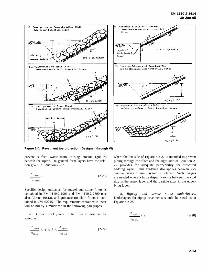
EM 1110-2-161430 Jun 95
Figure 2-4. Revetment toe protection (Designs I through VI)
prevent surface water from causing erosion (gullies)beneath the riprap. In general form layers have the rela-tion given in Equation 2-26:
(2-26)d15upper
d85under
< 4
Specific design guidance for gravel and stone filters iscontained in EM 1110-2-1901 and EM 1110-2-2300 (seealso Ahrens 1981a), and guidance for cloth filters is con-tained in CW 02215. The requirements contained in thesewill be briefly summarized in the following paragraphs.
a. Graded rock filters. The filter criteria can bestated as:
(2-27)d15 filter
d85soil
< 4 to 5 <d15 filter
d15soil
where the left side of Equation 2-27 is intended to preventpiping through the filter and the right side of Equation 2-27 provides for adequate permeability for structuralbedding layers. This guidance also applies between suc-cessive layers of multilayered structures. Such designsare needed where a large disparity exists between the voidsize in the armor layer and the particle sizes in the under-lying layer.
b. Riprap and armor stone underlayers.Underlayers for riprap revetments should be sized as inEquation 2-28,
(2-28)d15 armor
d85 filter
< 4
2-13
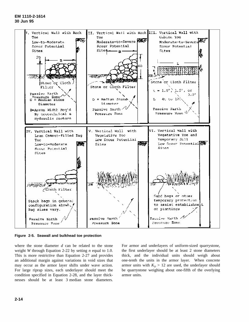
EM 1110-2-161430 Jun 95
Figure 2-5. Seawall and bulkhead toe protection
where the stone diameterd can be related to the stoneweight W through Equation 2-22 by settingn equal to 1.0.This is more restrictive than Equation 2-27 and providesan additional margin against variations in void sizes thatmay occur as the armor layer shifts under wave action.For large riprap sizes, each underlayer should meet thecondition specified in Equation 2-28, and the layer thick-nesses should be at least 3 median stone diameters.
For armor and underlayers of uniform-sized quarrystone,the first underlayer should be at least 2 stone diametersthick, and the individual units should weigh aboutone-tenth the units in the armor layer. When concretearmor units withKD > 12 are used, the underlayer shouldbe quarrystone weighing about one-fifth of the overlyingarmor units.
2-14
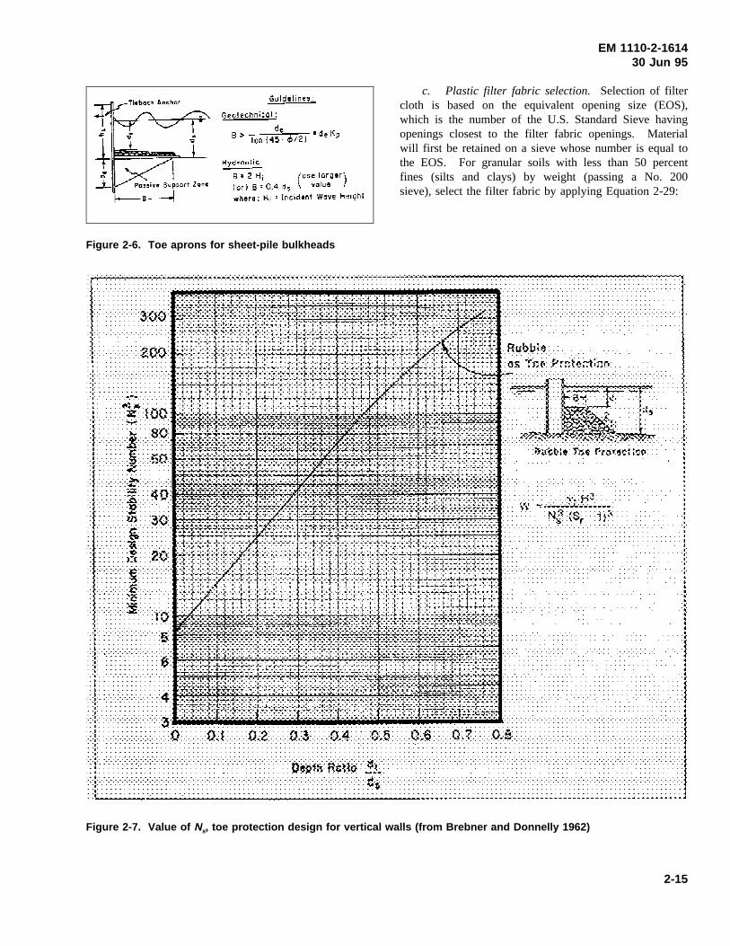
EM 1110-2-161430 Jun 95
Figure 2-6. Toe aprons for sheet-pile bulkheads
c. Plastic filter fabric selection. Selection of filtercloth is based on the equivalent opening size (EOS),which is the number of the U.S. Standard Sieve havingopenings closest to the filter fabric openings. Materialwill first be retained on a sieve whose number is equal tothe EOS. For granular soils with less than 50 percentfines (silts and clays) by weight (passing a No. 200sieve), select the filter fabric by applying Equation 2-29:
Figure 2-7. Value of Ns, toe protection design for vertical walls (from Brebner and Donnelly 1962)
2-15

EM 1110-2-161430 Jun 95
(2-29)EOS sieve
d85 soil
≤ 1
For other soils, the EOS should be no larger than theopenings in a No. 70 sieve. Furthermore, no fabricshould be used whose EOS is greater than 100, and noneshould be used alone when the underlying soil containsmore than 85 percent material passing a No. 200 sieve.In those cases, an intermediate sand layer may provide thenecessary transition layer between the soil and the fabric.Finally, the gradient ratio of the filter fabric is limited toa maximum value of three. That is, based on a headpermeability test, the hydraulic gradient through thefabric and the 1 in. of soil adjacent to the fabric (i1)divided by the hydraulic gradient of the 2 in. of soilbetween 1 and 3 in. above the fabric (i2) is:
(2-30)Gradient ratioi1i2
≤ 3
Studies such as those in Chen et al. (1981) suggest thatthese filter cloth selection requirements may be somewhatrestrictive.
d. Filter fabric placement.Experience indicates thatsynthetic cloths can retain their strength even after longperiods of exposure to both salt and fresh water. Toprovide good performance, however, a properly selectedcloth should be installed with due regard for the followingprecautions. First, heavy armor units may stretch thecloth as they settle, eventually causing bursting of thefabric in tension. A stone bedding layer beneath armorunits weighing more than 1 ton for above-water work(1.5 tons for underwater construction) is suggested (Dun-ham and Barrett 1974), and multiple underlayers may beneeded under primary units weighing more than 10 tons.Filter guidance must be properly applied in these cases.Second, the filter cloth should not extend seaward of thearmor layer; rather, it should terminate a few feet land-ward of the armor layers as shown in Figure 2-8. Third,adequate overlaps between sheets must be provided. Forlightweight revetments this can be as little as 12 in. andmay increase to 3 ft for larger underwater structures.Fourth, sufficient folds should be included to eliminatetension and stretching under settlement. Securing pinswith washers is also advisable at 2-to 5-ft intervals alongthe midpoint of the overlaps. Last, proper stone place-ment requires beginning at the toe and proceeding up
Figure 2-8. Use of filter cloth under revetment and toeprotection stone
the slope. Dropping stone can rupture some fabrics evenwith free falls of only 1 ft, although Dunham and Barrett(1974) suggest that stones weighing up to 250 lb cansafely be dropped from 3 ft. Greater drop heights areallowable under water where blocks up to 1 ton can bedropped through water columns of at least 5 ft.
2-21. Flank Protection
Flank protection is needed to limit vulnerability of astructure from the tendency for erosion to continue aroundits ends. Return sections are generally needed at bothends to prevent this. Sheet-pile structures can often betied well into existing low banks, but the return sectionsof other devices such as rock revetments must usually beprogressively lengthened as erosion continues. Extensionof revetments past the point of active erosion should beconsidered but is often not feasible. In other cases, athickened end section, similar to toe protection, can beused when the erosion rate is mild.
2-22. Corrosion
Corrosion is a primary problem with metals in brackishand salt water, particularly in the splash zone where mate-rials are subjected to continuous wet-dry cycles. Mildcarbon steel, for instance, will quickly corrode in such
2-16

EM 1110-2-161430 Jun 95
conditions. Corrosion-resistant steel marketed undervarious trade names is useful for some applications.Aluminum sheetpiling can be substituted for steel in someplaces. Fasteners should be corrosion-resistant materialssuch as stainless or galvanized steel, wrought iron, ornylon. Various protective coatings such as coal-tar epoxycan be used to treat carbon steel. Care must always betaken to avoid contact of dissimilar metals (galvanic cou-ples). The more active metal of a galvanic couple tendsto act as an anode and suffers accelerated corrosion. Thegalvanic series of common metals in seawater is given inTable 2-6 (Uhlig 1971). This table can be used for esti-mating the corrosion potential of galvanic couples, but thecomplexity of corrosion processes makes it useful only asguide. For example, although aluminum and copper are
closer together on the table than aluminum and stainlesssteel, in actual practice polarization effects with stainlesssteel make it more compatible with aluminum than alumi-num copper couples. The Construction EngineeringResearch Laboratory (CERL) should be contacted wheneither performance or longevity is a significantrequirement.
2-23. Freeze-Thaw Cycles
Concrete should be designed for freeze-thaw resistance (aswell as chemical reactions with salt water), as concretemay seriously degrade in the marine environment. Guid-ance on producing suitable high quality concrete is pre-sented in EM 1110-2-2000 and Mather (1957).
Table 2-6Galvanic Series in Sea Water
MORE
ACTIVE
LESS
ACTIVE
MATERIAL MATERIAL (≈ ACTIVITY)
Magnesium Stainless steel - 304 AS
Stainless steel - 316 AS
Zinc Lead
Tin
Aluminum 52S4
Aluminum 4S Magnesium bronze
Aluminum 3S Naval brass
Aluminum 2S
Aluminum 53S-T Nickel AS
Yellow brass
Aluminum bronze
Red brass
Aluminum 17S-T Copper, silicon bronze
Aluminum 24S-T
Mild steel Composition G bronze
Wrought iron Composition M bronze
Cast iron Nickel PS
Stainless steel-410 AS
Stainless steel-304 PS
Stainless steel-316 PS
AS Active statePS Passive state
2-17
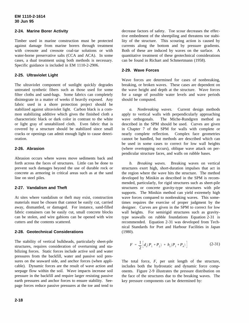
EM 1110-2-161430 Jun 95
2-24. Marine Borer Activity
Timber used in marine construction must be protectedagainst damage from marine borers through treatmentwith creosote and creosote coal-tar solutions or withwater-borne preservative salts (CCA and ACA). In somecases, a dual treatment using both methods is necessary.Specific guidance is included in EM 1110-2-2906.
2-25. Ultraviolet Light
The ultraviolet component of sunlight quickly degradesuntreated synthetic fibers such as those used for somefilter cloths and sand-bags. Some fabrics can completelydisintegrate in a matter of weeks if heavily exposed. Anyfabric used in a shore protection project should bestabilized against ultraviolet light. Carbon black is a com-mon stabilizing additive which gives the finished cloth acharacteristic black or dark color in contrast to the whiteor light gray of unstabilized cloth. Even fabric that iscovered by a structure should be stabilized since smallcracks or openings can admit enough light to cause deteri-oration.
2-26. Abrasion
Abrasion occurs where waves move sediments back andforth across the faces of structures. Little can be done toprevent such damages beyond the use of durable rock orconcrete as armoring in critical areas such as at the sandline on steel piles.
2-27. Vandalism and Theft
At sites where vandalism or theft may exist, constructionmaterials must be chosen that cannot be easily cut, carriedaway, dismantled, or damaged. For instance, sand-filledfabric containers can be easily cut, small concrete blockscan be stolen, and wire gabions can be opened with wirecutters and the contents scattered.
2-28. Geotechnical Considerations
The stability of vertical bulkheads, particularly sheet-pilestructures, requires consideration of overturning and sta-bilizing forces. Static forces include active soil and waterpressures from the backfill, water and passive soil pres-sures on the seaward side, and anchor forces (when appli-cable). Dynamic forces are the result of wave action andseepage flow within the soil. Wave impacts increase soilpressure in the backfill and require larger resisting passiveearth pressures and anchor forces to ensure stability. See-page forces reduce passive pressures at the toe and tend to
decrease factors of safety. Toe scour decreases the effec-tive embedment of the sheetpiling and threatens toe stabi-lity of the structure. This scouring action is caused bycurrents along the bottom and by pressure gradients.Both of these are induced by waves on the surface. Aquantitative treatment of these geotechnical considerationscan be found in Richart and Schmertmann (1958).
2-29. Wave Forces
Wave forces are determined for cases of nonbreaking,breaking, or broken waves. These cases are dependent onthe wave height and depth at the structure. Wave forcesfor a range of possible water levels and wave periodsshould be computed.
a. Nonbreaking waves. Current design methodsapply to vertical walls with perpendicularly approachingwave orthogonals. The Miche-Rundgren method asdescribed in the SPM should be used. Curves are givenin Chapter 7 of the SPM for walls with complete ornearly complete reflection. Complex face geometriescannot be handled, but methods are described which canbe used in some cases to correct for low wall heights(where overtopping occurs), oblique wave attack on per-pendicular structure faces, and walls on rubble bases.
b. Breaking waves. Breaking waves on verticalstructures exert high, short-duration impulses that act inthe region where the wave hits the structure. The methoddeveloped by Minikin as described in the SPM is recom-mended, particularly, for rigid structures such as sheet-pilestructures or concrete gravity-type structures with pilesupports. The Minikin method can yield extremely highwave forces compared to nonbreaking waves. This some-times requires the exercise of proper judgment by thedesigner. Curves are given in the SPM to correct for lowwall heights. For semirigid structures such as gravity-type seawalls on rubble foundations Equation 2-31 isrecommended. Equation 2-31 was developed from Tech-nical Standards for Port and Harbour Facilities in Japan(1980).
(2-31)F12
ds P1 P2 hc P1 P4
The total force, F, per unit length of the structure,includes both the hydrostatic and dynamic force comp-onents. Figure 2-9 illustrates the pressure distribution onthe face of the structures due to the breaking waves. Thekey pressure components can be determined by:
2-18

EM 1110-2-161430 Jun 95
Figure 2-9. Breaking wave pressures on a vertical wall
(2-32)P1 α1 α2 γwHb
(2-33)P3 α3 P1
(2-34)P4
1hc
1.5Hb
P1
where
(2-35)α1 0.6 12
4πh/L
sinh 4πh/L
2
(2-36)α2 min
hb d
3hb
Hb
d
2
, 2dHb
(2-37)α3 1ds
h
1 1
cosh
2πhL
where
γw = specific weight of water
hc = height of crest of caisson above swl
d = depth at top of rubble mound
ds = depth at base of caisson
Hb = highest of the random waves breaking at a dis-tance of 5Hs seaward of the structure;Hs is thesignificant wave height of the design sea state
hb = water depth whereHb is determined
h = water depth at toe of compound breakwater
L = wave length calculated by linear wave theory atthe structure for wave period ofHs
As an example, for a vertical wall, 4.3 m (14 ft) highsited in sea water withds = 2.5 m (8.2 ft) on a bottomslope of 1:20 (m = 0.05) and experiencing wave crests atan interval of 10 sec, the force on the wall would bedetermined as follows:
Since there is no rubble-mound base, the water depthds = 2.5 m. Using a wave periodT = 10 sec and Fig-ure 7-4 of the SPM, the breaking wave height,Hb, isfound to be 3.2 m (10.5 ft). Without knowledge of thesignificant wave height,Hs, the breaking depth,hb, isdetermined directly by using SPM Figure 7-2, whichyields hb = 3.07 m (10 ft). The wave breaks at a distanceof 11.4 m (37 ft) [(3.07 - 2.5)/0.05] from the wall. UsingSPM Appendix C Table C-1, wave length,L, at ds =2.5 m is determined to be 48.7 m (160 ft). Then,α1, α2,and α3 are calculated to be 1.036, 0.101, and 0.950,respectively. Crest height,hc, is less than 1.5Hb
(1.8<4.8) and overtopping exists. The pressure com-ponentsP1, P3, andP4 are computed from the above equa-tions to be 36.4 kN/m2 (1,742.8 lb/ft2), 34.6 kN/m2 (16-56.6 lb/ft2), and 22.8 kN/m2 (1,091.7 lb/ft2), respectively.Equation 3-31 yields a total horizontal force due to thebreaking wave of 142 kN/m2 (6,799 lb/ft2).
c. Broken waves.Some structures are placed in aposition where only broken waves can reach them. Inthose cases approximate broken wave force,F, per unitlength of structure can be estimated (Camfield 1991) byEquation 2-38:
(2-38)F 0.18 γ H 2b
1X1 m
RA
2
whereγ is the specific weight of water and m is the beachslope (m=tan θ). Other variables of Equation 2-38,Hb,X1, and RA are defined in Figure 2-10. The adjusted
2-19

EM 1110-2-161430 Jun 95
Figure 2-10. Wave pressure from broken waves
wave runup height,RA, which would occur if the wall wasnot present can be determined by using Equation 2-6(rough slopes) or following the methods described inChapter 2-13 for smooth slopes or slopes covered withrubble other than quarrystone. If accurate force estimatesare needed, model tests are required.
For example, deepwater waves areHmo = 0.91 m (3 ft)and Tp = 12 sec. The waves cross 3.05 m (10 ft) of cob-ble shoreline with a slope of m = 0.10 before impactingon a wall. From Figure 7-3 in SPM (1984), breakingwave heightHb is 2.05 m (6.75 ft). Using Equation 2-7we find ξ = 1.57, and Equation 2-6 yieldsRmax = 1.36 m(4.48 ft). UseRmax for the adjusted runup,RA, in Equation2-38 to find the force per unit length of wall is 4.58 kN/mlength of wall (317 lb/ft length of wall).
2-30. Impact Forces
Impact forces constitute an important design considerationfor shore structures because high winds can propel smallpleasure craft, barges, and floating debris and cause greatimpact forces on a structure. If site or functional con-ditions require the inclusion of impact forces in thedesign, other measures should be taken to limit the depthof water against the face of the structure by providing arubble-mound absorber against the face of the wall or apartly submerged sill seaward of the structure that willground floating masses and eliminate the potential hazard.In many areas impact hazards may not occur, but wherethe potential exists (as for harbor structures), impactforces should be evaluated from impulse-momentumconsiderations.
2-31. Ice Forces
a. General. Ice can affect marine structures in anumber of ways. Moving surface ice can cause sig-nificant crushing and bending forces as well as large
impact loadings. Vertical forces can be caused by theweight of ice on structures at low tide and by buoyantuplift at high tide of ice masses frozen to structural ele-ments. EM 1110-2-1612 should be reviewed beforedesigning any structure subject to ice forces.
b. Damages.Ice formations can cause considerabledamage to shoreline at some points, but their net effectsare largely beneficial. Spray “freezes” on banks andstructures and covers them with a protective layer of ice.Ice piled on shore by wind and wave action does not gen-erally cause serious damage to beaches, bulkheads, orprotective riprap, but it provides additional protectionagainst severe winter waves. Some abrasion of timber orconcrete structures may be caused, and individual mem-bers may be broken or bent by the weight of the ice mass.Piling is sometimes slowly pulled by the repeated liftingeffect of ice frozen to the piles or attached members, suchas wales, and then it is forced upward by a rise in waterstage or wave action. Superstructure damages also some-times occur due to ice.
2-32. Hydraulic Model Tests
The guidance contained in this manual is suitable forpreliminary design of all coastal structures and for finaldesign of minor or inexpensive works where the conse-quences of failure are not serious. For most cases, how-ever, the final design should be verified through a modeltesting program. Design deficiencies can be identifiedwith such models, and design economics may be achievedwhich more than offset the cost of the study. Hudson etal. (1979) contains information on current hydraulic mod-eling techniques.
2-33. Two-Dimensional Models
Two-dimensional tests are conducted in wave tanks orflumes. Such tests are useful for evaluating toe stone andarmor stability, wave runup heights, and overtoppingpotential. Generated waves may be either monochromaticor irregular depending on the capabilities of the equip-ment. Monochromatic waves represent the simplest case,and they form the basis for the majority of current designguidance. Irregular waves, on the other hand, are a closerrepresentation of actual prototype conditions. Their use,however, adds to the complexity of a modeling program.
2-34. Three-Dimensional Models
Three-dimensional models are built in large shallowbasins where processes such as wave refraction and dif-fraction are of interest. They can also lead to qualitative
2-20

EM 1110-2-161430 Jun 95
results for sediment transport studies. However, theseissues are generally unimportant for the design of revet-ments, seawalls, and bulkheads; therefore, the use ofthree-dimensional models would be unusual for suchstructures.
2-35. Previous Tests
WES has conducted a number of two- and three-dimen-sional model studies of site-specific projects. Details onfive of these are given below. Units are given in proto-type dimensions.
a. Fort Fisher NC (1982). Important features were(Markle 1982):
Scale 1:24
Waves Heights of 5.5 to 17.2 ftPeriods of 8, 10, and 12 sec
Depths 12, 14.7, 17, and 19 ft
Revetment slope: 1:2
The toe consisted of 8,919-lb StaPods on bedding stone.The sizes of the armor units were 5,900 lb (speciallyplaced) and 8,900 lb (randomly placed). These werestable and undamaged in depths to 14.7 ft. At depths of17 and 19 ft, considerable damages were experienced, butno failures occurred.
b. El Morro Castle, San Juan, PR (1981).Impor-tant features were (Markle 1981):
Scale 1:38.5
Waves Heights of 10 to 23.3 ftPeriods of 15 and 17 sec (northrevetment)
Heights of 2.5 to 10.5 ftPeriods of 9, 15, and 17 sec (westrevetment)
18 and 19.9 ft (north revetment)
13 and 14.9 ft (west revetment)
Revetment slope: 1:3
The toe protection was generally a 10-ft-wide armor stoneblanket except in certain areas of the north revetment
where a low-crested breakwater was used. Armor stonesizes were 10,300 lb (west revetment), 24,530 lb (northrevetment), and 9,360 lb (north revetment behind break-water). All armor stone was randomly placed.
c. Generalized harbor site for the U.S. Navy(1966). Important features were (USAEWES 1966):
Scale 1:15Waves Heights of 5, 10, 15, and 20 ft
10-sec periods
Depths 20 to 40 ft
Revetment slope: 1:5
No toe protection was provided (the toe extended to theflume bottom). Stable rock sizes and values ofKd werereported for several wave conditions.
d. Railroad fills at Ice Harbor and John DayReservoirs (1962). The tests were conducted for bothriprap stability and runup. Important features were(USAEWES 1962):
Scale 1:12
Waves Height of 2.4 to 2.6 ftPeriods of 3, 4, 5, 6, and sec
Depths 20 to 40 ft
Revetment slope: 1:2
No toe protection was provided. The stableW50 sizeswere
W50 H300 lb 3.0 to 3.4 ft500 lb 2.0 to 4.1 ft700 lb 3.9 to 4.9 ft
e. Levees in Lake Okeechobee, FL (1957).Thetests were conducted for both wave runup and overtop-ping. Important features were (USAEWES 1957):
Scale 1:30 and 1:17
Waves Heights of 4, 6, 8, and 12 ftPeriods of 4.5 to 7 sec
Depths 10, 17.5, and 25 ft
2-21

EM 1110-2-161430 Jun 95
Revetment slope: 1:3, 1:6, andcomposite slopes
No toe protection was considered. The tests produced aseries of runup and overtopping volume curves.
2-22

EM 1110-2-161430 Jun 95
Chapter 3Revetments
3-1. General
A revetment is a facing of erosion resistant material, suchas stone or concrete, that is built to protect a scarp,embankment, or other shoreline feature against erosion.The major components of a revetment are the armor layer,filter, and toe (Figure 3-1). The armor layer provides thebasic protection against wave action, while the filter layersupports the armor, provides for the passage of waterthrough the structure, and prevents the underlying soilfrom being washed through the armor. Toe protectionprevents displacement of the seaward edge of therevetment.
Figure 3-1. Typical revetment section
3-2. Armor Types
Revetment armoring may range from rigid to flexibletypes. Concrete slabs-on-grade is an example of theformer, while riprap and quarrystone are examples of thelatter. Rigid armors tend to be more massive but aregenerally unable to accommodate settlement or adjust-ments of the underlying materials. Flexible armor is con-structed with lighter individual units that can toleratevarying amounts of displacement and shifting. Details ofindividual armor types are presented in Appendix B. Theindividual alternatives discussed in Appendix B are sum-marized in Figure 3-2.
3-3. Design Procedure Checklist
The usual steps needed to design an adequate revetmentare:
a. Determine the water level range for the site(paragraph 2-5).
b. Determine the wave heights (paragraphs 2-6 to2-11).
c. Select suitable armor alternatives to resist thedesign wave (Appendix B).
d. Select armor unit size (paragraphs 2-15 to 2-18).
e. Determine potential runup to set the crest eleva-tion (paragraphs 2-12 and 2-13).
f. Determine amount of overtopping expected forlow structures (paragraph 2-14).
g. Design underdrainage features if they arerequired.
h. Provide for local surface runoff and overtoppingrunoff, and make any required provisions for other drain-age facilities such as culverts and ditches.
i. Consider end conditions to avoid failure due toflanking (paragraph 2-21.
j. Design toe protection (paragraph 2-19).
k. Design filter and underlayers (paragraph 2-20).
l. Provide for firm compaction of all fill and back-fill materials. This requirement should be included on theplans and in the specifications. Also, due allowance forcompaction must be made in the cost estimate.
m. Develop cost estimate for each alternative.
3-1
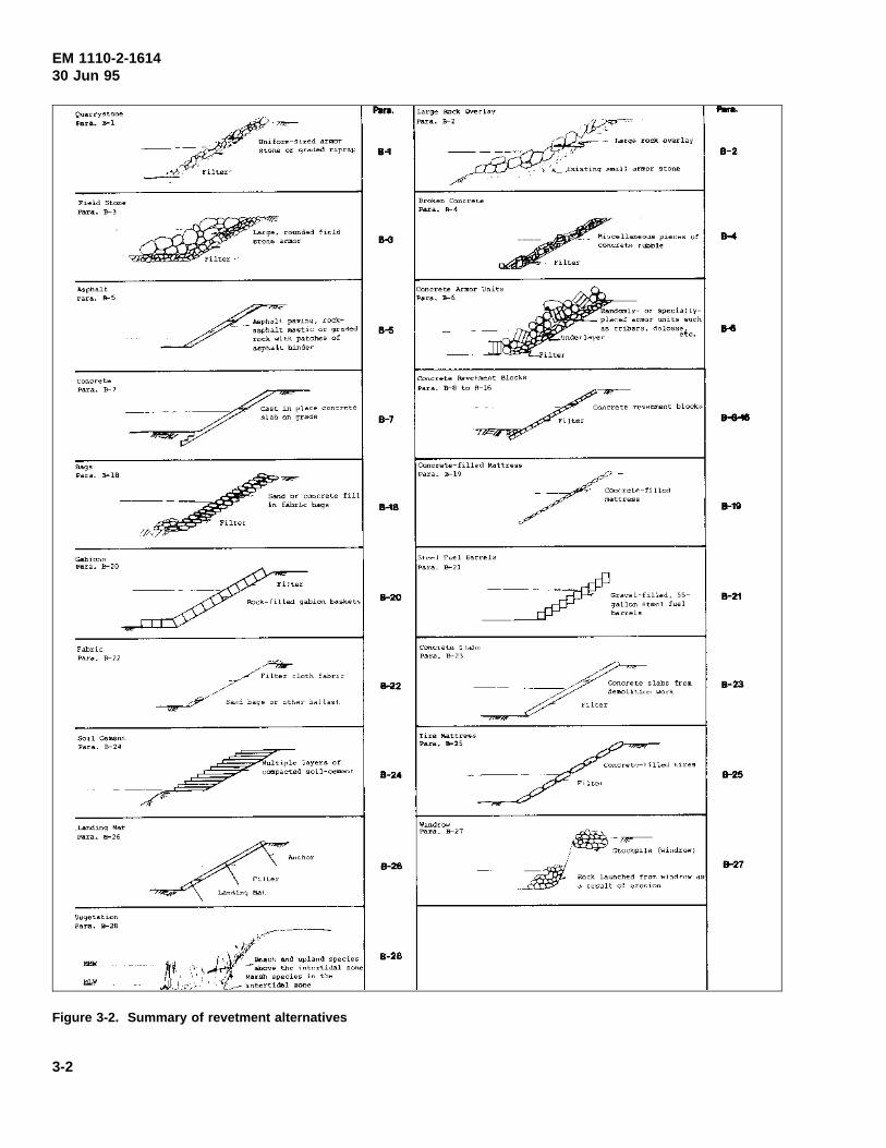
EM 1110-2-161430 Jun 95
Figure 3-2. Summary of revetment alternatives
3-2

EM 1110-2-161430 Jun 95
Chapter 4Seawalls
4-1. General
A seawall is a massive structure that is designed primarilyto resist wave action along high value coastal property.Seawalls may be either gravity- or pile-supported struc-tures. Common construction materials are either concreteor stone. Seawalls can have a variety of face shapes(Figure 4-1).
Figure 4-1. Typical concrete seawall sections
4-2. Concrete Seawalls
These structures are often pile-supported with sheetpilecutoff walls at the toe to prevent undermining. Additionalrock toe protection may also be used. The seaward facemay be stepped, vertical, or recurved. Typical examplesare described in Appendix C and shown in Figure 4-2.
4-3. Rubble-Mound Seawalls
These are designed like breakwaters using a rock size thatwill be stable against the design wave. Stability isdetermined using the method described in paragraphs 2-15to 2-18. An example is described in Appendix C andshown in Figure 4-2.
4-4. Design Procedure Checklist
The most critical design elements are a secure foundationto minimize settlement and toe protection to preventundermining. Both of these are potential causes of failureof such walls. The usual steps needed to develop anadequate seawall design follow.
a. Determine the water level range for the site(paragraph 2-5).
b. Determine the wave heights (paragraphs 2-6 to2-11).
c. Select suitable seawall configurations(Appendix C).
d. Design pile foundations using EM 1110-2-2906.
e. Select a suitable armor unit type and size (rubbleseawalls and toe protection) (paragraphs 2-15 to 2-18).
f. Determine the potential runup to set the crestelevation (paragraphs 2-12 to 2-13).
g. Determine the amount of overtopping expectedfor low structures (paragraph 2-14).
h. Design underdrainage features if they arerequired.
Figure 4.2. Summary of seawall alternatives
4-1

EM 1110-2-161430 Jun 95
i. Provide for local surface runoff and overtoppingand runoff, and make any required provisions for otherdrainage facilities such as culverts and ditches.
j. Consider end conditions to avoid failure due toflanking (paragraph 2-21).
k. Design the toe protection (paragraph 2-19).
l. Des ign the f i l t e r and unde r l aye rs(paragraph 2-20).
m. Provide for firm compaction of all fill and back-fill materials. This requirement should be included on theplans and in the specifications, and due allowance forcompaction must be made in the cost estimate.
n. Develop cost estimate for each alternative.
4-2

EM 1110-2-161430 Jun 95
Chapter 5Bulkheads
5-1. General
Bulkheads are retaining walls whose primary purpose is tohold or prevent the backfill from sliding while providingprotection against light-to-moderate wave action. Theyare used to protect eroding bluffs by retaining soil at thetoe, thereby increasing stability, or by protecting the toefrom erosion and undercutting. They are also used forreclamation projects, where a fill is needed seaward of theexisting shore, and for marinas and other structures wheredeep water is needed directly at the shore.
5-2. Structural Forms
Bulkheads are either cantilevered or anchored sheetpilingor gravity structures such as rock-filled timber cribbing.Cantilevers require adequate embedment for stability andare usually suitable where wall heights are low. Toescour reduces their effective embedment and can lead tofailure. Anchored bulkheads are usually used where
greater heights are necessary. Such bulkheads alsorequire adequate embedment for stability but are less sus-ceptible to failure due to toe scour. Gravity structureseliminate the expense of pile driving and can often beused where subsurface conditions hinder pile driving.These structures require strong foundation soils to ade-quately support their weight, and they normally do notsufficiently penetrate the soil to develop reliable passiveresisting forces on the offshore side. Therefore, gravitystructures depend primarily on shearing resistance alongthe base of the structure to support the applied loads.Gravity bulkheads also cannot prevent rotational slides inmaterials where the failure surface passes beneath thestructure. Details of typical bulkheads are presented inAppendix D and are summarized in Figure 5-1.
5-3. Design Procedure Checklist
The bulkhead design procedure is similar to that presentedfor seawalls in paragraph 4-4, except that Appendix D isused for examples of typical bulkheads. In addition, toeprotection should be designed using geotechnical andhydraulic conditions, including wave action and currentscour.
5-1

EM 1110-2-161430 Jun 95
Figure 5-1. Summary of bulkhead alternatives
5-2

EM 1110-2-161430 Jun 95
Chapter 6Environmental Impacts
6-1. General
Coastal shore protection structures are intended toimprove stability by reducing the rate of change in adynamic coastal system. The environmental impacts maybe short-term during construction operations or long-termbecause of the presence of the structures. The potentialenvironmental impacts, which are similar for each of thecoastal shore protection structures featured in this manual,are briefly discussed below. More detailed informationmay be found in Barnard (1978), Carstea et al. (1975a;1975b), Ford et al. (1983), Hurme (1979), Johnson andDeWitt (1978), and Mulvihille et al. (1980).
6-2. Physical Impacts
The littoral system at the site of a structure is alwaysmoving toward a state of dynamic equilibrium where theability of waves, currents, and winds to move sediment ismatched by the available supply of littoral materials.When there is a deficiency of material moving within asystem, the tendency will be for erosion at some locationto supply the required material. Once a structure hasbeen built along a shoreline, the land behind it will nolonger be vulnerable to erosion (assuming proper functionof the structure), and the contribution of littoral materialto the system will be diminished along the affected shore-line. The contribution formerly made by the area mustnow be supplied by the adjoining areas. This can havemixed environmental impacts. The reduction in sedimen-tation due to decreased erosion may be viewed as a posi-tive effect in many cases. Erosion that is shifted to otherareas may result in a negative impact in those locations.Some vertical structures such as bulkheads may causeincreased wave reflection and turbulence with a subse-quent loss of fronting beach. This is usually viewed as anegative impact. In all cases, the overall situation and thevarious impacts that result must be evaluated carefully toidentify potential changes in the shore and barrier islandprocesses.
6-3. Water Quality Impacts
Impacts of coastal shore protection structures on waterquality can be addressed in two categories:
a. Increased suspended solids during construction.
b. Altered circulation caused by structures.
Construction of shore protection structures can result inincreased suspended solid loads within the adjoining waterbody. Recent research results indicate that the traditionalfears of water quality degradation caused from suspendedsolids during in-water construction activities are for themost part unfounded. It has been demonstrated that theincreased concentration of suspended solids is generallyconfined to the immediate vicinity of the constructionactivity and dissipates rapidly at the completion of theoperation. Although these are generally short-termimpacts, construction activities should be designed tominimize generation of suspended solids. The dispersionof near-surface suspended solids can be controlled, to acertain extent, by placing a silt curtain around the con-struction activity. Under quiescent current conditions(less than 0.1 knot) the suspended solids level in the watercolumn outside the curtain can be reduced by as much as80 to 90 percent. Silt curtains are not recommendedwhere currents exceed 1 knot. Steps must be taken alsoto avoid the introduction of toxic or other harmful sub-stances resulting from construction materials, equipmentleaks, spills, and other accidents. Project specificationsshould contain provisions that address these concerns.Structures may influence water quality by altering circula-tion patterns. Modification in circulation may result inchanges in the spatial distribution of water quality con-stituents, differences in the flushing rates of potentialcontaminants, and changes in the scour patterns and depo-sition of sediments. Environmental assessment of theeffects on circulation should initially emphasize the physi-cal parameters such as salinity, temperature, and velocity.If minimal changes occur in these parameters, then it canbe assumed that the chemical characteristics of the systemwill not be significantly modified. Prediction of changesin circulation and its effect on the physical parameters canbe achieved through comparison with existing projects,physical model studies, and numerical simulation.
6-4. Biological Impacts
A wide variety of living resources is present in coastalshore protection project areas and includes species ofcommercial, recreational, and aesthetic importance.Because shore protection projects exist in arctic, temper-ate, and tropical climates, biological impacts will gen-erally be highly site-specific and depend upon the natureand setting of the project. The environmental impacts onthe benthic communities resulting from suspended solidsin the water around shore protection construction are forthe most part minor. This is particularly true in the surfzone on open coast beaches where rapid natural changesand disturbances are normal and where survival of thebenthic community requires great adaptability. Placement
6-1
EM 1110-2-161430 Jun 95
of coastal shore protection structures requires an initialdisturbance of the benthic substrate, but it results in theformation of a new substrate composed of structural mate-rial and stability of the sediments adjacent to the structure.In many locations the placement of these structures pro-vides new habitat not available otherwise.
6-5. Short-term Impacts
Short-term impacts are usually associated with the actualconstruction phase of the project. The actual time is typi-cally short (measured in days and weeks) and, therefore,can be scheduled to minimize negative impacts. Trans-portation of material to the site, preparation and construc-tion using heavy equipment, and back filling and gradingwill cause temporary air and noise pollution close to thesite. Nesting, resting, or feeding waterfowl and fish andother wildlife will be disrupted. Projects should be timed,if possible, to avoid waterfowl and turtle nesting periodsand fish spawning periods. Temporarily reduced waterquality, discussed in paragraph 6-3, may have biologicalimpacts. However, if the bank is severely eroding or isheavily developed these impacts may be minimal by com-parison. Siltation of offshore sea grasses or corals as theresult of construction, dredging, and filling at the site maybe of short or long duration depending on the compositionof the sediment, the currents, and circulation patterns atthe site and the locations of these specific resources.Construction impacts at sites with a high percentage offine material and nearby sea grass bed or corals could behigh and require special planning and precautions such assilt curtains. Dredging activities may attract opportunisticforaging fish as well as temporarily destroy benthic habi-tats. Resuspension of bottom sediments may interferewith respiration and feeding, particularly of nonmotilebottom dwellers. Motile organisms will temporarily fleethe disturbed area.
6-6. Long-term Impacts
Long-term effects vary considerably depending upon thelocation, design and material used in the structure. Theimpact of a vertical steel sheet bulkhead located at meanlow water in a freshwater marsh will be considerablydifferent from a rubble-reveted bank in an industrializedharbor. Vertical structures in particular may accelerateerosion of the foreshore and create unsuitable habitat formany bottom species in front of the structure as the resultof increased turbulence and scour from reflected waveenergy. On the other hand, rubble toe protection or ariprap revetment extending down into the water at a slop-ing angle will help dissipate wave energy and will providereef habitat for many desirable species. Bulkheads and
revetments can reduce the area of the intertidal zone andeliminate the important beach or marsh habitat betweenthe aquatic and upland environment. This can also resultin the loss of spawning, nesting, breeding, feeding, andnursery habitat for some species. However, birds such aspelicans might benefit. A number of design alternativesshould be considered to maximize biological benefits andminimize negative impacts. Table 6-1 summarizes designconsiderations for improving the environmental quality ofthese structures.
6-7. Socioeconomic and Cultural Impacts
Secondary impacts are often more controversial than theprimary impacts on air, water, noise, and the biota. Landuse patterns will often change as the result of construc-tion. However, only two elements normally are directlyconsidered in the design of the structure itself. The struc-ture should be sited to avoid known archaeological orother cultural sites. Secondly, the structure should bedesigned to be aesthetically pleasing. Coastal shore pro-tection structures change the appearance of the coastline.The visual impact of a structure is dependent on how wellthe structure blends with its surroundings. The impor-tance of visual impacts is related to the number ofviewers, their frequency of viewing, and the overall con-text. For example, the appearance of a structure in aheavily used urban park is more critical than a structure inan industrial area or an isolated setting. Aesthetic impactscan be adverse or beneficial depending on preconstructionconditions and the perception of the individual observer.Coastal shore protection structures offer a visual contrastto the natural coastal environment. However, manyobservers prefer a structure to erosion damage. Mostcoastal shore protection structures improve access to thewater’s edge for recreation and sightseeing.
6-8. Evaluation of Alternatives
Comparison and evaluation of coastal shore protectionalternatives involves examination of economic, engineer-ing, and environmental aspects. Alternatives are eval-uated according to how well they meet specified projectobjectives. Examples of environmental objectives includepreservation, protection, and enhancement of aestheticresources, fish and wildlife habitat, and water quality.Evaluation of the short- and long-term impacts of coastalshore protection structures requires comparison ofwith-project and without-project conditions. Recognizingthe dynamic nature of the coastal system, a forecast mustbe made of future environmental conditions without theproject. These predicted conditions are then compared
6-2

EM 1110-2-161430 Jun 95
6-3

EM 1110-2-161430 Jun 95
with the expected conditions resulting from each alterna-tive. Environmental features should be integral parts ofthe project, not additions made late in design or afterward.
6-4

Maritime Unit Shore Protection: Breakwater
CHAPTER 3
SHORE PROTECTION: BREAKWATER
3.0 INRODUCTION
Aim of this paper is to outline breakwaters, considering their:
- Functions - Types - Design Guidelines - Construction
Breakwaters are structures which provide protection to the harbours and structures
such as sea intakes against wave action. Basic principles are the same for revetments which are basically one sided
breakwaters, normally with no overtopping. Whilst breakwaters are basically simple in form and can be defined with a few
drawings and short specifications, they can be multi-million dollar structures with very serious repercussions on failure. 3.1 FUNCTIONS
Breakwaters are constructed for the following purposes:
i. To provide a protection against waves for harbour facilities by decreasing the wave powers into the sheltered area.
ii. To maintain navigational depths for ship going into the harbour by protecting
from the intrusion of littoral drift (shoaling).
iii. Control the magnitude and direction of currents
iv. Stabilize the location of an entrance
v. Coastal Protection (revetments)
vi. Often have combination of functions.
51
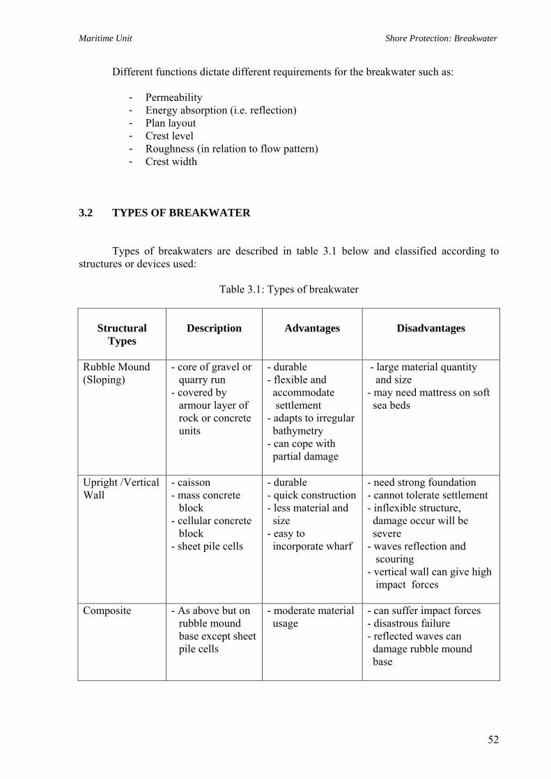
Maritime Unit Shore Protection: Breakwater
Different functions dictate different requirements for the breakwater such as:
- Permeability - Energy absorption (i.e. reflection) - Plan layout - Crest level - Roughness (in relation to flow pattern) - Crest width
3.2 TYPES OF BREAKWATER
Types of breakwaters are described in table 3.1 below and classified according to structures or devices used:
Table 3.1: Types of breakwater
Structural Types
Description
Advantages
Disadvantages
Rubble Mound (Sloping)
- core of gravel or quarry run
- covered by armour layer of rock or concrete units
- durable - flexible and accommodate settlement
- adapts to irregular bathymetry - can cope with partial damage
- large material quantity and size - may need mattress on soft sea beds
Upright /Vertical Wall
- caisson - mass concrete
block - cellular concrete
block - sheet pile cells
- durable - quick construction - less material and size - easy to incorporate wharf
- need strong foundation - cannot tolerate settlement - inflexible structure, damage occur will be severe - waves reflection and scouring - vertical wall can give high impact forces
Composite - As above but on rubble mound base except sheet pile cells
- moderate material usage
- can suffer impact forces - disastrous failure - reflected waves can damage rubble mound base
52

Maritime Unit Shore Protection: Breakwater
Resonant Breakwater
- Series of rectangular basins built at harbour entrance
- Not a common structural form
Rigid Floating Breakwater
- Usually temporary – large floating body such as ship or pontoon anchored in position
- easy installation - can be relocated - independent of depth - little space usage
- ineffective for long period waves
- can resonate on some frequencies
Flexible Floating Breakwater
- Temporary flexible buoyant floating devices such as car tyres with some flotation-lashed together
- quick fabrication and inexpensive
- independent of depth
- easily relocated
- ineffective on long waves
Air Bubble Curtain
- Submerged pipeline discharging air to cause currents in the water and waves to break
- no space - no shipping restriction
- quick construction
- high energy usage - only good on very short waves
- can be block by sediments
As a general rule:
- Rubble mound breakwaters most durable and best suited to heavy wave attack. - Vertical wall breakwaters have use where limited space or material available,
particularly in deep water. - Floating breakwater or bubble curtain only affect short period waves and have
no effect on sediment movement.
53
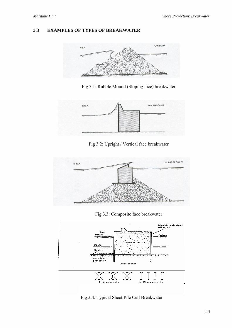
Maritime Unit Shore Protection: Breakwater
3.3 EXAMPLES OF TYPES OF BREAKWATER
Fig 3.1: Rubble Mound (Sloping face) breakwater
Fig 3.2: Upright / Vertical face breakwater
Fig 3.3: Composite face breakwater
Fig 3.4: Typical Sheet Pile Cell Breakwater
54

Maritime Unit Shore Protection: Breakwater
3.4 DESIGN GUIDELINES 3.4.1 Principle of Design
In the design of breakwaters, the following matters shall be examined:
a. Layout of the breakwater b. Influence of the breakwater on site selection c. Design conditions and parameters d. Structural types breakwater e. Design method f. Execution method g. Construction cost
3.4.2 Layout of Breakwater
In determine of the layout of breakwaters, the following matters shall be examined:
a. Environmental conditions b. Calmness in the harbour c. Ease of ship manoeuvrability d. Water quality in the harbour e. Construction cost and maintenance cost f. Future plans of the port and harbour
3.4.3 Influence of Breakwaters on Site Selection
The breakwaters may have considerable influence on the site selection because of the relatively high cost of constructing breakwaters. In order to minimize breakwater costs, the following factors should be considered:
The total length of breakwater should be as small as possible.
i. Port site selection and breakwater alignment for narrow wave sector (Fig 3.5)
On a coast where the waves come from narrow sector only, minimum length is obtained if the port is placed at a headland with an offset of the coastline sufficiently large to allow for the necessary port area, at the same time as one relatively short breakwater can reach sufficient depth, by taking advantage of the curvature of the contour lines.
55

Maritime Unit Shore Protection: Breakwater
Fig 3.5: Breakwater alignment for narrow wave sector
ii. Port site selection and breakwater alignment for wide wave sector (Fig 3.6)
On the coast where the wave sector is wide the most favourable site would be between two neighbouring headlands particularly if the necessary dredging inside the port area can take place in loose sediments
Fig 3.6: Breakwater alignment for wide wave sector iii. Port site selection and breakwater alignment for rocky shoal and coastal ridge
(Fig 3.7)
Fig 3.7: Breakwater alignment for rocky shoal and coastal ridge
56

Maritime Unit Shore Protection: Breakwater
3.4.4 Design Conditions and Parameters
To determine the design conditions and parameters for the design of a breakwater system, basically there are 3 main areas to be covered:
a. Define performance requirement or functional requirement
• wave levels and associated frequencies that can be tolerated within harbour area • sizes and manoeuvrability of vessels to use harbour • whether regular dredging can be tolerated • whether overtopping and some wave transmission can be tolerated
b. Collect environmental data
• Bathymetry • Water level variation (tide and storm surge) • Wave heights and directions • Winds • Currents • Sediment transport and shoreline stability • Foundation conditions
c. Determine availability of material
3.4.5 Phases (Work Flow)
The number of phases in the design of breakwater depends upon its magnitude. For major breakwaters there are naturally more and more complicated steps in the design than for small traditional breakwaters. The following is a fairly complete list of the steps required for a major breakwater;
a. Establish design organization b. Site selection c. Compilation of existing climatic such as;
• Oceanographic data • Hydrographic data • Geologic data
d. Preliminary estimate of wave conditions e. First tentative layout f. Wave recording during at least one year g. Recording of long waves during periods where long wave effects may be expected h. Tide recording for say two months if no tidal data is available i. Topographic and hydrographic survey j. Sedimentation study k. Environmental study
57

Maritime Unit Shore Protection: Breakwater
l. Soil investigations m. Search for construction materials n. Hydraulic model test for determination of layout o. Choice of breakwater type p. Preliminary design of breakwater cross section q. Model test for optimization of cross section and end of breakwater r. Final detailed design
3.5 DESIGN OF A RUBBLE MOUND BREAKWATER
Having determined the performance criteria and gathered relevant data for the site, the design for breakwater can proceed:
• Preliminary design • Final design based on model study
Major aspects of the design are:
• The layout of the breakwater in order to achieve the specified performance of wave reduction, current realignment etc. for the protected area
• The cross section
3.5.1 Alignment
Can use wave diffraction calculation initially, but need to fine tune with a model study – either a physical or numerical model. 3.5.2 Cross Section
No codes available to determine for example the design wave height and loading as with a building code:
• At a particular site a range of structures can be build for a range of costs depending on the design wave height chosen and whether overtopping will be acceptable.
• Classic optimum design curve
o Curve 1 - construction cost o Curve 2 - capitalized maintenance cost o Curve 3 - total cost
58

Maritime Unit Shore Protection: Breakwater
• Clearly as design wave increases then probability of exceedance drops; but structure is larger with greater construction cost. Likelihood of damage in service is less and thus likelihood and cost of maintenance will decrease.
• Costs due to loss of facility usage must also be considered.
• Best to err on side of safety when designing breakwaters.
i. Assessment of Design Wave
Look at probability of exceedance of wave heights:
- Short Term (Micro) distribution - Long Term (Macro) distribution
a. Short term distribution
Single storm or record containing N waves can be characterised by Hs (significant wave height) (average of 1/3 highest waves – 13% exceedance). Fortunately the distribution of waves within the storm approximately follows the Rayleigh Distribution (theoretical model).
Thus for an arbitrary design wave height Hd the chance of exceedance by any given wave is: -
P(Hd) = 2
2⎥⎦
⎤⎢⎣
⎡−
s
d
HH
e
Values of P(Hd) vs s
d
HH
plot as a straight
P(Hd) %
Log
s
d
HH
line on log normal paper.
The chance that this wave is not exceeded is
1-P(Hd)
The chance that this wave is not exceeded in a series of N waves is
[l-P(Hd)]N
The chance that this wave (Hd) is exceeded at least once in a single storm of H waves is
E l = 1 - [1- P (Hd)]N
The Poisson approximation is
El = 1- e-N P(Hd)
Handy relationships based on the Rayleigh Distribution are _ _
59
Maritime Unit Shore Protection: Breakwater
Hs = 1.596 H H = average of all waves
Hs = 1.414 Hrms
b. Long Term Distribution
It is assumed that significant wave heights obey long term frequency distribution.
Wave height exceedance graph is a plot of significant wave height and probability of exceedance.
The probability of Hd occurring in any single storm characterised by Hsi is
E2i = P(Hsi)E1i
Overall chance that Hd is exceeded at least once in single storm period is
N E3 = Σ E2i (N is number of increments of Hs)
i=1
P(Hsi) is the probability of occurence of storm represented by significant wave height Hsi .
The chance that design wave height Hd is exceeded at least once during life span of structure
is P (Hd) = 1- (1-E3)M.L
M = number of storms per year L = structure design life in years.
Can work through for range of values of Hd to get plot of Hd versus P(Hd).
More realistic approach is to look at say maximum wave in 50 year storm as design wave.
- Acceptable level of probability of exceedance for Hd depends to some extent on the type of structure
• Need lower value when structure can be affected by a single wave -
e.g. a light tower or vertical breakwater
• Can tolerate higher value when need numerous repetitions for major damage as with rubble mound breakwater - with mound breakwaters, wave groups are important and Hs is a useful measure.
For the particular site - determine wave climate and wave height exceedance distribution
60

Maritime Unit Shore Protection: Breakwater
- If possible use wave records at site (swell and wind waves) (2 years +). - Otherwise use refracted/diffracted offshore waves (from wave atlas etc.). - Also determine local wind waves by hindcasting calculations -graphs in Shore
Protection Manual - for total fetch. Wind speed etc. - Must bear in mind the depth limitation for wave breaking - water levels
important (breaking reduces height but increases force). - Breaking and non-breaking wave Hb = 0.78d
Actual design wave chosen depends on
• Expected life of structure • Availability of construction material • Initial and maintenance costs
ii. Form of Mound Breakwaters
Cross section
Does not need to cap structure unless have traffic or artificial units to prevent overtopping.
If overtopping prevented can reduce size of lee side armour.
iii. Theoretical Stability Consideration
Several formulae developed to determine size of breakwater armour units.
most of form W = c H3
f ( α) W - armour stone weight H - wave height α - Slope of face c - coefficient dependent on both mass density of units and shape
IRRIBARREN in 1930’s looked at forces acting on an armour stone.
W
α
F P P - wave force F - friction W - weight
and developed expression for unit weight
61

Maritime Unit Shore Protection: Breakwater
W = ( )33
3
sin cos ααρ
+∆ fHN r
where N = coefficient based on stone type
ρr = mass density kg/m3 ∆ = relative density of stone in water
ρw = mass density of water f = friction coefficient
f not easy to interpret -varies with shape and method placement.
Also had problems that as 450 get ridiculously high values.
HUDSON modified Irribarren to
W = ( ) θρ
cot 1 3
3
−rD
r
SKH
W = mass of individual armour unit (kg)
= mass density of armour material (kg/m3) H = design wave height Sr = specific gravity of armour unit relative to water m P r/pw Θ = angle of side slope measured from horizontal in degrees KD = stability coefficient smooth rounded rock for breaking wave 1.2
smooth rounded rock for breaking wave 2.4 Pw = mass density of (sea) water = 1025 kg/m3
KD = stability coefficient depending on - armour shape
- slope - method of placement - breaking or non-breaking waves. - number of layers - position on structure (head or trunk). - note that ∆ = (Sr – 1)
KD values determined by model tests on various units under various conditions and range tabulated. Depends on way test is undertaken also.
Main weakness is that the only parameter that reflects on wave loading is H.
No consideration of wave period, angle of attack, storm duration. Wave grouping etc.
Interesting to look at significance of change in parameters in Hudson's formula on the resulting armour unit mass.
- 10 per cent increase in wave height gives a 30 per cent increase in armour unit
mass. - 10 per cent increase in stone density reduces mass by 30 per cent. - Reducing slope from 1 in 1.5 to 1 in 2 reduces I mass by 25 per cent.
62
Maritime Unit Shore Protection: Breakwater
Initially KD values were determined so as the structure was theoretically undamaged if wave height H was app1ied to units of weight H.
Then va1ues of KD were determined to a11ow for percentage of armour units dislodged i .e. certain damage percent 1evels.
Note that the actual performance of a breakwater cross-section and particularly the armour units is on1y indicated by these formula -must support findings at least with flume tests. Even tests not always reproduceable.
From the value of H for primary armour stone mass there are rules (based on test results) for determination of mass of secondary armour, underlayers, and core.
Search has been for armour units with KD larger than that for quarry rock.
- Great diversity of shapes - many patented.
Some KD values quoted are unrealistic.
However these units do have cost advantages where
- Local quarry rock is of poor quality - Cannot get local supply of large stones - KD values required in design are greater than available from quarry rock.
- iv. Beam Type Cross-Section
v. Optimising Design
- Considering initial cost and maintenance cost. Need to assess damage caused by wave conditions greater than represented by Hso -significant wave height causing zero damage.
a. Must have long term distribution of significant wave values.
b. Must relate variations in wave conditions (represented by Hs) to performance of structure .Hs is characteristic wave attacking the structure.
This impl1es that the known distribution of wave heights and periods are applied 1n flume tests. This enables us to determine Hso -max. wave height that can satisfy no damage criteria. When Hso exceeded -get movement of armour from positions which gives % damage. This is shown on page (10) Hs / Hso vs % damage. Collapse taken as 10~ damage (H/Hso -1.45). Armour unit mass determined from test as
63

Maritime Unit Shore Protection: Breakwater
W = 2.8(Hso)3
50
c. Must relate construction cost and Hso. Use simplified expression F1 = f(Hso) = 1320 Hso + 8620 [example only]
d. Must relate - expected damage
- Offshore conditions - Hso.
Get damage if Hs>Hso. Damage expected depends on probability of Hs > Hso.
S = 100 ∑ ∆P ∆W
Where S = capitalized value of total damage W= amount of damage associated with exceedence of Hso by ∆Hs which
occurs with probability each year of ∆P For life of 100 years or more.
δ = interest rate. Note that this method is only indicative.
Important to stress that formulae give a guide only. Need to test preliminary design of breakwater in flume and also if possible in basin. Need to look not only at single large waves but wave groups or close pairs of large wave than can swamp structure and pluck out armour units. Engineer should not leave test to laboratory technician -may never have been out of laboratory. Even testing can lead to varying results depending on laboratory technique.
e. Failure of breakwaters
Have been numerous failures of major breakwaters designed by experienced engineers. Typical failure modes:
1. Plucking out of armour units as a result of wave inertia and drag force plus uplift forces from seepage.
2. Damage to crest as result of overtopping.
3. Excessive loading from sequence of particularly large waves.
4. Failure of secondary armour by sliding.
5. Building up of seepage uplift forces –breakwater with fine core material most
susceptible.
64
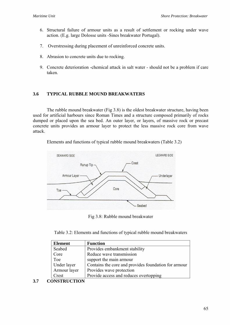
Maritime Unit Shore Protection: Breakwater
6. Structural failure of armour units as a result of settlement or rocking under wave action. (E.g. large Dolosse units -Sines breakwater Portugal).
7. Overstressing during placement of unreinforced concrete units.
8. Abrasion to concrete units due to rocking.
9. Concrete deterioration -chemical attack in salt water - should not be a problem if care
taken. 3.6 TYPICAL RUBBLE MOUND BREAKWATERS
The rubble mound breakwater (Fig 3.8) is the oldest breakwater structure, having been
used for artificial harbours since Roman Times and a structure composed primarily of rocks dumped or placed upon the sea bed. An outer layer, or layers, of massive rock or precast concrete units provides an armour layer to protect the less massive rock core from wave attack.
Elements and functions of typical rubble mound breakwaters (Table 3.2)
Fig 3.8: Rubble mound breakwater
Table 3.2: Elements and functions of typical rubble mound breakwaters
Element Function Seabed Core Toe Under layer Armour layer Crest
Provides embankment stability Reduce wave transmission support the main armour Contains the core and provides foundation for armour Provides wave protection Provide access and reduces overtopping
3.7 CONSTRUCTION
65

Maritime Unit Shore Protection: Breakwater
The design of breakwater must be kept simple because much of the breakwater will be constructed underwater
Construction must take into account
- local conditions - availability of materials - availability of construction plants
Overseas - heavy floating plants available including jack up barges, bottom
dump and side dump barges, etc
Australia - generally use land based plant unless breakwater is a major structure
• REMEMBER Sea is very powerful.
Construction method should take this into account.
Designer must have a specific method in mind to ensure that construction is practicable. Specifications and drawings can be developed around specific method but allow alternatives.
Methods of construction:
i. Nice to build in dry but seldom practical to cofferdam area and pump out.
ii. Common method in Australia is to end dump core and place armour with crane
or large hydraulic excavator.
- problems with congestion of plants on long breakwater - consider construction of second connection
iii. Stability during construction may dictate that cannot build up layer by layer –
problem with scour of finer material by waves and currents
Also - do not core advance too far ahead of armour
- design secondary armour to offer reasonable protection 3.8 REFERENCES
66

Maritime Unit Shore Protection: Breakwater
1. BS 6349 PT 7 – Design And Construction Of Breakwater
2. Technical Standards For Port and Harbour Facilities In Japan (OCDI)
3. Shore Protection Manual (US Army Corps Of Engineers)
67

Maritime Unit Shore Protection: Breakwater
APPENDIX
68
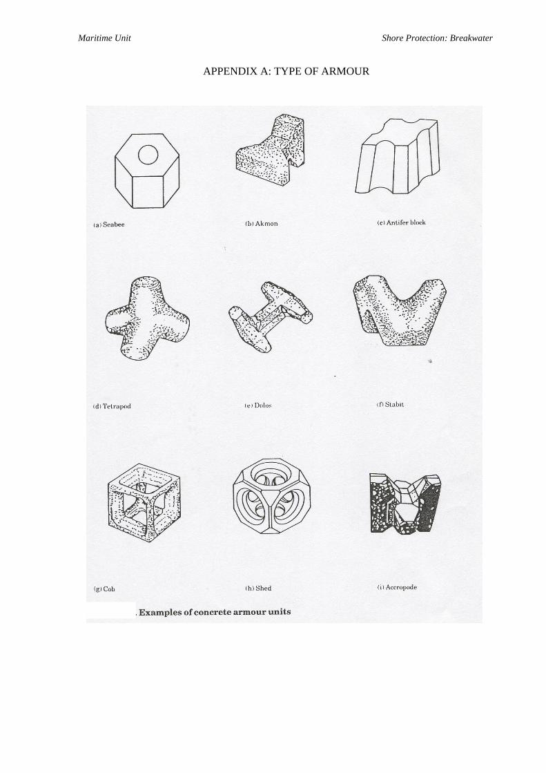
Maritime Unit Shore Protection: Breakwater
APPENDIX A: TYPE OF ARMOUR

Maritime Unit Shore Protection: Breakwater
2

Maritime Unit Shore Protection: Breakwater Maritime Unit Shore Protection: Breakwater
3
3

Maritime Unit Shore Protection: Breakwater
4
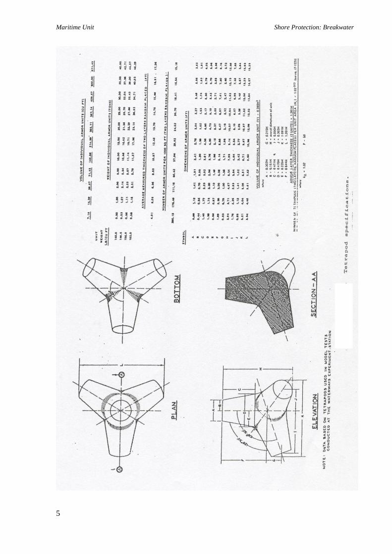
Maritime Unit Shore Protection: Breakwater
5
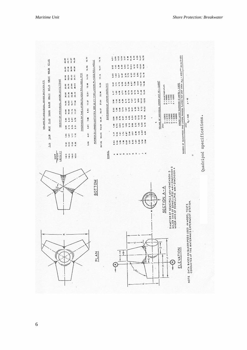
Maritime Unit Shore Protection: Breakwater
6

Maritime Unit Shore Protection: Breakwater
7

Maritime Unit Shore Protection: Breakwater
8

Maritime Unit Shore Protection: Breakwater Maritime Unit Shore Protection: Breakwater
9
9
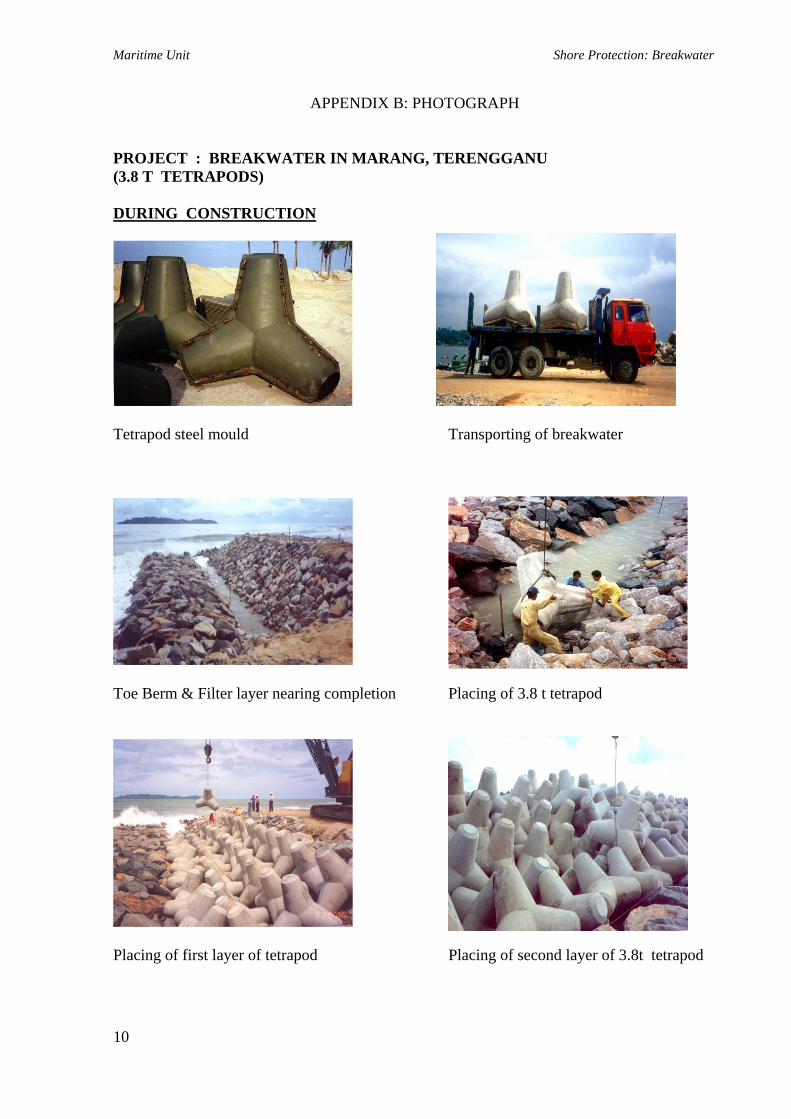
Maritime Unit Shore Protection: Breakwater
APPENDIX B: PHOTOGRAPH PROJECT : BREAKWATER IN MARANG, TERENGGANU (3.8 T TETRAPODS) DURING CONSTRUCTION
Tetrapod steel mould Transporting of breakwater
Toe Berm & Filter layer nearing completion Placing of 3.8 t tetrapod
Placing of first layer of tetrapod Placing of second layer of 3.8t tetrapod
10

Maritime Unit Shore Protection: Breakwater
COMPLETION OF 3.8 T TETRAPOD IN MARANG, TERENGGANU
11

Maritime Unit Shore Protection: Breakwater
APPENDIX C: SUPPLEMENTARY ATTACHMENTS
12

Maritime Unit Shore Protection: Breakwater
13

Maritime Unit Shore Protection: Breakwater
14

Maritime Unit Shore Protection: Breakwater
15

Maritime Unit Shore Protection: Breakwater
16
Maritime Unit Shore Protection: Coastal and Hydraulic Study
CHAPTER 4
COASTAL AND HYDRAULIC STUDY 4.0 PENGENALAN
Kajian Hakisan Pantai Negara merumuskan bahawa punca utama kejadian hakisan pantai dan kerosakan struktur marin yang serius adalah berpunca daripada lokasi penempatan, perancangan dan rekabentuk projek dan aktiviti pembangunan pantai yang kurang teratur. Akta Kualiti Alam Sekeliling (1974) dan Akta Kualiti Alam Sekeliling (Pindaan) (1985) merupakan undang-undang persekutuan yang mengenakan unsure kawalan perundangan atas kesemua aktiviti pembangunan dari segi kesan yang mungkin akan timbul terhadap alam sekeliling. Perintah Kualiti Alam Sekeliling (Aktiviti Yang Ditetapkan) 1987 menetapkan satu senarai aktiviti pembangunan yang mewajibkan penyerahan laporan Penilaian Kesan Kepada Alam Sekeliling (Laporan EIA) bagi aktiviti-aktiviti yang diwajibkan.(Rujuk Penilaian Kesan Kepada Alam Sekeliling (EIA) – Prosedur dan Keperluan Di Malaysia)
Sehubungan dengan itu, pada tahun 1997 kabinet telah meluluskan penggubalan ‘Garis Panduan Kawalan Hakisan Berikutan Dari Pembangunan Di Kawasan Pantai’ bertujuan bagi mengawal pembangunan di kawasan pantai.
Oleh yang demikian, Unit Maritim juga tidak terkecuali daripada Akta-Akta yang telah termaktub. Pelaksanaan Kajian Hidraulik di dalam skop kerja unit ini adalah berkaitan dengan kesan pembinaan struktur marin (jeti, pemecah ombak), penambakan atau pengorekan dan perlindungan pantai.
Rekabentuk kajian hidraulik perlu mengambil kira data-data alam sekitar seperti keadaan ombak, angin dan arus laut, keadaan topografi dan hidrografi dan pasang-surut air. Maklumat bagi data kualiti air akan diperolehi daripada hasil Kajian Kesan Alam Sekitar (EIA).
67

Maritime Unit Shore Protection: Coastal and Hydraulic Study
4.1 OBJEKTIF KAJIAN HIDRAULIK
Tujuan kajian hidraulik dilaksanakan disenaraikan seperti berikut :
1. Mengumpul dan menganalisa data sediada untuk menentukan samada boleh digunapakai dalam kajian tersebut.
2. Melaksanakan penganalisaan tapak kajian menggunakan model komputer yang
bagi mendapatkan situasi semasa dan impak yang terjadi disebabkan kepada kerja-kerja penambakan atau pengorekan pantai dan perlindungan pantai.
3. Mengenal pasti parameter rekabentuk yang akan digunakan terutama bagi kerja-
kerja penambakan atau pengorekan, perlindungan pantai dan pembinaan struktur (jeti, pemecah ombak).
4.2 SENARAI MODULE
Module hidraulik yang paling relevan dalam menilai impak sesuatu pembangunan adalah:
1. Module Hidrodinamik – meramalkan perubahan paras air dan respon aliran (misalnya keadaan halaju arus di pantai ‘nearshore’) akibat beberapa punca (pasang-surut dan ombak).
2. Module Pergerakan Lumpur/Pasir – meramalkan keadaan hakisan atau
pemendapan.
3. Module Perubahan Garis Pantai – meramalkan perubahan garis pantai. 4.3 SENARAI MODEL KOMPUTER
Pada masa sekarang terdapat beberapa model dalam pasaran yang boleh digunakan untuk menjalankan kajian hidraulik di kawasan pantai. Beberapa daripada model kajian hidraulik yang berada di pasaran adalah seperti berikut :
1. TELEMAC untuk mengkaji arus yang berpunca daripada pasang-surut.
68
Maritime Unit Shore Protection: Coastal and Hydraulic Study
2. MIKE 21 untuk mengkaji transformasi ombak, arus akibat ombak dan pasang-surut, ‘dispersion’, kualiti air, pergerakan lumpur dan pasir.
3. SURFACEWATER MODELLING SYSTEM (SMS) untuk mengkaji
transformasi ombak dan pasang-surut, kualiti air, pergerakan Lumpur dan pasir. Kelebihan : Dapat memaparkan perubahan permukaan arus dan aliran air berdasarkan kepada perubahan dasar pantai dalam bentuk satu, dua dan tiga dimensi.
4. UNIBEST untuk membuat ramalan terhadap perkembangan garis pantai dan mengira kadar pergerakan sedimen untuk kawasan pantai berpasir.
5. LITPACK untuk membuat ramalan terhadap arus’longshore’, pergerakan
sedimen ‘longhore’ dan perkembangan garis pantai untuk kawasan pantai berpasir.
6. DIVAST untuk mengkaji arus akibat ombak dan pasang surut serta dapat
menentukan pergerakan sedimen untuk bahan ‘cohesive’ dan ‘non-cohesive’.
7. REFRAC untuk digunakan menukar ombak di air yang dalam kepada keadaan ombak di air yang cetek.
Untuk permodelan hidrodinamik model yang dipilih seharusnya berupaya meramalkan
keadaan aliran arus akibat ombak dan pasang-surut. Walaubagaimanapun, sekiranya model yang dipilih hanya berupaya meramalkan keadaan aliran arus yang berpunca daripada pasang-surut sahaja, maka pengesahan perlu dibuat bahawa lokasi kajian berada dalam satu kawasan yang terlindung dan keadaan ombak adalah lemah di sepanjang tahun dan dengan itu tidak mempunyai kesan yang ketara terhadap pergerakan arus dan sedimen.
Module pergerakan lumpur/pasir akan memerlukan input ciri-ciri sedimen. Perekabentuk perlu menjalankan penyiasatan sedimen untuk menentukan cirri-ciri sedimen yang akan digunakan sebagai input kepada model.
Halaju arus, kadar pergerakan sedimen dasar dan kadar hakisan atau pemendapan pantai berubah di sepanjang tahun bergantung kepada keadaan ombak, pasang-surut dan lain-lain faktor. Pada amnya, perekabentuk seharusnya membuat kajian pada kes paling serius/dominan bergantung kepada tujuan kajian. Untuk mencapai nilai yang lebih relistik (bila menilai kadar hakisan atau pemendapan tahunan), perekabentuk seharusnya menimbangkan kombinasi kes dominan (ringan, sederhana dan ekstrem) bergantung kepada peratusan ianya berlaku.
69

Maritime Unit Shore Protection: Coastal and Hydraulic Study
Secara amnya untuk permodelan kajian hidraulik, penggunaan Model Komputer MIKE 21 adalah memadai bagi kerja-kerja penambakan atau pengorekan, perlindungan pantai dan pembinaan struktur (jeti, pemecah ombak). Walaubagaimanapun, sekiranya maklumat-maklumat yang lebih terperinci diperlukan penggunaan model-model yang lain boleh digunakan bergantung kepada peruntukan pelanggan yang mencukupi. 4.3.1 Short Description of the Numerical Model MIKE 21
MIKE 21 comprises of several modules. Short descriptions of the modules relevant for the study are given below:
1. MIKE 21 HD
This is a basic module of the entire MIKE 21 system. It provides the hydrodynamic (HD) basis for the computations performed in most of the other modules. It simulates water level fluctuations and flows in responses to a variety of forcing functions in lakes, estuaries, bays and coastal areas. The water levels and flows are resolved on a rectangular grid covering the area of interest when provided with the bathymetry, bed resistance coefficients, wind and wave field and hydrographic boundary conditions.
2. MIKE 21 NSW
This is a wind-wave model describing the propagation, growth and decay of short-period and short-crested waves in near shore areas. The model takes into account effects of refraction and shoaling due to vary depths, local wind generation and energy dissipation due to bottom friction and wave breaking. This model is a stationary, directionally decoupled parametric model. The basic equations are solved using Eulerian finite difference technique.
3. MIKE 21 MT
The model will be used to study the transport, deposition, erosion and consolidation of fine sediments (mud). MIKE 21 MT is a module in the Mike 21 modeling system for 2D flows developed by DHI. This model is capable in resolving lateral changes in water depth (average cross-sectional depth is used). It will take into account changes in the flow field or wave conditions in 2D. These processes are important for the evaluation of the erosion and siltation.
4. MIKE 21 AD
The model simulates the transport, dispersion, deposition and erosion of specified sediment fraction under the influence of tides and currents.
70
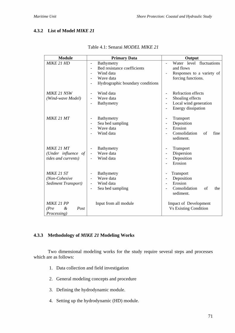
Maritime Unit Shore Protection: Coastal and Hydraulic Study
4.3.2 List of Model MIKE 21
Table 4.1: Senarai MODEL MIKE 21
Module Primary Data Output MIKE 21 HD MIKE 21 NSW (Wind-wave Model) MIKE 21 MT MIKE 21 MT (Under influence of tides and currents) MIKE 21 ST (Non-Cohesive Sediment Transport) MIKE 21 PP (Pre & Post Processing)
- Bathymetry - Bed resistance coefficients - Wind data - Wave data - Hydrographic boundary conditions
- Wind data - Wave data - Bathymetry
- Bathymetry - Sea bed sampling - Wave data - Wind data
- Bathymetry - Wave data - Wind data
- Bathymetry - Wave data - Wind data - Sea bed sampling
Input from all module
- Water level fluctuations and flows
- Responses to a variety of forcing functions.
- Refraction effects - Shoaling effects - Local wind generation - Energy dissipation - Transport - Deposition - Erosion - Consolidation of fine
sediment. - Transport - Dispersion - Deposition - Erosion - Transport - Deposition - Erosion - Consolidation of the
sediment. Impact of Development Vs Existing Condition
4.3.3 Methodology of MIKE 21 Modeling Works
Two dimensional modeling works for the study require several steps and processes
which are as follows:
1. Data collection and field investigation
2. General modeling concepts and procedure
3. Defining the hydrodynamic module.
4. Setting up the hydrodynamic (HD) module.
71
Maritime Unit Shore Protection: Coastal and Hydraulic Study
5. Calibrating and verifying the HD Module.
6. Setting up the sediment transport and dispersion (MT and AD) module
7. Performing simulations for the HD, MT and AD models
8. Analysis of simulation results (Refer Appendix A ) 4.4 ARRANGEMENT OF REPORT
The arrangement of the report should be include as follows:
1. Introduction Introductory material and scope of the Supplementary Hydraulic Report are given.
2. Site Assessment and Data Collection
To describes the findings from site assessment and the result of the data collection.
3. Coastal Engineering Study Work was done in assessing the hydrodynamic influence of the proposal project. This includes the setting-up, simulations and findings of the modeling works.
4.5 SENARAI SEMAKAN BAGI KAJIAN HIDRAULIK 4.5.1 Input Data
Jenis input data bergantung kepada module yang dipertimbangkan dan proses yang akan dinilai . Untuk module hidrodinamik, input data pada amnya terdiri daripada paras pasang-surut, ombak dan bathymetri. Untuk module pergerakan lumpur atau pasir, input ialah ciri-ciri sedimen dan keputusan module hidrodinamik. Untuk module perubahan garis pantai, input ialah ciri-ciri sedimen, ombak dan bathymetri.
Walaubagaimanapun, oleh kerana module hidrodinamik ialah module asas yang perlu dijalankan terlebih dahulu, adalah penting supaya input data untuk module ini disahkan :
a. Data pasang-surut
Diperolehi dengan menjalakan pengukuran sebenar di lokasi yang ditetapkan terlebih dahulu. Pengukuran ini mesti dijalankan untuk tempoh sekurang-
72

Maritime Unit Shore Protection: Coastal and Hydraulic Study
kurangnya dua (2) minggu dan termasuk air pasang dan surut. Data berikut mesti ditunjukkan dengan jelas :
• Lokasi/koordinat stesen pasang-surut • Jenis pengukur pasang-surut yang digunakan • Data pasang-surut
Data pasang surut ini boleh disemak dengan menggunakan jadual pasang surut terbitan Jabatan Hidrografi Tentera Laut Diraja Malaysia atau data yang diterbitkan oleh negara-negara jiran sekiranya stesen pasang-surut adalah terletak dekat pelabuhan di mana ramalan pasang-surut telah dibuat.
Dilaksanakan ??? Ya Tidak
b. Data ombak
Boleh diperolehi daripada pangkalan data SSMO atau pun teknik ‘hindcasting’ atau lain-lain sumber. Sekiranya data adalah dalam bentuk data asal, maka perekabentuk mesti menjalankan:
• Satu analisa statistik terhadap kesemua ombak dalam kawasan terlibat untuk
menentukan ombak dalam ketara (significant wave). • Menjalankan transformasi ombak untuk menentukan ciri-ciri ombak di
kawasan nearshore.
Sekiranya teknik ‘hindcasting’ digunakan, maka perekabentuk mesti :
• Mendapatkan gambarajah Wind Rose Chart (daripada Perkhidmatan Kajicuaca Malaysia)
• Menentukan Critical Fetch Lengths. • Menggunakan teknik ‘hindcasting’ untuk menentukan deepwater significant
wave. • Menjalankan transformasi ombak untuk menentukan ciri-ciri ombak di
kawasan nearshore.
Pada amnya, ‘significant wave height’ di sepanjang pantai barat Semenanjung Malaysia adalah tidak melebihi 2 m, manakala di sepanjang pantai timur Semenanjung Malaysia dan Sabah dan Sarawak adalah tidak melebihi 4m. Walaubagaimanapun, mungkin terdapat kes tertentu di mana ketinggian ombak mungkin berlainan.
Dilaksanakan ??? Ya Tidak
c. Bathymetri Untuk kerja pemodelan biasanya diperolehi daripada Carta Admiralty untuk kawasan laut yang dalam manakala satu kerja ukur hidrografi dijalankan untuk
73

Maritime Unit Shore Protection: Coastal and Hydraulic Study
kawasan nearshore. Bathymetri yang digunakan boleh disahkan daripada Carta Admiralty dan/atau maklumat ukur hidrografi yang lain.
Dilaksanakan ??? Ya Tidak 4.5.2 Penentukuran
Penentukuran model biasanya dijalankan dengan membandingkan paras air dan halaju arus pada spring dan neap tide yang diramalkan dengan nilai yang diukur dan seterusnya membuat pembetulan yang perlu kepada beberapa parameter model supaya dua set data ini akan mencapai persetujuan yang sebaik mungkin. Pengukuran paras air mesti dijalankan untuk sekurang-kurangnya dua (2) minggu dan termasuk neap dan spring tides. Pengukuran halaju mesti dijalankan untuk sekurang-kurangnya 3 hari semasa spring dan neap tides. Data seperti berikut mesti ditunjukkan dengan jelas :
• Lokasi/koordinat stesen penentukuran; • Nilai parameter model yang telah diperbetulkan (misalnya kekasaran, eddy
viscosity dll) • Gambarajah beza paras air (menunjukkan perbandingan paras air untuk nilai
ramalan dan yang terukur) • Gambarajah beza halaju (menunjukkan perbandingan halaju dan arah untuk nilai
ramalan yang terukur)
Dilaksanakan ??? Ya Tidak
4.5.3 Verifikasi
Verifikasi model dijalankan dengan membandingkan paras air dan halaju yang diramalkan pada set masa dan lokasi yang berlainan. Stesen verifikasi mesti cukup jumlahnya dan lokasi mereka mesti berdekatan dengan tempat yang perlu dikaji (kawasan di mana impak mungkin wujud) dalam kajian. Paras air mesti diukurkan untuk sekurang-kurangnya dua (2) minggu manakala pengukuran halaju arus mesti dijalankan untuk sekurang-kurangnya 3 hari semasa spring dan neap tides. Data seperti berikut mesti ditunjukkan dengan jelas :
• Lokasi/koordinat stesen penentukuran; • Nilai parameter model yang telah diperbetulkan (misalnya kekasaran, eddy
viscosity dll) • Gambarajah beza paras air (menunjukkan perbandingan paras air untuk nilai
ramalan dan yang terukur) • Gambarajah beza halaju (menunjukkan perbandingan halaju dan arah untuk nilai
ramalan yang terukur) • Jenis peralatan yang digunakan.
74

Maritime Unit Shore Protection: Coastal and Hydraulic Study
Perbezaan antara halaju dan arah mesti tidak melebihi 30% dan 45 o. Perbezaan antara paras air mesti tidak melebihi 20%. Paten am untuk halaju dan kelajuan seharusnya sama.
Dilaksanakan ??? Ya Tidak 4.5.4 Pelaksanaan Model
Model harus dijalankan untuk kes sebelum projek dan selepas projek. Kes selepas projek boleh merupakan satu larian yang telah mengambil kira kesemua ciri-ciri yang dicadangkan atau pun sekiranya cadangan alternatif dipertimbangkan, model mesti dijalankan untuk setiap alternatif.
Module yang mesti dijalankan boleh terdiri daripada:
• Module Hidrodinamik – menunjukkan paten halaju • Module Pergerakan Lumpur/Pasir – menunjukkan paten hakisan atau pun
pemendapan • Module Perubahan Garis Pantai
Module pertama tidak memerlukan sebarang input berkaitan dengan saiz sedimen.
Maka ia boleh digunakan untuk kawasan berlumpur atau berpasir. Module kedua akan dipilih untuk menampung pantai berlumpur atau pantai berpasir. Module ketiga hanyalah untuk pantai berpasir sahaja.
Dilaksanakan ??? Ya Tidak 4.5.5 Rumusan dan Cadangan
Kajian mesti mengenal pasti kesemua impak yang mungkin berlaku terhadap kawasan bersebelahan akibat projek yang dicadangkan seperti :
• Hakisan atau pemendapan (menunjukkan kawasan yang terlibat untuk jangka pendek dan jangka panjang)
• Masalah saliran. • Pemendapan salur pelayaran.
Ia mesti juga mencadangkan langkah tebatan yang berkesan untuk mengatasi kesemua
impak yang telah dikenalpasti.
Dilaksanakan ??? Ya Tidak
*Catatan : Sumber Ibu pejabat JPS Malaysia.
75

Maritime Unit Shore Protection: Coastal and Hydraulic Study
4.6 REFFERENCES
1. Guidelines For Preparation Of Coastal Engineering Hydraulic Study And Impact Evaluation (JPS); Fifth Edition, December 2001.
2. Guidelines on Erosion Control for Development Projects in The Coastal Zone (JPS),
December 2001.
3. Penilaian KesanKepada Alam Sekeliling (EIA) – Prosedur dan Keperluan Di Malaysia. Cetakan Pertama 21 Oktober 1994.
4. Surat Pekeliling Am Bil.5 Tahun 1987, Jabatan Perdana Menteri.
76

Maritime Unit Shore Protection: Coastal and Hydraulic Study
APPENDIX
77

- Client- Local Residents- Reports & Publications
- Tides - Bathymetry- Waves - Currents- Wind
- Site Visit - Field Data a) Currents b) Water Levels c) Bed Samples d) Water Samples
- MIKE 21- TELEMAC- REFRAC
- For Alternative Site optimal (if required)
- Condition of Chosen Alternatives a) Water Levels, Currents Waves b) Sediment Dispersion c) Seabed Evolution d) Siltation
a) Derive Maximum Currents (Magnitude and Direction)b) Derive Extreme and Significant Wave Height for Various Wave Directions.c) Determine Sedimen Transport and Siltation Ratesd) Determination of Other Related Hydraulic Parameters
Most Viable Alignment to Provide Protection From Wave
RECOMMENDATIONS
DATA COLLECTION
COLLECTION OF SECONDARY DATA
PHASE 1 :
PHASE 3 :
PHASE 2 :MODELLING WORKS
MODELLING WORKS FOR EXISTING &
APPENDIX A: FLOW CHART FOR THE HYDRAULIC STUDY
DATA ANALYSIS & INTERPRETATION
ALTERNATIVE CONDITIONS
TERMS OF REFERENCE(TOR)
SITE ASSESSMENT
FIELD INVESTIGATION
PREDICTION OF IMPACTS
CONCLUSION
RESULTS
SIMULATIONS RUNS

APPENDIX B: DATA COLLECTION
Continuous Monitoring over two(2) weeks.
SEA BED SAMPLING JPS Wave Data Bank
Wind Records from MMS
WAVES / WIND
Grab samples from various locations around 5 km of the project site.
WATER LEVEL & TIDAL FLUCTUATIONS
BATHYMETRY
Admiralty Charts Detail Hydrographic Survey by a
Licensed Surveyor.
CURRENT MEASUREMENT
Deployment of Self-recording Current Meter at the Selected Locations for 3 days
during spring and 3 days during neap.

MOORING ARRANGEMENT OF A CURRENTMETER
APPENDIX C: MOORING ARRANGEMENT OF A CURRENTMETER

APPENDIX D: WIND RECORDER (ANEMOMETER)
ANEMOMETER
The anemometer is used to measure wind direction and speed.
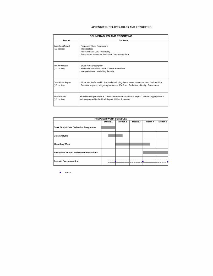
Inception Report - Proposed Study Programme(10 copies) - Methodology
- Assesment of Data Availability- Recommendations for Additional / necessary data
Interim Report - Study Area Description(10 copies) - Preliminary Analysis of the Coastel Processes
- Interpretation of Modelling Results
Draft Final Report - All Works Performed in the Study Including Recommendations for Most Optimal Site,(10 copies) Potential Impacts, Mitigating Measures, EMP and Preliminary Design Parameters
Final Report All Revisions given by the Government on the Draft Final Report Deemed Appropriate to(15 copies) be incorporated in the Final Report.(Within 2 weeks)
Month 3 Month 5
Desk Study / Data Collection Programme
Data Analysis
Modelling Work
Analysis of Output and Recommendations
Report / Documentation
Report
APPENDIX E: DELIVERABLES AND REPORTING
DELIVERABLES AND REPORTINGContentsReport
PROPOSED WORK SCHEDULEMonth 1 Month 2 Month 4