shm systems for bridge inspection and maintenance - case ... · automated shm systems offer ......
TRANSCRIPT
431
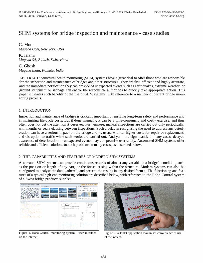
Figure 2. A tablet application maximises convenience of use of the system.
1 INTRODUCTION Inspection and maintenance of bridges is critically important in ensuring long-term safety and performance and in minimising life-cycle costs. But if done manually, it can be a time-consuming and costly exercise, and thus often does not get the attention it deserves. Furthermore, manual inspections are carried out only periodically, with months or years elapsing between inspections. Such a delay in recognising the need to address any deteri-oration can have a serious impact on the bridge and its users, with far higher costs for repair or replacement, and disruption to traffic while such works are carried out. And yet more significantly in many cases, delayed awareness of deterioration or unexpected events may compromise user safety. Automated SHM systems offer reliable and efficient solutions to such problems in many cases, as described below.
2 THE CAPABILITIES AND FEATURES OF MODERN SHM SYSTEMS Automated SHM systems can provide continuous records of almost any variable in a bridge’s condition, such as the position or length of any part, or the forces arising within the structure. Modern systems can also be configured to analyse the data gathered, and present the results in any desired format. The functioning and fea-tures of a typical high-end monitoring solution are described below, with reference to the Robo-Control system of a Swiss bridge products supplier.
IABSE-JSCE Joint Conference on Advances in Bridge Engineering-III, August 21-22, 2015, Dhaka, Bangladesh. ISBN: 978-984-33-9313-5 Amin, Okui, Bhuiyan, Ueda (eds.) www.iabse-bd.org
SHM systems for bridge inspection and maintenance - case studies
G. Moor Mageba USA, New York, USA
K. Islami Mageba SA, Bulach, Switzerland
C. Ghosh Mageba India, Kolkata, India
ABSTRACT: Structural health monitoring (SHM) systems have a great deal to offer those who are responsible for the inspection and maintenance of bridges and other structures. They are fast, efficient and highly accurate, and the immediate notification they can provide of unexpected events such as earthquakes, extreme weather, or ground settlement or slippage can enable the responsible authorities to quickly take appropriate action. This paper illustrates such benefits of the use of SHM systems, with reference to a number of current bridge moni-toring projects.
Figure 1. Robo-Control monitoring system - user interface on the internet.
432
The system offers both a portable version, for short-term applications, and a permanent version, for long-term applications. The portable version, for temporary use, is a stand-alone unit, comprising just a briefcase-held computer and sensors as required. The permanent version, on the other hand, which generally remains installed for at least a year, is typically provided with a local power source and a means of transmitting data to the sys-tem’s central server, where it is automatically processed and made easily accessible from anywhere in the world via the internet.
Figure 1 shows a view of the system’s Dashboard - the user interface which provides authorised users with remote access to system data, requiring only an internet connection and a password. A tablet (e.g. iPad) appli-cation (Figure 2) makes using the system during a bridge visit especially convenient.
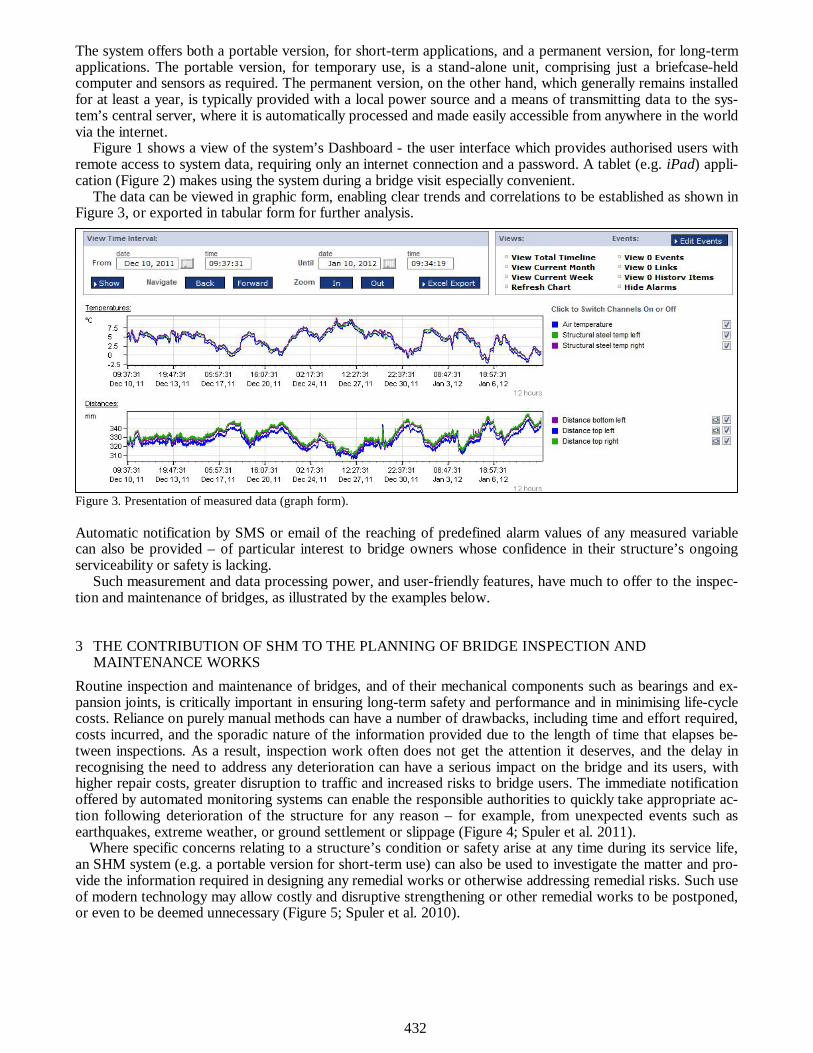
The data can be viewed in graphic form, enabling clear trends and correlations to be established as shown in Figure 3, or exported in tabular form for further analysis.
Figure 3. Presentation of measured data (graph form). Automatic notification by SMS or email of the reaching of predefined alarm values of any measured variable can also be provided – of particular interest to bridge owners whose confidence in their structure’s ongoing serviceability or safety is lacking.
Such measurement and data processing power, and user-friendly features, have much to offer to the inspec-tion and maintenance of bridges, as illustrated by the examples below.
3 THE CONTRIBUTION OF SHM TO THE PLANNING OF BRIDGE INSPECTION AND MAINTENANCE WORKS
Routine inspection and maintenance of bridges, and of their mechanical components such as bearings and ex-pansion joints, is critically important in ensuring long-term safety and performance and in minimising life-cycle costs. Reliance on purely manual methods can have a number of drawbacks, including time and effort required, costs incurred, and the sporadic nature of the information provided due to the length of time that elapses be-tween inspections. As a result, inspection work often does not get the attention it deserves, and the delay in recognising the need to address any deterioration can have a serious impact on the bridge and its users, with higher repair costs, greater disruption to traffic and increased risks to bridge users. The immediate notification offered by automated monitoring systems can enable the responsible authorities to quickly take appropriate ac-tion following deterioration of the structure for any reason – for example, from unexpected events such as earthquakes, extreme weather, or ground settlement or slippage (Figure 4; Spuler et al. 2011).
Where specific concerns relating to a structure’s condition or safety arise at any time during its service life, an SHM system (e.g. a portable version for short-term use) can also be used to investigate the matter and pro-vide the information required in designing any remedial works or otherwise addressing remedial risks. Such use of modern technology may allow costly and disruptive strengthening or other remedial works to be postponed, or even to be deemed unnecessary (Figure 5; Spuler et al. 2010).
433
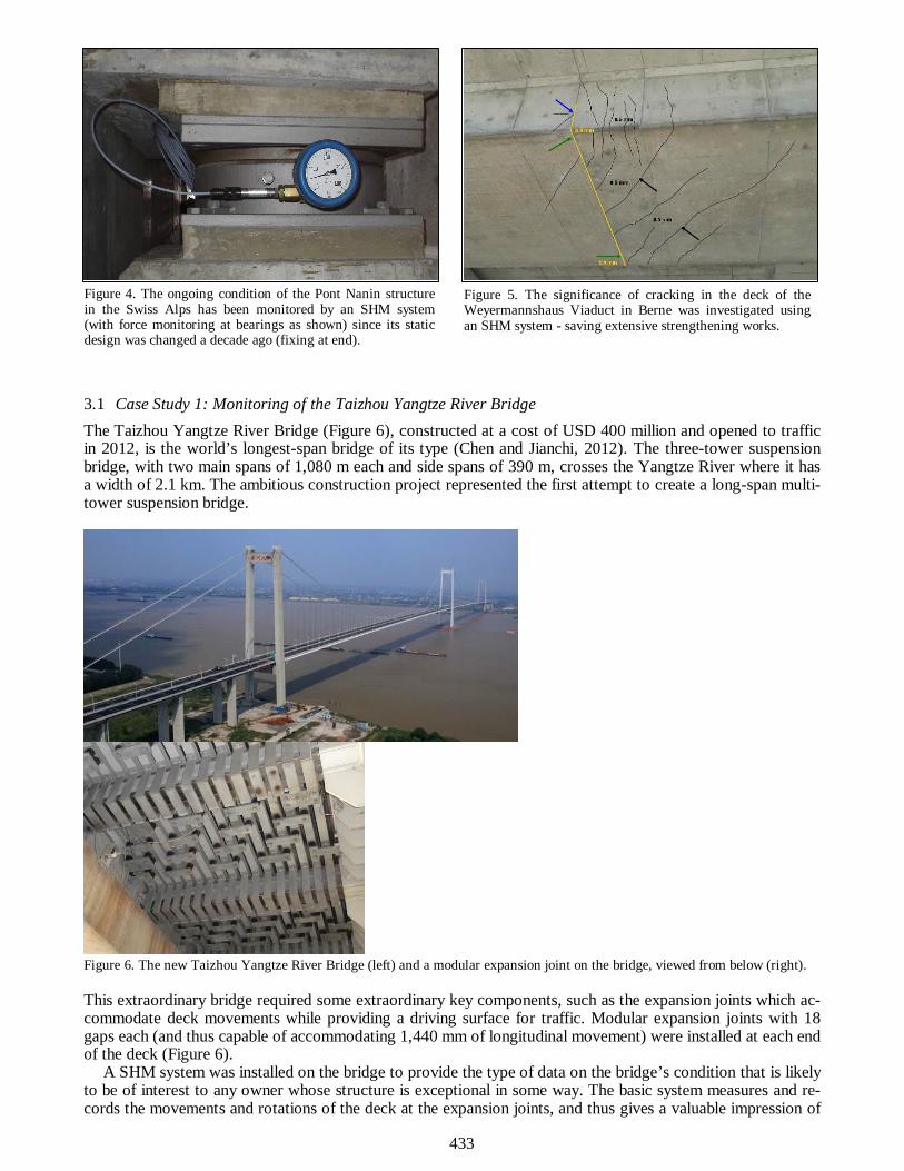
3.1 Case Study 1: Monitoring of the Taizhou Yangtze River Bridge The Taizhou Yangtze River Bridge (Figure 6), constructed at a cost of USD 400 million and opened to traffic in 2012, is the world’s longest-span bridge of its type (Chen and Jianchi, 2012). The three-tower suspension bridge, with two main spans of 1,080 m each and side spans of 390 m, crosses the Yangtze River where it has a width of 2.1 km. The ambitious construction project represented the first attempt to create a long-span multi-tower suspension bridge.
Figure 6. The new Taizhou Yangtze River Bridge (left) and a modular expansion joint on the bridge, viewed from below (right). This extraordinary bridge required some extraordinary key components, such as the expansion joints which ac-commodate deck movements while providing a driving surface for traffic. Modular expansion joints with 18 gaps each (and thus capable of accommodating 1,440 mm of longitudinal movement) were installed at each end of the deck (Figure 6).
A SHM system was installed on the bridge to provide the type of data on the bridge’s condition that is likely to be of interest to any owner whose structure is exceptional in some way. The basic system measures and re-cords the movements and rotations of the deck at the expansion joints, and thus gives a valuable impression of
Figure 4. The ongoing condition of the Pont Nanin structure in the Swiss Alps has been monitored by an SHM system (with force monitoring at bearings as shown) since its static design was changed a decade ago (fixing at end).
Figure 5. The significance of cracking in the deck of the Weyermannshaus Viaduct in Berne was investigated using an SHM system - saving extensive strengthening works.
434
the performance of the structure at any time, enabling the need for maintenance or adaptation work to be quickly identified and planned. It also reports accumulated sliding movements over time – a key indicator in evaluating and predicting the condition of key mechanical components such as expansion joints and bearings.
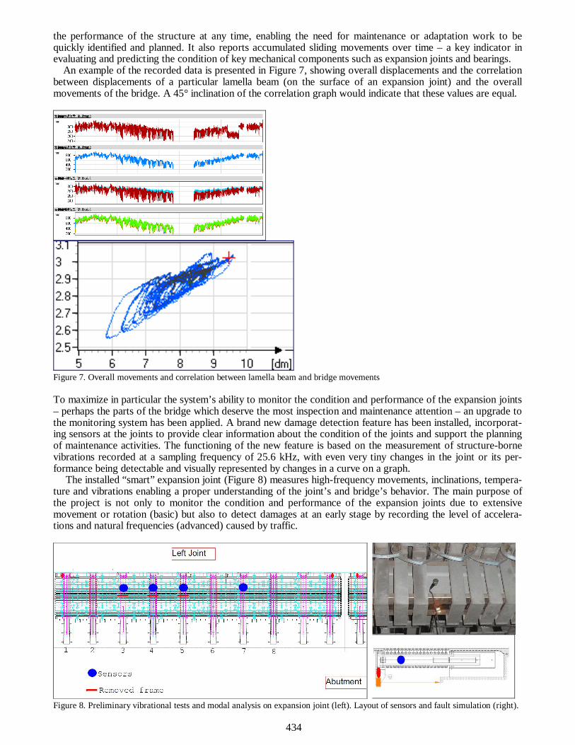
An example of the recorded data is presented in Figure 7, showing overall displacements and the correlation between displacements of a particular lamella beam (on the surface of an expansion joint) and the overall movements of the bridge. A 45° inclination of the correlation graph would indicate that these values are equal.
Figure 7. Overall movements and correlation between lamella beam and bridge movements To maximize in particular the system’s ability to monitor the condition and performance of the expansion joints – perhaps the parts of the bridge which deserve the most inspection and maintenance attention – an upgrade to the monitoring system has been applied. A brand new damage detection feature has been installed, incorporat-ing sensors at the joints to provide clear information about the condition of the joints and support the planning of maintenance activities. The functioning of the new feature is based on the measurement of structure-borne vibrations recorded at a sampling frequency of 25.6 kHz, with even very tiny changes in the joint or its per-formance being detectable and visually represented by changes in a curve on a graph.
The installed “smart” expansion joint (Figure 8) measures high-frequency movements, inclinations, tempera-ture and vibrations enabling a proper understanding of the joint’s and bridge’s behavior. The main purpose of the project is not only to monitor the condition and performance of the expansion joints due to extensive movement or rotation (basic) but also to detect damages at an early stage by recording the level of accelera-tions and natural frequencies (advanced) caused by traffic.
Figure 8. Preliminary vibrational tests and modal analysis on expansion joint (left). Layout of sensors and fault simulation (right).
435
0
10
20M
ax V
ib. [
m/s
2]
Vib. at Joist 3 - Left Joint
0
10
20
Max
Vib
. [m
/s2]
Vib. at Joist 4 - Left Joint
0
10
20
Max
Vib
. [m
/s2]
Vib. at Joist 5 - Left Joint
28/09/14 05/10/14 12/10/14 19/10/14 26/10/14 02/11/140
10
20
Date
Max
Vib
. [m
/s2]
Vib. at Joist 7 - Left Joint
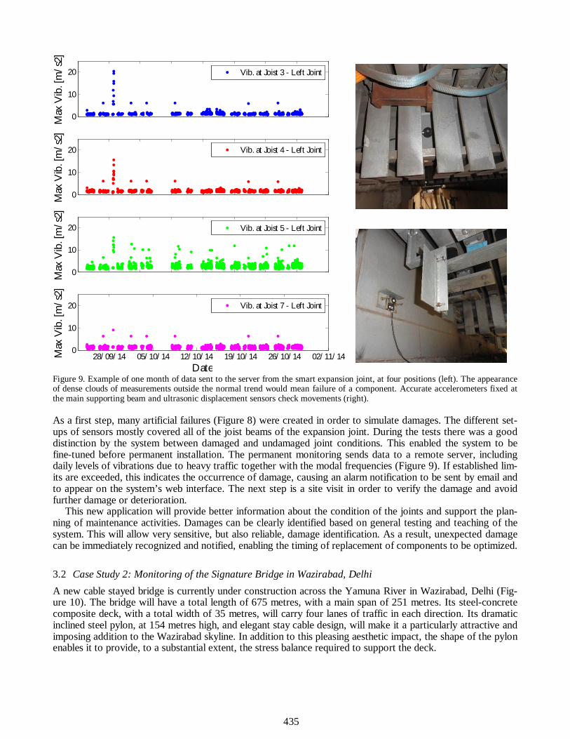
Figure 9. Example of one month of data sent to the server from the smart expansion joint, at four positions (left). The appearance of dense clouds of measurements outside the normal trend would mean failure of a component. Accurate accelerometers fixed at the main supporting beam and ultrasonic displacement sensors check movements (right). As a first step, many artificial failures (Figure 8) were created in order to simulate damages. The different set-ups of sensors mostly covered all of the joist beams of the expansion joint. During the tests there was a good distinction by the system between damaged and undamaged joint conditions. This enabled the system to be fine-tuned before permanent installation. The permanent monitoring sends data to a remote server, including daily levels of vibrations due to heavy traffic together with the modal frequencies (Figure 9). If established lim-its are exceeded, this indicates the occurrence of damage, causing an alarm notification to be sent by email and to appear on the system’s web interface. The next step is a site visit in order to verify the damage and avoid further damage or deterioration.
This new application will provide better information about the condition of the joints and support the plan-ning of maintenance activities. Damages can be clearly identified based on general testing and teaching of the system. This will allow very sensitive, but also reliable, damage identification. As a result, unexpected damage can be immediately recognized and notified, enabling the timing of replacement of components to be optimized.
3.2 Case Study 2: Monitoring of the Signature Bridge in Wazirabad, Delhi A new cable stayed bridge is currently under construction across the Yamuna River in Wazirabad, Delhi (Fig-ure 10). The bridge will have a total length of 675 metres, with a main span of 251 metres. Its steel-concrete composite deck, with a total width of 35 metres, will carry four lanes of traffic in each direction. Its dramatic inclined steel pylon, at 154 metres high, and elegant stay cable design, will make it a particularly attractive and imposing addition to the Wazirabad skyline. In addition to this pleasing aesthetic impact, the shape of the pylon enables it to provide, to a substantial extent, the stress balance required to support the deck.

436
Figure 10. Wazirabad’s new Signature Bridge – currently under construction in Delhi. The bridge is being equipped with a sophisticated structural health monitoring system (Furtner et al, 2013) to monitor the structure’s behaviour, performance and condition, with three main focuses:
i. structural health monitoring and damage detection; ii. monitoring of weather loading (e.g. temperature, storms); and iii. earthquake monitoring.
It will consist of the following: i. a total of 104 sensors, using data 171 channels, to measure environmental, load and structural re-
sponse factors (see Figure 11); ii. a signal acquisition solution, including signal capture from the sensors, signal verification and tempera-
ture adjustment, conversion of signal to digital format using 24 bit architecture, 1/1000 sec. signal time synchronisation, signal transport to pre-processing data acquisition unit, signal pre-processing and buffering prior to transferring to data processing;
iii. data processing to generate reports, prompt control actions and provide alarms as required; iv. data storage; and v. a user-friendly interface to enable necessary operational intervention, maintenance optimisation and
support high level analysis such as finite element.
Figure 11. Summary of sensors The automated monitoring system which is being provided for the new Signature Bridge in Wazirabad will provide enormous amounts of information which will enable the conditions to which the bridge is subjected, and the structure’s condition and performance, to be precisely evaluated with a minimum of effort. It is thus a good example of the type of comprehensive service which can be provided by modern SHM systems, if sensi-bly conceived, detailed and implemented.
437
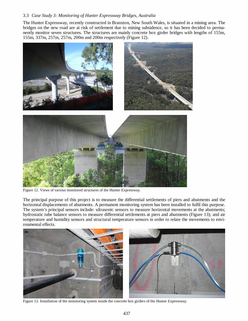
3.3 Case Study 3: Monitoring of Hunter Expressway Bridges, Australia The Hunter Expressway, recently constructed in Branxton, New South Wales, is situated in a mining area. The bridges on the new road are at risk of settlement due to mining subsidence, so it has been decided to perma-nently monitor seven structures. The structures are mainly concrete box girder bridges with lengths of 155m, 155m, 337m, 257m, 257m, 200m and 200m respectively (Figure 12).
Figure 12. Views of various monitored structures of the Hunter Expressway. The principal purpose of this project is to measure the differential settlements of piers and abutments and the horizontal displacements of abutments. A permanent monitoring system has been installed to fulfil this purpose. The system’s principal sensors include: ultrasonic sensors to measure horizontal movements at the abutments; hydrostatic tube balance sensors to measure differential settlements at piers and abutments (Figure 13); and air temperature and humidity sensors and structural temperature sensors in order to relate the movements to envi-ronmental effects.
Figure 13. Installation of the monitoring system inside the concrete box girders of the Hunter Expressway.

438
All measurements are accurately gathered in a double database and immediately visible in the project’s SHM web interface. Figure 14 shows one of the online system “cockpits” that the end-user can access day or night. The measurements on two bridges are shown: west and east structures. The following data is measured and re-corded at the abutments and piers:
i. At the abutments: displacement in longitudinal and transverse direction of the expansion joint, settle-ments and temperature
ii. At the piers: settlements relative to the right or left abutment and temperature iii. Additionally, the level of the reservoir is measured to ensure an appropriate accuracy.
Figure 14. Web interface “cockpit” of the Hunter Expressway SHM system. Not only can the responsible engineers check settlements at any time, they can also view the entire time history of the measurements graphically (Figure 15). Any abnormal settlements will be immediately recognisable, ena-bling safety precautions to be implemented. To ensure that the information is immediately recognised by the engineers, even when not in the office, the system also includes an alarm feature which will provide immediate notification of such an occurrence by email or SMS.
Figure 15. Data records for one-month settlement measurements at one bridge.

439
Figure 16. Data records for half-year settlement measurements at another bridge. It is interesting to observe the displacements and settlements in Figure 16, where six months of measurements are presented. These show that longitudinal displacements at the bridge’s expansion joints are highly dependent on temperature, while settlements at every pier and abutment are not influenced by environmental parameters, as might be expected. Happily, since the installation took place, the SHM system has been able to confirm that no significant settlement has occurred.
4 CONCLUSIONS Automated monitoring systems offer many benefits over traditional manual observation and measurement methods: they are typically much more efficient, having far lower “running costs”; they are capable of an ex-traordinary level of detail and accuracy, e.g. in measuring high-frequency vibrations that would scarcely be reg-istered by human touch; and they can be set up to operate 24 hours a day, 7 days a week, for as long as re-quired, and can thus be relied on to immediately record and report unexpected / serious events, no matter when they might occur. Thanks to these benefits, such systems can be used to serve many purposes in relation to bridges and other structures, and effectiveness and efficiency dictate that the use of automated monitoring sys-tems to support inspection and maintenance activities should be considered for all important bridges.
REFERENCES Chen, C. & Jianchi, Z. 2012. Taizhou Triple. Bd&e Magazine Issue 66. London, UK. Furtner, P., Della Ca’, D. & Ghosh, C. 2013. Structural health monitoring of Signature Bridge in Delhi - the BSHMS for the Wa-
zirabad Bridge Project. Proc. IABSE Symposium on Long Span Bridges and Roofs, Kolkata, India. Spuler, T. Moor, G., O’Suilleabhain, C. & Berger, R. 2011. Modern remote structural health monitoring - providing long-term
confidence in a structure’s condition. Proc. Middle East Conf. on Smart Monitoring, Assessment and Rehab. of Civil Struc-tures, Dubai, UAE.
Spuler, T. Moor, G. & Berger, R. 2010. Automated structural health monitoring – filling a knowledge gap. Proc. 3rd fib Interna-tional Congress, Washington D.C., USA.