sherco ignition timing guide
TRANSCRIPT

Sherco Ignition Timing, Rev.0902 1
Sherco Ignition Timing Guide
This guide is designed to provide the Sherco owner with instructions on how to check and adjust the ignition timing on the 1999 – 2003 series Sherco 1.25, 2.0, 2.5 and 2.9 models.
The bike photographed in this manual is a new 2003 2.9, but the same principles apply for the 1.25 through 2.5 models, too. The same brand and type of magneto/ignition is used from “99 – 03”. There may be some minor appearance changes.
You will require a flywheel puller, which is available from Ryan Young Products.
You may want to obtain a Sherco timing pin and a dial indicator.The Sherco timing pin is available from Ryan Young Products, the dial indicator will have to be obtained from a tool supply house. For a location see page 16.
If you have any questions about the procedure, please call Ryan Young Products at 1-800-607-8742.

Sherco Ignition Timing, Rev.0902 2
Ignition Timing Comments
For general purpose use, we recommend maintaining the factory ignition timing setting and adjusting one’s riding style to the performance of the bike. In the event that the factory setting does not meet your performance requirements due to altitude or riding style, this manual will define the steps required to modify the factory timing.
Note that the timing setting of the particular bike photographed in this manual was slightly more advanced than the specification. The owner of the bike is very satisfied with the performance and it is not pinging, for this bike it was unnecessary to change the timing to the precise factory setting. The factory timing setting is a compromise between achieving maximum RPM and smooth low end response plus ease of starting. The stator plate tends to be factory positioned in such a way that it is biased more in the advanced direction. Therefore, while there is some adjustment room to advance the timing, there is much more room to retard it.
Why Advance the Timing Beyond the Factory Setting?
Generally speaking, there may be little overall advantage. The result will create quicker bottom end engine response and an increase in idle speed, but the motor may also kick back more when starting, or show some tendency to ping when hot under quick applications of throttle. Advancing beyond factory settings is beneficial for riding at high altitudes, as it will return some of the engine response lost from thin air. To experiment, adjust the timing to the full advanced position, as far as the slots allow.

Sherco Ignition Timing, Rev.0902 3
Ignition Timing Comments, continued
Why Retard the Timing Beyond the Factory Setting?
Retarding creates a softer low-end engine response for riders who rarely ride at maximum RPM. Other benefits include: easier starting and much smoother slow riding in first gear with no clutch, and preventing wheel spin in slippery terrain. Retarding will necessitate an increase in idle speed which can be achieved by turning in the carb idle screw.
To experiment with retarding, first fully retard the ignition as far as the slots will allow. Note that adjusting the timing in small, precise increments will not provide an appreciable performance difference. Increase the carburetor idle speed appropriately, then test ride the bike. Next, try a setting half way between factory and fully retarded. By testing the bike’s performance at extreme timing settings, it becomes easier to chose a setting suitable for riding style or conditions.
Idle Considerations
The idle, regardless of timing setting, should be adjusted to prevent engine stalling. The idle speed is correctly adjusted when the bike can creep forward (with no throttle) in first gear by merely dragging the clutch. Perform this test on flat, smooth ground.
Note: Use caution when moving the stator plate as damage to the wiring harness can occur.

Sherco Ignition Timing, Rev.0902 4
Factory Ignition Timing Specifications
3.0mm3.0mm3.0mm3.0mm20033.8mm3.8mm3.1mm3.0mm20022.7mm2.5mm3.1mm3.0mm20012.7mm2.5mm3.1mm3.0mm2000--------2.5mm----------------1999
2.92.52.01.25
These specifications are Before Top Dead Center (BTDC)

Sherco Ignition Timing, Rev.0902 5
Remove gear shift lever bolt Remove ignition cover
Remove the gear shift lever bolt by using a 5mm Allen wrench. Insert the wrench through the hole in the skid plate. Holding the gear shifter up in second gear makes it easier to align the wrench into the head of the bolt.
Pull the gear shift lever as far as possible towards the chain. (The chain does not have to be removed in order to remove the ignition cover and flywheel)
5 mm Allen wrench
Remove the three ignition cover bolts by using a 4mm Allen wrench.
Carefully remove the ignition cover-which requires a little twisting and some outward pressure on the gear shift lever. The shift lever may also have to be pressed down into the first gear position.

Sherco Ignition Timing, Rev.0902 6
Glue gasket to cover Remove flywheel
Chisel marks
Factory paint mark
Inspect the rubber ring gasket for cracks or cuts while the ignition cover is off. Replace if necessary. We recommended applying a ring of high grade silicone sealant to further improve the seal of the rubber ring gasket.
Tap a chisel-mark across the flywheel retaining nut and the crankshaft by using a small, sharp chisel. This mark serves as a reference point for retightening the flywheel in its original position during reassembly.

Sherco Ignition Timing, Rev.0902 7
Remove the flywheel retaining nut using a small impact tool fitted with a 19mm (3/4”) socket. Note that there is no washer under the nut.
Remove flywheel, cont.
View showing the flywheel retaining nut removed.
Back off the push bolt and thread the Sherco flywheel puller into the flywheel, until the threads bottom. The puller does not have to be tightened with a wrench.

Sherco Ignition Timing, Rev.0902 8
Remove flywheel, cont.
3 Bolts3 Slots
Hold the flywheel removal tool with either an adjustable wrench as shown, or a 24mm (15/16”) open end wrench. Tighten the removal tool screw by using a small impact tool fitted with a 16mm (5/8”) socket until the flywheel comes loose from the crankshaft.
Carefully remove the flywheel - it requires a little twisting and some outward pressure on the gear shift lever. Be careful not to misplace the alignment key.
View showing the flywheel removed with the stator assembly exposed. Notice that it is retained with three bolts, and that the backing plate is slotted.
Note: Spraying the inside of the case, the stator plate, and the flywheel with clear lacquer will help prevent corrosion.

Sherco Ignition Timing, Rev.0902 9
Mark factory timing setting
Chisel markTap a straight,
sharp chisel mark across the stator plate and its fixing bracket to identify the factory position of the stator.
With this mark, the timing can always be returned to the factory setting, no matter how many timing changes are made.

Sherco Ignition Timing, Rev.0902 10
Check the timing using a dial indictor and timing pin
TDC chisel mark
Factory mark on flywheel
Remove the spark plug by using a 13/16” spark plug wrench.
Install the dial indicator into the cylinder head.
Follow the instructions included with the dial indicator to set it at “0” for top dead center.
Reinstall the flywheel on the crankshaft, but do not yet install the flywheel retaining nut.
For future reference, use a small, sharp chisel and mark the Top Dead Center location on the engine case, as shown above.

Sherco Ignition Timing, Rev.0902 11
Check timing, cont.
Hand-rotate the flywheel clockwise, watching the dial indicator needle. When it is close to the factory specified timing, insert the timing pin. The pin should fit into the timing hole in the stator plate. Do not insert the pin too far, which will make it difficult to remove.
Read the dial indicator with the pin inserted. This reading represents the factory timing.
Note: Engine rotation is Counterclockwise.

Sherco Ignition Timing, Rev.0902 12
Change timing
Remove the timing pin and the flywheel.
To advance the timing, loosen the three bolts of the stator plate (4mm Allen wrench), and rotate the backing plate Clockwise.
To retard the timing, loosen the three bolts of the stator plate, and rotate the backing plate Counterclockwise.
Once the backing plate has been moved into the desired position, reinstall the flywheel. Check the reading on the dial indicator, repeat the process until the correct desired dial indication is achieved.
The factory timing on this engine reads 3.51mm BTDC. The factory specification is 3.0mm BTDC, which means that this particular engine’s timing is advanced. The dial actually reads 3.49 but since the indicator is moving away from zero you have to read it as 3.51.
Check timing, cont.
Note: Use caution when moving the stator plate as damage to the wiring harness can occur.
Sherco Ignition Timing, Rev.0902 13
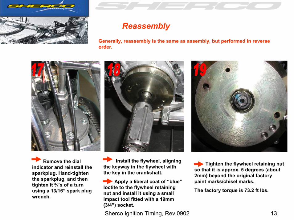
ReassemblyGenerally, reassembly is the same as assembly, but performed in reverse order.
Remove the dial indicator and reinstall the sparkplug. Hand-tighten the sparkplug, and then tighten it ¾’s of a turn using a 13/16” spark plug wrench.
Install the flywheel, aligning the keyway in the flywheel with the key in the crankshaft.
Apply a liberal coat of “blue” loctite to the flywheel retaining nut and install it using a small impact tool fitted with a 19mm (3/4”) socket.
Tighten the flywheel retaining nut so that it is approx. 5 degrees (about 2mm) beyond the original factory paint marks/chisel marks.
The factory torque is 73.2 ft lbs.

Sherco Ignition Timing, Rev.0902 14
Reassembly, cont.
Reinstall the ignition cover. Apply anti-seize to the three retaining bolts. Do not over- tighten these three bolts. Use a 4mm Allen wrench.
Reinstall the gear shift lever bolt by using a 5mm Allen wrench.
Reinstall the fuel tank, reconnecting both the fuel line and the overflow line.
Reinstall the rear fender.
Test ride the bike to confirm that the settings are suitable.
Sherco Ignition Timing, Rev.0902 15
Changing ignition timing without using a dial indicator
1. Follow Steps 1 through 10.
2. Refer to Step 16 (page 12): To advance the timing, loosen the three bolts (4mm Allen wrench) and rotate the backing plate Clockwise.
3. To retard the timing, loosen the three bolts and rotate the backing plate Counterclockwise.
4. Make the desired adjustments, then reinstall the flywheel and the flywheel retaining nut. It is not necessary to torque the nut at this time because you may want to remove it. The nut should be tightened enough to ensure that the flywheel does not come off during the test ride.
5. Test-ride the bike to determine if the performance results are satisfactory, and if so, follow steps 18 – 21 to complete this project. If the performance is not satisfactory, repeat steps 2 – 4 above.
Note: Use caution when moving the stator plate as damage to the wiring harness can occur.

Sherco Ignition Timing, Rev.0902 16
Motorcycle Timing Gage
ToolSource #: 91545
Manufacturer #: 6491
Manufacturer: Central Tools, Inc
This item is available from “ToolSource” 1-888-220-8350 http://toolsource.com:888/ost/Default.asp